60.10 depend-o-lok exe non-restrained flexible … exe non-restrained flexible coupling a coupling...
TRANSCRIPT

Depend-O-Lok ExE non-restrained couplings are bolted, split-sleeve couplings that meet or
exceed the design, materials and performance requirements set forth in AWWA. They are
specifically designed to allow for:
Angular deflection at the pipe joint
Vibration reduction
Maintaining the full integrity of the coupling seal.
The design features and benefits of this coupling, and the entire Depend-O-Lok product
line give the piping industry freedom of design and applications not found with other
couplings. D-O-L offers savings in both cost of components and man-hours for installation.
Because of its versatility, pipe detailing, pipe fabrication and field time are reduced to a
minimum. The coupling and gasket assembly is easy to handle, minimizing installed costs.
The D-O-L ExE Type 1 & Type 2 couplings are designed to seal the pipe joint and to
provide for flexibility at the pipe joint. It is important to note that ExE couplings are a non-
restrained joint. Please refer to the latest edition of AWWA Manual M11 “Steel Water Pipe:
A Guide for Design and Installation” for harness lug requirements.
Depend-O-Lok accommodates many irregularities commonly found in all types of large
diameter pipe, making it more “forgiving” than other joining methods.
For quotations, ordering, or technical information, call 770-840-0662 or FAX
770-840-8312.
•
•
•
NON-RESTRAINED COUPLING
COMPONENTS AND BENEFITS
1 Closure Plates simplify installation and enable the coupling to seal with fewer bolts than traditional
sleeve type couplings. They also allow the coupling to be provided in multiple segments for ease of
handling or installation on existing pipe.
2 Split-sleeve (body) is designed for the internal pressure requirements of the project. The “double
arch” shape of the sleeve provides high section modulus and strengthens the pipe joint. The low
profile design permits the coupling to pass through tighter openings than traditional sleeve type and
for assembly in close quarters. Harness lugs, if required, can be shorter.
3 O-rings. Proven effective during more than 80 years of use.
4 Sealing Plate/Pad ensures leak-tight seal on joints, and accommodates a wide range of variances
in mated pipe OD.
5 Bolts and Nuts are sized to provide yield strength greater than the hoop strength of the coupling
body, and utilize flat washers. Stainless steel or hot dipped galvanized bolting are available.
1
2
4
3
5
5
60.10_1
Depend-O-Lok ExE Non-Restrained Flexible CouplingA COUPLING SYSTEM THAT PROVIDES NON-RESTRAINED PIPE JOINTS.
SIMPLE, RUGGED AND DEPENDABLE
60.10DEPEND-O-LOK ExE NON-RESTRAINED FLEXIBLE COUPLING
JOB/OWNER CONTRACTOR ENGINEER
System No. __________________________ Submitted By ________________________ Spec Sect ____________ Para __________
Location ____________________________ Date ________________________________ Approved ___________________________
Date ________________________________
www.victaulic.com
VICTAULIC IS A REGISTERED TRADEMARK OF VICTAULIC COMPANY. © 2006 VICTAULIC COMPANY. ALL RIGHTS RESERVED. PRINTED IN THE USA.
REV_C
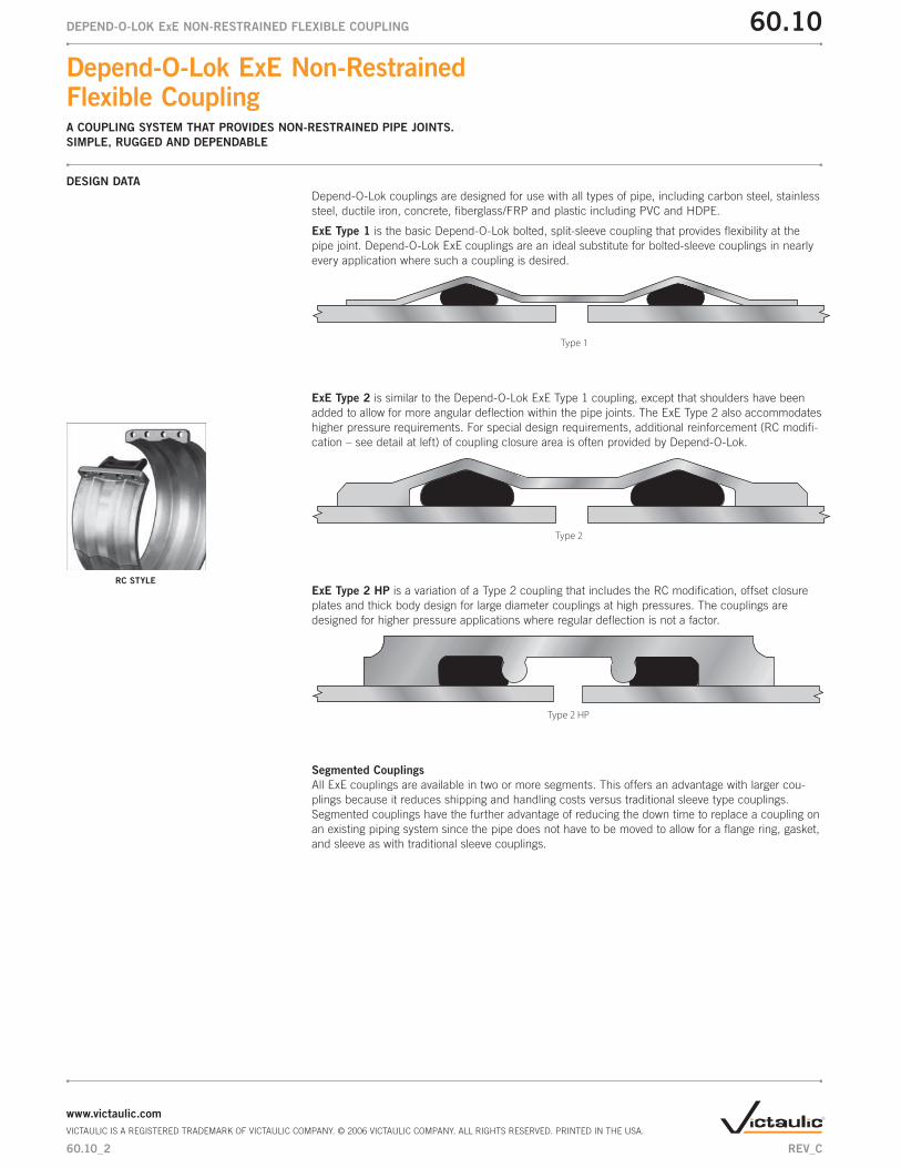
Depend-O-Lok couplings are designed for use with all types of pipe, including carbon steel, stainless
steel, ductile iron, concrete, fiberglass/FRP and plastic including PVC and HDPE.
ExE Type 1 is the basic Depend-O-Lok bolted, split-sleeve coupling that provides flexibility at the
pipe joint. Depend-O-Lok ExE couplings are an ideal substitute for bolted-sleeve couplings in nearly
every application where such a coupling is desired.
Type 1
ExE Type 2 is similar to the Depend-O-Lok ExE Type 1 coupling, except that shoulders have been
added to allow for more angular deflection within the pipe joints. The ExE Type 2 also accommodates
higher pressure requirements. For special design requirements, additional reinforcement (RC modifi-
cation – see detail at left) of coupling closure area is often provided by Depend-O-Lok.
Type 2
ExE Type 2 HP is a variation of a Type 2 coupling that includes the RC modification, offset closure
plates and thick body design for large diameter couplings at high pressures. The couplings are
designed for higher pressure applications where regular deflection is not a factor.
Type 2 HP
Segmented Couplings
All ExE couplings are available in two or more segments. This offers an advantage with larger cou-
plings because it reduces shipping and handling costs versus traditional sleeve type couplings.
Segmented couplings have the further advantage of reducing the down time to replace a coupling on
an existing piping system since the pipe does not have to be moved to allow for a flange ring, gasket,
and sleeve as with traditional sleeve couplings.
DESIGN DATA
RC STYLE
60.10_2
Depend-O-Lok ExE Non-Restrained Flexible CouplingA COUPLING SYSTEM THAT PROVIDES NON-RESTRAINED PIPE JOINTS.
SIMPLE, RUGGED AND DEPENDABLE
60.10DEPEND-O-LOK ExE NON-RESTRAINED FLEXIBLE COUPLING
www.victaulic.com
VICTAULIC IS A REGISTERED TRADEMARK OF VICTAULIC COMPANY. © 2006 VICTAULIC COMPANY. ALL RIGHTS RESERVED. PRINTED IN THE USA.
REV_C
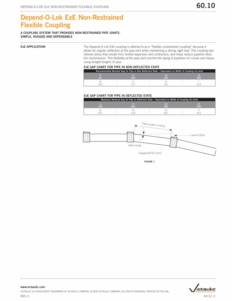
The Depend-O-Lok ExE coupling is referred to as a “flexible unrestrained coupling” because it
allows for angular deflection at the pipe joint while maintaining a strong, tight seal. The coupling also
relieves stress that results from limited expansion and contraction, and helps reduce pipeline vibra-
tion transmission. This flexibility at the pipe joint permits the laying of pipelines on curves and slopes
using straight lengths of pipe.
ExE GAP CHART FOR PIPE IN NON-DEFLECTED STATE
Recommended Nominal Gap for Pipe in Non-Deflected State – Dependent on Width of Coupling (In./mm)
5 25
8200
10250
12300
3⁄8 ½ ¾ 119.5 12.7 19.1 25.4
ExE GAP CHART FOR PIPE IN DEFLECTED STATE
Maximum Nominal Gap for Pipe in Deflected State – Dependent on Width of Coupling (In./mm)
5125
8200
10250
12300
¾ 1¼ 1½ 319.1 31.8 38.1 76.2
Lateral Offset
Pipe Length in Inches
Offset Angle
Exaggerated for Clarity
FIGURE 1
ExE APPLICATION
60.10_3
Depend-O-Lok ExE Non-Restrained Flexible CouplingA COUPLING SYSTEM THAT PROVIDES NON-RESTRAINED PIPE JOINTS.
SIMPLE, RUGGED AND DEPENDABLE
60.10DEPEND-O-LOK ExE NON-RESTRAINED FLEXIBLE COUPLING
www.victaulic.com
VICTAULIC IS A REGISTERED TRADEMARK OF VICTAULIC COMPANY. © 2006 VICTAULIC COMPANY. ALL RIGHTS RESERVED. PRINTED IN THE USA.
REV_C

LATERAL OFFSET
To determine the lateral offset in inches, multiply the sine value of the offset angle by the pipe length
in inches.
Example: A 2° offset angle with a pipe length of 40 feet (480 inches).
Calculation:
Sine of 2° = .035
.035 x 480" = 16.8"
The approximate lateral offset would be 16.8".
Sine Values:
1° = .017
2° = .035
3° = .052
4° = .070
“RULE OF THUMB” EXAMPLE
The general “Rule of Thumb” for lateral offset is 2.1" per 1° offset angle per 10' of pipe length.
Assume:
1. Pipe length is 40'
2. Offset angle is 3°
Calculation:
2.1" x 3 x 4 = 25.2"
The approximate lateral offset would be 25.2".
60.10_4
Depend-O-Lok ExE Non-Restrained Flexible CouplingA COUPLING SYSTEM THAT PROVIDES NON-RESTRAINED PIPE JOINTS.
SIMPLE, RUGGED AND DEPENDABLE
60.10DEPEND-O-LOK ExE NON-RESTRAINED FLEXIBLE COUPLING
www.victaulic.com
VICTAULIC IS A REGISTERED TRADEMARK OF VICTAULIC COMPANY. © 2006 VICTAULIC COMPANY. ALL RIGHTS RESERVED. PRINTED IN THE USA.
REV_C

DEFLECTION PER JOINT
Chart tabulations are in degrees. If more angular deflection is desired please contact your Victaulic
sales representative for details.
PIPE END GAP
Where couplings are desired to bridge a large gap between two pipe ends the D-O-L ExE is a good
choice. For example, an 18" wide ExE can bridge a gap of up to 8". Please contact Victaulic sales
staff for information.
EXPANSION/CONTRACTION
D-O-L ExE couplings can accommodate limited axial pipe movement. For couplings that require
expansion and contraction capabilities, see section 60.12, FxE Expansion Couplings.
PIPE MOVEMENT
Where pipe movement out of the coupling may occur, proper anchorage of the pipe is essential.
Please refer to sections 60.11, FxF Restrained Coupling, and 60.12, FxE Expansion Couplings, for
additional information.
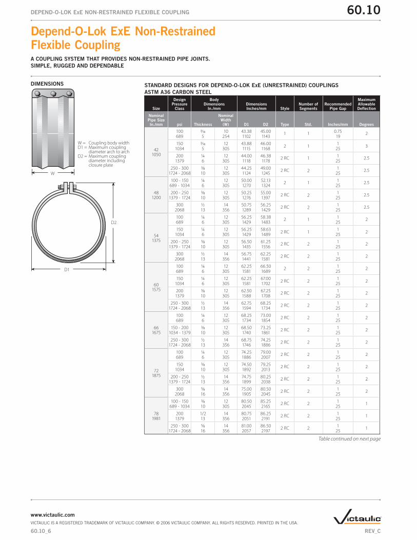
STANDARD DESIGNS FOR DEPEND-O-LOK ExE (UNRESTRAINED) COUPLINGS
ASTM A36 CARBON STEEL
Size
Design Pressure
Class
BodyDimensions
In./mmDimensionsInches/mm Style
Number of Segments
Recommended Pipe Gap
Maximum Allowable Deflection
NominalPipe SizeIn./mm psi Thickness
Nominal Width(W) D1 D2 Type Std. Inches/mm Degrees
6 100 - 300 12 ga. 8 7.25 8.25 1 1 0.50 4.5150 689 - 2068 3 203 184 210 13
8 100 - 300 11 ga. 10 9.25 10.38 1 1 0.75 4200 689 - 2068 3 254 235 264 19
10 100 - 300 10 ga. 10 11.25 12.50 1 1 0.75 4250 689 - 2068 3 254 286 318 19
12 100 - 300 10 ga. 10 13.25 14.50 1 1 0.75 4300 689 - 2068 3 254 337 368 19
14 100 - 300 10 ga. 10 15.25 16.50 1 1 0.75 4350 689 - 2068 3 254 387 419 19
16 100 - 300 10 ga. 10 17.25 18.88 1 1 0.75 3.5400 689 - 2068 3 254 438 480 19
18450
100 - 150 10 ga. 10 19.25 20.88 1 1 0.75 3.5689 - 1034 3 254 489 530 19
200 - 300 3⁄16 10 19.38 21.00 1 1 0.75 3.51379 - 2068 5 254 492 534 19
20500
100 - 150 10 ga. 10 21.25 22.88 1 1 0.75 3.5689 - 1034 3 254 540 581 19
200 - 300 3⁄16 10 21.38 23.00 1 1 0.75 3.51379 - 2068 5 254 543 584 19
24600
100 - 150 10 ga. 10 25.25 26.88 1 1 0.75 3.5689 - 1034 3 254 641 683 19
200 - 250 3⁄16 10 25.38 27.00 1 1 0.75 3.51379 - 1724 5 254 645 686 19
300 ¼ 12 26.00 28.38 2 RC 1 1 42068 6 305 660 721 25
30750
100 - 150 3⁄16 10 31.38 33.00 1 1 0.75 2.5689 - 1034 5 254 797 838 19
200 3⁄16 12 31.88 33.502 1
13
1379 5 305 810 851 25
250 - 300 ¼ 12 32.00 34.38 2 RC 1 1 31724 - 2068 6 305 813 873 25
36900
100 - 150 3⁄16 10 37.38 39.00 1 1 0.75 2.5689 - 1034 5 254 949 991 19
200 ¼ 12 38.00 40.132 1
13
1379 6 305 965 1019 25
250 ¼ 12 38.00 40.38 2 RC 1 1 31724 6 305 965 1026 25
300 3⁄8 12 38.50 43.00 2 RC 2 1 32068 10 305 978 1092 25
Shaded areas are gauge/mm. All unshaded areas are in/mm.
DIMENSIONS
W
D2
D1
W = Coupling body widthD1 = Maximum coupling diameter arch to archD2 = Maximum coupling diameter including closure plate
Table continued on next page
Formula:
P = 2st
d
Where:s = 18,000 psi allowable stress for carbon steel
s = 15,000 psi allowable stress for stainless steel
d = pipe O.D. (in.)
P = maximum working pressure (psig)
t = coupling body (sleeve) wall thickness (in.)
NOTE: Chart pressures are for Depend-O-Lok ExE expansion couplings. For restrained joints, please refer to section 60.11 for additional infor-mation.
Gauge:
10 = 0.134 in/3.4 mm 12 = 0.105 in./2.7 mm
11 = 0.120 in/3.1 mm 14 = 0.075 in/1.9 mm
60.10_5
Depend-O-Lok ExE Non-Restrained Flexible CouplingA COUPLING SYSTEM THAT PROVIDES NON-RESTRAINED PIPE JOINTS.
SIMPLE, RUGGED AND DEPENDABLE
60.10DEPEND-O-LOK ExE NON-RESTRAINED FLEXIBLE COUPLING
www.victaulic.com
VICTAULIC IS A REGISTERED TRADEMARK OF VICTAULIC COMPANY. © 2006 VICTAULIC COMPANY. ALL RIGHTS RESERVED. PRINTED IN THE USA.
REV_C
STANDARD DESIGNS FOR DEPEND-O-LOK ExE (UNRESTRAINED) COUPLINGS
ASTM A36 CARBON STEEL
Size
Design Pressure
Class
BodyDimensions
In./mmDimensionsInches/mm Style
Number of Segments
Recommended Pipe Gap
Maximum Allowable Deflection
NominalPipe SizeIn./mm psi Thickness
Nominal Width(W) D1 D2 Type Std. Inches/mm Degrees
421050
100 3⁄16 10 43.38 45.00 1 1 0.75 2689 5 254 1102 1143 19
150 3⁄16 12 43.88 46.002 1
13
1034 5 305 1115 1168 25
200 ¼ 12 44.00 46.38 2 RC 1 1 2.51379 6 305 1118 1178 25
250 - 300 3⁄8 12 44.25 49.00 2 RC 21 2.5
1724 - 2068 10 305 1124 1245 25
481200
100 - 150 ¼ 12 50.00 52.13 2 1 1 2.5689 - 1034 6 305 1270 1324 25
200 - 250 3⁄8 12 50.25 55.00 2 RC 21 2.5
1379 - 1724 10 305 1276 1397 25
300 ½ 14 50.75 56.252 RC 2
12.5
2068 13 356 1289 1429 25
541375
100 ¼ 12 56.25 58.38 2 1 1 2689 6 305 1429 1483 25
150 ¼ 12 56.25 58.632 RC 1
12
1034 6 305 1429 1489 25
200 - 250 3⁄8 12 56.50 61.25 2 RC 2 1 21379 - 1724 10 305 1435 1556 25
300 ½ 14 56.75 62.25 2 RC 2 1 22068 13 356 1441 1581 25
601575
100 ¼ 12 62.25 66.50 2 2 1 2689 6 305 1581 1689 25
150 ¼ 12 62.25 67.002 RC 2
12
1034 6 305 1581 1702 25
200 3⁄8 12 62.50 67.25 2 RC 2 1 21379 10 305 1588 1708 25
250 - 300 ½ 14 62.75 68.25 2 RC 2 1 21724 - 2068 13 356 1594 1734 25
661675
100 ¼ 12 68.25 73.00 2 RC 2 1 2689 6 305 1734 1854 25
150 - 200 3⁄8 12 68.50 73.25 2 RC 2 1 21034 - 1379 10 305 1740 1861 25
250 - 300 ½ 14 68.75 74.25 2 RC 2 1 21724 - 2068 13 356 1746 1886 25
721875
100 ¼ 12 74.25 79.00 2 RC 2 1 2689 6 305 1886 2007 25
150 3⁄8 12 74.50 79.25 2 RC 2 1 21034 10 305 1892 2013 25
200 - 250 ½ 14 74.75 80.25 2 RC 2 1 21379 - 1724 13 356 1899 2038 25
300 5⁄8 14 75.00 80.50 2 RC 2 1 22068 16 356 1905 2045 25
781981
100 - 150 3⁄8 12 80.50 85.25 2 RC 2 1 1689 - 1034 10 305 2045 2165 25
200 1/2 14 80.75 86.25 2 RC 2 1 11379 13 356 2051 2191 25
250 - 300 5⁄8 14 81.00 86.50 2 RC 2 1 11724 - 2068 16 356 2057 2197 25
Table continued on next page
DIMENSIONS
W
D2
D1
W = Coupling body widthD1 = Maximum coupling diameter arch to archD2 = Maximum coupling diameter including closure plate
60.10_6
Depend-O-Lok ExE Non-Restrained Flexible CouplingA COUPLING SYSTEM THAT PROVIDES NON-RESTRAINED PIPE JOINTS.
SIMPLE, RUGGED AND DEPENDABLE
60.10DEPEND-O-LOK ExE NON-RESTRAINED FLEXIBLE COUPLING
www.victaulic.com
VICTAULIC IS A REGISTERED TRADEMARK OF VICTAULIC COMPANY. © 2006 VICTAULIC COMPANY. ALL RIGHTS RESERVED. PRINTED IN THE USA.
REV_C

STANDARD DESIGNS FOR DEPEND-O-LOK ExE (UNRESTRAINED) COUPLINGS
ASTM A36 CARBON STEEL
Size
Design Pressure
Class
BodyDimensions
In./mmDimensionsInches/mm Style
Number of Segments
Recommended Pipe Gap
Maximum Allowable Deflection
NominalPipe SizeIn./mm psi Thickness
Nominal Width(W) D1 D2 Type Std. Inches/mm Degrees
842150
100 - 150 3⁄8 12 86.50 91.25 2 RC 2 1 1689 - 1034 10 305 2197 2318 25
200 ½ 14 86.75 92.25 2 RC 2 1 11379 13 356 2203 2343 25
250 5⁄8 14 87.00 92.50 2 RC 2 1 11724 16 356 2210 2350 25
300 ¾ 15 87.00 94.50 2 HP 2 1 0.52068 19 381 2210 2400 25
902286
100 3⁄8 12 92.50 97.25 2 RC 2 1 1689 10 305 2350 2470 25
150 ½ 14 92.75 98.25 2 RC 2 1 11034 13 356 2356 2496 25
200 5⁄8 14 93.00 98.50 2 RC 2 1 11379 16 356 2362 2502 25
250 - 300 ¾ 15 93.00 100.50 2 HP 2 1 0.51724 - 2068 19 381 2362 2553 25
962450
100 3⁄8 12 98.50 103.25 2 RC 2 1 1689 10 305 2502 2623 25
150 ½ 14 98.75 104.25 2 RC 2 1 11034 13 356 2508 2648 25
200 5⁄8 14 99.00 104.50 2 RC 2 1 11379 16 356 2515 2654 25
250 - 300 ¾ 15 99.00 106.50 2 HP 2 1 0.51724 - 2068 19 381 2515 2705 25
1082750
100 3⁄8 12 110.50 115.25 2 RC 2 1 1689 10 305 2807 2927 25
150 ½ 14 110.75 116.25 2 RC 2 1 11034 13 356 2813 2953 25
200 5⁄8 14 111.00 116.50 2 RC 2 1 11379 16 356 2819 2959 25
250 ¾ 15 111.00 117.00 2 HP 2 1 0.51724 19 381 2819 2972 25
300 1 15 111.50 119.50 2 HP 2 1 0.52068 25 381 2832 3035 25
1203050
100 3⁄8 12 122.50 127.25 2 RC 2 1 1689 10 305 3112 3232 25
150 ½ 14 122.75 128.25 2 RC 2 1 11034 13 356 3118 3258 25
200 ¾ 15 123.00 130.50 2 HP 2 1 0.51379 19 381 3124 3315 25
250 - 300 1 15 123.50 131.50 2 HP 2 1 0.51724 - 2068 25 381 3137 3340 25
DIMENSIONS
W
D2
D1
W = Coupling body widthD1 = Maximum coupling diameter arch to archD2 = Maximum coupling diameter including closure plate
60.10_7
Depend-O-Lok ExE Non-Restrained Flexible CouplingA COUPLING SYSTEM THAT PROVIDES NON-RESTRAINED PIPE JOINTS.
SIMPLE, RUGGED AND DEPENDABLE
60.10DEPEND-O-LOK ExE NON-RESTRAINED FLEXIBLE COUPLING
www.victaulic.com
VICTAULIC IS A REGISTERED TRADEMARK OF VICTAULIC COMPANY. © 2006 VICTAULIC COMPANY. ALL RIGHTS RESERVED. PRINTED IN THE USA.
REV_C
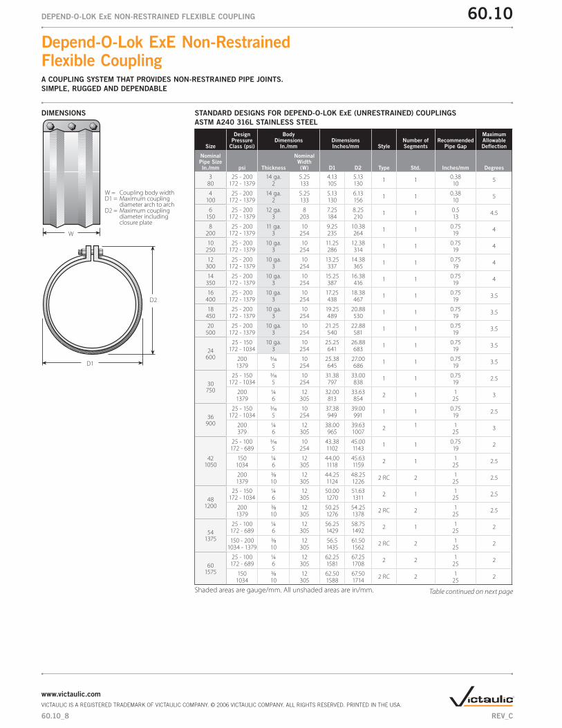
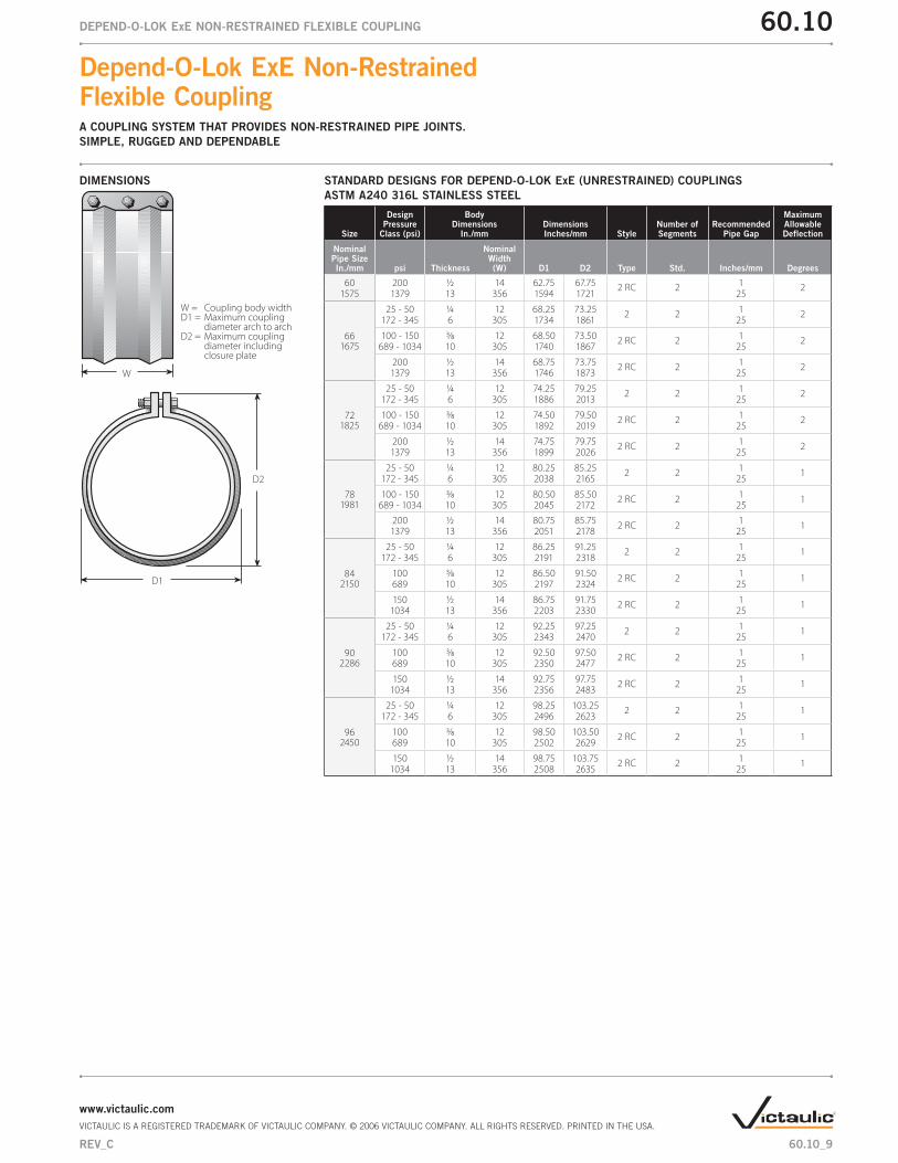
STANDARD DESIGNS FOR DEPEND-O-LOK ExE (UNRESTRAINED) COUPLINGS
ASTM A240 316L STAINLESS STEEL
Size
Design Pressure
Class (psi)
BodyDimensions
In./mmDimensionsInches/mm Style
Number of Segments
Recommended Pipe Gap
Maximum Allowable Deflection
NominalPipe SizeIn./mm psi Thickness
Nominal Width(W) D1 D2 Type Std. Inches/mm Degrees
3 25 - 200 14 ga. 5.25 4.13 5.13 1 1 0.38 580 172 - 1379 2 133 105 130 10
4 25 - 200 14 ga. 5.25 5.13 6.13 1 1 0.38 5100 172 - 1379 2 133 130 156 10
6 25 - 200 12 ga. 8 7.25 8.25 1 1 0.5 4.5150 172 - 1379 3 203 184 210 13
8 25 - 200 11 ga. 10 9.25 10.38 1 1 0.75 4200 172 - 1379 3 254 235 264 19
10 25 - 200 10 ga. 10 11.25 12.38 1 1 0.75 4250 172 - 1379 3 254 286 314 19
12 25 - 200 10 ga. 10 13.25 14.38 1 1 0.75 4300 172 - 1379 3 254 337 365 19
14 25 - 200 10 ga. 10 15.25 16.38 1 1 0.75 4350 172 - 1379 3 254 387 416 19
16 25 - 200 10 ga. 10 17.25 18.38 1 1 0.75 3.5400 172 - 1379 3 254 438 467 19
18 25 - 200 10 ga. 10 19.25 20.88 1 1 0.75 3.5450 172 - 1379 3 254 489 530 19
20 25 - 200 10 ga. 10 21.25 22.88 1 1 0.75 3.5500 172 - 1379 3 254 540 581 19
24600
25 - 150 10 ga. 10 25.25 26.88 1 1 0.75 3.5172 - 1034 3 254 641 683 19
200 3⁄16 10 25.38 27.00 1 1 0.75 3.51379 5 254 645 686 19
30750
25 - 150 3⁄16 10 31.38 33.00 1 1 0.75 2.5172 - 1034 5 254 797 838 19
200 ¼ 12 32.00 33.63 2 1 1 31379 6 305 813 854 25
36900
25 - 150 3⁄16 10 37.38 39.00 1 1 0.75 2.5172 - 1034 5 254 949 991 19
200 ¼ 12 38.00 39.63 2 1 1 3379 6 305 965 1007 25
421050
25 - 100 3⁄16 10 43.38 45.00 1 1 0.75 2172 - 689 5 254 1102 1143 19
150 ¼ 12 44.00 45.63 2 1 1 2.51034 6 305 1118 1159 25
200 3⁄8 12 44.25 48.25 2 RC 2 1 2.51379 10 305 1124 1226 25
481200
25 - 150 ¼ 12 50.00 51.632 1
12.5
172 - 1034 6 305 1270 1311 25
200 3⁄8 12 50.25 54.25 2 RC 2 1 2.51379 10 305 1276 1378 25
541375
25 - 100 ¼ 12 56.25 58.75 2 1 1 2172 - 689 6 305 1429 1492 25
150 - 200 3⁄8 12 56.5 61.50 2 RC 2 1 21034 - 1379 10 305 1435 1562 25
601575
25 - 100 ¼ 12 62.25 67.25 2 2 1 2172 - 689 6 305 1581 1708 25
150 3⁄8 12 62.50 67.50 2 RC 2 1 21034 10 305 1588 1714 25
Shaded areas are gauge/mm. All unshaded areas are in/mm. Table continued on next page
DIMENSIONS
W
D2
D1
W = Coupling body widthD1 = Maximum coupling diameter arch to archD2 = Maximum coupling diameter including closure plate
60.10_8
Depend-O-Lok ExE Non-Restrained Flexible CouplingA COUPLING SYSTEM THAT PROVIDES NON-RESTRAINED PIPE JOINTS.
SIMPLE, RUGGED AND DEPENDABLE
60.10DEPEND-O-LOK ExE NON-RESTRAINED FLEXIBLE COUPLING
www.victaulic.com
VICTAULIC IS A REGISTERED TRADEMARK OF VICTAULIC COMPANY. © 2006 VICTAULIC COMPANY. ALL RIGHTS RESERVED. PRINTED IN THE USA.
REV_C
STANDARD DESIGNS FOR DEPEND-O-LOK ExE (UNRESTRAINED) COUPLINGS
ASTM A240 316L STAINLESS STEEL
Size
Design Pressure
Class (psi)
BodyDimensions
In./mmDimensionsInches/mm Style
Number of Segments
Recommended Pipe Gap
Maximum Allowable Deflection
NominalPipe SizeIn./mm psi Thickness
Nominal Width(W) D1 D2 Type Std. Inches/mm Degrees
60 200 ½ 14 62.75 67.75 2 RC 2 1 21575 1379 13 356 1594 1721 25
661675
25 - 50 ¼ 12 68.25 73.25 2 2 1 2172 - 345 6 305 1734 1861 25
100 - 150 3⁄8 12 68.50 73.50 2 RC 2 1 2689 - 1034 10 305 1740 1867 25
200 ½ 14 68.75 73.75 2 RC 2 1 21379 13 356 1746 1873 25
721825
25 - 50 ¼ 12 74.25 79.25 2 2 1 2172 - 345 6 305 1886 2013 25
100 - 150 3⁄8 12 74.50 79.50 2 RC 2 1 2689 - 1034 10 305 1892 2019 25
200 ½ 14 74.75 79.75 2 RC 2 1 21379 13 356 1899 2026 25
781981
25 - 50 ¼ 12 80.25 85.25 2 2 1 1172 - 345 6 305 2038 2165 25
100 - 150 3⁄8 12 80.50 85.50 2 RC 2 1 1689 - 1034 10 305 2045 2172 25
200 ½ 14 80.75 85.752 RC 2
11
1379 13 356 2051 2178 25
842150
25 - 50 ¼ 12 86.25 91.25 2 2 1 1172 - 345 6 305 2191 2318 25
100 3⁄8 12 86.50 91.50 2 RC 2 1 1689 10 305 2197 2324 25
150 ½ 14 86.75 91.75 2 RC 2 1 11034 13 356 2203 2330 25
902286
25 - 50 ¼ 12 92.25 97.25 2 2 1 1172 - 345 6 305 2343 2470 25
100 3⁄8 12 92.50 97.50 2 RC 2 1 1689 10 305 2350 2477 25
150 ½ 14 92.75 97.75 2 RC 2 1 11034 13 356 2356 2483 25
962450
25 - 50 ¼ 12 98.25 103.25 2 2 1 1172 - 345 6 305 2496 2623 25
100 3⁄8 12 98.50 103.50 2 RC 2 1 1689 10 305 2502 2629 25
150 ½ 14 98.75 103.75 2 RC 2 1 11034 13 356 2508 2635 25
DIMENSIONS
W
D2
D1
W = Coupling body widthD1 = Maximum coupling diameter arch to archD2 = Maximum coupling diameter including closure plate
60.10_9
Depend-O-Lok ExE Non-Restrained Flexible CouplingA COUPLING SYSTEM THAT PROVIDES NON-RESTRAINED PIPE JOINTS.
SIMPLE, RUGGED AND DEPENDABLE
60.10DEPEND-O-LOK ExE NON-RESTRAINED FLEXIBLE COUPLING
www.victaulic.com
VICTAULIC IS A REGISTERED TRADEMARK OF VICTAULIC COMPANY. © 2006 VICTAULIC COMPANY. ALL RIGHTS RESERVED. PRINTED IN THE USA.
REV_C
STAINLESS SYSTEMS
Stainless steel pipe is becoming increasingly popular in water and wastewater treatment plant design.
Prior to 1981, stainless steel couplings were not readily available and were overly expensive. Since
then Depend-O-Lok stainless steel couplings have been available to provide owners with a total
stainless steel system at a reasonable price. Now engineers can design entire stainless steel systems
that offer long term economy without the need for carbon steel couplings or ductile iron flanges in
contact with the stainless steel pipe.
CAUTION
Due to the large volumes of air involved in jobsite air testing and the nature of pressurized
air or gas, Victaulic urges Engineers and Contractors to limit jobsite test pressure to
25 psi/175 kPa or less.
•
O-RING GASKET MATERIAL FOR AIR SERVICE
EPDM
Temperature range –30°F to +230°F/–34°C to +110°C. Excellent resistance to the deteriorative
effects of ozone, oxygen, heat and most chemicals.
Silicone
Temperature range –30°F to +350°F/–34°C to +177°C. Excellent resistance to ozone. Good
resistance to many chemicals.
Fluoroelastomer
Temperature range –20°F to +300°F/–28°C to +149°C. Outstanding resistance to heat and
chemicals.
Note: Other gasket compounds are available if required. Contact Victaulic.
•
•
•
AIR PIPING
60.10_10
Depend-O-Lok ExE Non-Restrained Flexible CouplingA COUPLING SYSTEM THAT PROVIDES NON-RESTRAINED PIPE JOINTS.
SIMPLE, RUGGED AND DEPENDABLE
60.10DEPEND-O-LOK ExE NON-RESTRAINED FLEXIBLE COUPLING
www.victaulic.com
VICTAULIC IS A REGISTERED TRADEMARK OF VICTAULIC COMPANY. © 2006 VICTAULIC COMPANY. ALL RIGHTS RESERVED. PRINTED IN THE USA.
REV_C

TESTING
Depend-O-Lok couplings are designed and built to seal air and water at a wide range of pressures.
Our couplings are randomly tested at the plant to 150 psi/1035 kPa.
STANDARD APPLICATIONS
Piping in:
Water Plants
Wastewater Plants
Force Main Piping
Slurry Lines
Penstocks
VACUUM SERVICE
The arched shape of the D-O-L body creates high section modulus. Depend-O-Lok couplings are an
excellent choice for vacuum and negative pressure (submerged) service.
O-RING GASKET MATERIAL FOR WATER & SEWAGE SERVICE
Isoprene
Temperature range –40°F to +160°F/–40°C to +71°C. Excellent resistance to water, salt water, and
sewage. Good resistance to oxygen and dilute acids.
EPDM
Temperature range –30°F to +230°F/–34°C to +110°C. Excellent resistance to water and salt
water.
Nitrile
Temperature range –20°F to +180°F/–28°C to +82°C. Excellent resistance to petroleum oils and
gasolines. Good resistance to hydrocarbons, acids and bases.
Note: Other gasket compounds are available if required. Contact Victaulic.
•
•
•
•
•
•
•
•
WATER PIPING
60.10_11
Depend-O-Lok ExE Non-Restrained Flexible CouplingA COUPLING SYSTEM THAT PROVIDES NON-RESTRAINED PIPE JOINTS.
SIMPLE, RUGGED AND DEPENDABLE
60.10DEPEND-O-LOK ExE NON-RESTRAINED FLEXIBLE COUPLING
www.victaulic.com
VICTAULIC IS A REGISTERED TRADEMARK OF VICTAULIC COMPANY. © 2006 VICTAULIC COMPANY. ALL RIGHTS RESERVED. PRINTED IN THE USA.
REV_C

WARRANTY Refer to the Warranty section of the current Price List or contact Victaulic for details.
This product shall be manufactured by Victaulic or to Victaulic specifications. All products to be
installed in accordance with current Victaulic installation/assembly instructions. Victaulic reserves the
right to change product specifications, designs and standard equipment without notice and without
incurring obligations.
NOTE
BUILT-IN GASKET
Depend-O-Lok ExE Type 2 couplings can be manufactured with the gasket assemblies built into the
coupling itself. This makes underwater installations or installations in tight quarters easier. By allow-
ing the gasket to be positioned over the pipe joint, the coupling can be closed with assurance that all
components are positioned properly and the installed coupling will be sealed tight.
SEGMENTED COUPLINGS
All ExE couplings are available in two or more segments. This offers an advantage with larger
couplings, because it reduces shipping and handling costs. Segmented couplings have the further
advantage of reducing the down time to replace a coupling on an existing pipe since the pipe does
not have to be moved to allow for a flange ring, seals, or a one-piece sleeve as with traditional sleeve
couplings.
The unique design of the coupling housing and gasket assembly makes Depend-O-Lok the most
adaptable coupling system available. It can be modified to meet a variety of special conditions your
job may experience. These adaptations include, but are not limited to:
Insulating Couplings are available to provide for isolation between two different metallic pipe
materials.
Outlet Couplings are available with flanged, threaded, grooved, or plain outlet ends. They may be
used in a wide variety of applications to reduce field labor costs. Outlet diameters up to 3" IPS
are available on 12" wide D-O-L couplings. Larger outlet diameters can be furnished by utilizing
couplings wider than standard.
Flanged Adapter Couplings are ideal for speeding field installations of flanged valves, pumps and
fittings. Depend-O-Lok products allow for considerable dimensional tolerance in the field and they
disassemble easily to facilitate removal of valves and pumps for maintenance or replacement.
DEPEND-O-LOK SPECIAL COUPLING
ASSEMBLIES
60.10
Depend-O-Lok ExE Non-Restrained Flexible CouplingA COUPLING SYSTEM THAT PROVIDES NON-RESTRAINED PIPE JOINTS.
SIMPLE, RUGGED AND DEPENDABLE
60.10DEPEND-O-LOK ExE NON-RESTRAINED FLEXIBLE COUPLING
WCAS-6TJG29
For complete contact information, visit www.victaulic.com
60.10 3746 REV B UPDATED 7/2006
VICTAULIC IS A REGISTERED TRADEMARK OF VICTAULIC COMPANY. © 2006 VICTAULIC COMPANY. ALL RIGHTS RESERVED. PRINTED IN THE USA.