restrained support and cantilever - hollowcore · restrained support and cantilever design of...
TRANSCRIPT
Restrained support and
cantileverdesign of restrained supports, preliminary design rules, design of cantilevered slabs,
unintended support restraint
Wit Derkowski, PhD, DSc
Cracow University of Technology, Poland
IPHA Technical Seminar2017, Tallinn, October 25-26, 2017
IPHA TS2017, Tallinn, October 25-26, 2017
Wit Derkowski
Restrained support and cantilever
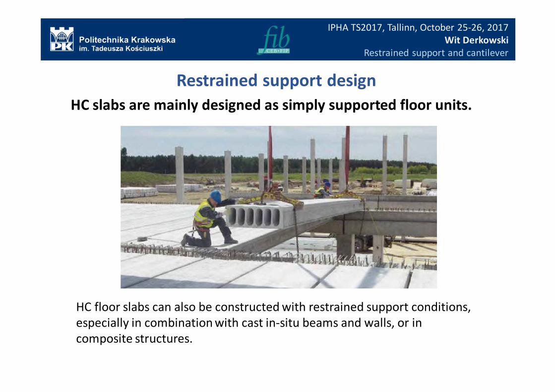
HC slabs are mainly designed as simply supported floor units.
HC floor slabs can also be constructed with restrained support conditions,
especially in combination with cast in-situ beams and walls, or in
composite structures.
Restrained support design
IPHA TS2017, Tallinn, October 25-26, 2017
Wit Derkowski
Restrained support and cantilever
Advantages of the design with floor continuity and/or restrained
support:
• Reduce the magnitude of positive sagging moment (lowering
the shear capacity), leading to shallower floor depths and/or
greater spans;
• Reduce deflections and crack widths at SLS ;
• Increase structural integrity between floor unit and support
and allow composite support connections without direct
support under the precast hollow core slabs;
• Improve diaphragm action in resisting horizontal loads (wind,
earth pressure or seismic actions).
Restrained support design
IPHA TS2017, Tallinn, October 25-26, 2017
Wit Derkowski
Restrained support and cantilever
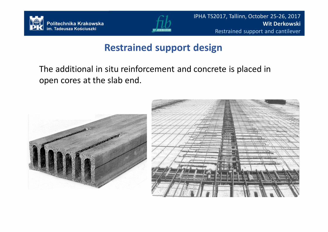
The additional in situ reinforcement and concrete is placed in
open cores at the slab end.
Restrained support design
IPHA TS2017, Tallinn, October 25-26, 2017
Wit Derkowski
Restrained support and cantilever
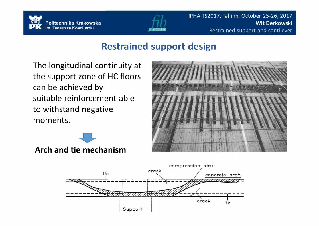
The longitudinal continuity at
the support zone of HC floors
can be achieved by
suitable reinforcement able
to withstand negative
moments.
Restrained support design
Arch and tie mechanism
IPHA TS2017, Tallinn, October 25-26, 2017
Wit Derkowski
Restrained support and cantilever
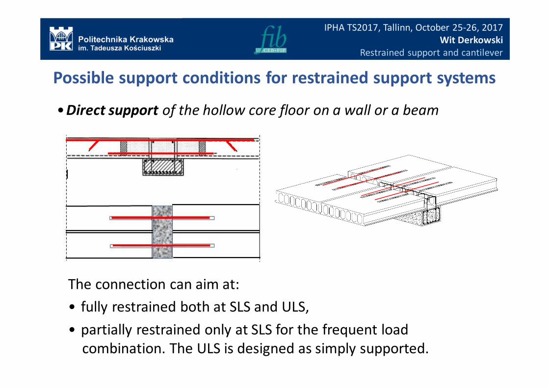
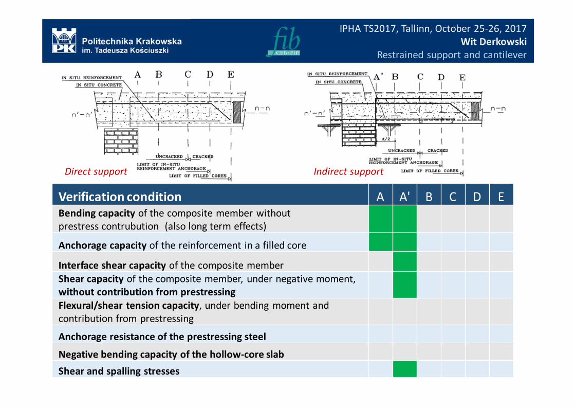
•Direct support of the hollow core floor on a wall or a beam
Possible support conditions for restrained support systems
The connection can aim at:
• fully restrained both at SLS and ULS,
• partially restrained only at SLS for the frequent load
combination. The ULS is designed as simply supported.
IPHA TS2017, Tallinn, October 25-26, 2017
Wit Derkowski
Restrained support and cantilever
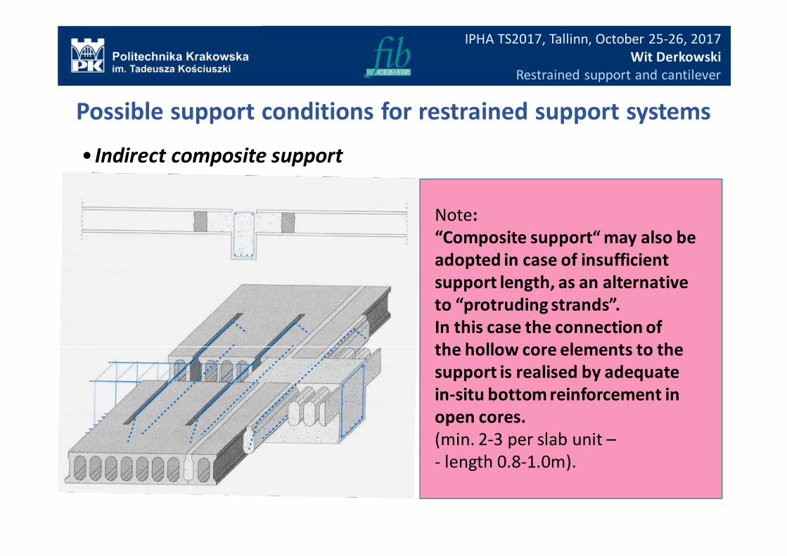
Note:
“Composite support“ may also be
adopted in case of insufficient
support length, as an alternative
to “protruding strands”.
In this case the connection of
the hollow core elements to the
support is realised by adequate
in-situ bottom reinforcement in
open cores.
(min. 2-3 per slab unit –
- length 0.8-1.0m).
• Indirect composite support
Possible support conditions for restrained support systems
IPHA TS2017, Tallinn, October 25-26, 2017
Wit Derkowski
Restrained support and cantilever
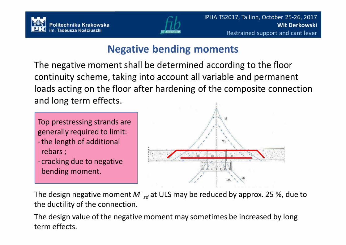
The negative moment shall be determined according to the floor
continuity scheme, taking into account all variable and permanent
loads acting on the floor after hardening of the composite connection
and long term effects.
The design negative moment M -sd at ULS may be reduced by approx. 25 %, due to
the ductility of the connection.
The design value of the negative moment may sometimes be increased by long
term effects.
Negative bending moments
Top prestressing strands are
generally required to limit:
- the length of additional
rebars ;
- cracking due to negative
bending moment.
IPHA TS2017, Tallinn, October 25-26, 2017
Wit Derkowski
Restrained support and cantilever
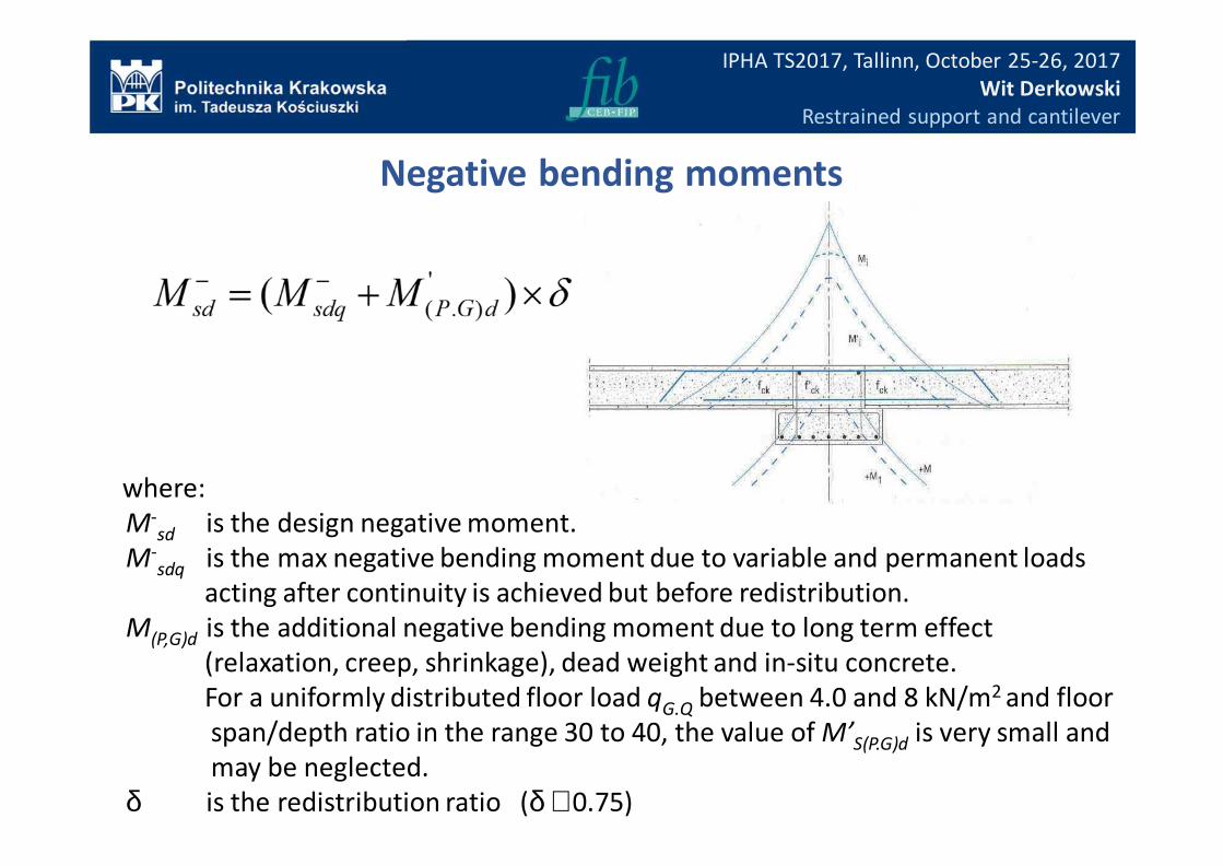
where:
M-sd is the design negative moment.
M-sdq is the max negative bending moment due to variable and permanent loads
acting after continuity is achieved but before redistribution.
M(P,G)d is the additional negative bending moment due to long term effect
(relaxation, creep, shrinkage), dead weight and in-situ concrete.
For a uniformly distributed floor load qG.Q between 4.0 and 8 kN/m2 and floor
span/depth ratio in the range 30 to 40, the value of M’S(P.G)d is very small and
may be neglected.
δ is the redistribution ratio (δ ≅ 0.75)
Negative bending moments
IPHA TS2017, Tallinn, October 25-26, 2017
Wit Derkowski
Restrained support and cantilever
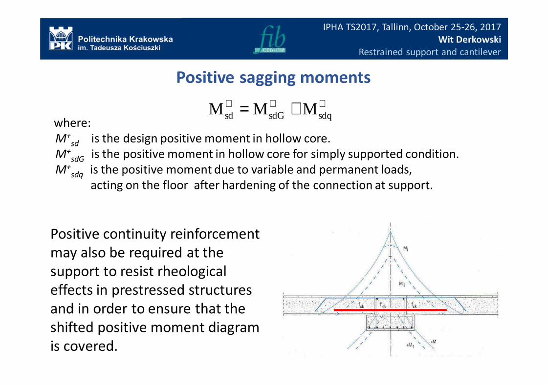
+++ += sdqsdGsd MMMwhere:
M+sd is the design positive moment in hollow core.
M+sdG is the positive moment in hollow core for simply supported condition.
M+sdq is the positive moment due to variable and permanent loads,
acting on the floor after hardening of the connection at support.
Positive continuity reinforcement
may also be required at the
support to resist rheological
effects in prestressed structures
and in order to ensure that the
shifted positive moment diagram
is covered.
Positive sagging moments
IPHA TS2017, Tallinn, October 25-26, 2017
Wit Derkowski
Restrained support and cantilever
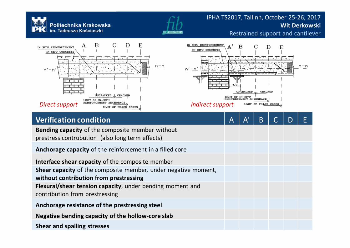
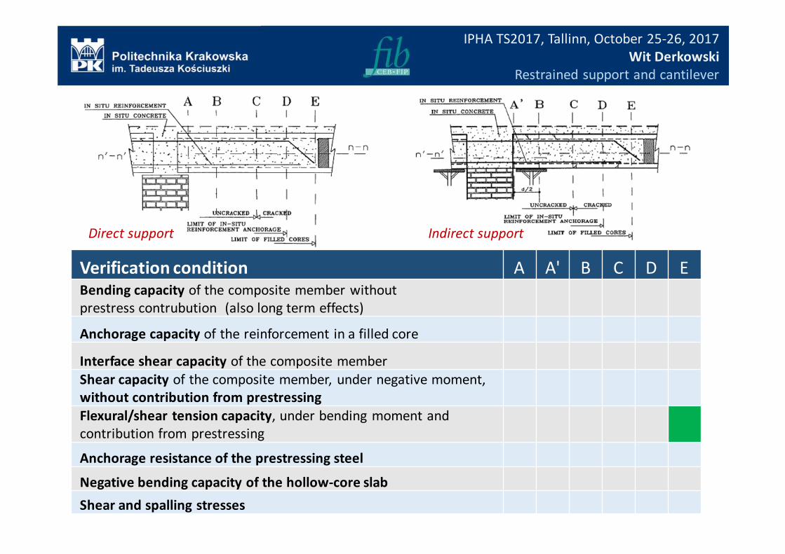
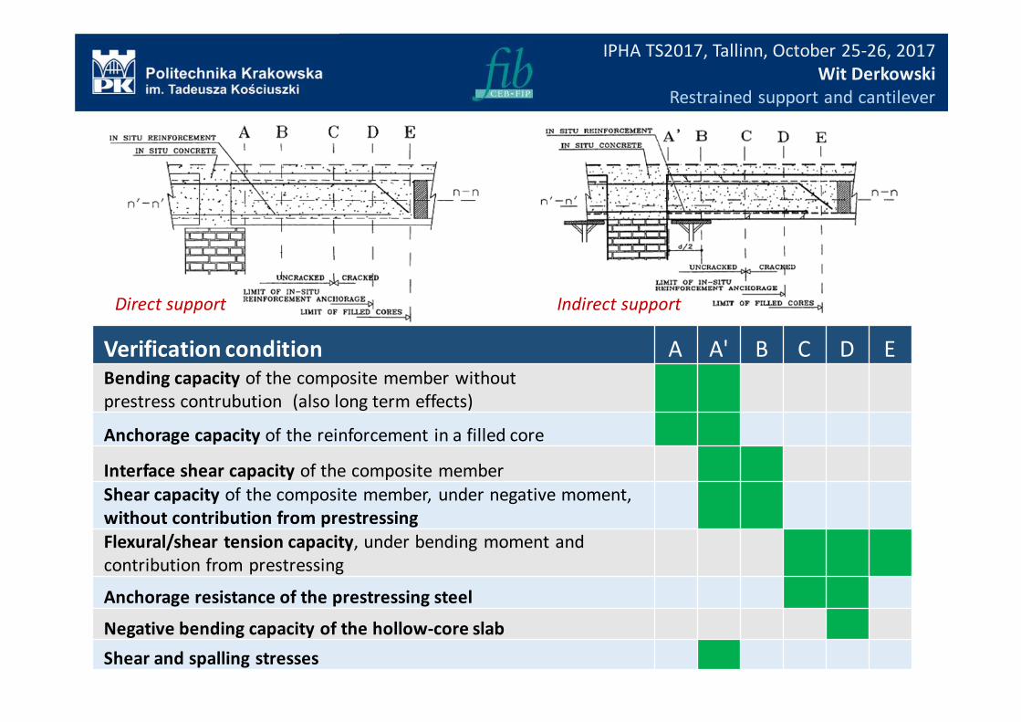
Verification condition A A' B C D E
Bending capacity of the composite member without
prestress contrubution (also long term effects)
Anchorage capacity of the reinforcement in a filled core
Interface shear capacity of the composite member
Shear capacity of the composite member, under negative moment,
without contribution from prestressing
Flexural/shear tension capacity, under bending moment and
contribution from prestressing
Anchorage resistance of the prestressing steel
Negative bending capacity of the hollow-core slab
Shear and spalling stresses
Direct support Indirect support
IPHA TS2017, Tallinn, October 25-26, 2017
Wit Derkowski
Restrained support and cantilever
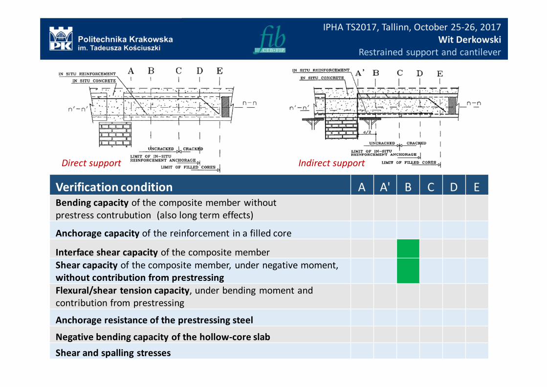
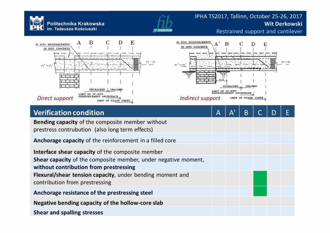
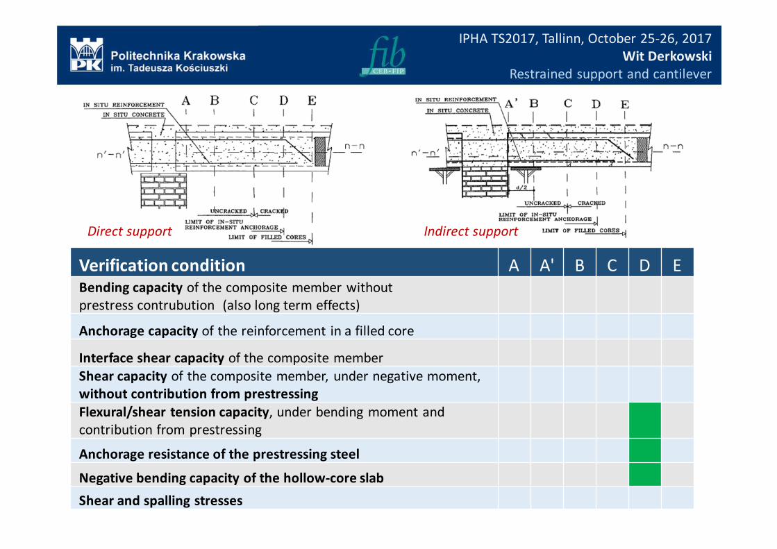
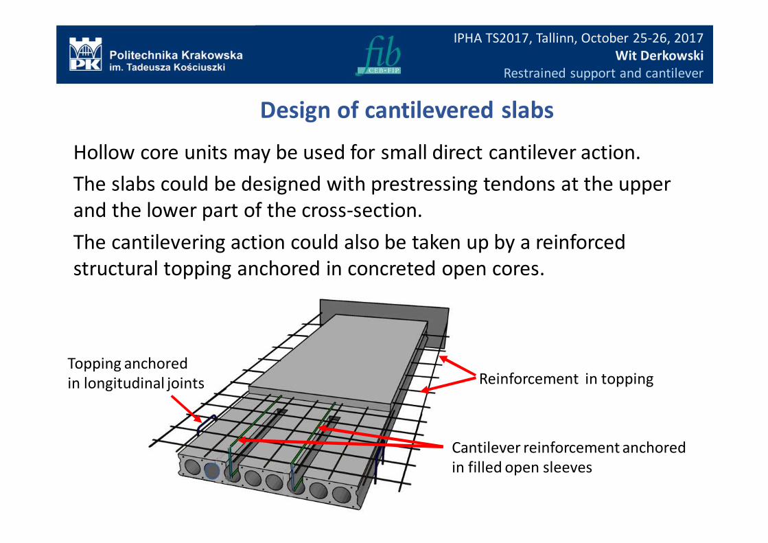
Topping anchored
in longitudinal joints Reinforcement in topping
Cantilever reinforcement anchored
in filled open sleeves
Design of cantilevered slabs
Hollow core units may be used for small direct cantilever action.
The slabs could be designed with prestressing tendons at the upper
and the lower part of the cross-section.
The cantilevering action could also be taken up by a reinforced
structural topping anchored in concreted open cores.
IPHA TS2017, Tallinn, October 25-26, 2017
Wit Derkowski
Restrained support and cantilever
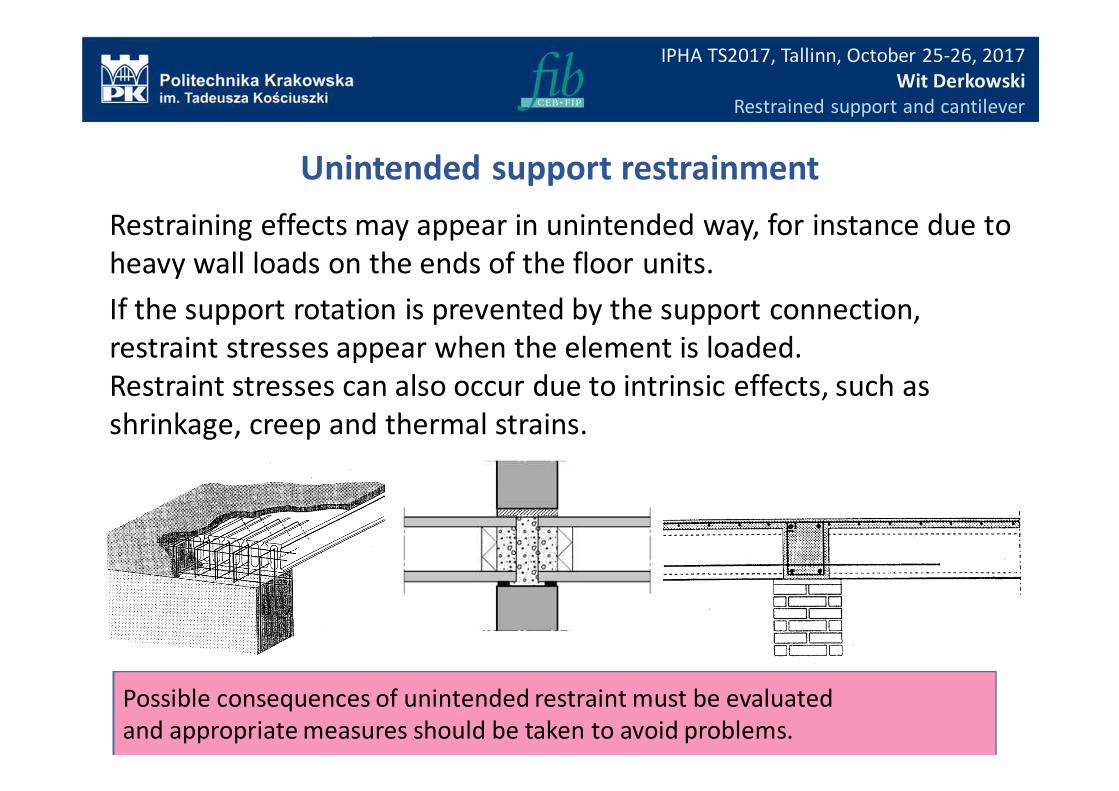
Unintended support restrainment
Restraining effects may appear in unintended way, for instance due to
heavy wall loads on the ends of the floor units.
If the support rotation is prevented by the support connection,
restraint stresses appear when the element is loaded.
Restraint stresses can also occur due to intrinsic effects, such as
shrinkage, creep and thermal strains.
Possible consequences of unintended restraint must be evaluated
and appropriate measures should be taken to avoid problems.
IPHA TS2017, Tallinn, October 25-26, 2017
Wit Derkowski
Restrained support and cantilever
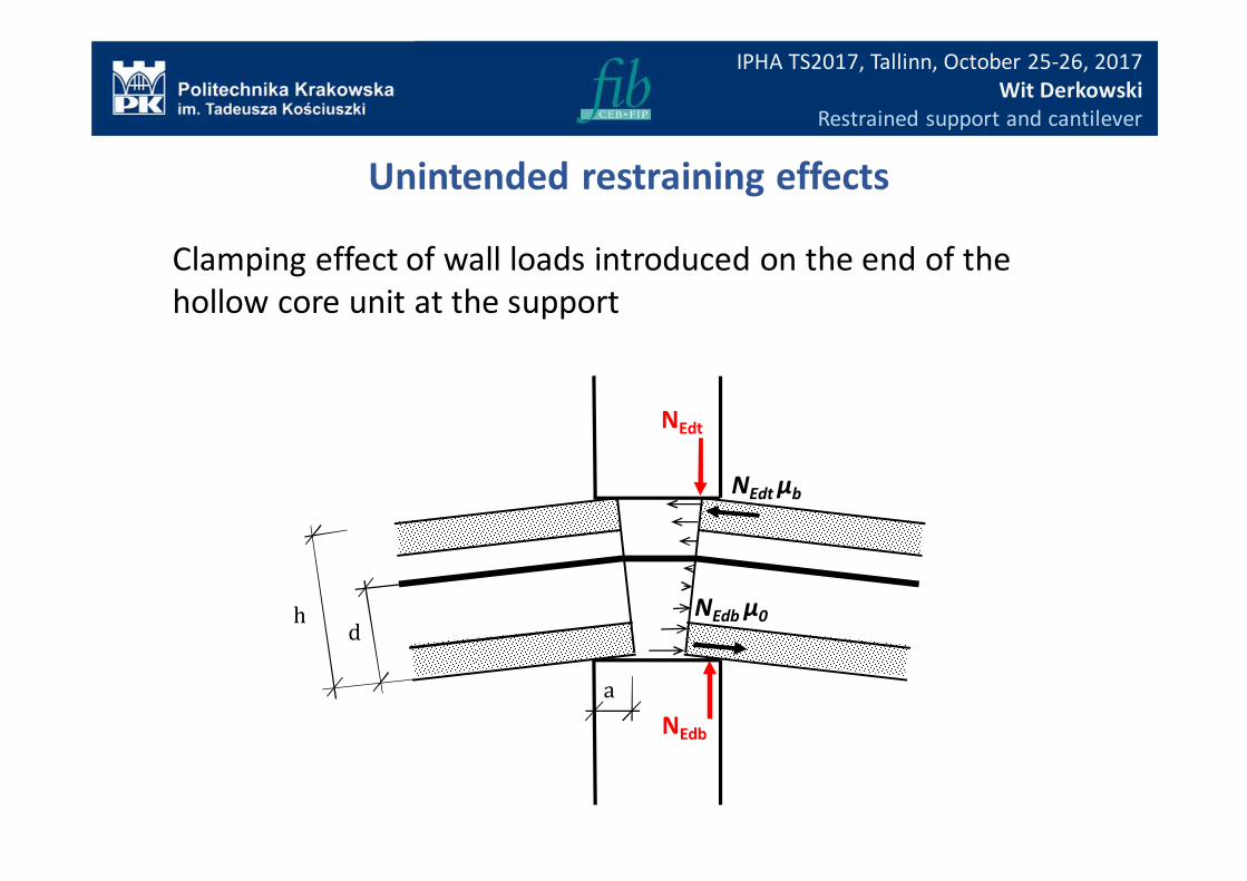
Clamping effect of wall loads introduced on the end of the
hollow core unit at the support
Unintended restraining effects
NEdt μb
NEdt
NEdb
a
hd
NEdb μ0
IPHA TS2017, Tallinn, October 25-26, 2017
Wit Derkowski
Restrained support and cantilever
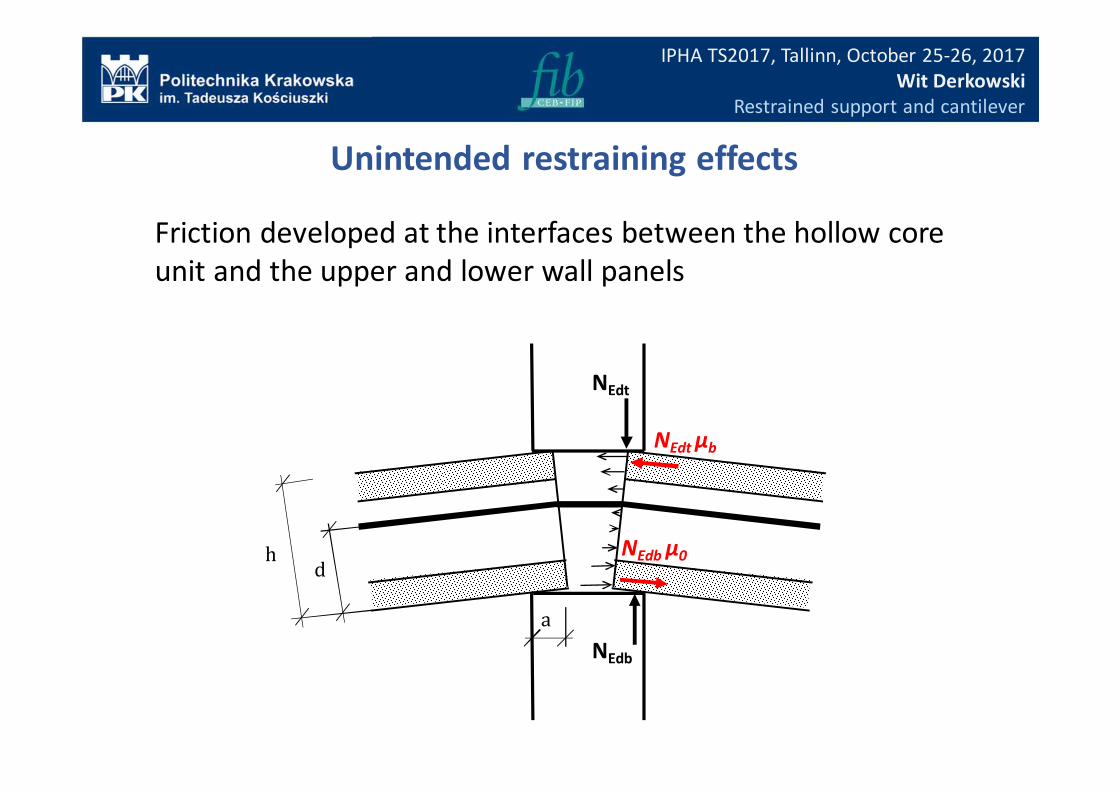
Friction developed at the interfaces between the hollow core
unit and the upper and lower wall panels
Unintended restraining effects
NEdt μb
NEdt
NEdb
a
hd
NEdb μ0
IPHA TS2017, Tallinn, October 25-26, 2017
Wit Derkowski
Restrained support and cantilever
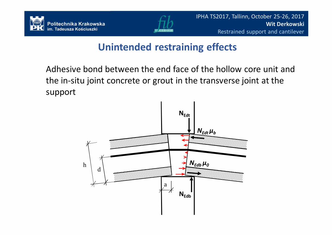
Adhesive bond between the end face of the hollow core unit and
the in-situ joint concrete or grout in the transverse joint at the
support
Unintended restraining effects
NEdt μb
NEdt
NEdb
a
hd
NEdb μ0
IPHA TS2017, Tallinn, October 25-26, 2017
Wit Derkowski
Restrained support and cantilever
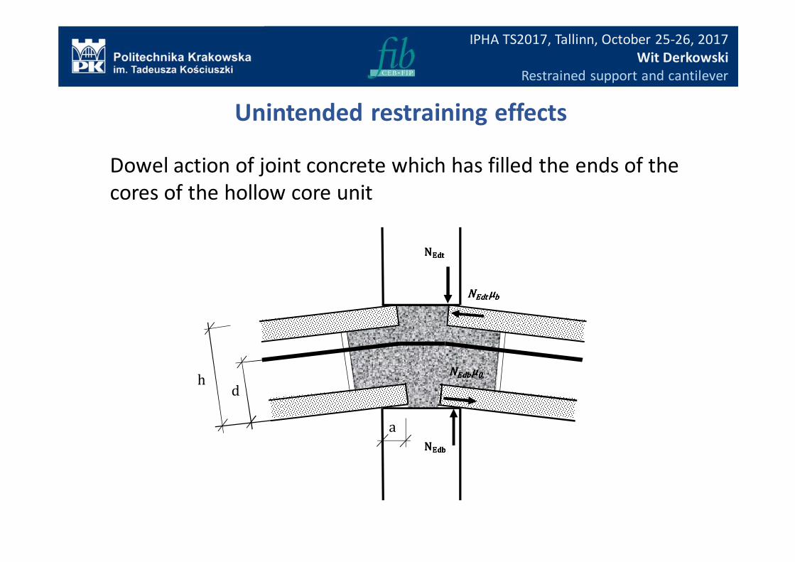
Dowel action of joint concrete which has filled the ends of the
cores of the hollow core unit
Unintended restraining effects
NNNNEdt Edt Edt Edt μμμμbbbb
NNNNEdtEdtEdtEdt
NNNNEdbEdbEdbEdb
a
hd
NNNNEdb Edb Edb Edb μμμμ0000
IPHA TS2017, Tallinn, October 25-26, 2017
Wit Derkowski
Restrained support and cantilever
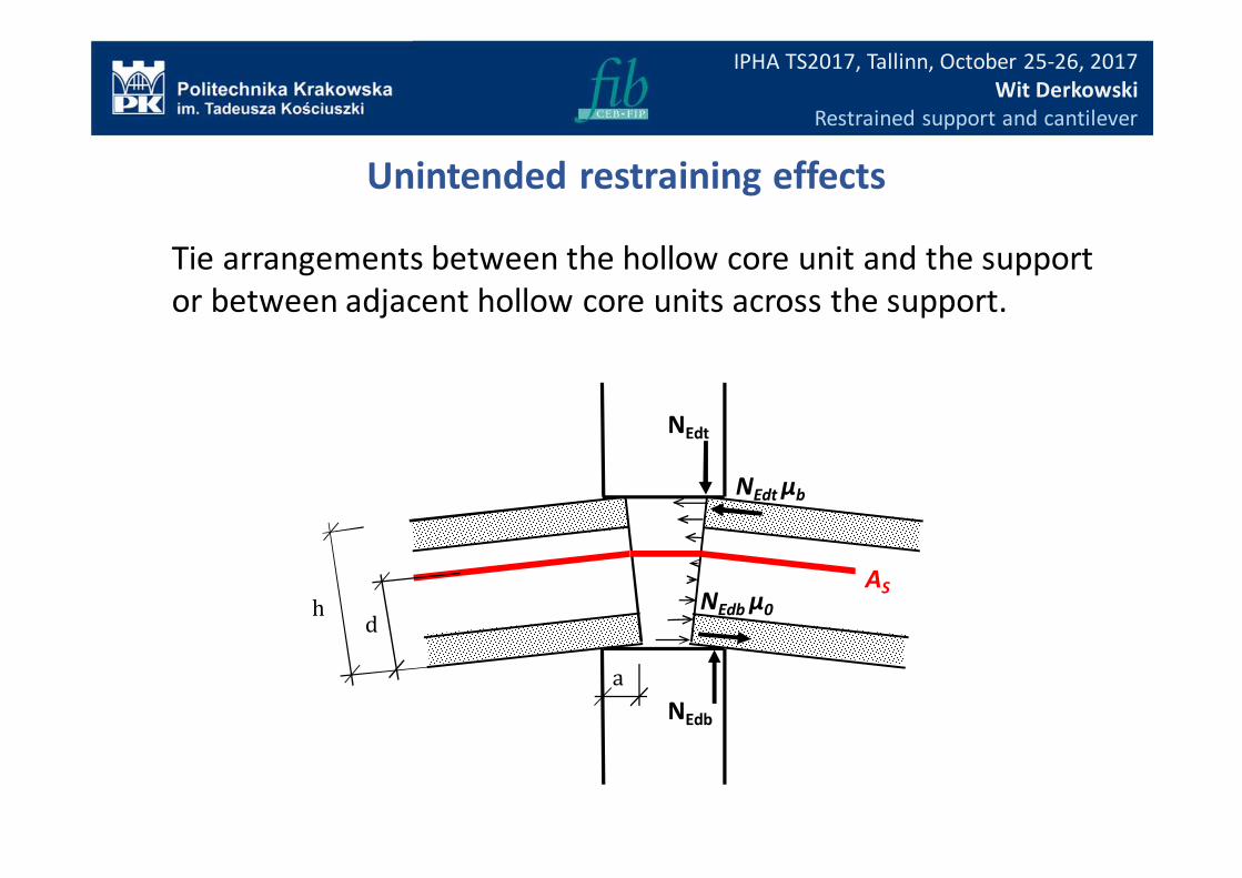
Tie arrangements between the hollow core unit and the support
or between adjacent hollow core units across the support.
Unintended restraining effects
NEdt μb
NEdt
NEdb
a
hd
NEdb μ0
AS
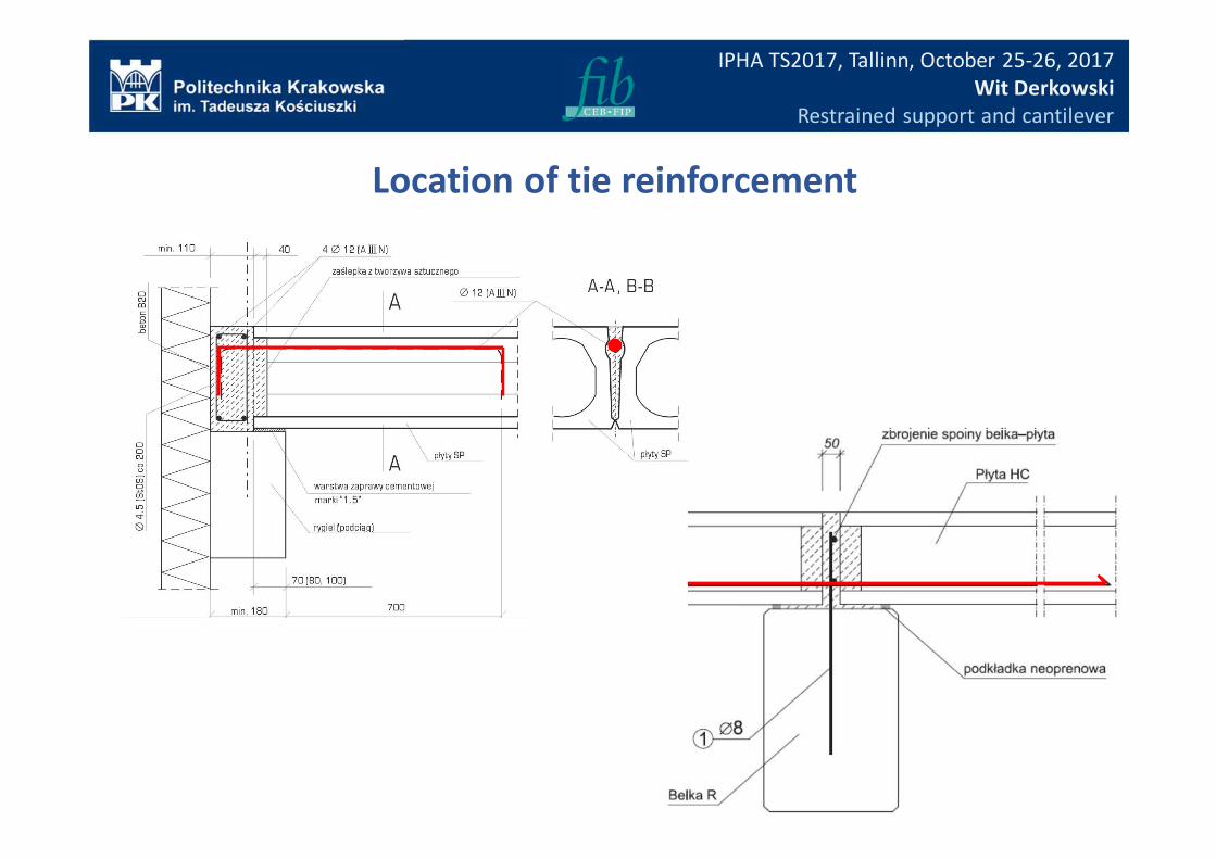
Location of tie reinforcement
IPHA TS2017, Tallinn, October 25-26, 2017
Wit Derkowski
Restrained support and cantilever
(((( ))))
−−−−++++==== )()(
)()( 2 yfyf
yS
yIbV cpctdcpctd
c
wRdc ττττσσσσ
(((( ))))yYI
MlP
I
YpYyY
Ay c
Edn
txt
tcccp −−−−⋅⋅⋅⋅−−−−
⋅⋅⋅⋅
−−−−−−−−++++====∑∑∑∑====1
)())((1
)(σσσσ
∑∑∑∑====
⋅⋅⋅⋅
++++−−−−⋅⋅⋅⋅−−−−⋅⋅⋅⋅====
n
t
xtt
tccc
wcp dx
ldPyCp
I
YpYyS
A
yA
yby
1
)()(
)()()()(
1)(ττττ
13/16
IPHA TS2017, Tallinn, October 25-26, 2017
Wit Derkowski
Restrained support and cantilever
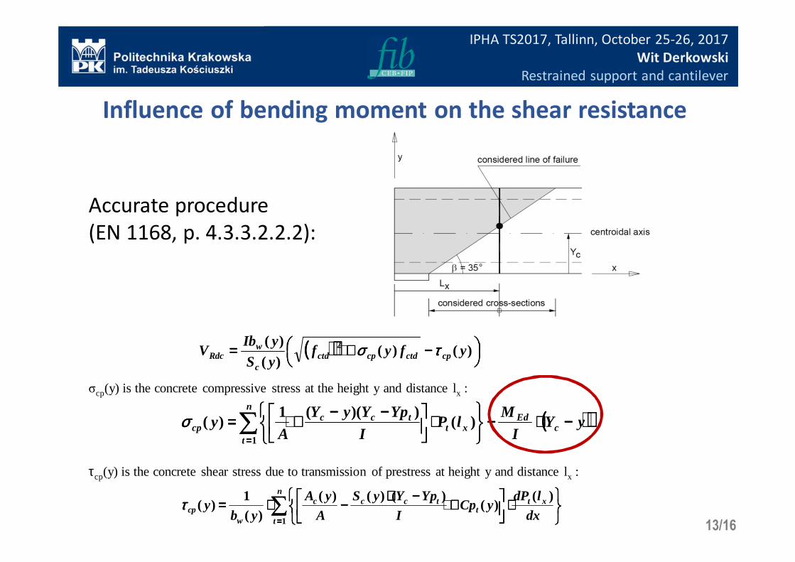
Accurate procedure
(EN 1168, p. 4.3.3.2.2.2):
τcp(y) is the concrete shear stress due to transmission of prestress at height y and distance lx :
σcp(y) is the concrete compressive stress at the height y and distance lx :
Influence of bending moment on the shear resistance
IPHA TS2017, Tallinn, October 25-26, 2017
Wit Derkowski
Restrained support and cantilever
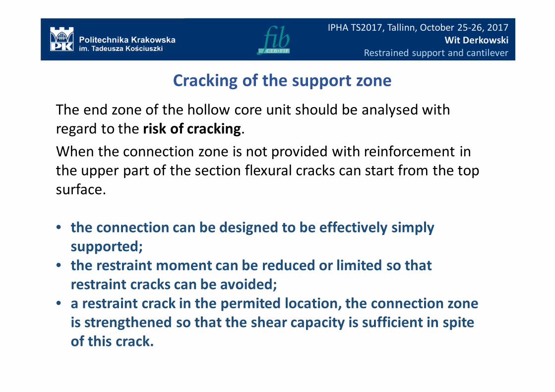
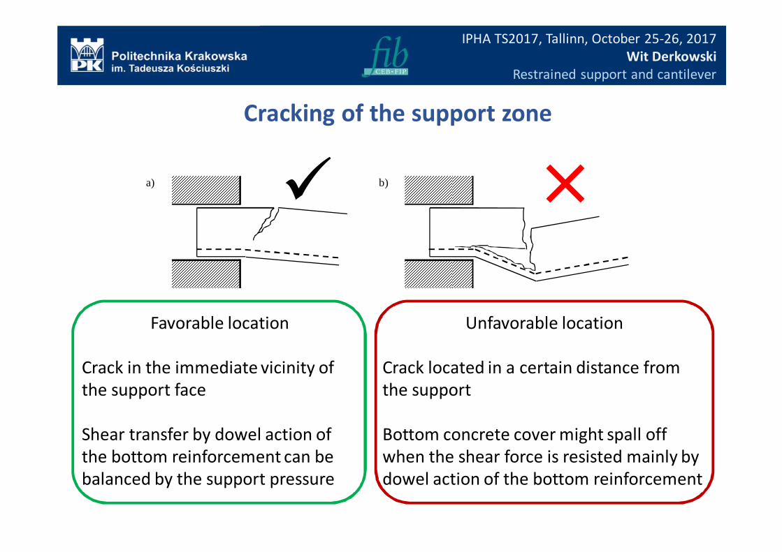
The end zone of the hollow core unit should be analysed with
regard to the risk of cracking.
When the connection zone is not provided with reinforcement in
the upper part of the section flexural cracks can start from the top
surface.
• the connection can be designed to be effectively simply
supported;
• the restraint moment can be reduced or limited so that
restraint cracks can be avoided;
• a restraint crack in the permited location, the connection zone
is strengthened so that the shear capacity is sufficient in spite
of this crack.
Cracking of the support zone
IPHA TS2017, Tallinn, October 25-26, 2017
Wit Derkowski
Restrained support and cantilever
Unfavorable location
Crack located in a certain distance from
the support
Bottom concrete cover might spall off
when the shear force is resisted mainly by
dowel action of the bottom reinforcement
Favorable location
Crack in the immediate vicinity of
the support face
Shear transfer by dowel action of
the bottom reinforcement can be
balanced by the support pressure
a) b)
Cracking of the support zone
�
IPHA TS2017, Tallinn, October 25-26, 2017
Wit Derkowski
Restrained support and cantilever
• restraint moment can be reduced by limiting the load on the wall;
• the concrete fill in cores without tie bars should not extend outside
the wall;
• tie bars anchored in cores or longitudinal joints should not be cut
off within the critical region;
• slanted ends of the hollow core slabs are proposed
Ways to reduce the risk of cracking
�
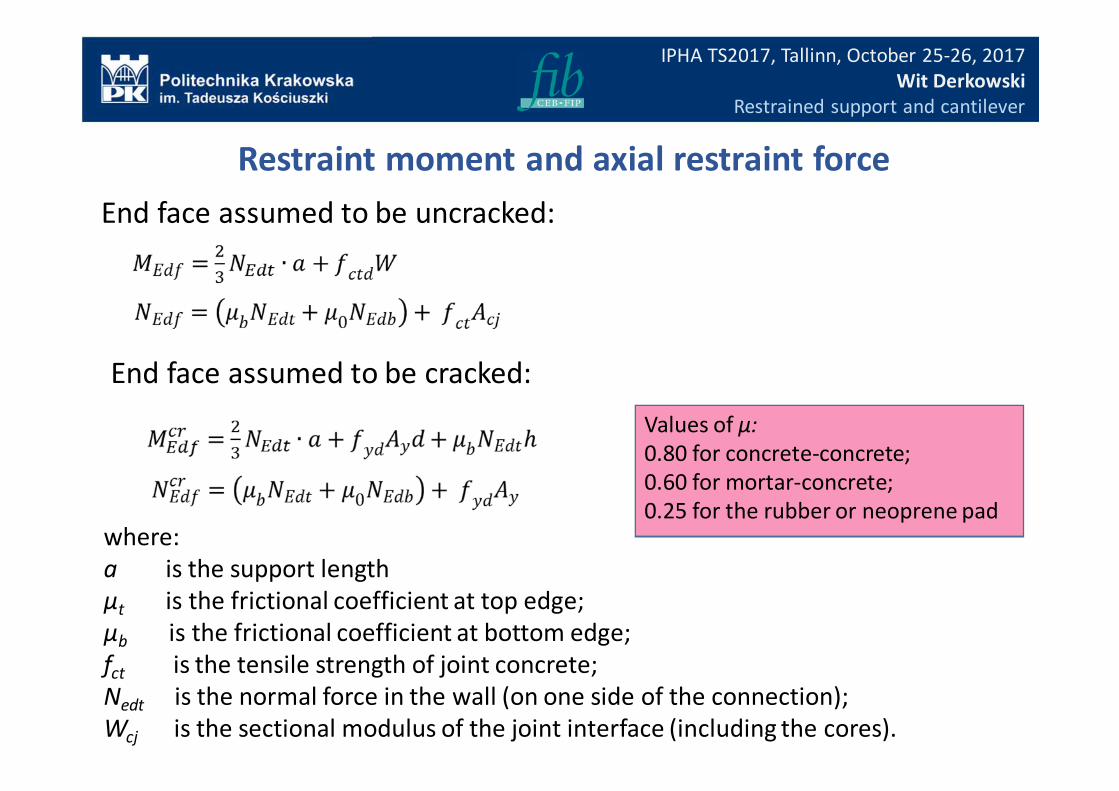
Restraint moment and axial restraint force
End face assumed to be uncracked:
End face assumed to be cracked:
IPHA TS2017, Tallinn, October 25-26, 2017
Wit Derkowski
Restrained support and cantilever
where:
a is the support length
µt is the frictional coefficient at top edge;
µb is the frictional coefficient at bottom edge;
fct is the tensile strength of joint concrete;
Nedt is the normal force in the wall (on one side of the connection);
Wcj is the sectional modulus of the joint interface (including the cores).
Values of µ:
0.80 for concrete-concrete;
0.60 for mortar-concrete;
0.25 for the rubber or neoprene pad
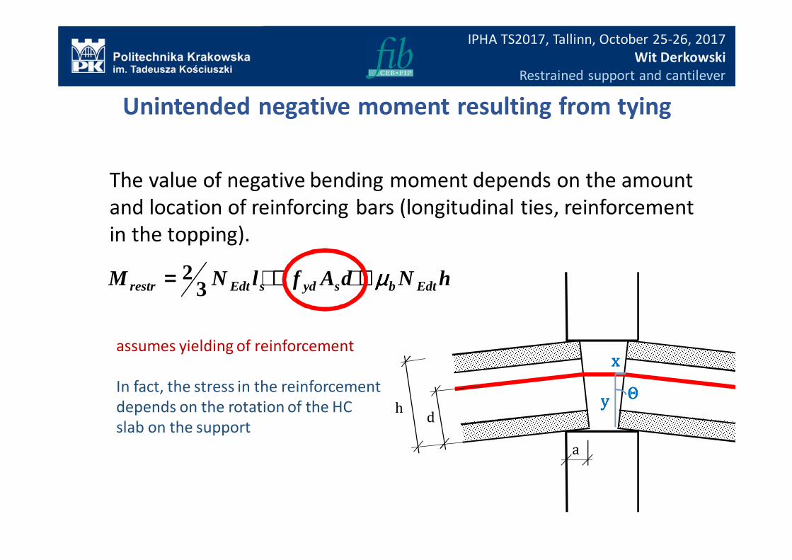
Unintended negative moment resulting from tying
The value of negative bending moment depends on the amount
and location of reinforcing bars (longitudinal ties, reinforcement
in the topping).
hNdAflNM EdtbsydsEdtrestr µµµµ++++++++==== 32
IPHA TS2017, Tallinn, October 25-26, 2017
Wit Derkowski
Restrained support and cantilever
ΘΘΘΘ
xxxx
yyyy
a
hd
assumes yielding of reinforcement
In fact, the stress in the reinforcement
depends on the rotation of the HC
slab on the support
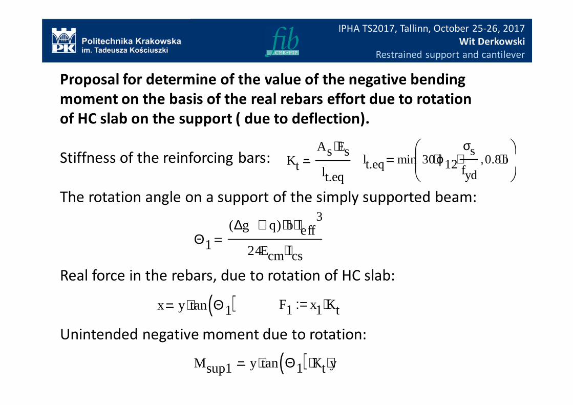
Proposal for determine of the value of the negative bending
moment on the basis of the real rebars effort due to rotation
of HC slab on the support ( due to deflection).
Stiffness of the reinforcing bars:
The rotation angle on a support of the simply supported beam:
Real force in the rebars, due to rotation of HC slab:
Unintended negative moment due to rotation:
F1 x1 Kt⋅:=
Θ1
∆g q+( ) b⋅ leff3
⋅
24Ecm Ics⋅
Msup1 y tan Θ1( )⋅ Kt⋅ y⋅
x y tan Θ1( )⋅
lt.eq min 30ϕ12⋅σs
fyd⋅ 0.8b⋅,
Kt
As Es⋅
lt.eq
IPHA TS2017, Tallinn, October 25-26, 2017
Wit Derkowski
Restrained support and cantilever
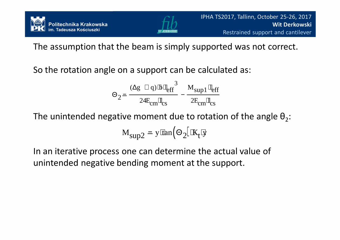
The assumption that the beam is simply supported was not correct.
So the rotation angle on a support can be calculated as:
The unintended negative moment due to rotation of the angle θ2:
In an iterative process one can determine the actual value of
unintended negative bending moment at the support.
Θ2
∆g q+( ) b⋅ leff3⋅
24Ecm Ics⋅
Msup1 leff⋅
2Ecm Ics⋅−
Msup2 y tan Θ2( )⋅ Kt⋅ y⋅
IPHA TS2017, Tallinn, October 25-26, 2017
Wit Derkowski
Restrained support and cantilever
IPHA TS2017, Tallinn, October 25-26, 2017
Wit Derkowski
Restrained support and cantilever
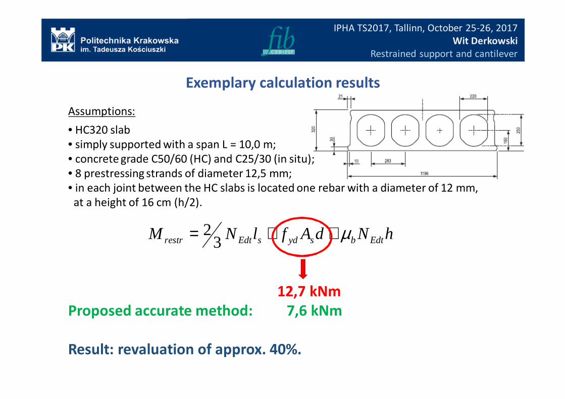
Assumptions:
• HC320 slab
• simply supported with a span L = 10,0 m;
• concrete grade C50/60 (HC) and C25/30 (in situ);
• 8 prestressing strands of diameter 12,5 mm;
• in each joint between the HC slabs is located one rebar with a diameter of 12 mm,
at a height of 16 cm (h/2).
Exemplary calculation results
hNdAflNM EdtbsydsEdtrestr µ++= 32
12,7 kNm
Proposed accurate method: 7,6 kNm
Result: revaluation of approx. 40%.
IPHA TS2017, Tallinn, October 25-26, 2017
Wit Derkowski
Restrained support and cantilever
Thank you,