6. modelling and analysis josef machacek czech technical university in prague
TRANSCRIPT

6. Modelling and analysis
Josef Machacek
Czech Technical University in Prague

2Lecture 6, V001, April 09
Objectives
• This lecture describes principles of modelling and analysis of structures.
• Global analyses distinguishing effects of deformed geometry and material non-linearities are presented.
• Survey of both simple and FEM analyses and modelling are shown.
• Finally some basic examples are presented.
Objectives
Basic requirements
Methods of analysis
Influence of deformed geometry
Influence of material
behaviour
Assessment 1
Simple global modelling
FE modelling
Assessment 2
Examples
Conclusions
Notes

3Lecture 6, V001, April 09
Outline of the lecture
1. Basic requirements
2. Methods of analysis
3. Influence of deformed geometry
4. Influence of material behaviour
5. Simple global modelling of frames, trusses and beams
6. FE modelling
7. Examples
8. Conclusions
Objectives
Basic requirements
Methods of analysis
Influence of deformed geometry
Influence of material
behaviour
Assessment 1
Simple global modelling
FE modelling
Assessment 2
Examples
Conclusions
Notes

4Lecture 6, V001, April 09
1. Basic requirements
• Calculation model should reflect real global and local behaviour of the designed structure (members, cross sections, joints and placement).
• Analysis should correspond to limit states under consideration: ULS (ultimate limit states) or SLS (serviceability limit states), i.e. with appropriate loading, criteria and reliability.
Objectives
Basic requirements
Methods of analysis
Influence of deformed geometry
Influence of material
behaviour
Assessment 1
Simple global modelling
FE modelling
Assessment 2
Examples
Conclusions
Notes

5Lecture 6, V001, April 09
1. Basic requirements
• Joints are generally modelled (in accordance with EN 1993-1-8) as: – simple (transmitting no bending moments),– continuous (with rigidity and resistance providing full
continuity of elements),– semi-continues (in which the joint behaviour needs to
be considered in the global analysis).
• Ground-structure interaction should be considered in case of significant ground support deformation (see EN 1997).
Objectives
Basic requirements
Methods of analysis
Influence of deformed geometry
Influence of material
behaviour
Assessment 1
Simple global modelling
FE modelling
Assessment 2
Examples
Conclusions
Notes

6Lecture 6, V001, April 09
2. Methods of analysis
Simplified scheme of calculation models:
geometrically non-linear(2nd order)
linear analysis(1st order, elastic)
strength
fibre plasticity
plastic analysis
δ
F elastic analysis
collapse
e
Imperfections (global, local), e.g.:
e
Objectives
Basic requirements
Methods of analysis
Influence of deformed geometry
Influence of material
behaviour
Assessment 1
Simple global modelling
FE modelling
Assessment 2
Examples
Conclusions
Notes

7Lecture 6, V001, April 09
2. Methods of analysis
General types of analysis:Elastic
LA: Linear elastic analysis;
LBA: Linear bifurcation analysis;
GNA: Geometrically non-linear analysis.
Non-Elastic
MNA: Materially non-linear analysis;
GMNA: Geometrically and materially non-linear analysis;
GNIA: Geometrically non-linear analysis elastic with imperfections included;
GMNIA: Geometrically and materially non-linear analysis with imperfections included.
Objectives
Basic requirements
Methods of analysis
Influence of deformed geometry
Influence of material
behaviour
Assessment 1
Simple global modelling
FE modelling
Assessment 2
Examples
Conclusions
Notes

8Lecture 6, V001, April 09
2. Methods of analysis
Simplified GNA (using equilibrium equation on
deformed structure but the same “small
deflections” as in common LA) is called 2nd order
analysis. Such analysis is usually sufficient for
investigation of buckling in steel frame structures.
Objectives
Basic requirements
Methods of analysis
Influence of deformed geometry
Influence of material
behaviour
Assessment 1
Simple global modelling
FE modelling
Assessment 2
Examples
Conclusions
Notes

9Lecture 6, V001, April 09
3. Influence of deformed geometry
Simplified scheme of elastic analyses:
δ
F
e
LA
LBA
GNAGNIA
Fcr
Objectives
Basic requirements
Methods of analysis
Influence of deformed geometry
Influence of material
behaviour
Assessment 1
Simple global modelling
FE modelling
Assessment 2
Examples
Conclusions
Notes

10Lecture 6, V001, April 09
3. Influence of deformed geometry
• LA (1st order analysis):
Benefits:
Superposition valid, easy.
Drawbacks:
Approximate solution, necessary to include
imperfections (global, local) and 2nd order
effects in other ways (by reduction coefficients
for buckling).
Objectives
Basic requirements
Methods of analysis
Influence of deformed geometry
Influence of material
behaviour
Assessment 1
Simple global modelling
FE modelling
Assessment 2
Examples
Conclusions
Notes

11Lecture 6, V001, April 09
3. Influence of deformed geometry
• LBA (linear bifurcation analysis):
This analysis uses 2nd order analysis, introducing, however, zero initial imperfections and zero non-axial loading. The resulting critical forces are expressed in the form
Ncr,i = cr,iNEd where i Є(1; ∞)
(NEd represent initial set of axial forces)
Note: In non-linear bifurcation analysis the GNIA is used and bifurcation occurs by snap-through of initial imperfection shape.
Objectives
Basic requirements
Methods of analysis
Influence of deformed geometry
Influence of material
behaviour
Assessment 1
Simple global modelling
FE modelling
Assessment 2
Examples
Conclusions
Notes

12Lecture 6, V001, April 09
3. Influence of deformed geometry
• GNA, GNIA (or 2nd order analysis):
Benefits:
Direct solution of elastic buckling,
covers behaviour of cables.
Drawbacks:
Superposition can not be used,
software necessary.
Objectives
Basic requirements
Methods of analysis
Influence of deformed geometry
Influence of material
behaviour
Assessment 1
Simple global modelling
FE modelling
Assessment 2
Examples
Conclusions
Notes

13Lecture 6, V001, April 09
4. Influence of material behaviour
Simplified scheme of plastic analyses:
Frigid-plastic analysis
non-linear plasticanalysis
elastic-plastic analysis
fibre plasticity
plastic hinge
Objectives
Basic requirements
Methods of analysis
Influence of deformed geometry
Influence of material
behaviour
Assessment 1
Simple global modelling
FE modelling
Assessment 2
Examples
Conclusions
Notes

14Lecture 6, V001, April 09
4. Influence of material behaviour
• MNA (plastic analysis):
Benefits:
Higher strength capacity.
Drawbacks:
May only be used provided that: - steel is sufficiently ductile (fu/fy ≥ 1.1; ≥ 15 %;
εu ≥ 15 εy);
- for global analysis the cross sections are of class 1;
- in global analysis the stability of members at plastic
hinges is assured;
- software for plastic global analysis is desirable.
Objectives
Basic requirements
Methods of analysis
Influence of deformed geometry
Influence of material
behaviour
Assessment 1
Simple global modelling
FE modelling
Assessment 2
Examples
Conclusions
Notes

15Lecture 6, V001, April 09
4. Influence of material behaviour
Modelling of material behaviour:
E/10000or similar small value(just for numerical reasons)
true stress-straincurve
stress-strain curvefrom tests (using original dimension of test coupon)
Objectives
Basic requirements
Methods of analysis
Influence of deformed geometry
Influence of material
behaviour
Assessment 1
Simple global modelling
FE modelling
Assessment 2
Examples
Conclusions
Notes
• without hardening
• with hardening

16Lecture 6, V001, April 09
5. Influence of material behaviour
Plastic global analysis models:
• non-linear plastic analysis considering the partial plastification of members in plastic zones,
• elastic-plastic analysis with plastified sections and/or joints as plastic hinges,
• rigid-plastic analysis neglecting the elastic behaviour between hinges.
Objectives
Basic requirements
Methods of analysis
Influence of deformed geometry
Influence of material
behaviour
Assessment 1
Simple global modelling
FE modelling
Assessment 2
Examples
Conclusions
Notes

17Lecture 6, V001, April 09
Formative Assessment Question 1
• Describe types of analyses.
• How 2nd order effects in compression members may be covered?
• Describe modelling of material properties.
• What are the limits for using an elastic analysis?
• What are the prerequisites for using a plastic analysis?
Objectives
Basic requirements
Methods of analysis
Influence of deformed geometry
Influence of material
behaviour
Assessment 1
Simple global modelling
FE modelling
Assessment 2
Examples
Conclusions
Notes

18Lecture 6, V001, April 09
5. Simple modelling of structures
5.1 Frame stability:• First order elastic frames
if (using LBA or approx.
formula)
10Ed
cr F
Fcr
Lcr ≤ hLcr ≤ h
as if withfictitioussupports
h h
Critical length is lesser than or equal to system length.
Objectives
Basic requirements
Methods of analysis
Influence of deformed geometry
Influence of material
behaviour
Assessment 1
Simple global modelling
FE modelling
Assessment 2
Examples
Conclusions
Notes

19Lecture 6, V001, April 09
5. Simple modelling of structures
Note: Instead of using LBA, approximate value of cr may be determined from analysis of a compression member withan elastic sway brace:
Ed
crcr V
V
EdH,Ed
Edcr
h
V
H
hHV EdEdH,cr
swaybuckling mode
non-sway buckling mode (Euler’s critical load)
cH EdH,Ed
Ecr VV
stiffness c < c
EdH,
2
2
E h
IEV
stiffness c < c LL
h
crV Ecr VV
EdH
For sway buckling mode:
Therefore, for sway buckling mode:
Objectives
Basic requirements
Methods of analysis
Influence of deformed geometry
Influence of material
behaviour
Assessment 1
Simple global modelling
FE modelling
Assessment 2
Examples
Conclusions
Notes
20Lecture 6, V001, April 09
5. Simple modelling of structures
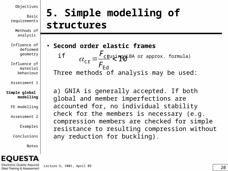
• Second order elastic frames
if (using LBA or approx. formula)
Three methods of analysis may be used:
a) GNIA is generally accepted. If both global and member imperfections are accounted for, no individual stability check for the members is necessary (e.g. compression members are checked for simple resistance to resulting compression without any reduction for buckling).
10Ed
cr F
Fcr
Objectives
Basic requirements
Methods of analysis
Influence of deformed geometry
Influence of material
behaviour
Assessment 1
Simple global modelling
FE modelling
Assessment 2
Examples
Conclusions
Notes

21Lecture 6, V001, April 09
5. Simple modelling of structures
b) GNA for global analysis of the structure with global imperfections. Member stability checks should be based on buckling lengths equal to the system lengths. If and sway buckling mode is predominant, as a good approximation an amplified LA may be used (see Eurocode 3, cl. 5.2.2(5B)) where sway effects (i.e. all horizontal loading) should be increased by a multiple
103 cr
Objectives
Basic requirements
Methods of analysis
Influence of deformed geometry
Influence of material
behaviour
Assessment 1
Simple global modelling
FE modelling
Assessment 2
Examples
Conclusions
Notes
cr
11
1
Note: For multi-storey frames thissimplification can be used
provided they are ”regular”(see Eurocode, cl. 5.2.2(6B)

22Lecture 6, V001, April 09
5. Simple modelling of structures
c) LA for global analysis without considering imperfections. Member stability checks should be based on buckling lengths equal to the global buckling length (received from LBA):
orLcr > h
Edcr
y
cr
y
N
fA
N
N
Edcr
y2
cr
2
N
IE
N
IELcr
Objectives
Basic requirements
Methods of analysis
Influence of deformed geometry
Influence of material
behaviour
Assessment 1
Simple global modelling
FE modelling
Assessment 2
Examples
Conclusions
Notes Note: Safe use of this method requires increasing ofmoments due to sway effects (approx. by 20 %).

23Lecture 6, V001, April 09
5. Simple modelling of structures
Objectives
Basic requirements
Methods of analysis
Influence of deformed geometry
Influence of material
behaviour
Assessment 1
Simple global modelling
FE modelling
Assessment 2
Examples
Conclusions
Notes
5.2 Trusses – common LA:– Approximate analysis assuming pin-jointed member
ends (secondary moments in members due to stiffness of joints ignored):
– Approximate analysis with continuous chords
(usual analysis):

24Lecture 6, V001, April 09
– eccentricity of members in nodes should be limited
(see EN 1993-1-8, cl. 5.1.5), otherwise eccentricity moments shall be distributed
to members.
– effects of global and local instabilities in trusses in accordance with cr (global instability is usually
negligible, unless slender truss column is analysed).
5. Simple modelling of structures
eHHM 21Δ
H1 H2
e
Scheme of truss nodes
Objectives
Basic requirements
Methods of analysis
Influence of deformed geometry
Influence of material
behaviour
Assessment 1
Simple global modelling
FE modelling
Assessment 2
Examples
Conclusions
Notes

25Lecture 6, V001, April 09
5. Simple modelling of structures
5.3 Continuous beams
(1st class cross-sections, plastic analysis)
Methods of elastic-plastic or rigid-plastic analysis (leading to complete, overcomplete or partial kinematic mechanism):
- Method of consecutive formation of plastic
hinges (used by common software).
- Method of virtual works to form kinematic
mechanism.
- Method of moment redistribution (most
common).
Objectives
Basic requirements
Methods of analysis
Influence of deformed geometry
Influence of material
behaviour
Assessment 1
Simple global modelling
FE modelling
Assessment 2
Examples
Conclusions
Notes

26Lecture 6, V001, April 09
5. Simple modelling of structures
Examples of beams under uniform loadings:• complete kinematic mechanism
• hypercomplete kinematic mechanisms
• partial kinematic mechanisms
inner spans notfully utilized
number of hinges = number of statically indeterminates + 1
outside spansstrengthened
Objectives
Basic requirements
Methods of analysis
Influence of deformed geometry
Influence of material
behaviour
Assessment 1
Simple global modelling
FE modelling
Assessment 2
Examples
Conclusions
Notes
27Lecture 6, V001, April 09
5. Simple modelling of structures
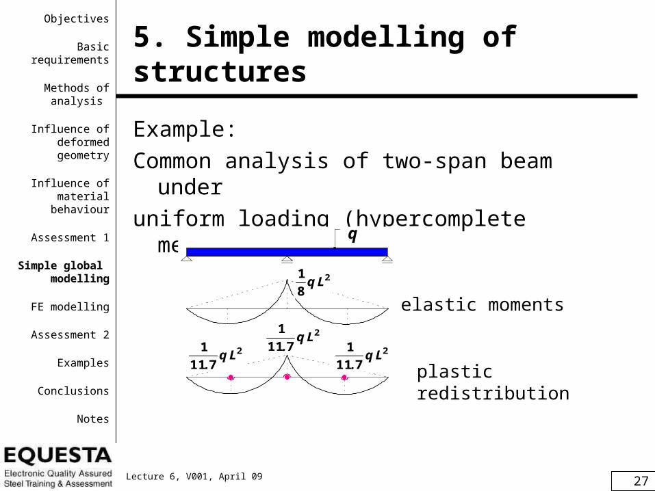
Example:
Common analysis of two-span beam under
uniform loading (hypercomplete mechanism):
q
2
8
1Lq
2
711
1Lq
.
elastic moments
plastic redistribution
2
711
1Lq
.2
711
1Lq
.
Objectives
Basic requirements
Methods of analysis
Influence of deformed geometry
Influence of material
behaviour
Assessment 1
Simple global modelling
FE modelling
Assessment 2
Examples
Conclusions
Notes

28Lecture 6, V001, April 09
6. FE modelling
Requirements for FEM are given in EN
1993-1-5, Annex C. Special care is due to:• the modelling of the structural component
and its boundary conditions;• the choice of software and documentation;• the use of imperfections;• the modelling of material properties;• the modelling of loads;• the modelling of limit state criteria;• the partial factors to be applied.
Objectives
Basic requirements
Methods of analysis
Influence of deformed geometry
Influence of material
behaviour
Assessment 1
Simple global modelling
FE modelling
Assessment 2
Examples
Conclusions
Notes

29Lecture 6, V001, April 09
6. FE modelling
Limit state criteria:
1. For structures susceptible to buckling:
Attainment of the maximum load.
2. For regions subjected to tensile stresses:
Attainment of a limiting value of the
principal membrane strain (5%).
Other criteria may be used, e.g. attainment of the
yielding criterion or limitation of the yielding zone.
Objectives
Basic requirements
Methods of analysis
Influence of deformed geometry
Influence of material
behaviour
Assessment 1
Simple global modelling
FE modelling
Assessment 2
Examples
Conclusions
Notes
30Lecture 6, V001, April 09
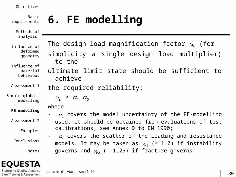
6. FE modelling
The design load magnification factor u (for
simplicity a single design load multiplier) to the
ultimate limit state should be sufficient to achieve
the required reliability:
u > 1 2
where
- 1 covers the model uncertainty of the FE-modelling
used. It should be obtained from evaluations of test calibrations, see Annex D to EN 1990;
- 2 covers the scatter of the loading and resistance
models. It may be taken as M1 (= 1.0) if instability governs and M2 (= 1.25) if fracture governs.
Objectives
Basic requirements
Methods of analysis
Influence of deformed geometry
Influence of material
behaviour
Assessment 1
Simple global modelling
FE modelling
Assessment 2
Examples
Conclusions
Notes

31Lecture 6, V001, April 09
Formative Assessment Question 2
• Describe common calculation models for braced building frame.
• Describe common calculation models for a truss.
• Describe common plastic models for continuous beams under various loadings.
• How ULS may be determined when using various FEM models (ranging from LA up to GMNIA)?
Objectives
Basic requirements
Methods of analysis
Influence of deformed geometry
Influence of material
behaviour
Assessment 1
Simple global modelling
FE modelling
Assessment 2
Examples
Conclusions
Notes
32Lecture 6, V001, April 09
7. Examples
Example 1: Two-bay braced frame
Example 2: Two-hinged arch
Example 3: Plate under uniform loading
Objectives
Basic requirements
Methods of analysis
Influence of deformed geometry
Influence of material
behaviour
Assessment 1
Simple global modelling
FE modelling
Assessment 2
Examples
Conclusions
Notes

33Lecture 6, V001, April 09
7.1 Example 1
Example 1:
Two-bay braced frame
Geometry and cross sections: composite floor beams: A= 9345 mm2, I = 127.4.106 mm4
6 000
HE
160
B
3 60
03
600
420
0
11 4
00
2L 90x8
2L 90x8
2L 110x10
HE
160
B
HE
160
B
6 000
Objectives
Basic requirements
Methods of analysis
Influence of deformed geometry
Influence of material
behaviour
Assessment 1
Simple global modelling
FE modelling
Assessment 2
Examples
Conclusions
Notes
The frames spacedat distance of 6 m,bracing each 12 m.

34Lecture 6, V001, April 09
7.1 Example 1
Loading [kN]
• vertical loading of columns; • winter loading due to this bracing;• global imperfections due to this bracing (from 2 cross frames): imp 1 = 21.6 = 3.2 kN; imp 2 = imp 3 = 21.5 = 3.0 kN.
VEd,1 VEd,2
HEd,2HEd,1
306.0 153.0
137.5 275.0
275.0137.5
30.8
56.0
62.0
imp 1
imp 2
imp 3
153.0
137.5
137.5
HEd,3
VEd,3
Objectives
Basic requirements
Methods of analysis
Influence of deformed geometry
Influence of material
behaviour
Assessment 1
Simple global modelling
FE modelling
Assessment 2
Examples
Conclusions
Notes

35Lecture 6, V001, April 09
7.1 Example 1
LA - model
used model:
inappropriatemodels:
unstable long critical lengths of diagonals
Objectives
Basic requirements
Methods of analysis
Influence of deformed geometry
Influence of material
behaviour
Assessment 1
Simple global modelling
FE modelling
Assessment 2
Examples
Conclusions
Notes

36Lecture 6, V001, April 09
7.1 Example 1
LA - internal forces(due to loading including global imperfections)
MEd [kNm] NEd [kN]
-0.46
-428-918-228-31
-0.79 -0.46
-217
Objectives
Basic requirements
Methods of analysis
Influence of deformed geometry
Influence of material
behaviour
Assessment 1
Simple global modelling
FE modelling
Assessment 2
Examples
Conclusions
Notes

37Lecture 6, V001, April 09
7.1 Example 1
LBA – critical modes
(loading including global imperfections)
6 first critical modes are shown for demonstration:
cr,1 = 5.51 cr,2 = 7.37 cr,3 = 8.30(central column) (bottom diagonal) (middle diagonal)
Objectives
Basic requirements
Methods of analysis
Influence of deformed geometry
Influence of material
behaviour
Assessment 1
Simple global modelling
FE modelling
Assessment 2
Examples
Conclusions
Notes

38Lecture 6, V001, April 09
LBA – critical modes
(loading including global imperfections)
7.1 Example 1
cr,4 = 11.75 cr,5 = 14.40 cr,6 = 16.95 (right column) (central column) (upper diagonal)
Note: The first sway mode is the 15th, where cr,15 = 144.1; Using approximate formula:
Objectives
Basic requirements
Methods of analysis
Influence of deformed geometry
Influence of material
behaviour
Assessment 1
Simple global modelling
FE modelling
Assessment 2
Examples
Conclusions
Notes
9192062
4200
01712
0162
EdH,Ed
Edcr .
..
.h
V
H

39Lecture 6, V001, April 09
• Notes for design:
- The frame is classified as second order frame
(cr,1 = 5.51 < 10). However, the buckling modes
are of non-sway character. The possibilities
mentioned for analysis (see 5.1) are discussed:
a) GNIA may generally be used, where unique imperfection for this frame e0 = 8.5 mm was determined in Lecture 5. Approximate global imperfections and imperfections of individual elements in accordance with Eurocode 3 or their equivalent transverse loadings may also be used. However, such analyses are generally demanding.
7.1 Example 1
Objectives
Basic requirements
Methods of analysis
Influence of deformed geometry
Influence of material
behaviour
Assessment 1
Simple global modelling
FE modelling
Assessment 2
Examples
Conclusions
Notes

40Lecture 6, V001, April 09
7.1 Example 1
Objectives
Basic requirements
Methods of analysis
Influence of deformed geometry
Influence of material
behaviour
Assessment 1
Simple global modelling
FE modelling
Assessment 2
Examples
Conclusions
NotesMEd [kNm] NEd [kN]
-0.77 -0.43 -0.44
-217 -918 -428-3
1 -228
b) GNA for global analysis of the structure with global imperfections is simple, provided non-linear
software is available. Resulting internal forces:
Compare differences between LA and GNA: here negligible.

41Lecture 6, V001, April 09
Member stability checks should be based on
buckling lengths equal to the system lengths.
Amplified LA is questioned in spite of cr,1 = 5.51
> 3 due to non-sway buckling character.
Member stability checks should also be based on
buckling lengths equal to the system lengths.
Details of the method are given for another example in
Module 4: Frame Stability.
7.1 Example 1
Objectives
Basic requirements
Methods of analysis
Influence of deformed geometry
Influence of material
behaviour
Assessment 1
Simple global modelling
FE modelling
Assessment 2
Examples
Conclusions
Notes

42Lecture 6, V001, April 09
c) LBA gives the first buckling mode which corresponds
to buckling of bottom central column, which may be
designed for internal forces from LA (imperfection
may be neglected) and following global slenderness
or global buckling length:
7.1 Example 1
Objectives
Basic requirements
Methods of analysis
Influence of deformed geometry
Influence of material
behaviour
Assessment 1
Simple global modelling
FE modelling
Assessment 2
Examples
Conclusions
Notes
50010918515
23554253
Edcr
y
cr
y ..N
fA
N
N
mm319510918515
109224102103
632
cr
2
cr
.
.
N
IEL

43Lecture 6, V001, April 09
The buckling mode is non-sway (see the picture)
and due to elastic constraint from upper parts of the
columns the Lcr < h = 4200 mm.
Note: Other members may be designed conservatively for the
same cr,1. Moments due to sway effects (here
negligible) should be increased approx. by 20%.
7.1 Example 1
Objectives
Basic requirements
Methods of analysis
Influence of deformed geometry
Influence of material
behaviour
Assessment 1
Simple global modelling
FE modelling
Assessment 2
Examples
Conclusions
Notes

44Lecture 6, V001, April 09
Summary concerning the three approaches:
• GNIA introducing all kind of imperfections (suitable for all cr) is demanding, usually not employed.
• GNA using global imperfections may be used, followed by member stability checks for system critical lengths. Simplified amplified LA may similarly be used for cr,1 ≥ 3 but is appropriate for predominantly sway buckling modes.
• LA followed by member stability checks using critical lengths from LBA should account for moments due to sway effects.
• Braced multi-storey frames are usually non-sway.
7.1 Example 1
Objectives
Basic requirements
Methods of analysis
Influence of deformed geometry
Influence of material
behaviour
Assessment 1
Simple global modelling
FE modelling
Assessment 2
Examples
Conclusions
Notes

45Lecture 6, V001, April 09
7.2 Example 2
Example 2:
Two-hinged arch (IPE 360, S355)
4 0 0 0 0
8000
1 ,8 0 k N /m + v la s tn í t íh a IP E
4 ,5 k N /m9 ,0 k N /m
4 0 0 0 0
8000
1 ,8 0 k N /m + v la s tn í t íh a IP E
4 ,5 k N /m9 ,0 k N /m
40 m
8 m
snow
permanentloading
+ weight of IPE
Objectives
Basic requirements
Methods of analysis
Influence of deformed geometry
Influence of material
behaviour
Assessment 1
Simple global modelling
FE modelling
Assessment 2
Examples
Conclusions
Notes

46Lecture 6, V001, April 09
7.2 Example 2
LA - internal forces:
14 1 ,2 10 6 ,2
22 6 ,0M [k N m ]N [k N ]
14 1 ,2 10 6 ,2
22 6 ,0M [k N m ]N [k N ]
Objectives
Basic requirements
Methods of analysis
Influence of deformed geometry
Influence of material
behaviour
Assessment 1
Simple global modelling
FE modelling
Assessment 2
Examples
Conclusions
Notes

47Lecture 6, V001, April 09
7.2 Example 2
LBA - critical loading:
(cr = 2.82)
When LA is used, the reduction coefficient y(a) = 0.22.
first critical mode
01210226822
1025813
3
,,N
N
N
N
Edcr
Rk
cr
Rk
Objectives
Basic requirements
Methods of analysis
Influence of deformed geometry
Influence of material
behaviour
Assessment 1
Simple global modelling
FE modelling
Assessment 2
Examples
Conclusions
Notes
e0
48Lecture 6, V001, April 09
7.2 Example 2
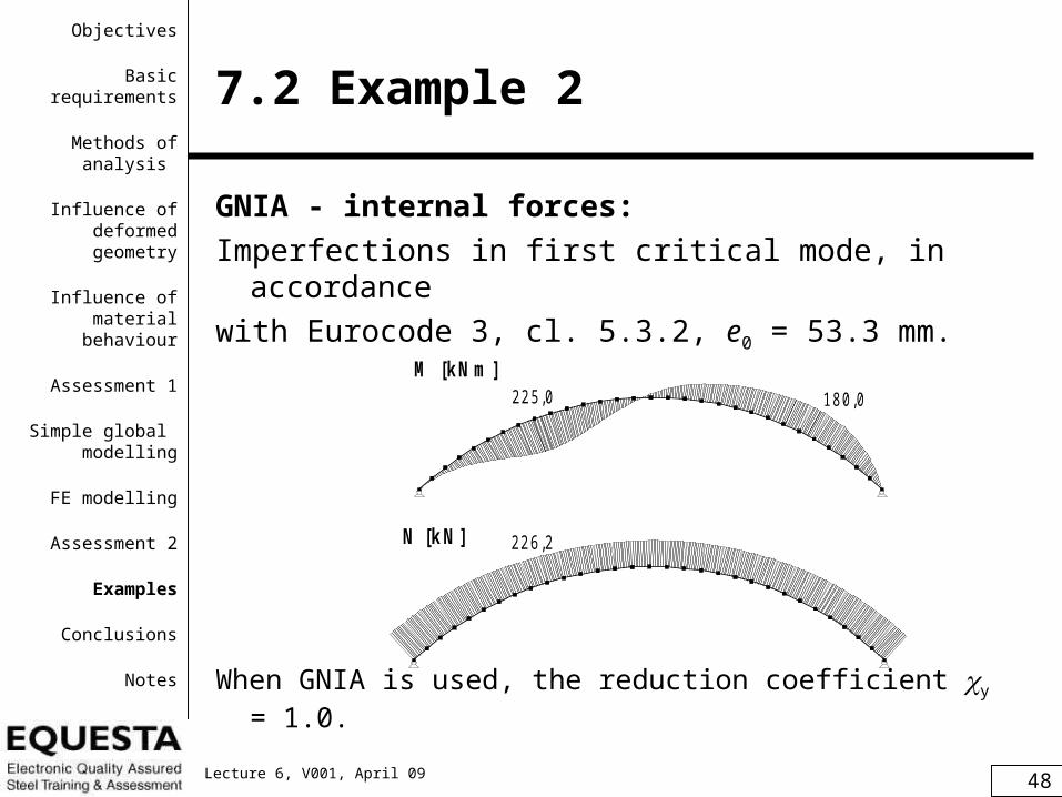
GNIA - internal forces:
Imperfections in first critical mode, in accordance
with Eurocode 3, cl. 5.3.2, e0 = 53.3 mm.
When GNIA is used, the reduction coefficient y = 1.0.
22 5 ,0 18 0 ,022 6 ,2M [k N m ] N [k N ]
22 5 ,0 18 0 ,022 6 ,2M [k N m ] N [k N ]
Objectives
Basic requirements
Methods of analysis
Influence of deformed geometry
Influence of material
behaviour
Assessment 1
Simple global modelling
FE modelling
Assessment 2
Examples
Conclusions
Notes

49Lecture 6, V001, April 09
7.2 Example 2
Summary of the comparison of LA and GNIA
for the arch:
• Using LA the reduction coefficient for compression y(a) = 0.22 shall be used in design.
• Using GNIA (geometrically non-linear analysis with imperfections) the maximum moment increased about 1.6 times, while reduction coefficient for compression is y = 1.0.
• Comparing resulting cross sections the GNIA is more economic.
Objectives
Basic requirements
Methods of analysis
Influence of deformed geometry
Influence of material
behaviour
Assessment 1
Simple global modelling
FE modelling
Assessment 2
Examples
Conclusions
Notes

50Lecture 6, V001, April 09
7.3 Example 3
Example 3:
Plate under uniform loading q (edges simply supported with zero membrane stresses)
Objectives
Basic requirements
Methods of analysis
Influence of deformed geometry
Influence of material
behaviour
Assessment 1
Simple global modelling
FE modelling
Assessment 2
Examples
Conclusions
Notes
51Lecture 6, V001, April 09
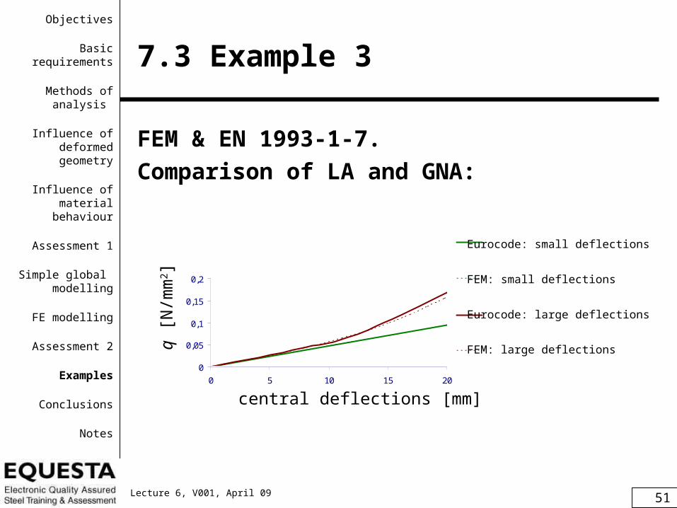
7.3 Example 3
FEM & EN 1993-1-7.
Comparison of LA and GNA:
Rovnoměrné zatížení(malé a velké průhyby, výsek)
0
0,05
0,1
0,15
0,2
0 5 10 15 20
průhyb [mm]
zatí
žen
í [N
/mm
2]
Eurokód: malé průhyby
MKP: malé průhyby
Eurokód: velké průhyby(okraje posuvné)
MKP: velké průhyby(okraje posuvné)
central deflections [mm]
q [N
/mm
2 ]
Eurocode: small deflections
FEM: small deflections
Eurocode: large deflections
FEM: large deflections
Objectives
Basic requirements
Methods of analysis
Influence of deformed geometry
Influence of material
behaviour
Assessment 1
Simple global modelling
FE modelling
Assessment 2
Examples
Conclusions
Notes

52Lecture 6, V001, April 09
7.3 Example 3
FEM & EN 1993-1-7.
Comparison of LA and GNA: Napětí v desce rovnoměrně zatížené(výsek do napětí 500 MPa)
0
0,05
0,1
0,15
0,2
-200 -100 0 100 200 300 400 500
napětí [MPa]
zatí
žen
í [N
/mm
2]
Eurokód:napětí - horní tlak,dolní tah (malé průhyby)
MKP: napětí - horní tlak,dolní tah (malé průhyby)
Eurokód: dolní napětí(velké průhyby,okrajeposuvné) Eurokód: horní napětí(velké průhyby,okrajeposuvné) MKP: dolní napětí (velképrůhyby,okraje posuvné)
MKP: horní napětí (velképrůhyby,okraje posuvné)
load
ing
[N/m
m2 ]
stresses at midspan [MPa]
Eurocode: top and bottomsmall deflections
FEM: top and bottomsmall deflections
Eurocode: bottomlarge deflections
Eurocode: toplarge deflections
FEM: bottomlarge deflections
FEM: toplarge deflections
Objectives
Basic requirements
Methods of analysis
Influence of deformed geometry
Influence of material
behaviour
Assessment 1
Simple global modelling
FE modelling
Assessment 2
Examples
Conclusions
Notes

53Lecture 6, V001, April 09
7.3 Example 3
Summary of the comparison of LA and GNA
for the thin plate in bending:
• Using GNA (large deflection theory of plates) the deflections and stresses for the same loading are lower than using LA (small deflection theory of plates).
• LA gives uneconomic solution.
Objectives
Basic requirements
Methods of analysis
Influence of deformed geometry
Influence of material
behaviour
Assessment 1
Simple global modelling
FE modelling
Assessment 2
Examples
Conclusions
Notes

54Lecture 6, V001, April 09
8. Conclusions
1) Appropriate models of analysis (from LA up to GMNIA) should be used in accordance with investigated limit state and expected results.
2) Geometrically nonlinear models are essential for structures changing significantly shape under loading (cables, cable nets, structures and members in buckling etc.).
3) Approximate LA may be used provided the influence of deflections and imperfections are adequately covered in both global and member analysis.
Objectives
Basic requirements
Methods of analysis
Influence of deformed geometry
Influence of material
behaviour
Assessment 1
Simple global modelling
FE modelling
Assessment 2
Examples
Conclusions
Notes

55Lecture 6, V001, April 09
8. Conclusions
4) Elastic analysis is always safe but usually uneconomical.
5) Materially nonlinear models may be used as far as special requirements on steel, cross sections and boundary conditions are met.
6) FEM (from LA up to GMNIA) requires special care and factored design loading should achieve at given limit state required reliability.
Objectives
Basic requirements
Methods of analysis
Influence of deformed geometry
Influence of material
behaviour
Assessment 1
Simple global modelling
FE modelling
Assessment 2
Examples
Conclusions
Notes

56Lecture 6, V001, April 09
Notes to Users of the Lecture
• This session is for modelling and analysis of structures and requires about 60 minutes lecturing and 60 minutes tutorial session.
• Within the lecturing, calculation models ranging from LA to GMNIA are described. Influence of deformed geometry and of material behaviour is shown with focus on multi-storey frames and floor elements. Analysis using FEM in general form and use of its results for design with harmony of Eurocodes is also presented.
• Further readings on the relevant documents from website of www.access-steel.com and relevant standards of national standard institutions are strongly recommended.
• Formative questions should be well answered before the summative questions completed within the tutorial session.
• Keywords for the lecture:
calculation model, linear analysis, non-linear analysis, elastic analysis, plastic analysis, bifurcation analysis, sway frame, frame stability, FE analysis.
Objectives
Basic requirements
Methods of analysis
Influence of deformed geometry
Influence of material
behaviour
Assessment 1
Simple global modelling
FE modelling
Assessment 2
Examples
Conclusions
Notes

57Lecture 6, V001, April 09
Notes for lecturers
• Subject: Modelling and analysis of structures.
• Lecture duration: 60 minutes plus 60 minutes tutorial.
• Keywords: calculation model, linear analysis, non-linear analysis, elastic analysis, plastic analysis, bifurcation analysis, sway frame, frame stability, FE analysis.
• Aspects to be discussed: types of analyses, requirements for use of various analyses, modelling of frames, trusses, beams.
• Within the lecturing, the modelling of multistorey frames incl. stability problems and GNA should be practised. Attention should also be paid to modelling of trusses and beams using LA and MNA.
• Further reading: relevant documents www.access-steel.com and relevant standards of national standard institutions are strongly recommended.
• Preparation for tutorial exercise: see examples within the lecture.
Objectives
Basic requirements
Methods of analysis
Influence of deformed geometry
Influence of material
behaviour
Assessment 1
Simple global modelling
FE modelling
Assessment 2
Examples
Conclusions
Notes