6 design parameters 4 6.1 glossary and definitions 4 6.2 ... · the above values are consistent...
TRANSCRIPT

Distribution Design Manual Part B, section 6, Page
This document is the property of Electricité du Laos. Unauthorised use is strictly forbidden. This is a controlled document and users are advised to verify that they have a current approved version.
1
6 DESIGN PARAMETERS 4 6.1 Glossary and Definitions 4 6.2 Standard Voltages and Frequency 5
6.2.1 Transmission 5 6.2.2 Subtransmission 6 6.2.3 MV Distribution 6 6.2.4 LV Distribution 7
6.3 Point of Supply 8 6.4 Customer Supply Voltages 9
6.4.1 Standard Medium Voltage supply 9 6.4.2 Standard Low Voltage supply 9
6.5 Distribution System Configurations 11 6.5.1 Three phase MV 11 6.5.2 SWER MV 12 6.5.3 Shieldwire earth return 12 6.5.4 Three phase and single phase LV 13 6.5.5 230-0-230v single phase LV 14
6.6 MV Network Electrical Characteristics 16 6.6.1 Connection 16 6.6.2 Rating 16 6.6.3 Switchgear 16 6.6.4 Spur fusing 17 6.6.5 MV arresters 17 6.6.6 Rod gaps 18 6.6.7 Transformer MV fuses. 18 6.6.8 Phasing sign 18
6.7 LV Network Electrical Characteristics 19 6.7.1 Rating 19 6.7.2 Fusing 19 6.7.3 LV Arresters 19
6.8 Earthing Systems 21 6.8.1 MV network 21 6.8.2 Safety Considerations in LV AC Systems 21 6.8.3 Characteristics of Systems 27 6.8.4 LV earthing policy 32 6.8.5 Construction requirements 32
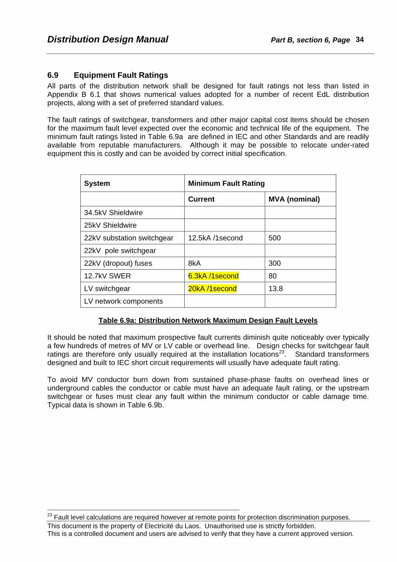
6.9 Equipment Fault Ratings 34 6.10 Transformer Vector Groups and technical characteristics 36 6.11 Network Electrical Design 40
6.11.1 Overhead lines impedances 40 6.11.2 Transformer regulation 40 6.11.3 Volt drop calculations 41 6.11.4 Volt drop allocation 44 6.11.5 Diversity 48 6.11.6 Estimation of maximum demand on consumer installations 49 6.11.7 Estimation of transformer maximum demand 51 6.11.8 Load Balance 52 6.11.9 Power factor 52
6.12 Environmental Data 57 6.12.1 Weather 57 6.12.2 Vegetation 58

Distribution Design Manual Part B, section 6, Page
This document is the property of Electricité du Laos. Unauthorised use is strictly forbidden. This is a controlled document and users are advised to verify that they have a current approved version.
2
6.12.3 Thunderstorms 58 6.12.4 Earthquakes 58 6.12.5 Cultural and scenic 59
6.13 Clearances 60 6.14 Overhead conductors 63
6.14.1 Conductor materials 63 6.14.2 Conductor temperature 65 6.14.3 Current rating 65 6.14.4 Fault rating 65 6.14.5 Conductor tensions 66 6.14.6 EdL Standard Conductors 68
6.15 Overhead Conductor Mechanical Loading 69 6.15.1 Sag and tension 69 6.15.2 Design wind loads 70 6.15.3 Conductor loading conditions 71
6.16 Poles 72 6.16.1 Concrete poles 72 6.16.2 Steel poles 73 6.16.3 Wooden poles 73
6.17 Crossarms 74 6.17.1 Concrete crossarms 75 6.17.2 Steel crossarms 75 6.17.3 Timber crossarms 75
6.18 Insulators 76 6.18.1 MV insulators 76 6.18.2 LV insulators 77
6.19 Conductor Hardware 78 6.19.1 Helical full tension joints 78 6.19.2 Helical dead-end fittings 78 6.19.3 Compression joints 78 6.19.4 Parallel groove connectors 79 6.19.5 Insulation piercing connectors 79
6.20 Other Hardware 81 6.21 Distribution Transformers 82
6.21.1 Transformer specification 82 6.21.2 Transformer selection 82
6.22 Transformer LV Cables 84 6.22.1 Derating factors 84 6.22.2 LV cable bending limits 84 6.22.3 Selection of LV cable size 85
6.23 Soils and Foundations 89 6.23.1 Classification 89 6.23.2 Backfill 90 6.23.3 Bearing pads 90
6.24 Guying 92 6.24.1 Guy design 92 6.24.2 Guying materials 92
6.25 LV Aerial Bundled Conductor 95 6.25.1 Characteristics 95 6.25.2 LVABC hardware 96 6.25.3 Selection of cable system 97 6.25.4 Design Loadings 98

Distribution Design Manual Part B, section 6, Page
This document is the property of Electricité du Laos. Unauthorised use is strictly forbidden. This is a controlled document and users are advised to verify that they have a current approved version.
3
6.26 Electrical Protection 100 6.26.1 Purpose 100 6.26.2 MV equipment 100 6.26.3 LV equipment 101 6.26.4 Discrimination 101 6.26.5 Protection relays 101 6.26.6 MV Fuses 101 6.26.7 LV fuses and circuit breakers 102
6.27 Metering 108 6.27.1 Installation 108 6.27.2 Meter ratings 109 6.27.3 Meter Multipliers 110 6.27.4 Guidelines as to Selection of 3-phase Metering Arrangements 110 6.27.5 LV meter selection 111 6.27.6 MV meter selection 112 6.27.7 Meter test blocks 113 6.27.8 Voltage supply fuses 113 6.27.9 Standard metering wiring connections 114 6.27.10 Tariff Meters 114
6.28 Meter Testing 115 6.28.1 Single-phase meters 115 6.28.2 Three-phase whole current meters 116 6.28.3 Three-phase 4-wire CT operated meters 117 6.28.4 Three-phase 3-wire CT (and VT) operated 118 6.28.5 Meter Adjustment 118 6.28.6 Meters tested at consumer request 118 6.28.7 Field Testing of Revenue Meters 119 6.28.8 Field Testing of Statistical Meters 121

Distribution Design Manual Part B, section 6, Page
This document is the property of Electricité du Laos. Unauthorised use is strictly forbidden. This is a controlled document and users are advised to verify that they have a current approved version.
4
6 DESIGN PARAMETERS
6.1 Glossary and Definitions AAC All-Aluminium Conductor ABS Air break switch with load breaking capability ABI Air break isolator without load breaking capability ACSR Aluminium Conductor Steel Reinforced AS Australian Standard BS British Standard HV High voltage, >69kV Ib Basic current of a direct connected kWh meter at which the performance is
defined (sometimes called rated current) Imax Rated maximum of a kWh meter In Rated current of a CT operated kWh meter at which the performance is
defined IPC Insulation Piercing Connector LV Low voltage, < 1kV LVABC Low voltage aerial bundled conductor LV Distributor A low voltage circuit for transfer of energy from a transformer to where the
consumer service line is connected, usually a multi-branch radial MV Medium voltage, 1kV < U <69kV MEN Multiple Earthed Neutral PoS Point of Supply SC/AC Steel conductor, aluminium clad Service line The conductors between the LV circuit (distributor) in the road/street to the
entry point on an electrical installation used exclusively for that installation. Service main The conductors internal to an electrical installation between the entry point
and the main switchboard or meter location. SWER Single Wire Earth Return TCOL, OLTC Tap Change on Load VRR Voltage Regulating Relay XLPE Crosslinked Polyethylene

Distribution Design Manual Part B, section 6, Page
This document is the property of Electricité du Laos. Unauthorised use is strictly forbidden. This is a controlled document and users are advised to verify that they have a current approved version.
5
6.2 Standard Voltages and Frequency EdL has adopted a rationalised range of transmission and distribution voltages aligned to British, European and IEC practice. These include 115kV(110kV), 22kV, and 380/220v. 12.7kV SWER1 is in use and is a logical derivative from 22kV as the same insulators and fuses as on the 3-wire 22kV system can be utilised. 12.7kV is the phase to ground voltage on a three-phase 22kV system. The use of 25kV and 34.5kV for shieldwire based distribution is an unfortunate departure towards American standard voltages which has required the purchase and stocking of different transformers, insulators, MV fuses and related hardware. The standard frequency is 50Hz.
6.2.1 Transmission EdL has adopted 115kV as its standard transmission voltage. The system is three-phase, solidly grounded. All transmission lines are constructed on steel towers and most are single circuit. Transmission and major substation voltage ratings and insulation levels are based on: Nominal voltage 115kV Highest (operating) system voltage approx. 120kV Highest system voltage for equipment (Um) 123kV Power frequency withstand 230kV Rated impulse withstand 550kV Some older substations have 110kV nominal rated equipment with insulation levels as above. The above values are consistent with Um = 123kV from Table 2 range 1 of IEC 60071-1. Some segments of the transmission network utilise shieldwire(s) insulated from ground to afford a local distribution supply. Because of the particular insulation co-ordination requirements of the shieldwire system and the chosen distribution voltages, the next highest level of insulation ratings from IEC60071-1 have been adopted. The relevant ratings are: Nominal voltage 115kV Highest (operating) system voltage approx. 120kV Highest system voltage for equipment (Um) 145kV Power frequency withstand 275kV Rated impulse withstand 650kV Both 115kV and 110kV (nominal voltage) power transformers have on-load or off-load tapping facilities with a sufficient range to be operated at 115kV. However it should be noted that the tap change equipment is operated near one extremity of the design range. Voltage transformers at major supply substations have 110volt or 100volt secondary windings some of which are configured 110/√3 or 100/√3volt.
1 Single Wire Earth Return method of distribution.

Distribution Design Manual Part B, section 6, Page
This document is the property of Electricité du Laos. Unauthorised use is strictly forbidden. This is a controlled document and users are advised to verify that they have a current approved version.
6
6.2.2 Subtransmission Subtransmission systems are used for the bulk distribution of blocks of power from major supply substations (115kV) to smaller zone substations. Characteristics of subtransmission networks include:
• No direct supply to consumers, • Wider range of design operating voltage2, • On-load tapchange equipment at the receiving end transformers (eg. 33/22kV), • Duplicate supplies to minimise outages.
At present EdL does not use any subtransmission systems. Should these be adopted in the future candidate voltages are likely to be either 33kV or 66kV.
6.2.3 MV Distribution The standard EdL MV distribution voltage is 22kV. The system is three-phase, solidly grounded. The related design voltages and insulation levels are: Nominal voltage 22kV Highest (operating) system voltage approx. 23kV Highest system voltage for equipment (Um) 24kV Power frequency withstand 50kV Rated impulse withstand 125kV The above values are consistent with Um = 24kV from Table 2 range 1 of IEC60071-1. In some areas adjacent to the border with Vietnam supply is imported and locally distributed at nominal 35kV. This system is three-phase, solidly grounded. The related design voltages and insulation levels are: Nominal voltage 35kV Highest (operating) system voltage 38kV Highest system voltage for equipment (Um) 38kV Power frequency withstand 70kV Rated impulse withstand 150kV The above values are consistent with Um = 38kV from Annex A table A.1 of IEC60071-1. The 12.7kV SWER system is single-phase solidly earthed and has design voltages and insulation levels: Nominal voltage 22kV (12.7kV phase to ground) Highest (operating) system voltage approx. 23kV (13.3kV phase to ground) Highest system voltage for equipment (Um) 24kV (14kV phase to ground) Power frequency withstand 50kV Rated impulse withstand 125kV The 34.5kV twin shieldwire earth return system is 2-wire three-phase with one phase of the originating three phase system solidly earthed and has design voltages and insulation levels3:
2 Typically +5% to –10%. 3 Insulation level values as recommended by Prof. F Iliceto in appendix B2, PTD Project, Electrowatt Engineering, February 1997. The corresponding values from IEC60071-1 Table 2 for Um = 52kV are 95kV and 250kV.

Distribution Design Manual Part B, section 6, Page
This document is the property of Electricité du Laos. Unauthorised use is strictly forbidden. This is a controlled document and users are advised to verify that they have a current approved version.
7
Terminal Equipment Distribution Equipment Nominal voltage 34.5kV 34.5kV Highest (operating) system voltage approx. 36kV approx. 36kV Highest system voltage for equipment (Um) 60kV 52kV Power frequency withstand 95kV 82.5kV Rated impulse withstand 250kV 200kV The 25kV single shieldwire earth return system is single-phase solidly earthed and has design voltages and insulation levels4: Terminal Equipment Distribution Equipment Nominal voltage 25kV 25kV Highest (operating) system voltage approx. 27.5kV approx. 27.5kV Highest system voltage for equipment (Um) 48kV 48kV Power frequency withstand 82.5kV 82.5kV (70) Rated impulse withstand 200kV 200kV (170)
6.2.4 LV Distribution The standard LV distribution voltages are 380/220volt three-phase 4-wire, 220volt single-phase 3-wire and 220volt single-phase 2-wire. The system is most commonly operated with the neutral ungrounded. Some areas have a solidly grounded neutral. The insulation level is 0.6/1kV.
4 Insulation level values as recommended by Prof. F Iliceto in “Electric Power Distribution from the Insulated Shieldwire of Nam Ngum – Luang Prabang 115kV Transmission Line”, July 1992, edited by Electrowatt Engineering. The corresponding values from IEC60071-1 for Um = 36kV are 70kV and 170kV.

Distribution Design Manual Part B, section 6, Page
This document is the property of Electricité du Laos. Unauthorised use is strictly forbidden. This is a controlled document and users are advised to verify that they have a current approved version.
8
6.3 Point of Supply The point of supply (PoS) for electricity consumers is the connection point between the distribution network (owned and operated by EdL) and the consumer installation. The PoS defines where cost and technical responsibilities transfer. This is commonly the terminals or connection point between the external service line and the internal service main on an installation. Where the service line is continuous without joints or terminals the PoS may be considered as at the main switchboard or the location of the energy meters.

Distribution Design Manual Part B, section 6, Page
This document is the property of Electricité du Laos. Unauthorised use is strictly forbidden. This is a controlled document and users are advised to verify that they have a current approved version.
9
6.4 Customer Supply Voltages Standard customer supply voltages are derived from the three-phase or single-phase MV and LV systems. Voltages used for direct supply to consumers are:
22kV three-phase 3-wire, 380/220volt three-phase 4-wire, 220volt single-phase 2-wire.
On three-phase supplies the voltage vectors are displaced nominally 120o. The 220volt 2-wire voltages are derived from the three-phase and single-phase LV networks. In the case of 220volt single-phase 3-wire distribution 220volt connections are taken between one of the outer conductors and the centre or (neutral) conductor. Although a hybrid 440volt “two-phase” 220-0-220volt supply with the phases displaced 180o is possible, EdL does not at present use this connection. At the PoS it is commercially important that the technical characteristics of the electricity supply be defined between EdL (the supplier) and the consumer (the purchaser). In this way the obligations and rights of each party are established. A standard supply voltage enables consumers to purchase electrical appliances and equipment that will operate safely and efficiently and to design their own internal wiring systems to deliver a satisfactory electricity supply to the final point of use. Conversely EdL need a set of rules that can be used in the design and operation of the distribution network to ensure that the defined standard voltage is provided to consumers. To date EdL has not formally defined standard supply voltages and associated allowable limits. Even if the recommended standard supply voltages cannot be legally adopted for some time, the proposed values should be used for all design and new construction with immediate effect. This will ensure that all future construction is to a satisfactory technical basis. EdL should adopt a policy to review the existing LV network to identify areas where excessive voltage drop occurs and institute a programme to bring the system up to standard over a period of say 10years. This work could be incorporated into a Loss Reduction programme. The following standard supply voltages measured at the PoS are recommended for adoption:
6.4.1 Standard Medium Voltage supply • Frequency 50Hz ± 0.75Hz (ie. 49.25Hz to 50.75Hz) apart from momentary fluctuations. • Three-phase 3-wire solidly grounded system. • 22,000volts between phases for 2-wire single supply, • 22,000volts between phases for three-phase supply. • A tolerance of ± 5% on nominal voltage apart from momentary fluctuations.
6.4.2 Standard Low Voltage supply • Frequency 50Hz ± 0.75Hz (ie. 49.25Hz to 50.75Hz) apart from momentary fluctuations. • Three phase 4-wire Multiple Earthed Neutral (MEN) system. • 220volt between phase and neutral for single phase supply, • 380volt between phases for two phase supply, • 380volt between phases for three-phase supply. • A tolerance of ± 6% on nominal voltage apart from momentary fluctuations.
IEC 60038 recommends 400/230volt ±10% as the standard LV voltage, and proposes a transition from 380/220volt in stages to the new value. Commencing with the present 380/220v ± 6% recommended for formal adoption by EdL, the transition steps should be 380/220v +10% -6%,

Distribution Design Manual Part B, section 6, Page
This document is the property of Electricité du Laos. Unauthorised use is strictly forbidden. This is a controlled document and users are advised to verify that they have a current approved version.
10
followed by 400/230v +6% -10%, and later 400/230v ±10%. It should be noted that 380/220v +10% -6% and 400/230v +6% -10% are essentially the same in terms of the extreme values (see Table 6.4), and can be achieved with existing 400/230volt transformers.
Nominal phase – neutral voltage Declared Voltage
Maximum Minimum 380/220v ± 6% 233.2 206.8
380/220v +10% -6% 242.0 206.8
400/230v +6% -10% 243.8 207.0
400/230v ±10% 253.0 207.0
Table 6.4: Voltage Limits for Different Declared Voltages To enable this step-by-step transition it is most important that the minus 6% variation (-6%) on 380/220v be adopted forthwith and followed rigorously. Design procedures should be consistent with a transition to the new standard voltage 400/230v +6% -10%. Adoption of ±10% voltage variation will in due course permit an increase in the MV feeder allowable voltage drop. A move to 400/230v ±10% will require the use of 415/240volt transformers, and will take much longer to become effective. Accordingly this particular change is only noted for future action.

Distribution Design Manual Part B, section 6, Page
This document is the property of Electricité du Laos. Unauthorised use is strictly forbidden. This is a controlled document and users are advised to verify that they have a current approved version.
11
6.5 Distribution System Configurations
6.5.1 Three phase MV The most widely used systems of MV distribution are three-phase. EdL has standardised on the 3-wire solidly earthed configuration. The characteristics of this configuration are a three-conductor main distribution network supplied from a star connected transformer(s) at the major substation with a solidly earthed neutral. Three-phase MV/LV distribution transformers are connected to all three phases directly on the main line or on 3-wire spur lines. The system also allows the use of transformers with a 2-wire primary (commonly called single phase) that are connected across any two of the three main conductors directly on the main line or on 2-wire or 3-wire spurs.
transformer(s)Three phase
transformer(s) transformer(s)Three phase Single phase
Figure 6.5.1: MV, Three-phase, three-wire system A three-phase backbone feeder may commonly have a rating of up to about 8MVA usually limited by permissible volt drop. Three phase lines are invariably installed where there are motors of more than 5kW individual rating. Spur lines are of more limited capacity, say 500kVA, and if of 2-wire construction can only supply single-phase loads. Any electrical imbalance due to the presence of two wire spurs can be reduced by the connection of different spurs to different pairs of conductors on the three phase line to achieve equal current loading in each phase conductor along the main three phase feeder. In this system phase to phase faults are only limited by the conductor and source impedances and large fault currents can flow. This simplifies detection, but requires protection devices (fuses or circuit breakers) of adequate interrupting capacity. Phase to ground faults also include the impedance of the earth path and are commonly of smaller magnitude than phase-phase (overcurrent) faults. To reduce the magnitude of earth fault currents and consequential damage, the neutral at the source of supply can be resistance or impedance earthed, or the supply can be grounded via an earthing transformer. Direct (or solid) earthing is simple and effective and is entirely suitable for the present stage of development of the EdL distribution network. Alternative earthing methods can be adopted in the future without major disruption. While some countries (eg. USA, Japan) use a three-phase 4-wire system with extensive use of phase-neutral single-phase transformers, the configuration could result in higher overall costs if used by EdL. The existing 3-wire solidly earthed configuration is entirely satisfactory for EdL, and should be retained. Any attempts to introduce alternative systems should be strongly opposed because of additional operational complexity and a wider range of required materials.

Distribution Design Manual Part B, section 6, Page
This document is the property of Electricité du Laos. Unauthorised use is strictly forbidden. This is a controlled document and users are advised to verify that they have a current approved version.
12
6.5.2 SWER MV For long lightly loaded spur lines a single conductor form of reticulation can be adopted where the normal return path is through the general mass of earth. In appropriate circumstances this system can provide a very low cost method of distribution for small loads. To avoid the earth return currents returning to the major substation star point and thereby reducing the sensitivity to genuine earth faults on the 3-wire network, it is usual to install a double-wound isolating transformer at the commencement of the single wire spur line. This also restricts the region of earth currents to the area served by the individual SWER spur.
SWER distribution transformers
Isolating Transformer
transformer(s)Three phase
SWER
Figure 6.5.2: MV, SWER system
Only single-phase loads can be supplied and each SWER spur is usually limited by the maximum permissible earth return current. It is inherent in this system that normal load current, not only fault current, flows in the earth and which can cause interference to metallic telecommunications circuits as well as other metallic overhead, surface and buried services. By careful design any such problems can be minimised. Of critical importance with any earth return system is the design of the connections to earth as these must be of low resistance and be configured to avoid hazardous step and touch potentials. There are numerous variations on the supply and earthing arrangements for earth return systems. A useful reference on the subject is “High Voltage Earth Return Distribution for Rural Areas”. 5 Economy of construction can be achieved by the use of the same insulators, MV fuses, and surge arresters, as for 3-wire MV distribution. On a three-phase 22kV system the voltage to earth which determines the insulation requirements is 22kV/√3 or 12.7kV. 12.7kV is chosen as the phase to ground operating voltage for EdL SWER distribution to permit the use of common materials. Identical clearances to ground and structure parts as for the 22kV network are applicable. SWER distribution transformers are of necessity different from 2-wire single-phase transformers because the applied MV voltage is respectively 12.7kV and 22kV. On SWER transformers the earthed end of the MV winding must be brought out on a bushing (of nominal insulation level) so that the earth connection can be made electrically independent of other metal work.
6.5.3 Shieldwire earth return In rural areas where load density is low the cost of main supply substations often makes grid sourced electricity supply uneconomic. Places traversed by transmission lines but remote from main supply substations can be given a distribution supply from an insulated shieldwire used as a 5 Issued by the Electricity Authority of New South Wales, Australia, revised edition 1978

Distribution Design Manual Part B, section 6, Page
This document is the property of Electricité du Laos. Unauthorised use is strictly forbidden. This is a controlled document and users are advised to verify that they have a current approved version.
13
SWER circuit on the transmission line. This innovative technique has been utilised by EdL based on pioneering work in Ghana by Professor Dr. F. Iliceto.6 The technical literature describes both theoretical and practical aspects of this system.7,8 Between Nam Ngum and Luang Prabang the single shieldwire is energised at 25kV from inputs at Vang Vieng and Luang Prabang. The 25kV supply is obtained from 22/25kV single-phase SWER isolating transformers. Spur lines are taken off the shieldwire at intervals to supply 25kV single-phase SWER distribution transformers up to 75kVA rating. For correct operation particular attention is required to the provision of a low impedance MV earth return path. This is achieved by multiple earthing of a continuous MV overhead earth conductor erected along the route of each MV spur. The design details of this scheme are outlined in the project design report.9 The single transmission shieldwire conductor limits the scheme to single phase distribution supply. For the Power Transmission and Distribution Project (PTD) twin shieldwires are provided on the 115kV transmission lines. The shieldwires lines will be insulated and supplied at 34.5kV from a tertiary delta winding on the 115kV transformer at the main supply substations, with one phase terminal of the delta earthed. Conventional delta/star 3-phase transformers operated with one MV phase terminal earthed can be supplied from this 2-wire system. In this way normal 3-phase 4-wire LV supply can be provided. The scheme can also provide single-phase (230v, and 230-0-230v) supply from single phase 2-wire and SWER transformers.10 In both single and twin shieldwire schemes the reactance of the earth return path is corrected by the installation of capacitors. Although unusual, the shieldwire method of distribution supply is economic and has been shown to be technically viable. EdL have experienced some operational problems including failures of transformers (attributed to the manufacturer's non-compliance with specifications), incorrect installation of tension insulators, and incorrect protective relay settings. The MV voltages (25kV and 34.5kV) in use on the shieldwire are not IEC or EdL standards and require purpose built transformers and non-standard line hardware. Because of the onerous environment and the unusual phase-earth voltages, equipment has been specified with non-standard insulation (BIL) levels (refer section 6.2). To avoid expensive design and testing costs manufacturers usually supply equipment to the next highest IEC standard insulation ratings.11
6.5.4 Three phase and single phase LV The three phase LV system used by EdL is 4-wire (three phase and neutral) 380/220volt with the voltage vectors displaced nominally 120o. Three phase transformers are vector group Dyn11. Users should be aware that if the MV phases are connected in reverse sequence to a Dyn11 transformer it becomes vector group Dy1, and the emergency paralleling of LV supplies is not possible. 6 “Lightly Loaded Long Transmission Lines. Guidelines Prepared at the Request of the World bank” F. Iliceto. Washington 7 “New Concepts on MV Distribution from Insulated Shieldwires of HV Lines”, Iliceto, et al, IEEE Transactions on Power Delivery, Vol4, No 44, October 1989. 8 “ A New Method for the Analysis of Power Distribution Schemes at MV Using the Insulated Shieldwires of HV Lines. Operation Results in Ghana”. Cinteri, Iliceto and Dokyi, IEEE/CIGRE Africon ’92 Conference, September 1992. 9 “Nam Ngum – Luang Prabang Transmission Project”, Electrowatt Engineering Services, 1992. 10 Power Transmission and Distribution Project TA Study, Electrowatt Engineering Services, Appendix B2, Final Report, February 1997. 11 For the 34.5kV system, equipment rated 52/95/250kV from table 2 of IEC71-1 is the next standard rating. For the 25kV system, equipment rated 36/70/170kV from table 2 of IEC71-1 is the next standard rating.

Distribution Design Manual Part B, section 6, Page
This document is the property of Electricité du Laos. Unauthorised use is strictly forbidden. This is a controlled document and users are advised to verify that they have a current approved version.
14
LV Distributors are 4-wire, 3 wire (two phase and neutral), and 2-wire (phase and neutral). All main LV Distributors should be constructed 4 wire, for ease of system operation, flexibility of development and load growth, and to simplify of load balancing. Minor spurs servicing up to six consumers may be 3-wire provided voltage drop limits are not exceeded. 2-wire LV spurs should not be constructed. In the past the LV neutrals have often been unearthed but all future construction shall have a continuous multiple earthed neutral. Service connections to consumers are usually three phase 380/220v (4-wire) or single-phase 220v (2-wire, phase - neutral). See Figure 6.4.4. The standard supply voltages are 380/220volt ±6% and 220volt ±6%. Two-phase (3-wire) supply is also possible but is not presently used.
4-Wireb
Three phaseservice service
Two phaseservice
Single phase
c
380/220 VaN
Figure 6.5.4: Consumer Supplies from 4-wire 380/220volt system
6.5.5 230-0-230v single phase LV The LV supply derived from single-phase (mono) transformers is a 3-wire system obtained by the series connection of the two 230volt secondary windings. From the 3-wire LV distribution 220volt connections are taken between one of the outer conductors and the centre or (neutral) conductor. Care must be taken to distribute the load evenly between the two “phase” conductors to ensure near equal loading on each of the secondary windings, and to minimise volt drop along the middle “neutral” conductor. See Figure 6.4.5. A 2-wire system may be taken from the same transformers with the two secondary windings connected in parallel. Although a hybrid 440volt “two-phase” 220-0-220volt supply with the phases displaced 180o is possible, EdL does not at present use this connection.

Distribution Design Manual Part B, section 6, Page
This document is the property of Electricité du Laos. Unauthorised use is strictly forbidden. This is a controlled document and users are advised to verify that they have a current approved version.
15
230 V
230 V
S in g le -p h ase 3 -w ire L V C o n n ectio n
2 30V
S in g le -p h ase 2 -w ire L V C o n n ectio n
22kV
f
22kVf
f
n
a
a2
a1n
Figure 6.5.5: Supply from Single-phase Transformer
Distribution Design Manual Part B, section 6, Page
This document is the property of Electricité du Laos. Unauthorised use is strictly forbidden. This is a controlled document and users are advised to verify that they have a current approved version.
16
6.6 MV Network Electrical Characteristics
6.6.1 Connection The primary function of the MV network is the delivery of energy to distribution transformers. The MV Distribution network comprises 22kV feeders originating at major substations and express feeder switching stations. Each feeder is controlled by a circuit breaker at the point of origin. The network is operated radially with limited capability in town areas for interconnection between feeders. Distribution transformers which may be overhead (pole mounted) or ground level, are supplied directly from the MV feeder, or from MV spur lines. Distribution transformers shall be individually protected on the MV side by fuses. Distribution transformers may be owned by EdL or privately owned by a consumer.
6.6.2 Rating MV feeders shall be sized to meet the voltage drop criteria (refer separate section), have adequate current rating for the expected maximum loads, and conductors shall have sufficient fault rating to avoid burn down in the event of a phase to phase fault.
6.6.3 Switchgear For economic reasons most pole mounted MV switchgear is of the simple manually operated air break type. It is not capable of interrupting fault current, and may have only limited fault making rating. Pole mounted load break switches (LBS) may be either totally enclosed SF6 gas or vacuum type, or air break type. Common ratings are 400amp and 630amp with a fault rating of 12.5kA (nominally 500MVA at 22kV). Pole mounted disconnecting switches12 (DS) are commonly air break pattern with flicker type arc horns that afford a load interrupting capability of not more than 10amp. All new air break switches shall be fitted with flicker arc horns. Plain contact disconnecting switches should not be used to interrupt load current, but are suitable for paralleling feeders or off-load (de-energised) operation. Within the interconnected network load break switches need only be installed at every second switch position on a ring as a parallel can be broken on the intermediate DS and the remaining load interrupted on the LBS. Three-phase gang operated load break (LBS) and non-load break disconnecting (DS) switches should be installed at network junction points to permit the redistribution of feeder loading, and after every fifth transformer or every 5km whichever is the lesser. Standard dropout fuses shall not be used for this purpose, as the contacts are not rated for switching load current.13 Fuses or other single phase switching devices must not be used on interconnecting or paralleling circuits as their operation will usually activate residually connected earth fault relays at the supply substations. Automatic Reclosers and Sectionalisers should be installed on long overhead feeders prone to fault interruptions. In selecting sites for the location of these switchgear items it should be remembered that their prime purpose is to maintain or restore supply to customers upstream of the
12 Also known as air break isolating switches (ABI) 13 Dropout fuses fitted with load break heads, link break dropout fuses, or portable loadbreak devices are suitable for load interruption.

Distribution Design Manual Part B, section 6, Page
This document is the property of Electricité du Laos. Unauthorised use is strictly forbidden. This is a controlled document and users are advised to verify that they have a current approved version.
17
fault location. Accordingly best results are usually achieved when the switchgear is installed immediately beyond significant load centres. On underground cabled MV networks ground mounted switchgear is usually installed. For feeder switching load break fault make switchgear rated 400amp or 630amp with a fault rating of 12.5kA (nominally 500MVA at 22kV) is required. Switchgear is oil filled, SF6 gas or vacuum type. Switchgear, often as part of a ringmain unit, is installed at every transformer position to simplify the isolation of faulted cable sections.
6.6.4 Spur fusing Overhead MV spur lines shall be protected by dropout fuses where the connected transformer capacity does not exceed 200kVA. Where the connected transformer capacity exceeds 200kVA, the spur should be connected hard-on, although a ready means of isolation (eg. DS) should be provided if the spur line is more than 5km length or is difficult to patrol. Spur fuses may be omitted where the spur supplies only one transformer, is not more than 300metre in length, and is clearly visible for its entire length from the takeoff point. Spur fuses must be current rated to discriminate with the upstream protective devices.
6.6.5 MV arresters MV lightning (surge) arresters shall be fitted:
• at every overhead distribution transformer, • at every cable connection to an overhead line, and • at 5km intervals along the feeder unless there is a suitably equipped transformer within
that distance. Because of the very high frequencies often associated with lightning strokes, arresters shall be installed as close as practicable to the transformer or cable termination. On overhead transformer structures the highest level of protection is afforded when the arresters are installed at the MV bushings. In the event of an arrester discharging due to a lightning strike the resulting power arc if it develops will cause the dropout fuses to operate and isolate the installation. It is EdL practice to install the arresters at or immediately before the dropout fuses. This is generally considered not to afford adequate protection for the transformer windings. When installed upstream of the dropout fuse an arrester discharge may cause a feeder interruption, but this avoids numerous “blown” fuses from lightning storms and overall speeds up the restoration of supply. Arresters are not required on underground cabled networks except at cable riser pole connections to the overhead network. Surge arresters shall comply with IEC60099. Metal-oxide arresters without gaps offer superior performance to earlier types. The following characteristics are appropriate for use by EdL on 22kV MV feeders.
Arrester rated voltage 21kV Maximum Continuous Overvoltage (MCOV) 18kV Duty Cycle Current Rating 10kA
To assist with fault location and save outage times, arresters should incorporate an automatic disconnection device to operate in the event of an arrester failure. Additional information can be obtained from IEC60099-5.
Distribution Design Manual Part B, section 6, Page
This document is the property of Electricité du Laos. Unauthorised use is strictly forbidden. This is a controlled document and users are advised to verify that they have a current approved version.
18
6.6.6 Rod gaps Air insulated rod gaps are sometimes used as a simple form of overvoltage protection. They suffer from a number of disadvantages including:
• Variable flashover voltage according to atmospheric conditions, • Result in a power arc that must be interrupted by another device eg. fuse or circuit breaker. • Can be shorted out by birds, snakes or debris that often requires the use of two or more
series gaps, • Can get out of adjustment and thereby not function as designed.
EdL has adopted modern surge arresters that offer superior performance, so rod gaps should only be used in particular circumstances where discharge will not cause other operational problems.
6.6.7 Transformer MV fuses Every distribution transformer shall be protected on the primary side with suitably rated dropout fuses. The insulation level of dropout fuses shall be consistent with other parts of the MV network, but the fault rating is usually limited to 8kA. MV fuses for transformer protection are required to carry normal load and overload without deterioration of the operating characteristics, and also clear both low current and high current faults. The time-current characteristic of the fuse link is carefully controlled to enable correct discrimination with other fuses and devices. A distribution fuse-cutout is defined in IEC 60282-2 as a dropout fuse comprising a fuse base, a fuse carrier lined with arc-quenching material, and a fuse-link having a flexible tail, and a small diameter arc-quenching tube surrounding the fuse element. In some designs the arc quenching tube may be moisture tight and contain a powder surrounding the fusible element. At low fault levels a thermal joint in the element will melt from the generated heat and release the preload tension from the dropout flipper spring. At high current faults the heater wire melts to give a different clearing time. The products resulting from rapid heating and expansion of the powder and/or the tube material expel and extinguish the arc. Arc extinction is usually effected within the arc quenching tube of the disposable fuse-link that leaves the tube of the fuse carrier undamaged.
6.6.8 The phasing sign of 22Kv distribution line. Phase 1 ⇒ A (red) on road sign. Phase 2 ⇒ B (yellow) Phase 3 ⇒ C (blue) White back ground colour The phasing sign shall be show:
- At the start and the end point of feeder. - At the start and the end point of branch. - At every overhead distribution transformer and at the disconnecting switch.

Distribution Design Manual Part B, section 6, Page
This document is the property of Electricité du Laos. Unauthorised use is strictly forbidden. This is a controlled document and users are advised to verify that they have a current approved version.
19
6.7 LV Network Electrical Characteristics The purpose of the LV network is to distribute energy away from distribution transformers in order to give supply to consumers. The LV network shall be constructed and operated as a Multiple Earthed neutral (MEN) system. The neutral conductor on every LV distributor shall have a cross-section not less than the phase conductors.
6.7.1 Rating The conductor cross-section of LV distributors shall be selected to meet the voltage drop criteria (refer separate section), and to have adequate current rating for the expected maximum loads. LV distributors should be constructed with the same rated conductors throughout their length. To assist with phase balancing and to minimise volt drop each LV three-phase distributor should be of 4-wire construction over its entire length. Similarly for 3-wire reticulation from single-phase transformers, construction should be 3-wire over the entire length. The construction of tapered LV Distributors14, or reducing the number of phase conductors, should be avoided, as the savings are often small. Such practices restrict flexibility for subsequent load growth, ease of balancing, and the installation of additional transformers.
6.7.2 Fusing The LV network shall be fused or protected by a circuit breaker on the LV side of every distribution transformer. LV distributors shall be individually fused radial spur lines, unless the transformer is rated 50kVA and smaller in which case a single set of LV side fuses shall be used at the transformer. The purpose of the fuses is to protect the transformer from damage resulting from phase to phase or phase to neutral/earth faults on LV distributors. The fuses provide a measure of overload protection for the transformer. Because distribution transformer impedances seldom exceed 6%, the MV side fuses adequately protect against internal transformer faults (both MV and LV), but not overload.
6.7.3 LV Arresters One set of LV surge arresters shall be installed on the LV conductors at every distribution transformer and connected to the LV neutral. Additional arresters should be installed at the ends of all LV distributors at a location where there is a LV neutral earth. The arresters must be connected between each phase conductor and neutral15. An extra arrester shall be connected to any streetlighting phase conductor at the arrester location. LV surge arresters shall be metal oxide type and shall comply with IEC60099. Arresters that clamp directly to the LV conductors are simple to install. The following arrester characteristics are appropriate for use by EdL on LV distributors.
Arrester rated voltage 500v Maximum Continuous Overvoltage (MCOV) 420v Rated discharge current 2.5kA Duty Cycle Current Rating 10kA
14 A tapered LV distributor uses progressively smaller conductors with distance from the transformer as loading decreases. 15 The LV neutral should be earthed at every LV arrester location except for the arresters at a distribution transformer. The transformer LV neutral earth is at the first LV pole away from the transformer.
Distribution Design Manual Part B, section 6, Page
This document is the property of Electricité du Laos. Unauthorised use is strictly forbidden. This is a controlled document and users are advised to verify that they have a current approved version.
20
Additional information can be obtained from IEC60099-5. To assist with fault location and save outage times, arresters should incorporate an automatic disconnection device to operate in the event of an arrester failure.

Distribution Design Manual Part B, section 6, Page
This document is the property of Electricité du Laos. Unauthorised use is strictly forbidden. This is a controlled document and users are advised to verify that they have a current approved version.
21
6.8 Earthing Systems The EdL transmission system is solidly earthed. While design considerations for the transmission network are beyond the scope of this Manual, users should be aware of the nature of the transmission and major substation earthing systems and their relationship with the distribution network particularly under fault conditions. An essential consideration in the design and rating of an earthing system is the maximum current that can flow through any particular part of the earthing system for a specific time. The current is limited by: • System upstream impedance (source impedance) • Fault impedance • Resistance of the local earthing connection • The number of parallel paths • Mutual coupling effects.
6.8.1 MV network The MV network shall be solidly earthed. As all distribution transformers on the MV network have a three-phase delta connected or two-phase primary winding, the only operational point of earthing is at the major substation.16 The neutral point of the star connected secondary (22kV) winding of the main supply transformers at major substations shall be directly connected to the substation earth grid. Typically the resistance of the earth grid will be less than 0.5 ohm. All associated metalwork not normally alive shall be bonded to the same earth system. At major substations MV lightning arresters may be directly connected to the same earth grid. Where cables are used on MV feeders at major substations the cable sheaths and armouring must be solidly connected to the substation earth grid to form a MV MEN. Where MV cables are used on parts of a feeder separated from the major substation by a section of overhead line, the cable sheaths and armouring must be solidly connected to the local MV earth grids. Care must be taken on polymeric cables that the cable sheaths and armouring are adequately rated or alternative measures taken (e.g. provision of a separate earth wire along the route of the cable. On MV feeders all exposed metalwork not normally alive shall be directly earthed to a locally established earth system fitted with a test link. The maximum resistance of the local earth grid shall be 30ohm. Locations include distribution transformer substations, switching stations, ABI’s, LBS’s, MV capacitor installations, voltage regulators, etc. Concrete poles, concrete crossarms, steel crossarms and similar items on other poles do not require direct earthing. MV lightning arresters shall be earthed by an independent connection without a test link but may utilise the same earth grid.
6.8.2 Safety Considerations in LV AC Systems
6.8.2.1 Risks Electrical networks are insulated from earth and exposed metallic parts to provide protection for persons, and to enhance continuity of supply. To provide safety to people and animals, and minimise the risk of damage to buildings by fire, it is necessary to detect and isolate insulation faults. Earthing the supply system neutral will ensure 16 Earthing of equipment with star connected primary windings (e.g. 3-phase voltage booster transformers) shall be subject to special consideration.

Distribution Design Manual Part B, section 6, Page
This document is the property of Electricité du Laos. Unauthorised use is strictly forbidden. This is a controlled document and users are advised to verify that they have a current approved version.
22
that an insulation breakdown results in a fault current large enough to operate protective devices (usually fuses or circuit breakers).17 An insulation fault presents risks for human life, for the preservation of property, and the continuity of power supply. The most important of these is avoidance of electric shock to persons. A person subjected to an electric voltage may suffer:
• discomfort, • muscular contraction, • burns, • cardiac arrest,
according to the duration and current passing through the body. There are a number of factors that affect the severity of an electric shock including at LV, impedance of the body (usually impedance of the skin), the path taken through the body, and wet or dry external conditions. IEC60479-1 defines a safety voltage UL that is the maximum acceptable contact voltage that can be sustained for at least 5 seconds. The time current effects are illustrated in Figure 6.7.1 that is derived from IEC60479-1.
Zone 1: Felt but no reaction Zone 2: Considerable discomfort Zone 3: Muscular contractions Zone 4: Risk of cardiac arrest (greater risk with increased exposure)
Figure 6.8.2.1: Time/current zones of effects of AC currents (15Hz to 100Hz) 17 This subject is more fully discussed in reference texts. A useful summary can be found in Cahier Techniques No’s 172 and 173, Merlin Gerin, September 1995. Additional reading, more particularly about the MEN system, is included in the course training notes prepared by Worley for EdL Training in New Zealand, May 2000.

Distribution Design Manual Part B, section 6, Page
This document is the property of Electricité du Laos. Unauthorised use is strictly forbidden. This is a controlled document and users are advised to verify that they have a current approved version.
23
6.8.2.2 Voltages IEC60364-4-41 defines a safety voltage UL = 50volt ac for distribution circuits that is the maximum acceptable contact voltage that can be sustained for not more than 5 seconds.18 If there is a risk that any contact voltage UC > UL the exposure time must be limited by the use of protection devices. IEC60364-4-442 sets out the requirements for the protection of LV installations against faults between MV systems and earth at a distribution substation. To avoid excessive potential rise on the LV system when a MV fault occurs, the neutral conductor must be earthed independently of the MV earth at the transformer substation, unless the MV earth is less than 1ohm or the MV fault is cleared very rapidly. As these cannot generally be assured, an independent LV earth shall be installed. The maximum clearance times for MV faults to ensure no hazard is shown in Figure 6.8.2.2 from IEC60364-4-442.
Figure 6.8.2.2: Maximum Permissible Duration of Fault Voltage F and Touch Voltage T Due
to an Earth Fault
6.8.2.3 Contacts The hazards to persons arise from direct contact or indirect contact. Direct contact is where there is an accidental contact by a person with normally live conductors (phase or neutral). Protection measures include:
• use of insulation, • locating live parts out of reach, • use of enclosures or barriers.
The risk of injury can be reduced by the installation of Residual Current Devices (RCD’s). 18 Much shorter times (typically 0.4 second) are specified for final circuits in buildings.

Distribution Design Manual Part B, section 6, Page
This document is the property of Electricité du Laos. Unauthorised use is strictly forbidden. This is a controlled document and users are advised to verify that they have a current approved version.
24
Indirect contact is where there is a contact by a person with the frame of an appliance or other metal work that has become accidentally energised. The accidental energising is the result of an insulation breakdown. A fault current may flow between frame and earth, causing a fault voltage that is dangerous if it exceeds UL. Supply should be automatically disconnected if the value and duration of the touch voltages of IEC60479-1 are exceeded. Methods of installation for control of the hazard are detailed in IEC60364.
6.8.2.4 Standard LV Distribution Systems Before discussing how hazards can be controlled, a review of standard systems and earthing arrangements is helpful. IEC60364 (clause 312) classifies LV distribution systems by arrangement of live conductors, and earthing arrangements. There are a number of standard arrangements of live conductors at LV. Of these, EdL use:
Single-phase 2-wire Single-phase 3-wire Three-phase 4-wire.
IEC60364 recognises a number of methods for LV system earthing including: TN, in which there is one point directly earthed, and all exposed metal is connected to that point by protective conductors. Three types of TN are listed:
TN-S system has separate neutral and protective earth (PE) conductors. TN-C system in which the neutral and PE are combined throughout (PEN). TN-C-S system which combines the TN-S and TN-C systems with the proviso that the TN-C part must be upstream.
TT, in which there is one point directly earthed, and all exposed metal is connected to earth electrodes electrically independent of the earth electrode(s) of the supply. IT, in which all live parts are isolated from earth (or one point connected to earth through an impedance), and all exposed metal of the consumer installation is earthed independently. The codes have the following meanings:
First letter – Relationship of the power system to earth: T = direct connection to one point of earth; I = all live parts isolated from earth, or one point connected to earth through an impedance.
Second letter – Relationship of the exposed conductive parts of the installation to earth: T = direct electrical connection of exposed conductive parts to earth, independently of the earthing of any point of the power system; N = direct electrical connection of exposed conductive parts to the earthed point of the power system (normally the neutral).
Subsequent letter(s) (if any) – Arrangement of neutral and protective conductors: S = protective function provided by a conductor separate from the neutral. C = neutral and protective functions combined in a single conductor (PEN conductor).
These schemes are illustrated in Figures 6.8.2.4a to 6.8.2.4f that are derived from IEC60364.

Distribution Design Manual Part B, section 6, Page
This document is the property of Electricité du Laos. Unauthorised use is strictly forbidden. This is a controlled document and users are advised to verify that they have a current approved version.
25
Figure 6.8.2.4a: Symbols According to IEC617-11(1983)
Figure 6.8.2.4b: TN-C System
Figure 6.8.2.4c: TN-S System

Distribution Design Manual Part B, section 6, Page
This document is the property of Electricité du Laos. Unauthorised use is strictly forbidden. This is a controlled document and users are advised to verify that they have a current approved version.
26
Figure 6.8.2.4d: TN-C-S System
Figure 6.8.2.4e: TT System
Figure 6.8.2.4f: IT System
Distribution Design Manual Part B, section 6, Page
This document is the property of Electricité du Laos. Unauthorised use is strictly forbidden. This is a controlled document and users are advised to verify that they have a current approved version.
27
6.8.3 Characteristics of Systems In the event of an insulation failure in a LV network the protective device(s) must operate before the touch voltage reaches an unsafe level. The IEC Standard makes it quite clear that regardless of what system is used, the lowest possible fault loop impedance is essential. It should be noted that all systems require direct earthing either of the neutral, conductive parts on installations, or both. In any network phase-earth or phase-neutral-earth fault currents must return to the neutral point of the source transformer even if the neutral conductor is solidly earthed and/or interconnected to other transformer neutrals. In the TN system and its derivatives the earth fault loop comprises conductive elements so that any high earth resistances do not enter into the loop path. Simple overcurrent protection (fuse or circuit breaker) is suitable because of the relatively low loop resistance. Fuses provide a low-cost, reliable, and safe method of protection to persons. Fault voltages are inherently below 100volt and often less than 65volt. The performance of TN systems can be improved by the use of a separate protective conductor (PE) such as in the TN-S system, or a combined protective conductor (PEN) as in the TN-C system. In a TN-C system where the neutral is bonded to earth any phase-earth fault becomes a phase-neutral fault with faster clearance times because of the lower loop impedance. In the TN-C-S system a protective earth conductor is provided in installations downstream of a PEN on the distribution network. The performance of any TN network can be enhanced by the provision of multiple earth connections along and at the ends of the distribution neutral. This is the Protective Multiple Earth (PME) system widely used in the UK. This configuration gives a degree of safety and reliability for installations downstream of a broken neutral. The multiple earth connections lower the loop impedance by allowing some fault current flow through the general mass of earth. A multiple earth system (MEN) is a TN-C-S system with the addition of a direct earth connection at the consumer installation. This configuration further enhances the safety and performance of the network. Although the MEN system is not specifically recognised by IEC, it has been in use in New Zealand for over 75 years and Australia for 40 years. It is mandatory in these countries and is widely used in Malaysia, India and elsewhere. In the TT system the local installation earth electrode is electrically independent of the earth connection at the source of supply (the distribution transformer neutral terminal)19. When a phase-earth fault occurs at LV the fault voltage can rise to hazardous levels of the order 150 - 220volt. If the TT system is used in distribution networks, the only satisfactory protection is by Residual Current Devices (RCD) because of the high loop impedances. The IT system limits earth fault current by not having an earth connection at the source of supply (isolated neutral) or by the insertion of an impedance between neutral and earth. Conductive parts in consumer installations are required to be earthed. In IT a “first” fault to earth does not create a hazard and supply may continue while the defect is repaired. Should a second fault occur before the first is repaired, the case is similar to TN. The system may have applications in special purpose buildings (eg. hospitals), but in general is not suitable for distribution networks and is no longer commonly used. 19 The TT system is commonly used in transmission networks where low impedance installation earth connections (eg. substations) are economic and can be adequately maintained.

Distribution Design Manual Part B, section 6, Page
This document is the property of Electricité du Laos. Unauthorised use is strictly forbidden. This is a controlled document and users are advised to verify that they have a current approved version.
28
6.8.3.1 Advantages of TN system The TN system is the safest as phase-earth fault voltages are inherently lower than any of the other standard connections. Protection by fuses and circuit breakers is simple, effective and low-cost. Unless the first fault is monitored in IT and repairs are completed promptly this configuration is not safer than TN. TT is not suitable for distribution networks. This connection requires the general use of RCD’s with associated higher cost.
6.8.3.2 EdL Practice Previous EdL practice has been to operate the LV neutral unearthed. Consumer installations do not generally have protective conductors or a local earth electrode. Although this configuration may at first have the appearance of an IT system it does not comply with the IEC rules, because of the absence of a local protective earth conductor and earth electrode. In a standard IT system the return path for earth fault current is formed by the capacitive coupling of the energised conductors which is typically of high impedance and so the fault voltage is low. A first fault to earth of either a neutral or phase conductor causes no significant fault current to flow and is thereby safe from shock. This feature enhances continuity of supply without significant hazard. The occurrence of a second fault to earth from a different circuit conductor is a short circuit through earth with a significant fault voltage that may be hazardous. To gain the benefits of the IT system it is necessary to monitor the insulation of the live conductors at the supply point for a first fault and arrange for repairs before a second (and hazardous) fault occurs. In this way continuity of service is enhanced. EdL does not effectively monitor the supply at most transformers, so the possible technical and safety benefits are not utilised. Because insulation is not monitored and there is in general no knowledge of the first fault, the LV system operated by EdL is no more safe against shock voltages than a solidly earthed system. The occurrence of a second fault on an isolated neutral gives rise to the same electrical configuration as a first fault on a solidly earthed system. In all systems there is a continuing risk of insulation damage to installation wiring, appliances, and EdL owned equipment. In an unearthed system with a phase-to-earth fault on one phase, the voltage to earth of the “healthy” phases can rise to the phase-phase voltage by displacement of the neutral. See Figure 6.7.9. Insulation designed for phase-neutral voltage will be subject to up to √3 times that value. Whilst that may not be damaging for very short periods, sustained periods of excessive voltage will eventually lead to insulation failure in consumer installations and appliances. This is the most likely cause for the high failure rate of voltage coils on kWh meters experienced by EdL. On the existing EdL distribution network these excessive voltages may exist for long periods of time.
6.8.3.3 Earthed neutral system Where the neutral is effectively earthed any phase-to-earth fault is a phase-to-neutral fault and is a short circuit that will immediately cause operation of the protective devices. Any excessive voltages from neutral displacement will therefore be only of short duration.
Distribution Design Manual Part B, section 6, Page
This document is the property of Electricité du Laos. Unauthorised use is strictly forbidden. This is a controlled document and users are advised to verify that they have a current approved version.
29
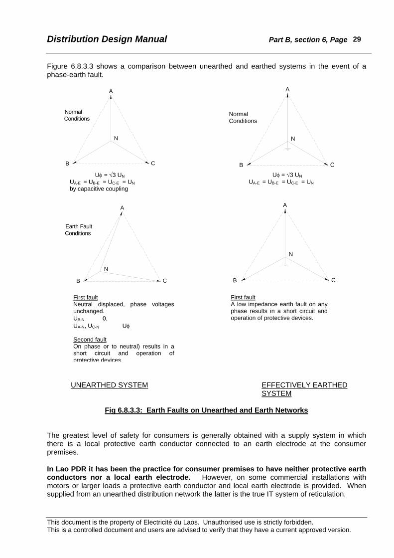
Figure 6.8.3.3 shows a comparison between unearthed and earthed systems in the event of a phase-earth fault.
UNEARTHED SYSTEM EFFECTIVELY EARTHED
SYSTEM
Fig 6.8.3.3: Earth Faults on Unearthed and Earth Networks
The greatest level of safety for consumers is generally obtained with a supply system in which there is a local protective earth conductor connected to an earth electrode at the consumer premises. In Lao PDR it has been the practice for consumer premises to have neither protective earth conductors nor a local earth electrode. However, on some commercial installations with motors or larger loads a protective earth conductor and local earth electrode is provided. When supplied from an unearthed distribution network the latter is the true IT system of reticulation.
Uφ = √3 UN UA-E = UB-E = UC-E = UN by capacitive coupling
First fault Neutral displaced, phase voltages unchanged. UB-N 0, UA-N, UC-N Uφ Second fault On phase or to neutral) results in a short circuit and operation of protective devices.
Uφ = √3 UN UA-E = UB-E = UC-E = UN
First fault A low impedance earth fault on any phase results in a short circuit and operation of protective devices.
Earth FaultConditions
B
A
N
C
A
B
N
C
A
B
N
C
A
Normal Conditions
B
N
C
Normal Conditions

Distribution Design Manual Part B, section 6, Page
This document is the property of Electricité du Laos. Unauthorised use is strictly forbidden. This is a controlled document and users are advised to verify that they have a current approved version.
30
Evidence from the past indicates that EdL is unable to monitor the occurrence of a first fault on an isolated neutral system even when facilities are provided. A method of LV distribution should be adopted which provides an adequate level of safety without technical risk to insulation or equipment. This can best be achieved by operating the LV distribution network with the neutral solidly earthed.
6.8.3.4 Multiple earthing Where the LV neutral is earthed near to the transformer, consideration must be given to a broken neutral conductor between the earth point and the consumer installation. If the LV distributor neutral is broken (or disconnected) the configuration becomes similar to the existing EdL system. If a phase-neutral fault occurs beyond the broken neutral a hazardous neutral to earth voltage will exist at all consumer installations beyond the broken neutral. On poly-phase installations insulation will be subjected to up to phase-phase voltage (√3 x Uo) with the consequent risk of insulation breakdown or damage. This risk can be significantly reduced if the neutral is earthed at the remote end and at regular intervals along its length. The multiple earth connections will usually afford a sufficiently low fault loop impedance to ensure operation of the LV protection at the transformer. The multiple earth connections have the additional benefit of reducing the fault voltage. This is the Protective Multiple Earth system used in the UK, and may be regarded as an enhanced TN-C system. On the MEN system the feature of multiple earthing is extended to an earth electrode at every consumer installation.
6.8.3.5 Consumer installation wiring and appliances Most domestic wiring installations in Lao PDR do not include protective earth (PE) wiring or a local earth electrode. Figure A of Appendix B6.19 shows a typical wiring arrangement for a single-phase domestic supply. Single-phase supply circuits are controlled by multi-pole circuit breakers with all conductors including the neutral protected and switched. Earth leakage circuit breakers (RCD’s) are widely used. On three-phase supply circuits it is customary for only the active conductors to be switched. Most socket outlets and appliance plugs in use in Lao PDR are non-polarised, two-pin, flat or round. Installation wiring methods do not always differentiate between phase and neutral. The insertion of an appliance plug is a random choice as to how the phase or neutral of the appliance becomes connected. A separate protective conductor can safely connect exposed metalwork within an installation to the neutral provided this is by fixed wiring. Exposed metalwork on portable appliances or other plug-in devices cannot be safely connected to the appliance neutral unless polarised plugs are used (and fixed wiring differentiates between phase and neutral conductors). The solution is to adopt appliance plugs that incorporate an additional pin for a protective conductor that independently connects the appliance frame to the neutral at the switchboard. On an installation with an unearthed neutral, if there is an insulation failure within the installation wiring or in an appliance there will be no hazard or supply interruption if there is no other pre-existing earth fault on the LV network. If there is already a phase-earth fault, the second fault will give rise to a hazardous voltage to earth with consequent danger to persons if the body of a person becomes part of the current path. Protective devices may not necessarily operate.
Distribution Design Manual Part B, section 6, Page
This document is the property of Electricité du Laos. Unauthorised use is strictly forbidden. This is a controlled document and users are advised to verify that they have a current approved version.
31
On an installation with an earthed neutral, if there is an insulation failure within the installation wiring or in an appliance, or anywhere on the LV network, the upstream protective devices will operate to isolate the fault and remove any hazard to persons. This configuration is shown in Figure B of Appendix B6.19 that is based on PEA Thailand practice. Where PE cables are installed and three-pin polarised plugs are used, any exposed metalwork can be earthed (by bonding). Safety is thereby significantly enhanced:
• Where the neutral is unearthed this becomes a compliant IT system • Where the neutral is single or multiple earthed, this is a TN-C-S MEN system. The wiring
arrangement for a single-phase MEN supply is shown in Figure C of Appendix B6.19.
6.8.3.6 Recommendation EdL should immediately adopt a LV system that incorporates a solidly earthed LV neutral. Where the distribution neutral is deliberately earthed the neutral conductor in a normal Lao PDR consumer installation is required to serve the dual purpose of neutral and protective earth. This is similar to the TN-C system except that no protective earth conductor is used within the installation20. This modified TN-C system could be introduced without the need for retrospective alteration to existing consumer wiring installations. Premises with a protective earth conductor and local earth electrode could then be configured as TN-C-S. On these installations it will be necessary to use only three-pin polarised socket outlets or double insulation if the full potential safety benefits are to be achieved. Both TN-C and TN-C-S systems are recognised in IEC60364. Materials and appliances designed to operate on these systems are readily available, and will give more satisfactory service than at present where sustained overvoltages may damage insulation. It is recommended that EdL adopt a technical policy that provides direct earthing of the LV neutral at: • the distribution transformer. • the end of every LV spur. • every third or fourth pole along the LV distribution line. This arrangement is an enhanced TN-C system. Suitably wired consumer installations can be connected in an enhanced TN-C-S MEN configuration. The present system of construction commonly used in Lao PDR which has an unearthed LV distribution neutral and no protective earth connections at consumer premises does not comply with any IEC or other recognised system. At present there are significant safety hazards to people and technical risks to equipment and appliances. In proposing an alternative arrangement it is important to: • Enhance safety, • Improve technical performance, • Comply with international Standards, • Minimise costs to EdL, • Minimise (and preferably avoid)costs to consumers on existing installations, • Ensure compatibility during changeover. The recommended procedure meets all of these criteria.
20 The TT and IT systems are not recommended as these mandatory require a local PEN and earth electrode, both of which are absent on most electrical installations in Lao PDR.

Distribution Design Manual Part B, section 6, Page
This document is the property of Electricité du Laos. Unauthorised use is strictly forbidden. This is a controlled document and users are advised to verify that they have a current approved version.
32
6.8.4 LV earthing policy The LV system shall be solidly earthed with a multiple earthed neutral, and where practicable the neutral shall be interconnected to adjacent LV networks. The overall resistance of the LV to remote earth shall not exceed 10ohm. The LV neutral point of distribution transformers shall be solidly connected to the LV distributor neutral conductor(s) and shall be directly connected to earth. The LV earth connections shall be independent of the MV earth system. The neutral conductor at the end of each LV distributor shall be earthed. Where practicable (such as where LV Distributors from adjacent transformers meet on the same pole), the neutral conductors from other transformers shall be interconnected. To ensure satisfactory operation of the LV network additional neutral earth connections shall be installed at every third or fourth pole (ie. at approximately 200m spacing) along each distributor. The neutral earth connections adjacent to the transformer shall each be fitted with a test link and shall each have a resistance not greater than 20ohm. Other LV earth connections should not exceed 40ohm and do not require test links.21 The use of multiple earth connections on the LV neutral ensures a low overall resistance and a good level of security should any one connection be damaged or fail.
6.8.5 Construction requirements The overall resistance of the LV distribution neutral shall be less than 10ohm. Where the recommended practices are followed the overall value will usually be less than about 3ohm. At every distribution transformer two LV earth grids shall be installed, one each at the first LV pole away from the transformer on two different distributors. This is necessary to ensure satisfactory separation from the MV earth grid at the transformer. Each grid shall be directly connected to the LV neutral. The earth lead to each of these earth grids shall be fitted with a test link located on the pole immediately above the polyethylene pipe and arranged to isolate the system neutral from the earth grid for testing. The test link shall be insulated or positioned so that it does not make electrical contact with the pole when it is opened. Each of these earth grids must have a measured resistance of not greater than 20 ohm. The provision of two separate earth grids provides security against damage to one of them and allows for routine testing. Sometimes it is not possible to install two LV earth grids on separate poles away from the transformer. In such cases one of the LV earth grids may be installed adjacent to the transformer pole provided it is separated by not less than 5m from any part of the MV earth grid, and the buried leads to the LV grid are electrically independent (eg. PVC covered conductor installed in polyethylene pipe). All LV earth connections on the distribution network shall be constructed with not less than 25mm2 copper conductor. All leads from the neutral conductor on the pole to the first earth rod the conductor shall be PVC covered. Beyond the first earth rod bare 25mm2 (or larger) copper
21 The combination of two 20ohm (max.) connections and of two 40ohm (max.) connections in parallel will give an overall resistance not exceeding 6.6ohm. A lower test value on any one earth connection, and the presence of other connections will result in a decrease in the overall resistance for the LV neutral.

Distribution Design Manual Part B, section 6, Page
This document is the property of Electricité du Laos. Unauthorised use is strictly forbidden. This is a controlled document and users are advised to verify that they have a current approved version.
33
conductor should be used. Copper conductor for earthing may be hard drawn or soft drawn.22 For mechanical protection, the earth lead between 2.5m above ground to 400mm below ground shall be installed inside a 20mm diameter polyethylene pipe. The polyethylene pipe and conductor shall be secured to the pole by stainless steel banding at intervals of not less than 750mm. All buried earth conductors shall be not less than 450mm below the ground surface. All earth rods shall be copper clad steel (or hot dip galvanised), not less than 2000 x 12mm diameter, and each fitted with a purpose-designed clamp suitable for up to three 25mm2 copper conductors. Earth rods shall be driven so that the top is not less than 450mm below ground surface. The LV earth grids adjacent to the transformer shall comprise not less than three standard earth rods spaced 3m or more in a triangular pattern around the LV pole. Where site conditions make this impractical the earth grid shall comprise not less than three standard earth rods spaced 2m or more installed in a straight line underneath the line of the overhead LV distributor. If additional earthing is required to achieve the 20ohm test in either case, the earth grid shall be extended in a radial pattern with bare 25mm2 (or larger) copper conductor and rods at not less than 2m spacing. Earth connections along the LV distributor and at the ends of the distributor shall comprise a single earth stake solidly connected to the neutral conductor with 25mm2 copper PVC covered conductor. No test link is required. Where LV distributors from adjacent transformers meet the neutral shall be interconnected and earthed. Table 6.8 summarises EdL network earthing arrangements
Location of Earth Connections Network Earthing
System Neutral Earth Typical Value Other Earths Typical
Value
Transmission Solidly Earthed at one location
Generation station. Major substation.
0.5ohm 0.5ohm
Structure steelwork. Transmission towers.
0.5ohm 10ohm
MV Solidly Earthed at one location
Major substation. 0.5ohm Structure steelwork. Steelwork at
distribution subs.
0.5ohm 30ohm
LV Solidly Earthed MEN Distribution sub. 2@
20ohm Along LV neutral. Ends of LV neutral
40ohm 40ohm
Table 6.8.5: EdL Network Earthing Arrangements
22 Second hand copper conductor dismantled from overhead lines is often suitable for earthing provided at least 90% of the strands are undamaged.
Distribution Design Manual Part B, section 6, Page
This document is the property of Electricité du Laos. Unauthorised use is strictly forbidden. This is a controlled document and users are advised to verify that they have a current approved version.
34
6.9 Equipment Fault Ratings All parts of the distribution network shall be designed for fault ratings not less than listed in Appendix B 6.1 that shows numerical values adopted for a number of recent EdL distribution projects, along with a set of preferred standard values. The fault ratings of switchgear, transformers and other major capital cost items should be chosen for the maximum fault level expected over the economic and technical life of the equipment. The minimum fault ratings listed in Table 6.9a are defined in IEC and other Standards and are readily available from reputable manufacturers. Although it may be possible to relocate under-rated equipment this is costly and can be avoided by correct initial specification.
System Minimum Fault Rating
Current MVA (nominal)
34.5kV Shieldwire
25kV Shieldwire
22kV substation switchgear 12.5kA /1second 500
22kV pole switchgear
22kV (dropout) fuses 8kA 300
12.7kV SWER 6.3kA /1second 80
LV switchgear 20kA /1second 13.8
LV network components
Table 6.9a: Distribution Network Maximum Design Fault Levels It should be noted that maximum prospective fault currents diminish quite noticeably over typically a few hundreds of metres of MV or LV cable or overhead line. Design checks for switchgear fault ratings are therefore only usually required at the installation locations23. Standard transformers designed and built to IEC short circuit requirements will usually have adequate fault rating. To avoid MV conductor burn down from sustained phase-phase faults on overhead lines or underground cables the conductor or cable must have an adequate fault rating, or the upstream switchgear or fuses must clear any fault within the minimum conductor or cable damage time. Typical data is shown in Table 6.9b.
23 Fault level calculations are required however at remote points for protection discrimination purposes.

Distribution Design Manual Part B, section 6, Page
This document is the property of Electricité du Laos. Unauthorised use is strictly forbidden. This is a controlled document and users are advised to verify that they have a current approved version.
35
Short Time Rating (Amp) Conductor or Cable
1.0 second 3.0 second Squirrel ACSR 2110 1220
Weasel ACSR 3180 1840
Mink ACSR 6360 3670
Leopard ACSR 13240 7640
Coyote ACSR 13220 7630
Wolf ACSR 15810 9130
240/40 ACSR
Mosquito AAC (bare and PVC) 3720 2150
Ant AAC (bare and PVC) 5340 3080
Fly AAC (bare and PVC) 6420 3710
Bluebottle AAC (bare and PVC) 7440 4290
4x70 LVABC
3x150.70LVABC
Table 6.9b: Conductor Short Time Ratings The clearance time of fuses is a function of the type and current rating of the fuse links. As an example a standard NEMA 22kV 10amp class K fuse link has a 1.0 second current rating of approximately 40amp. Reference should be made to manufacturer's data. See Appendix B 6.10. In general small conductors can be adequately protected from burn down by the use of fuses. Where fuses are not installed the conductor cross-section must be selected to be sufficient for the prospective fault current and the upstream relay and switchgear settings. The 3-second rating for conductor should be used for co-ordination to allow for limited cooling during autoreclose operations and general service ageing. The clearance time of switchgear is dependent upon protection relay pick-up and time characteristics.
Distribution Design Manual Part B, section 6, Page
This document is the property of Electricité du Laos. Unauthorised use is strictly forbidden. This is a controlled document and users are advised to verify that they have a current approved version.
36
6.10 Transformer Vector Groups and technical characteristics Over a period time as the EdL network develops it will be necessary to provide interconnections between supply points to optimise the utilisation of generation resources, improve supply security, and afford operational flexibility. It is therefore essential that different supply sources can be operated in parallel, even if only for a short period during switching. To ensure this it is necessary that the respective supply busbars have the same vector relationship and phase rotation, and nearly identical voltages. Where adjacent substations can be paralleled at the 22kV distribution level, security of supply and operational flexibility are enhanced and often less spare transformer capacity need be provided at major substations. Appendix B 6.2 shows the technical details of all main transformers at major substations and generating plant. This shows present day installations and details for sites under construction. The 115kV transmission networks are interconnected via Thailand and therefore have compatible phasing. Main supply transformers can be classified into two regional groups.
For the Vientiane interconnected grid most transformers are Ynyn0 or derivatives thereof, all having 0o phase shift between 115kV and 22kV busbars. Exceptions are at Phonesoung and Nam Ngum where MV parallel operation with adjacent substations is not possible24. In the Southern Provinces most transformers are Dyn11, with a 30o phase shift between 115kV and 22kV busbars. An exception is the MV supply from Xeset hydro station25.
Simplified phasing diagrams for the two networks are shown in Figures 6.10a and 6.10b. Networks that are isolated now (e.g. Luang Prabang, Vang Vieng) seem likely to remain so. The vector group of transformers in these areas is not critical apart from long-term flexibility for the possible relocation of transformers as loading changes. At Vang Vieng and Luang Prabang the transformers installed to supply the 25kV single wire shieldwire distribution network are 22kV (two-wire)/25kV (earth return). There is no requirement for paralleling on the secondary side of any of these particular transformers. However, because these units are non-conventional at least one system spare unit should always be available. The 34.5kV 2-wire 3-phase shieldwire system26 supply is derived from a delta tertiary winding on the relevant 115/22kV substation transformers. There is no requirement for paralleling of any of the 34.5kV supplies from these particular transformers. However, because the transformers are non-conventional at least one system spare unit should always be available. A strategy should be developed for the long-term to ensure that when new transformers are purchased for major substations that the existing incompatible units are relocated. For example, when next a Dyn11 unit is required in the southern grid, instead a Ynyn0 unit could be purchased for Phonesoung and the Dyn11 transformer presently there transferred to the new location.
24 At Nam Ngum power station there an opportunity to utilise the 3MVA 110kV/22kV spare transformer and install the 7.5MVA unit at nearby Thalat. The 3MVA could be connected as Dyn1 with no other changes, or as Dyn11 and a compensating re-phasing made to the 22kV/0.4kV 1 MVA unit. Either would afford the same operational security as now. The 7.5MVA transformer at Thalat will provide a more suitable in-feed to the local 22kV network, and if connected as Dyn11 could be paralleled with Phonesoung. 25 The existing 2MVA 22/11kV Ynd5 transformer will need to be replaced with a Ynyn0(d) or similar unit to permit parallel operation with the 22kV supplies from Selabam and Banyo. 26 Presently under construction.

Distribution Design Manual Part B, section 6, Page
This document is the property of Electricité du Laos. Unauthorised use is strictly forbidden. This is a controlled document and users are advised to verify that they have a current approved version.
37
The TCOL tap interval is in most cases 1.25% but there is some inconsistency in the number of taps provided. Some older transformers are rated for 110kV primary. Although operation at 115kV is well within the range of the TCOL equipment, normal operation is near to one end of the tapping range. Also, many transformers are being operated with the secondary voltage as high as 23kV. Unless designed for this condition these transformers are overfluxed with attendant higher losses. Newer transformers are 115/23kV, which avoids this problem. MV/LV distribution transformers are three phase 22kV/400-230v delta/star vector group Dyn11, or single phase 22kV primary with either 230v or series/parallel 230-0-230volt secondary. Provided the three phase transformers are connected in the standard phase sequence paralleling of the secondaries is possible.

Distribution Design Manual Part B, section 6, Page
This document is the property of Electricité du Laos. Unauthorised use is strictly forbidden. This is a controlled document and users are advised to verify that they have a current approved version.
38
L uan
gPra
bang
1
2 .5M
VA
Dyn
11
1MVA
Dyn
1 12x
17.5
MVA
YN
d13x
50M
V A Y
Nd 1
NA M
NG
UM
NA
MN
GU
MG
3, G
4 &G
5G
1&G
2
11kV
( NAM
LE U
K )
7 .5M
VA D
yn1
22kV
kV
1MV A
Dy n
11
T hag
on,
Pho
neT o
ngTh
a NaL
eng
(Pak
Son
YyO
(11)
(Pho
nsa v
an,
Nam
Leuk
,B
anD
on,
Non
Hai
)Y
ynO
(d11
)
P hon
eso u
ng 1
0MVA
Dy n
11
22kV
22k V
Pha
se D
ispl
a cem
ent.
T HAI
LAN
D
Van
g Vi
e ng
5 M
VA
Dyn
11
115k
V
NA
M D
ON
G
1.25
MVA
Dyn
11
22kV
NO
NO
NO
= n
orm
ally
NO
0.4k
V
1MVA
10
SW
ER 1
0 S
WE
R 1
0 SW
ER
22kV
22kV
25kV
Figure 6.10a: Northern 115kV Transmission Grid

Distribution Design Manual Part B, section 6, Page
This document is the property of Electricité du Laos. Unauthorised use is strictly forbidden. This is a controlled document and users are advised to verify that they have a current approved version.
39
Figure 6.10b: Southern 115kV Transmission Grid

Distribution Design Manual Part B, section 6, Page
This document is the property of Electricité du Laos. Unauthorised use is strictly forbidden. This is a controlled document and users are advised to verify that they have a current approved version.
40
6.11 Network Electrical Design
6.11.1 Overhead lines impedances Appendix B 6.3 shows impedance data for standard conductors commonly used by EdL for MV and LV construction. For LV 4-wire, 3-wire and 2-wire vertical construction as well as LVABC is listed. The formulae used for the calculations are shown in the tables. By the use of a desktop computer both reactive and resistive components can be readily included in calculations and lookup charts. The reactive components are a more important consideration at MV than LV because of the greater conductor spacings involved. The physical construction details of standard conductors are readily available from international standards, manufacturer’s data, or by calculation from first principles. Reactance data has been calculated from formulae found in standard texts and is shown in full detail in the tables. The selected conductor spacings for MV construction are as applicable to the EdL standard 2500mm concrete crossarm. In accordance with best international practice and the recommendations from current distribution projects, this Design Manual advocates the adoption of staggered placement of the centre conductor between adjacent poles. The effect on impedance is minor, but mid-span conductor clearance is improved from 750mm to 1150mm thereby allowing longer spans. In some cases data is shown for both staggered and the traditional offset construction. Conductor resistances are readily available from manufacturer’s data, international standards, or by calculation from first principles. It is customary to convert the standard resistance at 20oC to 75oC or other maximum conductor operating temperature using the expression. The appropriate temperature for the EdL network is 75oC.
R2 = R1 (1 + α (t1 - t2)) where: α = coefficient of thermal expansion
t1, t2 = old and new temperatures, respectively. For aluminium α = 0.00403 per oC, for aluminium clad steel α = 0.0036 per oC, for HD copper α = 0.00381 per oC.
6.11.2 Transformer regulation The voltage change at the secondary terminals of a transformer between no load and a particular level of load is known as the regulation. It consists of the voltage drops due to the resistance of and the voltage drop due to the leakage reactance between the windings. These two voltage drops are in quadrature with one another, the resistance drop being in phase with the load current. Changes in the power factor of the applied load will change the transformer regulation. The percentage regulation can be determined from:
( ) ( )22
sinVrcosVx200asinVrcosVra φ−φ+φ+φ
where: a = the fraction of rated load (may be greater than full load) Vr = percentage resistance voltage at full load = copper loss x 100 rated kVA Vx = percentage reactance voltage cos φ = load power factor.
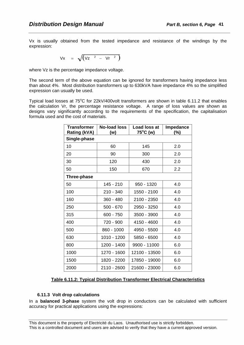
Distribution Design Manual Part B, section 6, Page
This document is the property of Electricité du Laos. Unauthorised use is strictly forbidden. This is a controlled document and users are advised to verify that they have a current approved version.
41
Vx is usually obtained from the tested impedance and resistance of the windings by the expression:
( )22 VrVzVx −= where Vz is the percentage impedance voltage. The second term of the above equation can be ignored for transformers having impedance less than about 4%. Most distribution transformers up to 630kVA have impedance 4% so the simplified expression can usually be used. Typical load losses at 75oC for 22kV/400volt transformers are shown in table 6.11.2 that enables the calculation Vr, the percentage resistance voltage. A range of loss values are shown as designs vary significantly according to the requirements of the specification, the capitalisation formula used and the cost of materials.
Transformer Rating (kVA)
No-load loss (w)
Load loss at 75oC (w)
Impedance (%)
Single-phase 10 60 145 2.0
20 90 300 2.0
30 120 430 2.0
50 150 670 2.2
Three-phase 50 145 - 210 950 - 1320 4.0
100 210 - 340 1550 - 2100 4.0
160 360 - 480 2100 - 2350 4.0
250 500 - 670 2950 - 3250 4.0
315 600 - 750 3500 - 3900 4.0
400 720 - 900 4150 - 4600 4.0
500 860 - 1000 4950 - 5500 4.0
630 1010 - 1200 5850 - 6500 4.0
800 1200 - 1400 9900 - 11000 6.0
1000 1270 - 1600 12100 - 13500 6.0
1500 1820 - 2200 17850 - 19000 6.0
2000 2110 - 2600 21600 - 23000 6.0
Table 6.11.2: Typical Distribution Transformer Electrical Characteristics
6.11.3 Volt drop calculations In a balanced 3-phase system the volt drop in conductors can be calculated with sufficient accuracy for practical applications using the expressions:
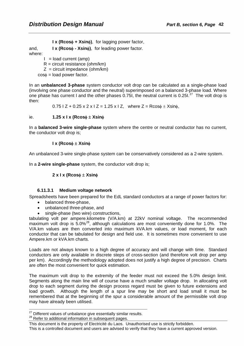
Distribution Design Manual Part B, section 6, Page
This document is the property of Electricité du Laos. Unauthorised use is strictly forbidden. This is a controlled document and users are advised to verify that they have a current approved version.
42
I x (Rcosφ + Xsinφ), for lagging power factor, and, I x (Rcosφ - Xsinφ), for leading power factor. where:
I = load current (amp) R = circuit resistance (ohm/km) Z = circuit impedance (ohm/km)
cosφ = load power factor. In an unbalanced 3-phase system conductor volt drop can be calculated as a single-phase load (involving one phase conductor and the neutral) superimposed on a balanced 3-phase load. Where one phase has current I and the other phases 0.75I, the neutral current is 0.25I.27 The volt drop is then: 0.75 I Z + 0.25 x 2 x I Z = 1.25 x I Z, where Z = Rcosφ ± Xsinφ, ie. 1.25 x I x (Rcosφ ± Xsinφ In a balanced 3-wire single-phase system where the centre or neutral conductor has no current, the conductor volt drop is; I x (Rcosφ ± Xsinφ An unbalanced 3-wire single-phase system can be conservatively considered as a 2-wire system. In a 2-wire single-phase system, the conductor volt drop is; 2 x I x (Rcosφ ± Xsinφ
6.11.3.1 Medium voltage network Spreadsheets have been prepared for the EdL standard conductors at a range of power factors for:
• balanced three-phase, • unbalanced three-phase, and • single-phase (two wire) constructions,
tabulating volt per ampere.kilometre (V/A.km) at 22kV nominal voltage. The recommended maximum volt drop is 5.0%28, although calculations are most conveniently done for 1.0%. The V/A.km values are then converted into maximum kVA.km values, or load moment, for each conductor that can be tabulated for design and field use. It is sometimes more convenient to use Ampere.km or kVA.km charts. Loads are not always known to a high degree of accuracy and will change with time. Standard conductors are only available in discrete steps of cross-section (and therefore volt drop per amp per km). Accordingly the methodology adopted does not justify a high degree of precision. Charts are often the most convenient for quick estimation. The maximum volt drop to the extremity of the feeder must not exceed the 5.0% design limit. Segments along the main line will of course have a much smaller voltage drop. In allocating volt drop to each segment during the design process regard must be given to future extensions and load growth. Although the length of a spur line may be short and load small it must be remembered that at the beginning of the spur a considerable amount of the permissible volt drop may have already been utilised. 27 Different values of unbalance give essentially similar results. 28 Refer to additional information in subsequent pages.

Distribution Design Manual Part B, section 6, Page
This document is the property of Electricité du Laos. Unauthorised use is strictly forbidden. This is a controlled document and users are advised to verify that they have a current approved version.
43
Spreadsheets and Ampere.km charts for:
• three-phase 3-wire balanced load • three-phase 3-wire unbalanced load • single-phase 2-wire,
are shown in Appendix B 6.5. Note that the charts are for 1.0% volt drop. These charts are drawn for the load concentrated at the end of the line (end load) which is appropriate for segments of a main line. For load that is distributed along the segment the permissible distance or load may be doubled. The two effects may be combined as an equivalent end load. For a segment, the percentage volt drop is given by proportion of the permissible current or distance multiplied by 1.0%. The simple network below illustrates the method of calculation by using load moments at each node.
Cumulative load at: C = 25amp B = 45amp A = 50amp S = 57amp Ampere.km for 1.0% volt drop, balanced three-phase load: Conductor Power factor 0.85 Power factor 0.95 WOLF 350 403 MINK 187 195 Section volt drops: BC (25x8+10x8x0.5)/187 = 1.28% (25x8+10x8x0.5)/195 = 1.23% AB (45x9.5+3x9.5x0.5)/350 = 1.26% (45x9.5+3x9.5x0.5)/403 = 1.10% SA (50x15+7x15x0.5)/350 = 2.29% (50x15+7x15x0.5)/403 = 1.99% Total volt drop to C 4.83% 4.32% Note that the total MV voltage drop must not exceed the allowable 5% limit. When a spur line is added to an existing network or extended the voltage drop on both the spur and the main line must be checked to be within limits. Note also the benefit to be gained by operating the network at a better power factor. On an existing network with poor power factor it may be possible to add additional load without increasing volt drop by improvement of the power factor.
S A B C15 km WOLF 9.5 km WOLF
8 km MINK
7 amp 3 amp 10 amp
2 amp 10 amp 25 amp
Distributed load End load
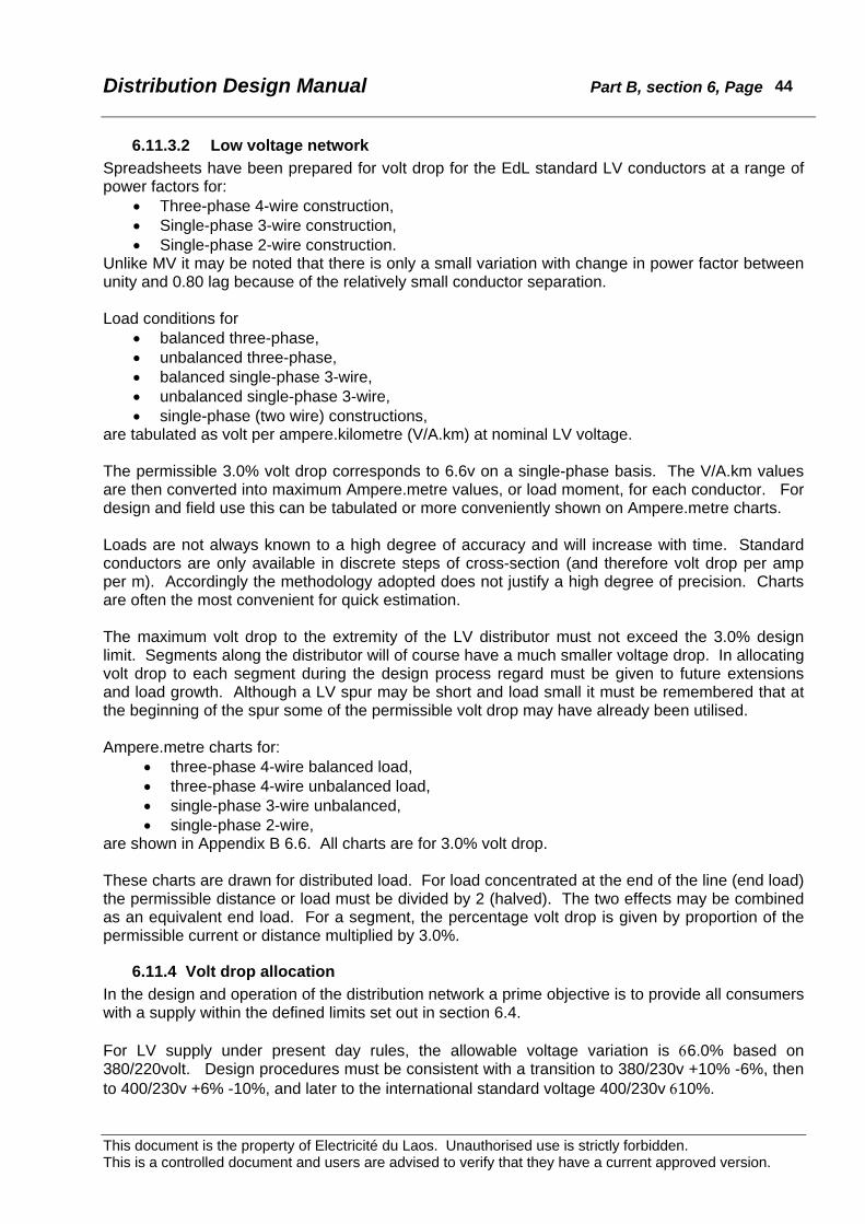
Distribution Design Manual Part B, section 6, Page
This document is the property of Electricité du Laos. Unauthorised use is strictly forbidden. This is a controlled document and users are advised to verify that they have a current approved version.
44
6.11.3.2 Low voltage network Spreadsheets have been prepared for volt drop for the EdL standard LV conductors at a range of power factors for:
• Three-phase 4-wire construction, • Single-phase 3-wire construction, • Single-phase 2-wire construction.
Unlike MV it may be noted that there is only a small variation with change in power factor between unity and 0.80 lag because of the relatively small conductor separation. Load conditions for
• balanced three-phase, • unbalanced three-phase, • balanced single-phase 3-wire, • unbalanced single-phase 3-wire, • single-phase (two wire) constructions,
are tabulated as volt per ampere.kilometre (V/A.km) at nominal LV voltage. The permissible 3.0% volt drop corresponds to 6.6v on a single-phase basis. The V/A.km values are then converted into maximum Ampere.metre values, or load moment, for each conductor. For design and field use this can be tabulated or more conveniently shown on Ampere.metre charts. Loads are not always known to a high degree of accuracy and will increase with time. Standard conductors are only available in discrete steps of cross-section (and therefore volt drop per amp per m). Accordingly the methodology adopted does not justify a high degree of precision. Charts are often the most convenient for quick estimation. The maximum volt drop to the extremity of the LV distributor must not exceed the 3.0% design limit. Segments along the distributor will of course have a much smaller voltage drop. In allocating volt drop to each segment during the design process regard must be given to future extensions and load growth. Although a LV spur may be short and load small it must be remembered that at the beginning of the spur some of the permissible volt drop may have already been utilised. Ampere.metre charts for:
• three-phase 4-wire balanced load, • three-phase 4-wire unbalanced load, • single-phase 3-wire unbalanced, • single-phase 2-wire,
are shown in Appendix B 6.6. All charts are for 3.0% volt drop. These charts are drawn for distributed load. For load concentrated at the end of the line (end load) the permissible distance or load must be divided by 2 (halved). The two effects may be combined as an equivalent end load. For a segment, the percentage volt drop is given by proportion of the permissible current or distance multiplied by 3.0%.
6.11.4 Volt drop allocation In the design and operation of the distribution network a prime objective is to provide all consumers with a supply within the defined limits set out in section 6.4. For LV supply under present day rules, the allowable voltage variation is 66.0% based on 380/220volt. Design procedures must be consistent with a transition to 380/230v +10% -6%, then to 400/230v +6% -10%, and later to the international standard voltage 400/230v 610%.

Distribution Design Manual Part B, section 6, Page
This document is the property of Electricité du Laos. Unauthorised use is strictly forbidden. This is a controlled document and users are advised to verify that they have a current approved version.
45
Under load conditions all parts of the network will suffer voltage drop from the impedance of the lines, cables and transformers. Both resistance and reactance should be taken into account. Poor power factor results in increased current for a given real load that contributes to the volt drop. It is of critical importance to ensure that consumers at the extremities of the network receive a satisfactory supply (ie. voltage within the defined limits) at both maximum load and network minimum load conditions. The greatest volt drop occurs at peak load and is the basis for setting on-load and off-load tapping switches and the maximum limits for volt drop to the network extremities. Consideration must also be given to the voltage conditions at minimum load to ensure that excessively high voltage is not supplied. Consumers close to the major substation will not experience the same range of voltage variation but again it is necessary to ensure that excessively high voltage is not supplied. The voltage drop within a MV and LV distribution network comprises:
• Conductor resistance drop, • Conductor reactance drop, and • Transformer regulation (resistance and reactance drop)
6.11.4.1 Supply busbar voltage At the major substation the 22kV supply busbar is usually controlled by automatic on-load tapchange (OLTC, or TCOL) equipment on the high voltage side of the 115/22kV transformers. The busbar voltage can be maintained constant at the pre-set value subject to:
• The transformer tap interval, usually 1.25% (275volt at nominal 22kV) • The deadband of the voltage control relay (VRR). This is customarily set at
approximately 1.6% of nominal voltage to avoid hunting and excessive operation of the tapchange equipment.
The pre-set busbar voltage is most effectively set a small margin (approximately 2.0%) higher than the nominal value, to provide an additional margin for volt drop along the feeder. For LV consumers close to the major substation any excessive voltage is adjusted by using a bucking tap29 on the local distribution transformer.
6.11.4.2 Distribution transformer ratio Standard distribution transformers have a 400/230v or 230v secondary output voltage that is 5.263% higher than the nominal 220v LV supply voltage30. For a 220volt network this voltage boost can be utilised to compensate for the transformer regulation and some of the voltage loss along the MV feeder and LV distributor. When these transformers are used in a 230volt network the effective transformer ratio is 1.00. If 415/240volt transformers are used the voltage boost is 3.750%. These concepts are illustrated in Figure 6.11.4.3.
29 A “plus” tapping on the transformer designed to adjust the secondary output voltage to the standard value when the primary voltage is greater than nominal. The negative tappings are similarly sometimes referred to as boost taps. 30 Calculated on phase-phase voltages.

Distribution Design Manual Part B, section 6, Page
This document is the property of Electricité du Laos. Unauthorised use is strictly forbidden. This is a controlled document and users are advised to verify that they have a current approved version.
46
6.11.4.3 Determining factors The voltage at the consumer switchboard varies according to:
• ** Target voltage at consumer switchboard • ** Allowable voltage variation at consumer switchboard • # Nominal MV busbar voltage • # Pre-set MV busbar voltage • # Major substation OLTC tapping interval • # Major substation OLTC deadband • MV feeder maximum volt drop • Low load as % of Full Load • Distribution transformer off load taps • Transformer impedance • LV Distributor maximum volt drop • Serviceline and consumer servicemain volt drop • Load power factor
The target voltage at the consumer switchboard and the permissible variation are defined by legislation and cannot be extended. The items above marked ** are regulatory limits that must be satisfied and those marked # are network parameters that are generally fixed as far as the distribution designer is concerned. The distribution transformer off-load taps should not be used to conceal excessive LV or MV volt drop, as at periods of low load the voltage may rise above statutory the limit and shorten the life of consumer appliances. The power factor of the load has a significant impact on the voltage drop in line/cables and also on transformer regulation. Recommended network design values for adoption by EdL are shown in Table 6.11.4.3. These have been selected primarily to ensure the delivery of statutory voltage to consumers, but also on an equitable and economic allocation to different parts of the network. The table is derived from the sample spreadsheets shown in Appendix B 6.4 to show the effect of changes in the variables for selected power factors. The allowable MV feeder volt drop has been selected as 5%. It may be possible to increase this value at a later date when: • Standard LV supply voltage has been set at 230volt 610%, and • LV distributors are of adequate cross-section and not excessively long, and • Distribution network power factor is improved to 0.90 or better The distribution network should be designed to eventually operate at power factor of 0.95 or better at full load. Although permissible volt drop is greater at or near unity power factor, 0.95 is chosen as an economic and achievable compromise. In the initial stages of network development when peak loads are lower and good power factor cannot always be achieved, voltage drop calculations for conductor cross-section and maximum allowable lengths should be for load power factor 0.80. When limits are reached from subsequent load growth, progressive correction of power factor will avoid the need to reconstruct lines or add extra transformer capacity.

Distribution Design Manual Part B, section 6, Page
This document is the property of Electricité du Laos. Unauthorised use is strictly forbidden. This is a controlled document and users are advised to verify that they have a current approved version.
47
Insert Figure 6.11.4.3, Voltage Profile for Distribution System
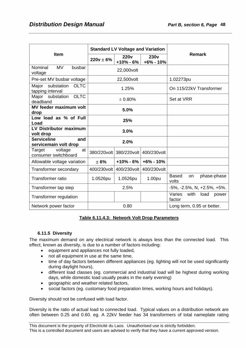
Distribution Design Manual Part B, section 6, Page
This document is the property of Electricité du Laos. Unauthorised use is strictly forbidden. This is a controlled document and users are advised to verify that they have a current approved version.
48
Standard LV Voltage and VariationItem
220v ± 6% 220v +10% - 6%
230v +6% - 10%
Remark
Nominal MV busbar voltage 22,000volt
Pre-set MV busbar voltage 22,500volt 1.02273pu Major substation OLTC tapping interval 1.25% On 115/22kV Transformer
Major substation OLTC deadband ± 0.80% Set at VRR
MV feeder maximum volt drop 5.0%
Low load as % of Full Load 25%
LV Distributor maximum volt drop 3.0%
Serviceline and servicemain volt drop 2.0%
Target voltage at consumer switchboard 380/220volt 380/220volt 400/230volt
Allowable voltage variation ± 6% +10% - 6% +6% - 10%
Transformer secondary 400/230volt 400/230volt 400/230volt
Transformer ratio 1.0526pu 1.0526pu 1.00pu Based on phase-phase volts
Transformer tap step 2.5% -5%, -2.5%, N, +2.5%, +5%.
Transformer regulation Varies with load power factor
Network power factor 0.80 Long term, 0.95 or better.
Table 6.11.4.3: Network Volt Drop Parameters
6.11.5 Diversity The maximum demand on any electrical network is always less than the connected load. This effect, known as diversity, is due to a number of factors including:
• equipment and appliances not fully loaded, • not all equipment in use at the same time, • time of day factors between different appliances (eg. lighting will not be used significantly
during daylight hours), • different load classes (eg. commercial and industrial load will be highest during working
days, while domestic load usually peaks in the early evening) • geographic and weather related factors, • social factors (eg. customary food preparation times, working hours and holidays).
Diversity should not be confused with load factor. Diversity is the ratio of actual load to connected load. Typical values on a distribution network are often between 0.25 and 0.60. eg. A 22kV feeder has 34 transformers of total nameplate rating

Distribution Design Manual Part B, section 6, Page
This document is the property of Electricité du Laos. Unauthorised use is strictly forbidden. This is a controlled document and users are advised to verify that they have a current approved version.
49
2652kVA. The observed maximum load at the supply substation is 29amp. The calculated diversity is:
42.02625
32229=
××
The above factor is also known as the Transformer Utilisation Factor (TUF). In the example, at the time of the feeder peak load only 42% of the installed transformer capacity contributes to the peak. While some transformers may be fully loaded others have only a small load. This may be unavoidable, as at other times the lightly loaded transformers may be fully loaded. A TUF greater than about 0.5 is normally not achievable because:
• time-of-day differences in the peak loading on different transformers, • transformer ratings are in discrete steps, • the need to provide sufficient transformer capacity to allow for the starting of large
motors, • provision for load growth.
Diversity effects enable the use of a smaller conductor or longer feeder than the installed transformer capacity would indicate. Diversity effects apply at all levels of an electricity network. In a consumer installation diversity may be applied to the sub-circuits as well as the mains cables. On a LV distributor the effects of diversity are greater with increased number of consumers. At a distribution transformer the diversity will be greater where there are more consumers. Similar effects apply upstream in the MV networks, major substations, the transmission grid, and ultimately back to the generation source. The effect of diversity is sometimes expressed as After Diversity Maximum Demand (ADMD). This is the contribution to the group peak load from an installation, particular component or circuit. ADMD may be expressed as kW or Amperes. For a distribution transformer supplying a number of installations ADMD is the transformer peak load divided by the number of installations. eg. A 100kVA transformer has a measured maximum demand of 89amp and supplies 105 consumer installations with total connected load 237kVA.
kVA59.0105
3400.089ADMD =××
=
26.0237
3400.089Diversity =××
=
6.11.6 Estimation of maximum demand on consumer installations The estimation of maximum demand from an individual consumer installation must be based upon experience as well as the connected load. Experience in Laos PDR and many other countries has shown that in newly reticulated areas load growth in individual consumer installations may be very high within the first 5 years of electrification. An appropriate allowance either initially or by the provision of easily expanded capacity should be incorporated in new designs. The bases below may be used until more reliable information is available to EdL. Alternative methods may be used particularly for non-domestic installations provided these take into account all relevant information and are certified by a qualified person. The following procedure should be used in the selection of the rating of internal mains cables and service line sizes with an additional check for voltage drop compliance.

Distribution Design Manual Part B, section 6, Page
This document is the property of Electricité du Laos. Unauthorised use is strictly forbidden. This is a controlled document and users are advised to verify that they have a current approved version.
50
Domestic installations:
Indoor lighting 60w per lamp for the first 10 fittings + 50% of the remainder.
Outdoor lighting 75% of the connected load.
Socket outlets 2.5amp for each of the first 4 circuits from the switchboard or sub-board + 1.5amp for each of the remaining circuits.
Air conditioners Connected load for the first two units + 50% of the balance.
Instantaneous water heaters 33.3% of connected load.
Storage water heaters Connected load.
Water pumps Full load of largest motor + 50% of balance of connected load. In every case the assessed load on any sub-circuit need not exceed the rating of the sub-circuit fuse or mcb. The assessed load for the installation need not exceed the rating of the main fuse or mcb.
Table 6.11.6a: Load Estimation – Domestic Installations Non-domestic installations Indoor Lighting Full connected load Outdoor lighting 75% of the connected load
Socket outlets up to 10amp 10amp for each circuit from the switchboard or sub-board for the first 5 circuits + 5amp for each additional circuit from the switchboard or sub-board.
Socket outlets exceeding 10amp Full current rating of the highest rated circuit from the switchboard or sub-board + 75% of full current rating of the remainder.
Arc welders
100% of each rated primary current for the two largest machines + 85% of rated primary current for the next largest machine + 70% of rated primary current for the next largest machine + 60% of rated primary current for all other machines.
Air conditioners Connected load for the first five units + 50% of the balance Instantaneous water heaters 33.3% of connected load Storage water heaters Connected load
Motors Full load of largest motor + 75% of full load of second largest + 50% of full load of remainder
In every case the assessed load on any sub-circuit need not exceed the rating of the sub-circuit fuse or mcb. The assessed load for the installation need not exceed the rating of the main fuse or mcb.
Table 6.11.6b: Load Estimation – Non-domestic Installations Examples: Small domestic residence comprising 4 lights and 2 socket outlet circuits. 4 - Lights 4 @ 60w = 240watt 2 - Sockets 2 @ 2.5amp = 2 x 2.5 x 220 = 1100watt, After diversity total = 1340watt

Distribution Design Manual Part B, section 6, Page
This document is the property of Electricité du Laos. Unauthorised use is strictly forbidden. This is a controlled document and users are advised to verify that they have a current approved version.
51
Medium domestic residence comprising 10 lights, 4 socket outlet circuits, 1500w airconditioner, and 500w pump. 10 - Lights 10 @ 60w = 600watt 4 - Sockets 4 @ 2.5amp = 2 x 2.5 x 220 = 1100watt air con. 1 x 1500w = 1500watt pump 1 x 500w = 500watt, After diversity total = 3700watt Large domestic residence comprising 25 lights, 7 socket outlet circuits, 3 - 1500w airconditioners, and 500w pump. 25 - Lights 10 @ 60w + 15 @ 60w x 0.5 = 1050watt 7 - Sockets 4 @ 2.5amp + 3 @ 1.5 amp = 4 x 2.5 x 220 + 3 x 1.5 x 220 = 3190watt air con. 2 x 1500w + 1 x 1500 x 0.5 = 3750watt pump 1 x 500w = 500watt, After diversity total = 8490watt
6.11.7 Estimation of transformer maximum demand The after diversity maximum demand on a distribution transformer is considerably less than the assessed load for the individual consumer installations. Experience has shown that for domestic installations the following basis can be used:
Up to 5 houses: 50% of the sum of the installation assessed loads, 5 to 10 houses: 40% of the sum of the installation assessed loads, more than 10 houses 33% of the sum of the installation assessed loads.
Non domestic installations may contribute very little to the evening time demand on a transformer if the business is an office or factory, but a small retail shop could be open. The contribution from each non-domestic installation should be considered for the local circumstances. Example: 100kVA transformer supplying 55 small houses, 11 medium houses, 6 large houses, 6 small shops and a government administration building. 53 x 1340 x 33% = 23,437watt 11 x 3700 x 33% = 13,431watt 6 x 8490 x 40% = 20,376watt 6 x 4000 x 40% (shops) = 9,600watt government office = nil After diversity total = 66,843watt A distribution network designer needs a basis to assess the maximum load that each segment should be rated for if it is to operate within the design parameters. Items include:
• consumer metering, • consumer service lines, • LV distributors, • transformer LV overload protection, • distribution transformers, • MV feeders and switchgear, • MV feeder protection equipment including relays.
The installation maximum demands and ADMD appropriate to different consumer classes and localities will vary with time as economic and social circumstances change. Experience in Laos PDR and many other countries has shown that in newly reticulated areas load growth may be very high within the first 5 years of electrification.
Distribution Design Manual Part B, section 6, Page
This document is the property of Electricité du Laos. Unauthorised use is strictly forbidden. This is a controlled document and users are advised to verify that they have a current approved version.
52
6.11.8 Load Balance To achieve maximum utilisation of the network it is important to have the loading on each phase of a circuit as even as possible. Where loads are predominantly single phase, balance changes with time and load level. Usually the aim is for best balance at peak load as in this way voltage drop and losses are minimised. During construction similar numbers of single-phase connections should be made to each phase in turn. This applies to consumer service lines, LV distributors, transformers and MV spurs. At LV, initially a numerical balance of connections (both single and three phase) should be made at every pole. Unfortunately this will not always give satisfactory balance, and some trial and error adjustments will often be required. Techniques for improving LV balance include:
• Move single phase connections to another phase • Interchange heavily loaded single phase connections with light loaded • On three phase connections move each connection to the adjacent phase ( to keep the
same phase rotation for motors) • Monitor neutral current on a three phase LV system (a zero or small neutral current
indicates good balance). It should be noted that even if the overall LV load on a transformer is reasonably balanced, individual distributors might not be. This is particularly so if the distributors have sections of two or three wire construction. Also, the balance will change along the length of a distributor – this can be checked by measuring the neutral current in different sections of the distributor. It is possible for there to be significant neutral current in a section downstream from where there is good overall balance. Improving the balance in the offending sections can reduce voltage drop and losses. At MV, balance will generally be satisfactory if the LV system is well balanced. Care should be taken to spread single-phase spurs across all three phases so that about the same transformer kVA rating is connected to each pair of phase conductors along the line route.
6.11.9 Power factor
In an ac system the power delivered is 3 E I cosφ kW, where cosφ is the power factor with real component kW and quadrature (imaginary) component kVAr. The current loading and hence the equipment rating is given by kVA. Poor power factor significantly increases system losses because of the higher current for the same “real” or effective power delivered. The benefits from power factor improvement include;
• Reduced system I2R losses • Reduced voltage drop on MV and LV lines, therefore more stable voltage for
consumers, • Reduced ampere (or kVA) load on transformers that directly reduces transformer
losses, and may avoid overloading or enable the use of a smaller transformer, • Deferment of capital expenditure on upgrading the capacity of generation plant,
transmission lines, major substation transformers, MV lines/cables, distribution transformers, and LV network.
The payback period (ie. the time for the savings to equal the capital cost) for power factor improvement is often very short – typically one or two years. Increased consumption and confidence in the quality of the power supply can also be anticipated although these may be less tangible benefits.

Distribution Design Manual Part B, section 6, Page
This document is the property of Electricité du Laos. Unauthorised use is strictly forbidden. This is a controlled document and users are advised to verify that they have a current approved version.
53
Power factor can be readily improved by the insertion of capacitors that generate reactive energy that is measured as kVAr.
Figure 6.11.9: Power Factor Diagram
The required capacitor rating to improve from a known power factor to a target value can be calculated as follows. From Figure 6.11.9, to improve the power factor from cosφ2 to cosφ1, it is necessary to change the quadrature component from kVAr1 to kVAr2. By inspection from the diagram the amount of kVAr to be inserted is: KVAr2 – kVAr1 = kW tanφ2 - kW tanφ1 = kW (tanφ2 - tanφ1) Table 6.10.9a is a look up table of values of (tanφ2 - tanφ1). To determine the required capacitor kVAr rating, use the table to obtain the multiplier on the intersection between the raw power factor and the target power factor, then multiply by the real power in kW.
Target Power Factor Raw Power Factor 0.70 0.75 0.80 0.85 0.90 0.92 0.94 0.95 0.96 0.98 1.00
0.40 1.271 1.409 1.541 1.672 1.807 1.865 1.928 1.963 2.000 2.088 2.2910.45 0.964 1.103 1.235 1.365 1.500 1.559 1.622 1.656 1.693 1.781 1.9850.50 0.712 0.850 0.982 1.112 1.248 1.306 1.369 1.403 1.440 1.529 1.7320.55 0.498 0.637 0.768 0.899 1.034 1.092 1.156 1.190 1.227 1.315 1.5180.60 0.313 0.451 0.583 0.714 0.849 0.907 0.970 1.005 1.042 1.130 1.3330.65 0.149 0.287 0.419 0.549 0.685 0.743 0.806 0.840 0.877 0.966 1.1690.70 0.138 0.270 0.400 0.536 0.594 0.657 0.692 0.729 0.817 1.0200.75 0.132 0.262 0.398 0.456 0.519 0.553 0.590 0.679 0.8820.80 0.130 0.266 0.324 0.387 0.421 0.458 0.547 0.7500.85 0.135 0.194 0.257 0.291 0.328 0.417 0.6200.90 0.058 0.121 0.156 0.193 0.281 0.484
Table 6.11.9a: Multiplier for Power Factor Improvement
Example. A 75kW load of raw power factor 0.75 is to be improved to 0.95. Required correction = 0.553 x 75 = 41.5kVAr.
φ1 φ2
KVA2
KVA1
kW
Capacitor kVAR kVAr2 – kVAr1
KVAr1
kVAr2
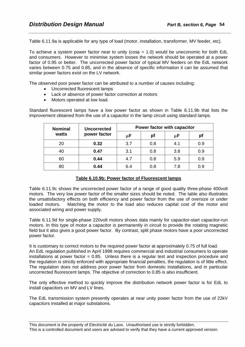
Distribution Design Manual Part B, section 6, Page
This document is the property of Electricité du Laos. Unauthorised use is strictly forbidden. This is a controlled document and users are advised to verify that they have a current approved version.
54
Table 6.11.9a is applicable for any type of load (motor, installation, transformer, MV feeder, etc). To achieve a system power factor near to unity (cosφ = 1.0) would be uneconomic for both EdL and consumers. However to minimise system losses the network should be operated at a power factor of 0.95 or better. The uncorrected power factor of typical MV feeders on the EdL network varies between 0.75 and 0.85, and in the absence of specific information it can be assumed that similar power factors exist on the LV network. The observed poor power factor can be attributed to a number of causes including:
• Uncorrected fluorescent lamps • Lack or absence of power factor correction at motors • Motors operated at low load.
Standard fluorescent lamps have a low power factor as shown in Table 6.11.9b that lists the improvement obtained from the use of a capacitor in the lamp circuit using standard lamps.
Power factor with capacitor Nominal watts
Uncorrected power factor μF pf μF pf
20 0.32 3.7 0.8 4.1 0.9
40 0.47 3.1 0.8 3.8 0.9
60 0.44 4.7 0.8 5.9 0.9
80 0.44 6.4 0.8 7.8 0.9
Table 6.10.9b: Power factor of Fluorescent lamps Table 6.11.9c shows the uncorrected power factor of a range of good quality three-phase 400volt motors. The very low power factor of the smaller sizes should be noted. The table also illustrates the unsatisfactory effects on both efficiency and power factor from the use of oversize or under loaded motors. Matching the motor to the load also reduces capital cost of the motor and associated wiring and power supply. Table 6.11.9d for single-phase 220volt motors shows data mainly for capacitor-start capacitor-run motors. In this type of motor a capacitor is permanently in circuit to provide the rotating magnetic field but it also gives a good power factor. By contrast, split phase motors have a poor uncorrected power factor. It is customary to correct motors to the required power factor at approximately 0.75 of full load. An EdL regulation published in April 1998 requires commercial and industrial consumers to operate installations at power factor = 0.85. Unless there is a regular test and inspection procedure and the regulation is strictly enforced with appropriate financial penalties, the regulation is of little effect. The regulation does not address poor power factor from domestic installations, and in particular uncorrected fluorescent lamps. The objective of correction to 0.85 is also insufficient. The only effective method to quickly improve the distribution network power factor is for EdL to install capacitors on MV and LV lines. The EdL transmission system presently operates at near unity power factor from the use of 22kV capacitors installed at major substations.
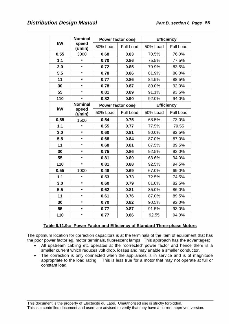
Distribution Design Manual Part B, section 6, Page
This document is the property of Electricité du Laos. Unauthorised use is strictly forbidden. This is a controlled document and users are advised to verify that they have a current approved version.
55
Power factor cosφ Efficiency kW
Nominal speed (r/min) 50% Load Full Load 50% Load Full Load
0.55 3000 0.68 0.83 70.5% 76.0% 1.1 “ 0.70 0.86 75.5% 77.5% 3.0 “ 0.72 0.85 79.9% 83.5% 5.5 “ 0.78 0.86 81.9% 86.0% 11 “ 0.77 0.86 84.5% 88.5% 30 “ 0.78 0.87 89.0% 92.0% 55 “ 0.81 0.89 91.1% 93.5%
110 “ 0.82 0.90 92.0% 94.0% Power factor cosφ Efficiency
kW Nominal speed (r/min) 50% Load Full Load 50% Load Full Load
0.55 1500 0.54 0.75 68.5% 73.0% 1.1 “ 0.55 0.77 77.5% 79.55 3.0 “ 0.60 0.81 80.0% 82.5% 5.5 “ 0.68 0.84 87.0% 87.0% 11 “ 0.68 0.81 87.5% 89.5% 30 “ 0.75 0.86 92.5% 93.0% 55 “ 0.81 0.89 63.6% 94.0%
110 “ 0.81 0.88 92.5% 94.5% 0.55 1000 0.48 0.69 67.0% 69.0% 1.1 “ 0.53 0.73 72.5% 74.5% 3.0 “ 0.60 0.79 81.0% 82.5% 5.5 “ 0.62 0.81 85.0% 86.0% 11 “ 0.61 0.76 87.0% 89.5% 30 “ 0.70 0.82 90.5% 92.0% 55 “ 0.77 0.87 91.5% 93.0%
110 “ 0.77 0.86 92.55 94.3%
Table 6.11.9c: Power Factor and Efficiency of Standard Three-phase Motors The optimum location for correction capacitors is at the terminals of the item of equipment that has the poor power factor eg. motor terminals, fluorescent lamps. This approach has the advantages:
• All upstream cabling etc operates at the “corrected’ power factor and hence there is a smaller current which reduces volt drop, losses and may enable a smaller conductor.
• The correction is only connected when the appliances is in service and is of magnitude appropriate to the load rating. This is less true for a motor that may not operate at full or constant load.

Distribution Design Manual Part B, section 6, Page
This document is the property of Electricité du Laos. Unauthorised use is strictly forbidden. This is a controlled document and users are advised to verify that they have a current approved version.
56
Power factor cosφ at Full Load kW
Nominal speed (r/min) Split-phase CSCR*
Efficiency
0.37 3000 0.55 “ 0.98 63% 1.1 “ 0.90 73% 2.2 “ 0.93 73%
0.37 1500 0.68 0.75 64% 0.55 “ 0.74 0.87 67% 1.1 “ 0.95 71% 2.2 “ 0.97 76%
0.37 1000 0.99 70% 0.55 “ 0.84 68% 1.1 “ 0.85 71%
CSCR = capacitor start capacitor run
Table 6.11.9d: Power Factor and Efficiency of Standard Capacitor-start
Capacitor-run Single-phase Motors An alternative approach on a commercial or industrial consumer installation is to have centrally located power factor correction equipment that may be automatically switched in increments to suit the actual load. This approach will:
• require less installed kVAr than individual correction, and • may be more economic where there is a high diversity between individual items in an
installation. However, it should be noted that all cabling downstream of the power factor correction plant must be rated for current as for the uncorrected condition. A combination of some individual and some centralised correction can be adopted. The above approaches impose the cost of power factor correction upon the consumer, and in general necessitate a financial incentive to the consumer of reduced charges for good power factor or penalty charges for non-compliance. Additional metering costs, both equipment and billing, will be incurred by the electric supply organisation (EdL). Where the correction of power factor is not imposed directly on the consumer, the next best approach is to provide correction equipment on the LV network. Customarily this is installed at or near the distribution transformer, but it is electrically more effective if distributed in smaller blocks along the LV line. Capacitors can also be installed on the MV network at selected points along each MV feeder. This may offer the least cost solution for reducing MV losses but of course does not reduce losses in transformers or on the LV network, both of which need to be rated for the kVA load not the kW load.

Distribution Design Manual Part B, section 6, Page
This document is the property of Electricité du Laos. Unauthorised use is strictly forbidden. This is a controlled document and users are advised to verify that they have a current approved version.
57
6.12 Environmental Data The major environmental conditions for overhead line construction in Lao PDR are weather related. These include:
• Temperature • Rainfall, • Wind, • Sunshine, • Thunderstorms.
Other environmental factors that must be considered are altitude (although this is commonly an influence on weather effects), vegetation, geological (soil strength and stability), earthquakes, scenic, and cultural.
6.12.1 Weather Climate data for 18 major weather recording stations throughout Lao PDR has been compiled and published separately.31 This is summarised Appendix B 6.7. For the design of overhead distribution lines it is necessary to consider the likely extreme conditions to ensure that the network remains serviceable under reasonably credible circumstances. Care must be taken not to select unduly conservative values such that supply failures will not occur. To do so would be very expensive and uneconomic. Lao PDR has a range of climatic conditions particularly varying with altitude. Although the major population centres are at altitudes between 150m and 300m, some reticulation is above 1000m. For simplicity and to avoid of the risk of misinterpretation is desirable to have one set of design (loading) conditions for all areas. This is justified, as there are only small penalties in universal parameters. This does not preclude the use of higher values in specific circumstances where there are unusual local factors or detailed information. The following design values shall be used. Temperature Extreme maximum 45oC Mean maximum 32oC Mean 25oC Mean minimum 16oC Extreme minimum 0oC Annual Rainfall 1300mm to 3000mm Wind Maximum speed 40metre/sec Design wind speed for distribution lines 27.5metre/sec Mean wind speed 2.0metre/sec Solar radiation Annual sunshine 2400hours
31 “Meteorological Information by 20 Years”, EdL, compiled by Worley International, February 2000. Period is 1979 to 1998 although the duration of records varies from site to site.

Distribution Design Manual Part B, section 6, Page
This document is the property of Electricité du Laos. Unauthorised use is strictly forbidden. This is a controlled document and users are advised to verify that they have a current approved version.
58
Solar intensity 1000watt/m2 Isokeraunic level Mean annual thunderstorm days 65 Maximum annual thunderstorm days 150
6.12.2 Vegetation Tree growth in the vicinity of distribution lines that are not insulated for full working voltage must be controlled to avoid disruption to supply from electrical flashover, and mechanical damage due to contact and burn damage. On fully insulated lines heavy branches that may rub against conductors must also be removed to avoid mechanical damage to the insulation system. Tree and vegetation control limits are shown in Figures 8.1 and 8.2 in the Clearance Regulations. The Regulations recognise that some species (eg. bamboo) are extremely fast growing and should not be allowed below electric lines. In general trees and other vegetation must not encroach closer than 2.5m of any position to which a conductor may sag or swing due to wind and temperature effects. Tree and vegetation cutting should always be at least 2.0m greater than the minimum distance. Trees that are within falling distance of the still air position of conductors must also be removed. Particular note should be taken on sloping ground where trees some distance from a line may impose a threat. In environmentally sensitive areas (eg. Biodiversity parks) it may be unacceptable to remove all vegetation that threatens a distribution line. In such cases it may be appropriate to accept occasional damage from falling trees or branches, but pole structures should be designed to minimise cascade failures.
6.12.3 Thunderstorms Lao PDR is subject to a high level of thunderstorm activity. EdL distribution lines shall be designed to minimise damage and outages from lightning strikes. Every distribution transformer shall be fitted with surge arresters on the upstream side of the MV fuses.32 MV surge arresters shall be installed at:
• 5km intervals along feeders unless there is a distribution transformer within that distance,
• outdoor MV cable terminations (risers), • enclosed outdoor switchgear (SF6 or vacuum load break switches, reclosers,
sectionalisers), and • capacitor banks.
6.12.4 Earthquakes Seismic activity in Lao PDR is rare and of relatively low magnitude. Customary holding down arrangements against overturning due to applied conductor and/or wind forces, movement from service vibration, movement from vehicle impact, and physical security will be generally adequate for earthquake loads for distribution equipment.33
32 The alternative position at the MV bushing affords better protection against transformer damage but may result in prolonged outages to individual transformers as the result of MV fuse operation.
Distribution Design Manual Part B, section 6, Page
This document is the property of Electricité du Laos. Unauthorised use is strictly forbidden. This is a controlled document and users are advised to verify that they have a current approved version.
59
No specific design precautions are recommended for overhead distribution applications.
6.12.5 Cultural and scenic The siting of equipment must take into consideration scenic and cultural concerns. These topics are addressed in Part A of the Design Manual.
33 More sophisticated arrangements may be necessary for generation plant and transmission substations where there may be large brittle (porcelain) components and the consequences of failure are more serious and widespread.

Distribution Design Manual Part B, section 6, Page
This document is the property of Electricité du Laos. Unauthorised use is strictly forbidden. This is a controlled document and users are advised to verify that they have a current approved version.
60
6.13 Clearances For electrical clearances to ground and structures, reference should be made to the EdL “Interim Guideline for Network Electrical Safety Clearances”34. The guideline document defines minimum safety clearances under the most adverse conditions of applied (wind) load, temperature, etc. There may be particular circumstances where enhanced clearances are required. In normal circumstances somewhat larger clearances will be observed because the conductor will not be at the extreme conditions. The clearances listed in the Guideline are loosely based on “Regulations for Erection and Operation of Electrical Networks” prepared by EdL Standardisation Group, May 1991 with the assistance of EdFI35. The concept used in the EdFI document is that the minimum clearance (D) is the sum of a basic clearance (b) plus a voltage distance (t):
D = b + t
For clearance above ground the basic distance is the minimum safe distance according to the location and voltage of the line as in table 6.13.1.
Basic clearance (m) Location Conductor Type LV MV HV
Insulated 6.5 6.5 N/A Roadways and public places accessible to vehicles Bare 6.5 6.5 8.0
Insulated 5.5 5.5 N/A Cultivated land and other private places likely to be used
by vehicles Bare 5.5 5.5 7.5
Insulated 4.5 4.5 N/A Land not traversible by vehicles Bare 4.5 5.5 5.5
Table 6.13.1: Basic clearance distances
In addition the voltage clearance factor t is classified by risk or probability of flashover as in tables 6.13.2 and 6.13.3.
Voltage distance t * Risk factor Application limit t0 = 0 Fully insulated conductors
t1 = 0.005U Low probability t1 = 0 for U < 60kV
t2 = 0.010U Medium probability t2 = 0 for U < 30kV
t3 = 0.015U High probability t3 = 0 for U < 20kV * = t is expressed in metre, U in kV
Table 6.13.2: Clearance voltage factor
The t values when applied to the standard overhead line voltages in use on the EdL network are shown in table 6.13.3. 34 Revised by Worley International, August 2000. 35 Electricité de France International.

Distribution Design Manual Part B, section 6, Page
This document is the property of Electricité du Laos. Unauthorised use is strictly forbidden. This is a controlled document and users are advised to verify that they have a current approved version.
61
Voltage Voltage distance t (m)
LV, (400/230v) t1 = t2 = t3 = 0 MV, (eg.22kV) t1 = t2 = 0 t3 = 0.33
MV, (eg.34.5kV) t1 = 0 t2 = 0.35 t3 = 0.52 HV, (eg.115kV) t1 = 0.58 t2 = 1.15 t3 = 1.73 HV, (eg.230kV) t1 = 1.15 t2 = 2.30 t3 = 3.45
Table 6.13.3: Application of clearance voltage factor
In table 6.13.4 factor t3 is applied for roadways and places where vehicles may travel. In other accessible places including private land and on cultivated land factor t2 is used. Elsewhere t1 is used.
Basic distance b (m) Voltage distance t for bare conductor (m) Location Insulated
conductorBare
conductor Case LV 22kV 34.5kV 115kV
Roadways 6.5 6.5 t3 0 0.5 1.2 1.8
Public places 6.5 6.5 t2 0 0 0.3 1.2
Pathways accessible by vehicles 6.5 6.5 t3 0 0.5 1.2 1.8
Pathways not accessible by vehicles 5.5 5.5 t2 0 0 0.3 1.2
Places accessible by machinery up to 4m high 5.5 5.5 t2 0 0 0.3 1.2
Other places 4.5 4.5 t2 0 0 0.3 1.2
Land accessible only on foot 4.5 4.5 t1 0 0 0 0.6
Waterways at flood level (navigable) Mast + 1 Mast + 1 t2 0 0 0.3 1.2
Waterways at flood level (not navigable) 3 3 t2 0 0 0.3 1.2
Petrol stations and fuel storage areas Not permitted
Table 6.13.4: Overall Ground Clearance Distances
The clearances derived from the foregoing have been modified to align with practices in other countries with well developed technical standards, and the results rounded to the next 0.5m to provide a rational range of values. Clearances to buildings and other structures are also scheduled in to the EdL “Interim Guideline for Network Electrical Safety Clearances”. The values are based on a number of national safety standards.

Distribution Design Manual Part B, section 6, Page
This document is the property of Electricité du Laos. Unauthorised use is strictly forbidden. This is a controlled document and users are advised to verify that they have a current approved version.
62
Users should be aware that the clearances observed under everyday conditions must be greater than the design minimum. Experience will often indicate if the observed clearances are likely to be satisfactory under the defined extreme conditions, but specific calculations are required to make an informed decision. The sag and tension charts companion to this Design Manual can be used to estimate clearances under different temperature and wind conditions. Safe working rules and practices are described in EdL document “Safety Rules for Working Near and On Electric Network Conductors”.

Distribution Design Manual Part B, section 6, Page
This document is the property of Electricité du Laos. Unauthorised use is strictly forbidden. This is a controlled document and users are advised to verify that they have a current approved version.
63
6.14 Overhead conductors
6.14.1 Conductor materials Hard drawn stranded copper conductor was once the traditional material for overhead line construction, but has largely been replaced by aluminium. Because of cost the use of copper is now restricted to smaller insulated cables, for direct buried earthing applications, and where bi-metallic connections are to be avoided. In cables, copper is usually used in the soft drawn condition. Stranded copper conductors are commonly described by their stranding or actual cross-sectional area. Aluminium conductor is in widespread use internationally and by EdL. It usually provides the most economic conductor choice despite conductivity only 61% of commercially pure copper. Aluminium is lighter for the same cross-section than copper. For overhead line conductors aluminium is used in a high purity hardened condition. Aluminium is frequently alloyed or used in combination with other materials in the conductor to impart greater strength. Common abbreviations for conductor materials are shown in table 6.14.1a.
Name Abbreviation Conductor Type
Cu Copper (97% IACS)+
AAC All Aluminium Conductor
AAAC1120 All Aluminium Alloy (1120) Conductor
AAAC(6201) All Aluminium Alloy (6201) Conductor *
GZ Galvanised Steel
AZ Aluminised Steel
AC Aluminium Clad Steel + = International Annealed Copper Standard * = Alloy 6201 is also known as Almelec and Aldrey
Table 6.14.1a: Name Abbreviation for Conductor Types
Standard purity aluminium grade 1350 has a tensile strength in the range 160 to 185 MPa depending upon strand diameter. For enhanced strength aluminium may be alloyed with very small quantities of magnesium, copper, and silicon to produce a number of standard alloys. Nowadays the most widely used of the alloys is 112036 of tensile stress 230 to 250 MPa. Alloy 6201 has tensile stress 295MPa but is no longer in general use for overhead conductors. Traditionally composite conductors (ACSR) of grade 1350 aluminium with an inner galvanised steel core have been employed to achieve higher strength ratings particularly with small conductors. Modern alloys such as 1120 have mechanical properties that bestow similar sag and tension characteristics to ACSR of the same equivalent cross-section. By the use of a homogeneous conductor manufacturing, installation and jointing costs are simplified, and there is considerably less risk of corrosion. The installed costs of AAAC (1120) are generally comparable with ACSR. Table 6.14.1b lists useful electrical and physical properties for common conductor materials derived from AS 1746, AS 3607 and other references. More comprehensive data can be obtained from those and other Standards and manufacturers handbooks. 36 The nominal composition of alloy 1120 is Copper 0.2%, Magnesium 0.06%, Aluminium 99.20% minimum.
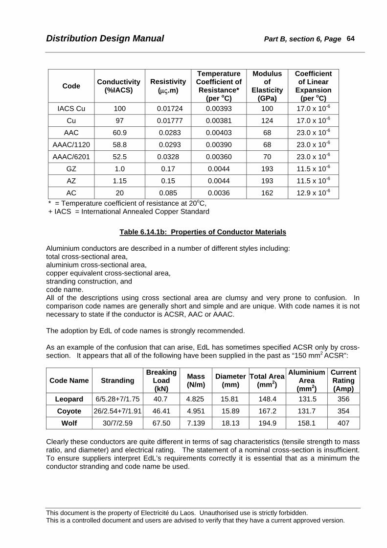
Distribution Design Manual Part B, section 6, Page
This document is the property of Electricité du Laos. Unauthorised use is strictly forbidden. This is a controlled document and users are advised to verify that they have a current approved version.
64
Code Conductivity (%IACS)
Resistivity (μς.m)
Temperature Coefficient of Resistance*
(per oC)
Modulus of
Elasticity (GPa)
Coefficient of Linear
Expansion (per oC)
IACS Cu 100 0.01724 0.00393 100 17.0 x 10⁻⁶
Cu 97 0.01777 0.00381 124 17.0 x 10⁻⁶
AAC 60.9 0.0283 0.00403 68 23.0 x 10⁻⁶
AAAC/1120 58.8 0.0293 0.00390 68 23.0 x 10⁻⁶
AAAC/6201 52.5 0.0328 0.00360 70 23.0 x 10⁻⁶
GZ 1.0 0.17 0.0044 193 11.5 x 10⁻⁶
AZ 1.15 0.15 0.0044 193 11.5 x 10⁻⁶
AC 20 0.085 0.0036 162 12.9 x 10⁻⁶ * = Temperature coefficient of resistance at 20oC, + IACS = International Annealed Copper Standard
Table 6.14.1b: Properties of Conductor Materials
Aluminium conductors are described in a number of different styles including: total cross-sectional area, aluminium cross-sectional area, copper equivalent cross-sectional area, stranding construction, and code name. All of the descriptions using cross sectional area are clumsy and very prone to confusion. In comparison code names are generally short and simple and are unique. With code names it is not necessary to state if the conductor is ACSR, AAC or AAAC. The adoption by EdL of code names is strongly recommended. As an example of the confusion that can arise, EdL has sometimes specified ACSR only by cross-section. It appears that all of the following have been supplied in the past as “150 mm2 ACSR”:
Code Name Stranding Breaking
Load (kN)
Mass (N/m)
Diameter (mm)
Total Area (mm2)
Aluminium Area
(mm2)
Current Rating (Amp)
Leopard 6/5.28+7/1.75 40.7 4.825 15.81 148.4 131.5 356
Coyote 26/2.54+7/1.91 46.41 4.951 15.89 167.2 131.7 354
Wolf 30/7/2.59 67.50 7.139 18.13 194.9 158.1 407 Clearly these conductors are quite different in terms of sag characteristics (tensile strength to mass ratio, and diameter) and electrical rating. The statement of a nominal cross-section is insufficient. To ensure suppliers interpret EdL’s requirements correctly it is essential that as a minimum the conductor stranding and code name be used.

Distribution Design Manual Part B, section 6, Page
This document is the property of Electricité du Laos. Unauthorised use is strictly forbidden. This is a controlled document and users are advised to verify that they have a current approved version.
65
6.14.2 Conductor temperature The maximum operating temperature of an overhead conductor is determined by:
• Current loading • Climatic conditions (solar gain, wind cooling) • Permissible temperature rating of any covering • Satisfactory clearances to ground and structures.
The thermal limit is controlled by the permanent loss of tensile strength (annealing). The recommended maximum temperature limit for normal operation of AAC, AAAC, and ACSR is 100oC. After 1000hours at 100oC there is an approximate loss of strength of 3%. At higher temperatures the loss of strength is more rapid.
6.14.3 Current rating The maximum normal current rating of an overhead conductor is a function of the maximum permissible temperature and allowable temperature rise. In recognition of the design ambient temperature of 45oC, a maximum permissible temperature of 75oC is chosen (ie. allowable temperature rise 30oC). At distribution voltages, volt drop usually dictates the required conductor cross-section. Selection of 75oC provides a margin for abnormal conditions before the thermal limit is reached. For clearances above ground, 75oC still air conditions are assumed. A very small air movement from wind has a significant effect on the current carrying rating of an overhead conductor. The current rating of a bare overhead conductor is given by:
RcPsPrPfI −+
=
where: Pf is the convection loss Pr is the radiation loss Ps is the solar gain, and Rc is conductor resistance.
These terms are complex. A detailed explanation is shown in Appendix B6.9 including a typical calculation sheet. The current rating of a conductor is determined from:
• Permissible temperature rise (based on maximum temperature and ambient) • Heat dissipation by wind • Solar input, radiation gain/loss • Conductor resistance.
Therefore a circuit will have different ratings depending upon time of day, and if there is a wind.
The current ratings of conductors used on the EdL distribution network are shown in section 8.
6.14.4 Fault rating For overhead conductors the main factors to consider are:
• Annealing of the conductor from heating due to magnitude and duration of fault current, • Sagging of the conductor into another below it, • Reduced clearances to ground and structures, • Conductor movement due to electromagnetic forces that may result in flashover, arc
damage, and clashing.

Distribution Design Manual Part B, section 6, Page
This document is the property of Electricité du Laos. Unauthorised use is strictly forbidden. This is a controlled document and users are advised to verify that they have a current approved version.
66
Fault conditions are of short duration from a few cycles to about 1.0 second and it is usual to assume no natural heat dissipation or cooling (adiabatic conditions). To avoid excessive loss of tensile strength the final temperature of the conductor after allowing for the cumulative effect of reclosing should not exceed the values shown in Table 6.14.4. This data taken from HB C(b)1-199937, is for up to 5% loss of conductor tensile strength.
Conductor type Approximate cross-section
(mm2)
Maximum temperature
Hard drawn copper 60 200oC AAC, AAAC/1120, ACSR/GZ 100 160oC
ACSR/AZ, ACSR/AC 300 to 500 150oC
SC/AC 400oC
Table 6.14.4: Guidelines for 5% loss of tensile strength for total fault clearing time Methods for calculation of temperature rise under fault conditions are shown in HB C(b)1–1999. A typical calculation sheet is shown in Appendix B6.10. The 1-second fault current ratings of conductors used on the EdL distribution network are shown in section 8. One second is selected to minimise the risk from annealing. The burn down time for conductors is much longer. Changes of conductor sag under fault conditions or during periods of sustained operation at elevated temperature can be calculated by the methods demonstrated in Electricity Supply Association of Australia publication “Current Rating of Bare Overhead Line Conductors”38, and other standard texts The movement of conductors under fault conditions is complex. The subject is referred to in C(b)1 - 1999. Excessively slack conductors erected to low stringing tensions will move more under heavy fault currents than adequately tensioned conductors. Conductors used for earthing are usually attached to a surface or direct buried so loss of tensile strength is of less importance. It is normal practice to allocate a 3-second rating and the melting temperature for earthing conductors. This time allows for back-up protection to operate and is consistent with switchgear fault rating.
6.14.5 Conductor tensions The limiting conditions for conductor tensions may be governed by either the Ultimate Strength Limit State or the Serviceability Limit State as discussed in Part A. Fatigue failures of overhead line conductors usually occur where the conductor is secured to fittings. The cause of such failures is dynamic stress induced by vibration combined with high static stresses. This subject is discussed more fully in reference HB C(b)1–1999. To avoid problems from vibration induced fatigue failure it is recommended that the Everyday Tension of conductors (Serviceability State conditions) not exceed the values shown in Table 6.14.5. The
37 “Guidelines for Design and Maintenance of Overhead Distribution and Transmission Lines”, C(b)1-1999, Electricity Supply Association of Australia. 38 D(b)5 – 1988.

Distribution Design Manual Part B, section 6, Page
This document is the property of Electricité du Laos. Unauthorised use is strictly forbidden. This is a controlled document and users are advised to verify that they have a current approved version.
67
tensions listed are the percentage of breaking load after allowing for strand settlement and metallurgical creep. Data for fully damped conductors has been omitted, as vibration dampers are not normally used at distribution voltages. For the purposes of this guideline tangential tension may be regarded as equivalent to horizontal conductor tension. The temperature selected at which the Everyday Tension is customarily set as the mean temperature for the coldest month of the year39. In Lao PDR the coldest month mean temperature varies from approximately 15oC in northern provinces to approximately 25oC in southern provinces. A single value is preferred to avoid confusion. 20oC has been selected as a practical compromise and is associated with a conservative value (18%) for the percentage of ultimate strength. In most circumstances on distribution construction the governing criteria for conductor tension will be the Serviceability Limit State, with the possible exception of very small conductors where Ultimate Limit State may be the ruling condition. Where these rules are adopted particular care must be taken during conductor erection that the correct initial tensions are not exceeded. Horizontal Tension (% BL)
Recommended Incremental Increase
Static Stress Considerations
Dynamic Stress Considerations
Clamp Category * Terrain Category #
Conductor Type
Base Case
A B C 1 2 3
Recommended Maximum
Tension (% BL)
Copper 25.0 0 1.5 2.5 0 2.0 4.0 34.0
SC/GZ, SC/AC 10.0 0 2.5 5.0 0 5.0 10.0 31.0
AAC 18.0 0 1.5 2.5 0 2.0 4.0 27.0
ACSR 3/4, 4/3 10.0 0 2.0 4.0 0 4.0 8.0 27.0
ACSR 6/1, 6/7 17.0 0 1.5 2.5 0 2.0 4.0 27.0
ACSR 30/7 16.0 0 1.5 2.5 0 2.0 4.0 25.0
LVABC N/A N/A N/A N/A N/A N/A 28.0
* Clamp Category: Type A Post or pin insulator with ties (no armour guards). Type B Post or pin insulator with armour guards. Type C Helical ties with armour guards. # Terrain Category: Type 1 Flat, no obstacles Type 2 Rolling terrain with scattered trees Type 3 Mountain, Forest, or Urban
Table 6.14.5: Conductor Everyday Load Horizontal Tension
39 As recommended in “Guidelines for Design and Maintenance off Overhead Distribution and Transmission Lines”, C(b)1-1999, Electricity Supply Association of Australia.

Distribution Design Manual Part B, section 6, Page
This document is the property of Electricité du Laos. Unauthorised use is strictly forbidden. This is a controlled document and users are advised to verify that they have a current approved version.
68
In accordance with customary international practice EdL does not use armour rods or line guards on overhead distribution lines, so Clamp Category A is applicable. In Laos PDR the most prevalent terrain is Category 2. Maximum everyday tension applicable for EdL are therefore:
• Hard drawn copper 27% ultimate • SC/AC 15% ultimate • 6/1 and 6/7 ACSR 19% ultimate (18% used for consistency with 30/7 ACSR) • 30/7 ACSR 18% ultimate
6.14.6 EdL Standard Conductors Recent major distribution expansion projects undertaken by EdL (including Southern Provinces Electrification, VPRE, PGI) have generally used conductors based on British Standard strandings and dimensions. Earlier projects used German (DIN) sizes. Other Standards have also been used generally reflecting the origin of project funding or the project consultant. Standard MV conductors used by EdL are:
Aster 288mm2, 37/3.15AAAC (288mm2 aluminium area) WOLF, 30/7/2.59ACSR (158mm2 aluminium area) 70mm2, 19/2.10 AAAC (65mm2 aluminium area) MINK, 6/1/3.66ACSR (63mm2 aluminium area) WEASEL, 6/1/2.59ACSR (31mm2 aluminium area) 3/2.75 SC/AC (for use on SWER lines)
The standard LV conductors used by EdL are:
3 x 150/70 LVABC (150/70mm2 aluminium area) 4 x 70 LVABC (70mm2 aluminium area) FLY 7/3.40AAC PVC and bare (63mm2 aluminium area) MOSQUITO 7/2.59AAC PVC and bare (36mm2 aluminium area)
The introduction of 4 x 95 LVABC should be considered. This will reduce voltage drop and/or permit longer lengths for LV distributors. Conductors used for consumer service connections are:
4 x 35mm2 LVABC 4 x 25mm2 LVABC 2 x 25mm2 LVABC 1 x 10mm2 (7/1.35) Cu XLPE
The preferred sizes are shown in bold type. A number of other conductors of similar cross-section have previously been used. The above conductors provide a rational and adequate range for normal applications40. A limited number and type of conductors simplifies selection, reduces the range of accessories, and affords economies for purchase and Stores holding. Alternative and additional conductors should not be introduced without extensive engineering analysis. Physical and electrical characteristics of the commonly used conductors are detailed in Appendix B6.7. With the exception of the recently introduced LVABC most conductor sizes and stranding are in accordance with BS215, although usually purchased with material properties and manufacturing details defined according to IEC Standards. 40 There is a possible application for a LV conductor of 95 to 120mm2 aluminium cross section, either single wire or LVABC.

Distribution Design Manual Part B, section 6, Page
This document is the property of Electricité du Laos. Unauthorised use is strictly forbidden. This is a controlled document and users are advised to verify that they have a current approved version.
69
6.15 Overhead Conductor Mechanical Loading
6.15.1 Sag and tension Conductor sag and tension analysis is an important consideration in overhead distribution line design. For economic line design conductor sags should be kept to minimum to save on extra pole height. Tension contributes to the transverse (sideways) loading on angle and termination poles and excessive tensions may overload the conductor. On distribution construction small conductors (eg. Weasel, Mosquito) can generally be erected to utilise their full strength. Because of additional guying loads and practical construction considerations it is generally not economic to erect larger conductors (eg. Wolf) to utilise their full strength For the calculation of sags and tensions in the conductors of overhead lines conductor weight (mass), elasticity, wind pressure, temperature, and creep are the dominant factors. A flexible inelastic conductor of uniform mass (w) per unit of arc length suspended between two supports takes up the shape of a catenary for which the general equation is:
⎟⎟⎠
⎞⎜⎜⎝
⎛−⎟
⎠⎞
⎜⎝⎛= 1cosh
CxCy where the catenary constant ⎟
⎠⎞
⎜⎝⎛=
wHC
and H = horizontal component of tension
In a level span of length L (supports at the same height) the mid-span sag is;
⎟⎟⎠
⎞⎜⎜⎝
⎛−⎟
⎠⎞
⎜⎝⎛= 1
2cosh
CLCd
A practical approximation of the catenary is the parabola, which is based upon a uniform mass (w) per horizontal unit length. The equation of the parabola is:
Cxy2
2
= and the mid-span sag is H
wLd8
2
=
When the sag is small compared to the span length (less than 6%), the sag calculated by the parabolic method is approximately 0.5 percent smaller than the true catenary sag. For distribution line construction the difference in sag between the two methods can be ignored. An overhead conductor when erected between pole supports will be subjected to:
• tension changes due to wind pressure • temperature changes due to changes in ambient • temperature changes due to heating from current in the conductor • temperature changes due to solar heating and wind cooling • changes in length due to internal metallurgical and settlement effects (creep).
Changes in temperature, applied load (eg. wind), and creep influence the tension and therefore the sag in a span of conductor that must be allowed for to ensure that minimum safety clearances are complied with at all times. It can be shown that the following cubic equation based on the parabola is a satisfactory approximation to the behaviour of overhead conductors particularly for tensions and sags commonly used on distribution construction.41 41 ESAA publication HB C(b)1 discusses the derivation of these formulae, as do many standard texts.

Distribution Design Manual Part B, section 6, Page
This document is the property of Electricité du Laos. Unauthorised use is strictly forbidden. This is a controlled document and users are advised to verify that they have a current approved version.
70
( ) 0LCTLCCTT 23
22
2211
32 =−−−−
where: T1 = initial conductor tension T2 = final conductor tension C1 = (area x modulus x expansion coefficient x (initial temp. – final temp.)) C2 = (area x modulus x (initial weight)2 ) / (24 x (T1)2) C3 = (area x modulus x (loaded weight)2 ) / 24 L = span length With the use of computers the catenary can also be readily solved.
6.15.2 Design wind loads Maximum winds of 40metre/sec (144km per hour) have been recorded in Lao PDR. It is understood that these are from storm events and very localised. It is considered uneconomic for EdL to design and construct the Distribution network for such extreme winds. It is cost effective to adopt a lesser maximum design wind of nominal 100km per hour (approx. 27.5metre/sec)42 and accept the risk of some limited localised damage to supports or fittings in the event of more extreme conditions. Mean wind velocities are less than 2.0m/sec, which is consistent with the condition of lines, standard of construction of lines and buildings, vegetation, etc. observed in Laos PDR. Based on the expressions developed in Part A, the dynamic wind pressure on a conductor is given by:
qz = γw 0.6 Vz2 (Pa)
where γw is the line reliability factor.
For 27.5m/s wind,
qz = 1.0 x 0.6 x 27.52 = 454Pa
For safety clearances to buildings, trees and other obstructions it is usual to calculate side swing at a reduced wind pressure at everyday temperature. Values of 100Pa and 25oC shall be used43. The following wind pressures shall be used:
Maximum design wind pressure 450Pa Reduced wind pressure for side swing clearances 100Pa
(NB. These are Ultimate Limit State wind pressures)
42 Wind speed of 100km/hr is consistent with the published “EdL Regulations for Erection and Operation of Electrical Networks”, May 1991, prepared by Electricité de France International for the EdL Standardisation Group. 43 Value chosen from a recommendation in “Guidelines for Design and Maintenance off Overhead Distribution and Transmission Lines”, C(b)1-1999, Electricity Supply Association of Australia.

Distribution Design Manual Part B, section 6, Page
This document is the property of Electricité du Laos. Unauthorised use is strictly forbidden. This is a controlled document and users are advised to verify that they have a current approved version.
71
6.15.3 Conductor loading conditions Based on the foregoing environmental (temperature) data and design wind conditions, for the calculation of conductor sags and tensions the following shall be used for AAC, and ACSR:
Maximum ambient, still air 45oC Maximum conductor temperature, still air 75oC (ie. conductor temperature rise 30oC) Everyday temperature (EDT), still air 20oC EDT conductor tension not to exceed 18% of ultimate strength Minimum ambient, still air 0oC Maximum conductor tension not to exceed 70% of ultimate strength Maximum wind pressure 450Pa Temperature for maximum wind44 15oC Maximum conductor tension not to exceed 70% of ultimate strength Side swing clearance wind pressure 100Pa Temperature for side swing clearance 25oC
For LVABC the same wind and temperature conditions shall be applied, but for practical considerations lower conductor stresses (and therefore lower tensions) are adopted.
44 15oC selected in recognition of cooling effect of wind. The value is conservative.

Distribution Design Manual Part B, section 6, Page
This document is the property of Electricité du Laos. Unauthorised use is strictly forbidden. This is a controlled document and users are advised to verify that they have a current approved version.
72
6.16 Poles
6.16.1 Concrete poles All present day distribution pole construction is with a standardised range of prestressed concrete poles as listed in Table 6.15. The poles have a large number of holes in both transverse and longitudinal faces. Detailed dimensions and constructional features are shown in standard drawings. The ultimate strength of these poles is rather low and significantly limits the maximum spans that can be constructed. It should be noted that the longitudinal strength is similar to the transverse strength. Common practice is to use concrete poles that have longitudinal strength of 25% to 33% of the transverse strength, and thereby achieving a considerable saving in weight and cost. To achieve more economical lines it would be desirable to introduce additional poles to this range each of approximately twice the transverse strength of the present design. A number of manufacturing plants already exist in Lao PDR using moulds for the present design. It is recognised that there is a large capital investment in these plants and so the present pole designs are likely to remain in use for several years. However, this should not preclude the introduction of higher strength poles. Prestressed concrete poles are economical and if manufactured to high quality standards are very durable. A physical life in excess of 50years can be anticipated. Good quality control is essential during manufacture. Important aspects include:
• Moulds maintained true to dimension. • Accurate location of steel, both tension strand and shear reinforcing to ensure adequate
concrete cover. • Consistent quality concrete mix. • Correct and even tensioning of the prestressing strand to ensure the pole is straight. • Smooth and even finish to the concrete surfaces. • Accurate placement of the dowels to ensure holes are perpendicular to the faces. • Controlled curing and de-stressing processes.
Most of these attributes can be assured by close quality control during manufacture and can be proven by regular proof testing of at least 1 pole for every 100 manufactured.
6.16.1.1 Ultimate strength The determination of the ultimate strength of a pole is by type tests to destruction on not less than three poles of each design. The test must include loading in both transverse and longitudinal directions (ie. at least six poles need to be tested to failure). The applied load should be in increments of 5% to 10% of the designed ultimate strength with a careful note made of the deflection at each increment.
6.16.1.2 Routine (proof) testing Proof testing consists of loading sample poles to about normal working load (50% to 60% of ultimate) and comparing deflections of the pole top with the results from the destruction tests. The average of the deflections observed during the destruction tests should be used. Any pole that has deflections at each load increment more than 15% greater than the standard deflections is considered to not pass the proof test, and the batch that it represents should be rejected. The test

Distribution Design Manual Part B, section 6, Page
This document is the property of Electricité du Laos. Unauthorised use is strictly forbidden. This is a controlled document and users are advised to verify that they have a current approved version.
73
is stopped at about the 60% ultimate load and if the results are satisfactory the pole will be undamaged and may be used for normal construction. A more detailed description of the testing procedure is included in various National Standards of which NZS 3115:198045 is an example.
Overall Length 8.0m 10.0m 12.0m 14.0m 16.0m 18.0m
Burial Depth (mm) 1500 1000 2000 2000 2100 2300
Top (width x depth) (mm) 120 x 120 197 x 172 180 x 160 200 x 160 200 x 160 200 x 160
G/L (width x depth) (mm) 193 x 161 263 x 218 263 x 218 290 x 280 358 x 308 374 x 334
Butt (width x depth) (mm) 210 x 170 280 x230 280 x230 305 x 300 370 x330 400 x 360
Ultimate Transverse Strength* (N) 3780 8698 7460 8220 9910 10770
Ultimate Longitudinal Strength* (N) 2840 6524 5595 8030 8595 9460
Approx. Mass (kg) 550 1154 1400 2075 3195 3550
* = load applied 300mm from top of pole.
Table 6.16: Standard Prestressed Concrete Poles
6.16.2 Steel poles There are a variety of steel poles in use on the EdL distribution network. The most common are of a lattice construction and believed to be of European design. No design data is available for these poles. Except for some minor damage to individual members these poles are generally in very good condition and should give many more years of satisfactory service. EdL should endeavour to obtain the full design data so the poles will not be overloaded during system reconstruction and so that replacement members can be fitted when necessary. There are a few examples of tubular section poles, and other types but again no design data is available for them.
6.16.3 Wooden poles Although a few wooden poles remain in service these are being systematically replaced. In a tropical climate wooden poles need to be of very durable species that usually still require preservative treatment and often have significant on-going maintenance needs. In deliberately moving away from the use of wooden poles EdL have consciously avoided many future problems.
45 NZS 3115 :1980 “Concrete Poles for Electrical Transmission and Distribution”

Distribution Design Manual Part B, section 6, Page
This document is the property of Electricité du Laos. Unauthorised use is strictly forbidden. This is a controlled document and users are advised to verify that they have a current approved version.
74
6.17 Crossarms Crossarms are used to support MV and LV insulators, fuse gear, and related equipment on pole structures. Early construction employed galvanised steel angle and channel sections and many crossarms of this type remain in service. In recent years, prestressed concrete crossarm have been widely adopted for MV pole construction. LV crossarms are no longer used as LV conductors are supported by vertical steel racks fixed directly to the pole face. Crossarm braces are fitted on poles to prevent twisting (rotation) of the arm under unbalanced vertical load. Although two braces are used it customary to assume that only the brace loaded in tension resists the unbalance loads.
Figure 6.17: Crossarm Loading Crossarms are subjected to transverse, longitudinal and vertical loads applied from the conductors through the supporting insulators. Other crossarm loads are self-weight and wind although these are usually small compared to the conductor loads. Crossarms with tension insulators must also support the conductor longitudinal loads. Provided the conductors are correctly tensioned during erection longitudinal loads on pin-type crossarms are also small under normal conditions. During

Distribution Design Manual Part B, section 6, Page
This document is the property of Electricité du Laos. Unauthorised use is strictly forbidden. This is a controlled document and users are advised to verify that they have a current approved version.
75
construction and in the event of a broken conductor, crossarms may be subject to abnormal longitudinal and vertical loads although wind loads are usually minor. Typical loading conditions are illustrated in Figure 6.17.
6.17.1 Concrete crossarms EdL uses one standard size of prestressed spun concrete crossarm, 2500 x 100 x 100mm. Dimensions and constructional features are shown in Standard drawings. The number of holes for the attachment of hardware is very limited. This severely restricts the placement of insulators, although other hardware such as MV fuses and surge arresters are usually attached by multi purpose clamping brackets (eg. ANSI pattern). Crossarm strength is detailed in table section 8. In normal service crossarms are subject to vertical load from the weight of the conductors, transverse load from the effect of wind on the conductors, transverse load from the effect of conductor tension at changes in line direction, longitudinal load from unbalanced or termination conductor tensions. The EdL standard 2.5m crossarm has a design ultimate moment of approximately 7800Nm.
6.17.2 Steel crossarms No design or strength data is available for the many steel crossarm types and sizes in use on the EdL distribution network. Section sizes are generally small consistent with the moderate conductor tensions used on most distribution lines. Steel crossarms should continue to be used where increased conductor spacing and/or hardware fixing makes the standard concrete crossarms unsuitable. In the design process attention must be given to unbalance loads, and torsion loads as well as the normal conductor transverse and vertical loads. Galvanised steel in outdoor applications appears to have a very long life in Lao PDR no doubt due to the absence of marine and industrial pollutants. To ensure adequate life in service and avoid unsightly rust staining, painted steel should not be used for crossarms and other pole hardware.
6.17.3 Timber crossarms Because of unsatisfactory service life and warping, EdL no longer uses wooden crossarms. Timber does however offer a number of technical advantages including:
• Enhanced insulation performance against lightning. It is well established that the surge impedance of timber is high and can greatly improve the lightning resistance of distribution lines. While EdL’s service experience with conventional pin insulators has been unsatisfactory because of frequent puncture failures, it is believed the large numbers of still serviceable pin insulators would be useable if erected on timber crossarms.
• Flexibility to modify on site by cutting and drilling to suit particular applications. • Ease of handling and transport.
Where timber is used the species must be chosen carefully for durability and dimensional stability in long-term outdoor exposure. Appropriate preservative treatment may be necessary for the sapwood of some species.
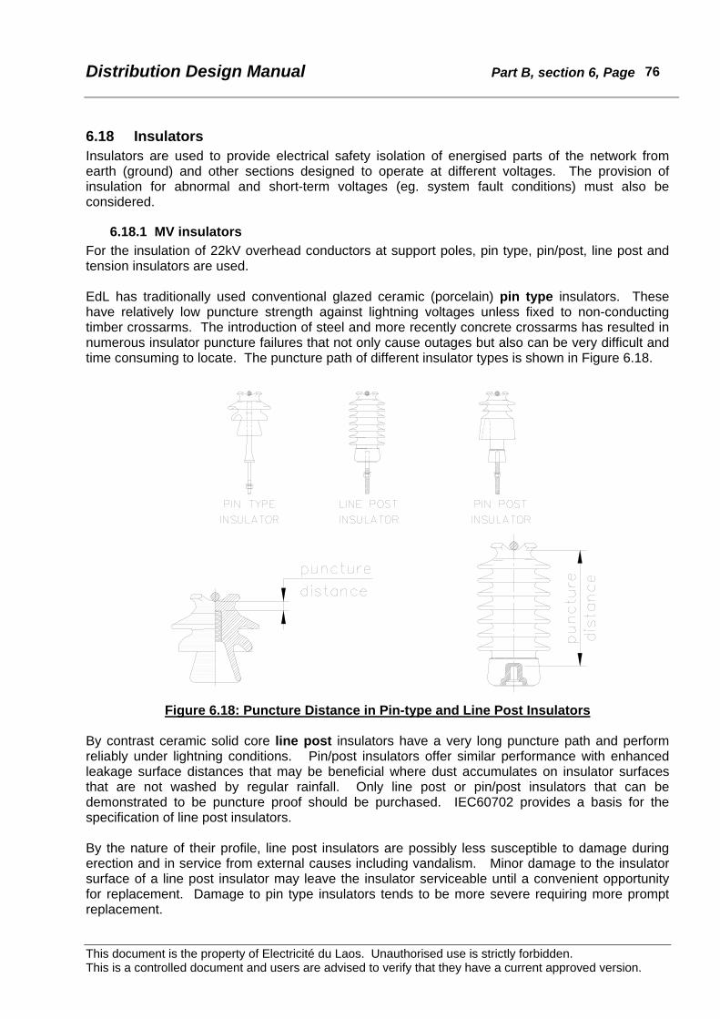
Distribution Design Manual Part B, section 6, Page
This document is the property of Electricité du Laos. Unauthorised use is strictly forbidden. This is a controlled document and users are advised to verify that they have a current approved version.
76
6.18 Insulators Insulators are used to provide electrical safety isolation of energised parts of the network from earth (ground) and other sections designed to operate at different voltages. The provision of insulation for abnormal and short-term voltages (eg. system fault conditions) must also be considered.
6.18.1 MV insulators For the insulation of 22kV overhead conductors at support poles, pin type, pin/post, line post and tension insulators are used. EdL has traditionally used conventional glazed ceramic (porcelain) pin type insulators. These have relatively low puncture strength against lightning voltages unless fixed to non-conducting timber crossarms. The introduction of steel and more recently concrete crossarms has resulted in numerous insulator puncture failures that not only cause outages but also can be very difficult and time consuming to locate. The puncture path of different insulator types is shown in Figure 6.18.
Figure 6.18: Puncture Distance in Pin-type and Line Post Insulators By contrast ceramic solid core line post insulators have a very long puncture path and perform reliably under lightning conditions. Pin/post insulators offer similar performance with enhanced leakage surface distances that may be beneficial where dust accumulates on insulator surfaces that are not washed by regular rainfall. Only line post or pin/post insulators that can be demonstrated to be puncture proof should be purchased. IEC60702 provides a basis for the specification of line post insulators. By the nature of their profile, line post insulators are possibly less susceptible to damage during erection and in service from external causes including vandalism. Minor damage to the insulator surface of a line post insulator may leave the insulator serviceable until a convenient opportunity for replacement. Damage to pin type insulators tends to be more severe requiring more prompt replacement.

Distribution Design Manual Part B, section 6, Page
This document is the property of Electricité du Laos. Unauthorised use is strictly forbidden. This is a controlled document and users are advised to verify that they have a current approved version.
77
Because of the moderate strength poles used by EdL and the low wind pressures adopted for distribution line design, line post (and pin type) insulators of 8kN minimum bending failing load are adequate. Attention must be given to the correct and uniform specification of the dimensions of the tietop head off all post and pin insulators to ensure that helical type ties46 can be satisfactorily used if their use should be warranted in the future. Only line post or pin/post insulators should be purchased in the future. Consideration should be given to the use of redundant but serviceable pin insulators. These could be utilised on minor spur lines where there are spur isolation fuses. Alternatively, pin insulators should give satisfactory service if used on durable timber crossarms. For distribution tension (strain) insulators EdL have traditionally used cap and pin disc type insulators (2 or 3 per string at 22kV) as conventionally used on transmission lines. The electrical performance of these insulators is very satisfactory, but the end fittings require additional coupling hardware components for connection to clevis and tongue fittings at the pole and conductor ends. Ceramic disc insulators are heavy and easily broken. Composite tension and suspension insulators consist of a central insulating core bearing the mechanical load protected by a polymeric housing, with the load transmitted to the core by metal fittings. The central insulating core is commonly resin-impregnated fibreglass or similar material. The weather shield housing may be of a variety of materials including silicone, ethylene-propylene, resins, and fluorocarbons. All of these materials are lightweight and extremely resistant to mechanical damage. For distribution applications clevis and tongue end fittings are normally specified either in aluminium alloy or forged steel. Forged steel fittings provide a higher strength rating that can prevent breakage of the clevis end if mis-used. IEC61109 and IEC61466 describe the testing methods, strength classes, standard end fittings and electrical characteristics for composite insulators. The greatest benefits from the adoption of composite tension insulators are the avoidance of breakages and the reduced weight. Typical weights of the insulators required for 22kV tension assemblies are:
Ceramic disc (3 - 255 x 146): 14.0 to 16.5kg Composite: 1.0 to 1.5kg
Only composite tension insulators should be purchased in the future.
6.18.2 LV insulators The dimensions and electrical specification for outdoor insulators rated less than 1kV are dictated mainly by strength requirements and the size of the conductors and fittings to be attached or supported. EdL uses exclusively vertical rack construction for open wire LV, for which bobbin type insulators are appropriate. Glazed ceramic (porcelain) insulators are the preferred type because of good durability and low cost. Because of the small compact dimensions breakages are generally not a problem. Insulator surfaces and profiles must be smooth and of adequate radius for the conductors and fittings to be supported.
46 “Preformed”, “helitie”, “wraplock” are commonly used industry names for this type of helical fitting that requires no conventional binders.
Distribution Design Manual Part B, section 6, Page
This document is the property of Electricité du Laos. Unauthorised use is strictly forbidden. This is a controlled document and users are advised to verify that they have a current approved version.
78
6.19 Conductor Hardware Hardware fittings for use on aluminium type overhead conductors include:
• bolted strain clamps and helical dead ends, • compression joints, full tension and non-tension, • helical tension joints, • parallel groove connectors, • insulation piercing connectors for tapping from covered and insulated conductors, • helical protection fittings.
Tension fittings must have a holding strength of not less than 85% of the rated conductor breaking load. For all-aluminium and aluminium alloy conductors up to 100% is usually achieved. The conductivity of all joints and connectors must be not less than the current rating of the conductor.
6.19.1 Helical full tension joints Helical tension joints comprise sets of helically formed wires of material compatible with the conductor that are applied by hand to form a joint. No tools are required for installation. The holding strength is commonly in excess of the conductor breaking load, and joint conductivity can be better than the conductor. These helical fittings or a shortened version known as patch rods or line splices can be used to repair strand damage to a conductor.
6.19.2 Helical dead-end fittings Helical dead-end fittings can be purchased for most types of conductors (copper, AAC, AAAC, ACSR, galvanised steel, aluminium–clad steel, etc), and also for covered and insulated conductors. These fittings are simple to apply, require no tools, and can be readily loosened during installation to adjust conductor sag. The holding strength is commonly in excess of the conductor breaking load. Care must be taken to select the correct fitting for the particular conductor material and diameter. The eye loop usually requires a purpose made fitting of adequate radius, but these are simple and inexpensive. The conductor tail is usually taken through the dead-end without the need for a connector on the tensioned section of the conductor. Helical dead-end fittings are in general use on steel guywires. By comparison bolted type strain clamps and compression dead-end fittings are more difficult to apply, do not allow for adjustment of the clamp position once applied, and require tools for installation.
6.19.3 Compression joints Compression joints, both full tension for use in the span and non-tension for use on jumpers, comprise a sleeve of material compatible with the conductor which is pressed on to the conductor with an hydraulic tool. The holding strength of compression joints can be matched to the conductor breaking load. Care must be taken to select a joint (sleeve) of the correct diameter, use the correct dies, and fully compress the fitting.
Distribution Design Manual Part B, section 6, Page
This document is the property of Electricité du Laos. Unauthorised use is strictly forbidden. This is a controlled document and users are advised to verify that they have a current approved version.
79
6.19.4 Parallel groove connectors Parallel groove clamps are a bolted fitting made of material compatible with the conductors. Correctly designed and properly applied they can provide satisfactory service. Clamps can have a current rating comparable with the conductor. Care must be taken to thoroughly clean the conductor surfaces before application and use oxidation inhibiting joint compound. Failure do to so can result in joint failure often after the passage of fault current. Care must also be taken to correctly tighten the bolts on the fittings. Parallel groove clamps have the advantage that they can be readily removed and are therefore convenient for temporary connections.
6.19.5 Insulation piercing connectors An insulation piercing connector (IPC) is a fully insulated tapping and jointing connector for use on PVC and XLPE insulated and covered overhead conductors. Connectors are suitable for both copper and aluminium insulated conductors. IPC’s are fully insulated and suitable for safe installation on live cables. The connectors have conducting teeth that penetrate the insulation through to the conductor when the clamping bolt is sufficiently tightened. The clamping pressure is controlled by a shear-head or similar arrangement on the bolt. Clamping bolts are insulated from the conductors. The connectors are completely sealed and water tight to a 6kV insulation test. IPC’s were developed for use on LVABC but can be used on other insulated and covered conductors. A similar pattern of connector is also available for tapping insulated conductors from bare aluminium and copper overhead conductors. These employ grooved connector plates rather than teeth for the contact to the bare conductor. Features of IPC’s that contribute to performance include:
• Quick and simple installation without need to strip or cut insulation • Can be safely applied to live cables • Durable ultra-violet resistant insulated body • Shear-head bolt for correct torque control requires only simple open-end spanner • Grease filled to prevent corrosion of aluminium conductor • End cap to seal cut end of branch (tap) cable
Like conventional parallel groove clamps IPC’s have a range of conductor diameters to which they can be applied. Many sizes are available, but if care is taken in selection only a small number of stock items need be kept. Tables 6.19.5a and 6.19.5b list a practical range of IPC’s for tapping conductors from 6mm2 upwards and main (run) conductors from 16mm2 upwards. It should be noted that at a major branch it is often necessary to tap off a conductor the same size as the main. IPC’s for fitting to bare conductors must have the bridge and contact surface material compatible with the bare conductor, so different connectors are required for bare copper, and bare aluminium/aluminium alloy. On these fittings the tap conductor side has insulation piercing contacts. IPC’s can be removed from a conductor after the shear head has been broken, but the connectors are not suitable for re-use. If removed from LVABC the puncture damage to the insulation must be made good by suitable taping to prevent the ingress of water.

Distribution Design Manual Part B, section 6, Page
This document is the property of Electricité du Laos. Unauthorised use is strictly forbidden. This is a controlled document and users are advised to verify that they have a current approved version.
80
Main (mm2) Cu or AL
Tap (mm2) Cu or AL
Max Current (Amp) Bolts
Application
16 - 70 4 - 35 200 1 x M8 Service connection
35 - 95 25 - 95 375 1 x M8 Main - main
50 - 150 4 - 35 200 1 x M8 Service connection
50 - 150 35 - 95 375 1 x M8 Main - main
50 - 150 50 - 150 500 2 x M10 Main - main
Table 6.19.5a: IPC Connector Selection – Insulated Main and Tap-off
Bare Main (mm2)
Cu AL
Tap (mm2)
Cu or AL Max Current
(Amp) Bolts
Application
16 - 70 16 - 50 4 - 35 200 1 x M8 Service connection
16 - 95 16 - 95 35 - 95 375 2 x M8 Main - main
50 - 150 50 - 150 6 - 35 200 1 x M8 Service connection
50 - 150 50 - 150 35 - 95 375 2 x M8 Main - main
50 - 150 50 - 150 50 - 150 500 2 x M10 Main - main
Table 6.19.5b: IPC Connector Selection – Bare Main and Insulated Tap-off

Distribution Design Manual Part B, section 6, Page
This document is the property of Electricité du Laos. Unauthorised use is strictly forbidden. This is a controlled document and users are advised to verify that they have a current approved version.
81
6.20 Other Hardware Other pole hardware including bolts, crossarm braces, cabinets, mounting brackets, cable mechanical protection covers, etc., must be durable, resistant to corrosion, resistant to ultra-violet, and generally provide a long service life. All ferrous parts should be generously dimensioned and must be hot dip galvanised. Bolts are generally metric M16 hexagon as a minimum to ensure robustness and ease of installation with standard tools. Cabinets should be of fully galvanised steel or aluminium alloy construction with robust doors and mounting arrangements. All internal equipment should be at least partially weatherproof in case rain enters the cabinets. All accessible components must be fully insulated and adequately protected against accidental contact. Robust and durable materials must be used throughout. Internal construction and dimensions must be appropriate for the overall size of cables likely to be terminated and terminals readily accessible for installation. Cables fitted to poles must be fully insulated sheathed or screened type. Large diameter cables are difficult to handle and cannot be shaped to sharp bends. Where practicable cable should be single core PVC or XLPE insulated and sheathed. Copper cable will usually have a smaller diameter than aluminium for the equivalent current rating making handling and installation easier. Copper cables are usually cheaper to connect to terminals (eg. transformer bushings) because expensive bimetal connectors can be avoided. Savings in connector and installation costs justify the higher cost of copper cable over short lengths such as at transformer structures or metering installations. Cable protection covers, conduit, and pipe should not be PVC as this is not ultra-violet resistant and becomes brittle. PVC does not readily withstand impact loading. For this type of application black polyethylene pipe is recommended. This material is tough, withstands impact and can be shaped although only to quite large radii. It is particularly suitable for protection earthwires that are taken down the pole to buried electrodes (earth rods). Clips, saddles and banding for fixing cables in position must be durable and should be generously dimensioned. Near ground level these items are subject to unauthorised interference and higher on pole structures secure fixing will enhance appearance and serviceability.
Distribution Design Manual Part B, section 6, Page
This document is the property of Electricité du Laos. Unauthorised use is strictly forbidden. This is a controlled document and users are advised to verify that they have a current approved version.
82
6.21 Distribution Transformers
6.21.1 Transformer specification Standard transformer ratings are listed in section 8. Three phase transformers shall be vector group Dyn11. All transformers shall have the primary winding equipped with a five position off-load tapping switch for input voltages -5%, -2.5%, normal, +2.5% and +5% of nominal 22kV (or 12.7kV in the case of SWER distribution units). The secondary voltage of three phase transformers shall be 400/230volt, and for single phase and SWER transformers shall be 230-0-230volt. The secondary voltage is chosen so as to afford a standard 220volt ±6% supply after allowing for transformer regulation and LV Distributor volt drop. Consideration shall be given to a change to 415/240volt and 240-0-240volt secondary voltages at an appropriate future time. All transformers up to and including 400kVA shall be suitable for platform mounting on 2-pole structures. Transformers up to and including 50kVA shall also be supplied with brackets or fittings to allow single pole mounting. Transformers 500kVA and larger shall be arranged for pad mounting at ground level. All transformers shall be fitted with outdoor bushings for the MV winding. The “earth” end of SWER windings shall be brought out on a nominal LV rated insulated bushing. Suitable brackets for the mounting of surge arresters shall be fitted adjacent to the 22kV bushings on all transformers.47 All LV bushings shall be rated for outdoor use. On single phase and SWER transformers four LV bushings shall be fitted and supplied with external links to provide either a three-wire 230-0-230volt supply or a 230volt 2-wire supply. All transformers shall be hermetically sealed.
6.21.2 Transformer selection The critical factor in determining the allowable load on any transformer is the maximum value of the hottest point or region in the winding so as the insulation materials are not damaged. For oil filled transformers with solid insulation in accordance with IEC6007648, the allowable top-oil temperature rise is 60oC based on a maximum ambient temperature of 40oC. These correspond to a hot spot temperature of 105oC. For air-cooled transformers the normal ambient is required to be between -25oC and +40oC subject to the temperature at the installation site not exceeding:
• +30oC monthly average in the hottest month, and
• +20oC yearly average.
The thermal time constant of a power transformer is relatively long49 and it will be undamaged by short periods of overloading provided:
• the loading before the peak load was less than the rated load, • the duration of the overload is short, and • load is reduced to less than rated load immediately after the overload period.
47 This will simplify the installation of arresters on the transformer tank when necessary. 48 IEC60076 Power transformers. 49 Larger units will have a longer time-constant. See IEC60076.

Distribution Design Manual Part B, section 6, Page
This document is the property of Electricité du Laos. Unauthorised use is strictly forbidden. This is a controlled document and users are advised to verify that they have a current approved version.
83
Methods of determining the permissible loading for oil-filled transformer subject to cyclic loading are given in IEC60354.50 Transformer kVA rating should be matched to the expected maximum half-hour load. Typical distribution transformers on the EdL network have a pronounced short duration peak load in the early evening with relatively low load at other times. The Asian Development Bank has recommended an average transformer utilisation factor of 60% for the EdL distribution network51. This is a challenging target, as transformer utilisation factors of 40% to 50% are more usual. At the time of installation the rating of a distribution transformer should be between 60% and 80% of the expected peak load within two to three years. Transformers of excessive capacity represent the uneconomic use of scarce capital funds, and the continuous iron losses will be greater than warranted by the connected load. Pole mounted transformers can be readily changed as load growth occurs, or additional transformers can be inserted into existing LV networks. Transformer rating should be matched to the known after diversity maximum demand (ADMD), or the future expected ADMD no more than 3 years ahead.
50 IEC60354 loading guide for oil-immersed power transformers. 51 ADB Report RRP:LAO 29273, Proposed loan for Power Transmission and Distribution Project (subsequently ADB n0.1558-LAO SF).

Distribution Design Manual Part B, section 6, Page
This document is the property of Electricité du Laos. Unauthorised use is strictly forbidden. This is a controlled document and users are advised to verify that they have a current approved version.
84
6.22 Transformer LV Cables Insulated cables are installed from transformer LV bushing terminals to LV cabinets and from the cabinet to each outgoing LV distributor. Derating factors must be applied to all cables for the prevailing ambient and environmental exposure. Where there is a LV cabinet (or a single supply to a consumer) only one LV cable circuit is required although this may comprise a number of cables connected in parallel to achieve the required current rating. The transformer cable circuit must be selected to match the transformer rating. Cables for the LV distributors should be rated to the maximum expected load on each distributor. Where several outgoing circuits are connected directly to the transformer LV bushings each circuit must be rated for the expected circuit load. The rating applicable to the cable circuit is dependent upon insulation material, cable type, degree of enclosure, and spacing from surfaces. On pole transformer structures and at some ground mounted installations it is usually necessary to bend the LV cable and attach it to various surfaces. International standards and codes define the rating factors applicable to common installation conditions. A typical document is AS 3008.1-198952. LV cables associated with outdoor transformers can be considered as “bunched in air”, “unenclosed”, and “spaced from surface” all as defined in AS 3008.1. Where transformer cables are installed in conduit or ducts above ground the ducts are usually short and will not significantly affect the current rating of the cable, particularly with regard to other derating factors. Copper and aluminium conductors with PVC and XLPE insulation are suitable for transformer LV cables. The cable type selected should be considered specifically for each transformer rating and the installation conditions. A limited range of cables should be chosen as standard.
6.22.1 Derating factors Where two or more cables or cores of a circuit are connected in parallel a derating factor must be applied to allow for unequal sharing of the currents. Applicable derating factors from table 20 of AS 3008.1 are: No. of circuits 1 2 3 4 Factor 1.00 0.87 0.75 0.72 Where a cable circuit is exposed to direct sunlight the solar heating effect can be allowed for by use of a correction factor corresponding to a temperature higher than the ambient. The current ratings in AS3008.1 are based upon a 40oC ambient, and an allowance of +10oC is considered appropriate for conditions at transformer installations in Lao PDR. The 10oC allowance taken from table 25.1 of AS3008.1 is 0.88.
6.22.2 LV cable bending limits To avoid damage to the insulation and sheaths cables must not installed with excessively sharp bends. Manufacturers publish data on the minimum bending radius for different cable types and voltages. On typical outdoor transformer structures bending radii of the order 400mm are necessary for smaller cables, but larger cables need to be limited to 600mm. Minimum bending radii generally applicable to LV cables and the resulting maximum permissible cable diameters are shown in table 6.21.2a.
52 AS 3008.1-1989, Selection of Cables for Alternating Voltages up to 0.6/1kV.
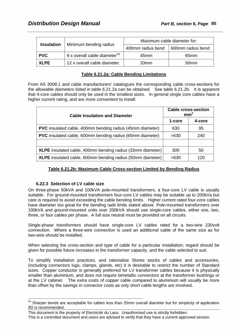
Distribution Design Manual Part B, section 6, Page
This document is the property of Electricité du Laos. Unauthorised use is strictly forbidden. This is a controlled document and users are advised to verify that they have a current approved version.
85
Maximum cable diameter for: Insulation Minimum bending radius
400mm radius bend 600mm radius bend
PVC 9 x overall cable diameter53 45mm 65mm
XLPE 12 x overall cable diameter. 33mm 50mm
Table 6.21.2a: Cable Bending Limitations From AS 3008.1 and cable manufacturers' catalogues the corresponding cable cross-sections for the allowable diameters listed in table 6.21.2a can be obtained. See table 6.21.2b. It is apparent that 4-core cables should only be used in the smallest sizes. In general single core cables have a higher current rating, and are more convenient to install.
Cable cross-section mm2 Cable Insulation and Diameter
1-core 4-core PVC insulated cable, 400mm bending radius (45mm diameter) 630 95
PVC insulated cable, 600mm bending radius (65mm diameter) >630 240
XLPE insulated cable, 400mm bending radius (33mm diameter) 300 50
XLPE insulated cable, 600mm bending radius (50mm diameter) >630 120
Table 6.21.2b: Maximum Cable Cross-section Limited by Bending Radius
6.22.3 Selection of LV cable size On three-phase 50kVA and 100kVA pole-mounted transformers, a four-core LV cable is usually suitable. For ground-mounted transformers four-core LV cables may be suitable up to 200kVa but care is required to avoid exceeding the cable bending limits. Higher current rated four-core cables have diameter too great for the bending radii limits stated above. Pole-mounted transformers over 100kVA and ground-mounted units over 200kVA should use single-core cables, either one, two, three, or four cables per phase. A full size neutral must be provided on all circuits. Single-phase transformers should have single-core LV cables rated for a two-wire 230volt connection. Where a three-wire connection is used an additional cable of the same size as for two-wire should be installed. When selecting the cross-section and type of cable for a particular installation, regard should be given for possible future increases in the transformer capacity, and the cable selected to suit. To simplify installation practices, and rationalise Stores stocks of cables and accessories, (including connectors lugs, clamps, glands, etc) it is desirable to restrict the number of Standard sizes. Copper conductor is generally preferred for LV transformer cables because it is physically smaller than aluminium, and does not require bimetallic connectors at the transformer bushings or at the LV cabinet. The extra costs of copper cable compared to aluminium will usually be more than offset by the savings in connector costs as only short cable lengths are involved.
53 Sharper bends are acceptable for cables less than 25mm overall diameter but for simplicity of application 9D is recommended.

Distribution Design Manual Part B, section 6, Page
This document is the property of Electricité du Laos. Unauthorised use is strictly forbidden. This is a controlled document and users are advised to verify that they have a current approved version.
86
The recommended cross-sections for single-core and 4-core copper cables, PVC insulated and XLPE insulated are 35mm2, 70mm2, 150mm2, 300mm2, and 630mm2. These sizes have been selected based on practically useful values of current rating and 50% to 60% increments in rating between sizes. The use of XLPE gives a higher current rating for similar physical dimensions. If aluminium cables are required the recommended cross-sections sections for single-core and 4-core, PVC insulated and XLPE insulated cables are 50mm2, 95mm2, 185mm2, and 400mm2. Again, these sizes have been selected based on practically useful values of current rating and 50% to 60% increments in rating between sizes. The use of XLPE gives a higher current rating for similar physical dimensions. The current ratings of LV cables suitable for use on transformer installations are shown in Appendix B6.20. These incorporate the relevant derating factors listed above. Copper conductors and XLPE insulation should be selected for circuit ratings greater than approximately 160amp. Tables 6.21.3a and 6.21.3b show the required size of LV cables for standard transformer ratings. Preferred cable cross-sections are marked bold. For single core cables the required size for one, two, three or four cores in parallel is shown. Selection should be based on Standard sizes, material cost (including connectors), and ease of installation. The sizes shown are the minimum that may be used where available otherwise the next largest standard size should be selected. The tables assume bending radius for cables not less than 400mm - larger cables where the bending radius must be not less than 600mm are shown in brackets thus (2 x 400). Because the determination of the conditions for the derating factors is not precise, and as an allowance for cyclic loading, the selection of cable cross-section permits some small overloading of the order of 3% compared to the calculated values. Cables used between LV cabinets and the outgoing LV distributors should be selected based on the expected maximum load (amp) for each circuit. Not all of the circuits will be equally loaded, so it is necessary to provide larger cables. Unless specific site information is available the suggested rating for each LV distributor cable is:
Transformer full load rating (amp) No. of LV circuits – 1 Example 1: A 250kVA transformer has 4 outgoing circuits. The current rating of each circuit should be: 361/(4 - 1) = 120amp. From the tables in Appendix B6.20, 35mm2 copper 4-core XLPE, or 50mm2 copper 4-core PVC cable is required. A Standard size should be selected.
Example 2: A 315kVA transformer has 3 outgoing circuits. The current rating of each circuit should be: 455/(3 – 1) = 228amp. From the tables in Appendix B6.20, 95mm2 copper 4-core XLPE, or 150mm2 copper 4-core PVC, or 2 x 35mm2 single core XLPE, or 2 x 50mm2 single core PVC are suitable. A Standard size should be selected.

Distribution Design Manual Part B, section 6, Page
This document is the property of Electricité du Laos. Unauthorised use is strictly forbidden. This is a controlled document and users are advised to verify that they have a current approved version.
87
Transformer Rating Copper PVC Copper XLPE
4-core Single core 4-core Single core kVA
LV Full Load (amp) mm2 mm2 mm2 mm2 mm2 mm2 mm2 mm2 mm2 mm2
Single phase
10 43.5 - 25 - 25
16 69.6 - 25 - 25
20 87.0 - 25 - 25
25 109 - 35 - 25
30 130 - 50 2 x 25 - 35
50 217 - 95 2 x 50 - 70 2 x 35
Three phase
50 72 25 25 25 25
100 144 70 50 50 35
160 231 (150) 120 2 x 50 (95) 95 2 x 35
200 289 (185) 150 2 x 70 3 x 50 (120) 120 2 x 50
250 361 - 240 2 x 95 3 x 70 - 185 2 x 70 3 x 50
315 455 - 300 2 x 150 3 x 95 - 240 2 x 95 3 x 70
400 577 - 500 2 x 185 3 x 120 4 x 95 - (400) 2 x 150 3 x 95 4 x 70
500 722 - - 2 x 300 3 x 185 4 x 120 - (500) 2 x 240 3 x 150 4 x 95
630 909 - - - 3 x 300 4 x 185 - - 2 x 300 3 x 185 4 x 150
800 1155 - - - 3 x 400 4 x 300 - - (2 x 500) 3 x 300 4 x 185
1000 1443 - - - 3 x 630 4 x 400 - - (2 x 630) (3 x 400) 4 x 300
1500 2165 - - - - - - - - - (4 x 500)
2000 2887 - - - - - - - - - -
Table 6.21.3a: Minimum Size of Copper LV Cables for Transformer Connections

Distribution Design Manual Part B, section 6, Page
This document is the property of Electricité du Laos. Unauthorised use is strictly forbidden. This is a controlled document and users are advised to verify that they have a current approved version.
88
Transformer Rating Aluminium PVC Aluminium XLPE
4-core Single core 4-core Single core kVA
LV Full Load (amp) mm2 mm2 mm2 mm2 mm2 mm2 mm2 mm2 mm2 mm2
Single phase
10 43.5 - 25 - 25
16 69.6 - 25 - 25
20 87.0 - 35 - 25
25 109 - 50 - 35
30 130 - 70 2 x 25 - 50 2 x 25
50 217 - 150 2 x 70 - 120 2 x 50
Three phase
50 72 35 25 25 25
100 144 95 95 2 x 35 (70) 70
160 231 (185) 150 2 x 70 3 x 50 - 120 2 x 50
200 289 - 240 2 x 95 3 x 70 - 185 2 x 70
250 361 - 300 2 x 150 3 x 95 4 x 70 - 240 2 x 95 3 x 70
315 455 - - 2 x 185 3 x 120 4 x 95 - 300 2 x 150 3 x 95 4 x 70
400 577 - - 2 x 300 3 x 185 4 x 120 - - 2 x 185 3 x 150 4 x 95
500 722 - - - 3 x 240 4 x 185 - - 2 x 300 3 x 185 4 x 150
630 909 - - - 3 x 400 4 x 240 - - (2 x 400) 3 x 300 4 x 185
800 1155 - - - 3 x 630 4 x 400 - - (2 x 630) (3 x 400) 4 x 300
1000 1443 - - - - 4 x 500 - - - (3 x 630) (4 x 400)
1500 2165 - - - - - - - - - -
2000 2887 - - - - - - - - - -
Table 6.21.3b: Minimum Size of Aluminium LV Cables for Transformer Connections

Distribution Design Manual Part B, section 6, Page
This document is the property of Electricité du Laos. Unauthorised use is strictly forbidden. This is a controlled document and users are advised to verify that they have a current approved version.
89
6.23 Soils and Foundations
6.23.1 Classification Pole and guy (stay) foundations are critical to the long-term performance of an overhead line. Although site conditions and loading will vary widely it is important that foundations be simple to construct, economic, and durable. Pole and stay foundations should be selected to suit the applied loading and the site ground conditions. Seasonal moisture changes will cause a variation in soil strength so it is important to consider the worst conditions when selecting a soil class. Soil strengthening and other techniques can improve the stability of foundations, eg. Use of higher grade backfill material, cement-stabilised soil and concrete; Use of breast and heel blocks, and base pads. A commonly accepted guiding principle for distribution line pole foundations is to permit foundation failure of tangent poles before the applied loads exceed the ultimate strength of the pole. It is usually easier and quicker to straighten leaning or fallen poles than it is to replace broken poles. For this reason pole foundations need to be selected to match the design strength of tangent poles. By contrast guyed poles, guy wires and guy foundations should be selected to withstand without failure the worst case loads. Failure of any part of a guyed pole can result in consequential cascade failure of other adjacent pole structures. Soil strength is a complex subject. For distribution construction purposes a simplified approach is adopted. The soil must examined at each site. Classification into one of the three types listed in table 6.23.1a is usually satisfactory.
Soil Type Characteristics Cohesive soils (Plastic)
Includes fine-grained plastic materials such as clay and plastic silts. The individual soil grains cannot be seen by the naked eye. The coarser grains if present should be less than 30% by volume.
Non-Cohesive (Granular)
Includes coarser-grained granular materials, such as sands, gravels and non-plastic silts. The individual soil grains can be seen by the naked eye. The finer grains if present should be less than 30% by volume.
Mixed soils Soils containing both finer grained and coarser-grained materials with at least 30% by volume of each type.
Figure 6.23.1a: Soil Types
Within each soil type, soil strength is classified as weak, medium or strong as in Table 6.23.1b. The table also shows numerical values for specific calculations. In solid rock conditions burial to 50% of the normal depth is usually adequate.
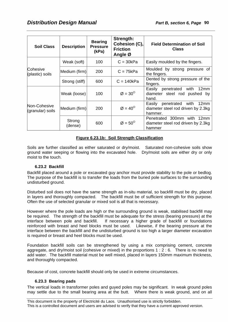
Distribution Design Manual Part B, section 6, Page
This document is the property of Electricité du Laos. Unauthorised use is strictly forbidden. This is a controlled document and users are advised to verify that they have a current approved version.
90
Soil Class Description Bearing
Pressure (kPa)
Strength: Cohesion (C), Friction Angle Ø
Field Determination of Soil Class
Weak (soft) 100 C = 30kPa Easily moulded by the fingers.
Medium (firm) 200 C = 75kPa Moulded by strong pressure of the fingers.
Cohesive (plastic) soils
Strong (stiff) 600 C = 140kPa Dented by strong pressure of the fingers.
Weak (loose) 100 Ø = 30O Easily penetrated with 12mm diameter steel rod pushed by hand.
Medium (firm) 200 Ø = 40O Easily penetrated with 12mm diameter steel rod driven by 2.3kg hammer.
Non-Cohesive (granular) soils
Strong (dense) 600 Ø = 50O
Penetrated 300mm with 12mm diameter steel rod driven by 2.3kg hammer
Figure 6.23.1b: Soil Strength Classification
Soils are further classified as either saturated or dry/moist. Saturated non-cohesive soils show ground water seeping or flowing into the excavated hole. Dry/moist soils are either dry or only moist to the touch.
6.23.2 Backfill Backfill placed around a pole or excavated guy anchor must provide stability to the pole or bedlog. The purpose of the backfill is to transfer the loads from the buried pole surfaces to the surrounding undisturbed ground. Disturbed soil does not have the same strength as in-situ material, so backfill must be dry, placed in layers and thoroughly compacted. The backfill must be of sufficient strength for this purpose. Often the use of selected granular or mixed soil is all that is necessary. However where the pole loads are high or the surrounding ground is weak, stabilised backfill may be required. The strength of the backfill must be adequate for the stress (bearing pressure) at the interface between pole and backfill. If necessary a higher grade of backfill or foundations reinforced with breast and heel blocks must be used. Likewise, if the bearing pressure at the interface between the backfill and the undisturbed ground is too high a larger diameter excavation is required or breast and heel blocks must be used. Foundation backfill soils can be strengthened by using a mix comprising cement, concrete aggregate, and dry/moist soil (cohesive or mixed) in the proportions 1 : 2 : 6. There is no need to add water. The backfill material must be well mixed, placed in layers 150mm maximum thickness, and thoroughly compacted.
Because of cost, concrete backfill should only be used in extreme circumstances.
6.23.3 Bearing pads The vertical loads in transformer poles and guyed poles may be significant. In weak ground poles may settle due to the small bearing area at the butt. Where there is weak ground, and on all

Distribution Design Manual Part B, section 6, Page
This document is the property of Electricité du Laos. Unauthorised use is strictly forbidden. This is a controlled document and users are advised to verify that they have a current approved version.
91
guyed poles, a bearing pad shall be installed at the base of the excavated hole to ensure vertical loads are transferred safely into the undisturbed ground. Usually a layer of strong granular material 150 to 300mm thick is all that is required.

Distribution Design Manual Part B, section 6, Page
This document is the property of Electricité du Laos. Unauthorised use is strictly forbidden. This is a controlled document and users are advised to verify that they have a current approved version.
92
6.24 Guying To provide additional horizontal strength to a pole at large angles or termination points, it is often necessary to fit a guy (also often called a stay) to an anchor buried in the ground. As an alternatives to the use of guys:
• A termination pole may be erected edge on to the conductor loads where the type of pole is stronger in the transverse direction than longitudinally.
• Two poles may be bolted together to approximately double the available strength rating. • Internal bracing may be fitted to a 2-pole structure.
In all cases particular attention must be given to the pole and stay foundations according to the applied conductor loads and the local soil conditions.
6.24.1 Guy design Guys are required to resist the horizontally applied conductor loads. In doing so the horizontal load is split into two components: a slope component in the staywire, and a vertical component in the pole. The optimum slope for a guy is 45o but this often occupies considerable ground space. Where the site is of limited size a steeper slope of approximately 30o to vertical (60o to the horizontal) may be used, but in doing so the increased load in the staywire must be allowed for.
It is usual to assume that the horizontal component of the conductor loads are supported by the stay, with the pole resisting the pole wind loads, pole and hardware mass (self-weight), and the vertical component of the conductor loads. Where a steep guy is installed or the conductor loads are large the buckling load in the pole should be checked.
6.24.2 Guying materials Guys usually comprise stranded staywire that is attached to the pole with special purpose hardware and made off just above ground level to an anchor bolt. The properties of standard staywires are shown in table 6.24.2a from data derived from AS 1222.1-199254. Stranding and wire diameter
(mm)
Overall diameter
(mm)
Cross-sectional
area (mm2) Mass per km (kg) Calculated breaking load (kN)
Standard grade High tensile grade 7/2.50 7.50 34.36 271 23.53 40.5 7/2.75 8.25 41.58 328 28.47 49.0 7/3.25 9.75 58.07 458 39.91 68.7 7/4.00 12.00 87.96 694 59.84 103
19/2.75 13.8 112.9 894 133
Table 6.24.2a: Standard staywires
The vertical component of the transferred conductor load that is in the pole may require a bearing pad at the base of the pole hole excavation to safely transfer the stress into the ground. The staywire is attached to the pole by an eyebolt fitted with a thimble. Alternative arrangements include a special purpose thimble eyebolt (of either straight or angle pattern), or angle thimble eye
54 AS 1222.1-1992. Steel conductors and stays – Bare overhead, Part 1: Galvanised (SC/GZ).

Distribution Design Manual Part B, section 6, Page
This document is the property of Electricité du Laos. Unauthorised use is strictly forbidden. This is a controlled document and users are advised to verify that they have a current approved version.
93
fitted to a standard bolt. In all cases the bolt strength rating must be adequate for the applied staywire load and a heavy-duty washer must be used under the nut on the bolt. At the ground end a stayrod (anchor rod) of sufficient length is used to develop the required holding strength in the local ground conditions. A range of strength/length combinations of stayrods is available as in table 6.24.2b.
Nominal length (mm)
Diameter (mm)
Minimum Failing Load (kN)
1800 16 62
2000 20 98
2500 24 141
Table 6.24.2b: Stayrods The staywire is made off to the eyes at the pole end and ground end on thimbles using a helically formed dead-end (guy grip, or preformed guy dead end). It is not necessary to provide any adjustment device in the guy assembly as the pole can usually be raked sufficiently before conductor loads are applied to allow for settlement of the stay assembly and the foundations. It is EdL practice to insert a guy insulator in every staywire. Guy insulators have traditionally been used so that in the event of an insulation breakdown on the pole the staywire does not become energised where persons can make contact55. The guy insulator must be located a minimum of 2.5m above the ground. The wet flashover voltage values are based 1.5 times the phase-earth voltage of the circuit. The guy insulator should be selected according to the voltage of the conductors adjacent to the attachment point on the pole. Two ratings of guy insulator are used as shown in table 6.24.2c.
50Hz Flashover Voltage (kV) Dry Wet
Minimum Failing Load
(kN)
LV (400/230v) 20 10 70
MV (22kV) 50 20 200
Table 6.24.2c: Guy strain insulators The buried deadman or anchor block may take different forms according to the ground conditions and the required holding strength. Whatever the form it is important that the anchor rod and staywire are correctly aligned so that there is no tendency for the anchor rod to deflect and thereby let the guy become slack. The holding strength of a stay foundation is a function of the soil characteristics and the foundation dimensions. For granular material:
55 The practice is hardly necessary with concrete poles, but is commonly retained.
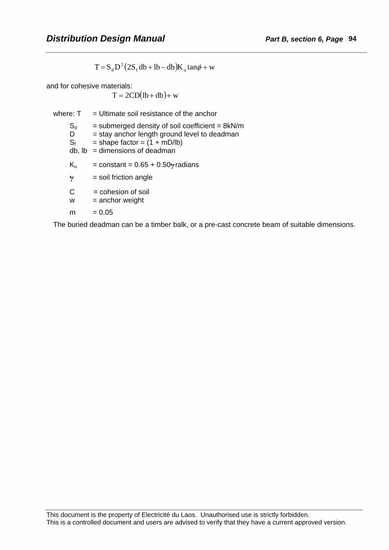
Distribution Design Manual Part B, section 6, Page
This document is the property of Electricité du Laos. Unauthorised use is strictly forbidden. This is a controlled document and users are advised to verify that they have a current approved version.
94
( ) wtanKdblbdb2SDS T uf2
d +−+= φ and for cohesive materials:
( ) wdblb2CDT ++=
where: T = Ultimate soil resistance of the anchor
Sd = submerged density of soil coefficient = 8kN/m D = stay anchor length ground level to deadman Sf = shape factor = (1 + mD/lb)
db, lb = dimensions of deadman
Ku = constant = 0.65 + 0.50¯radians
¯ = soil friction angle
C = cohesion of soil w = anchor weight
m = 0.05
The buried deadman can be a timber balk, or a pre-cast concrete beam of suitable dimensions.
Distribution Design Manual Part B, section 6, Page
This document is the property of Electricité du Laos. Unauthorised use is strictly forbidden. This is a controlled document and users are advised to verify that they have a current approved version.
95
6.25 LV Aerial Bundled Conductor
6.25.1 Characteristics Low voltage aerial bundled conductor (LVABC) is a fully insulated self-supporting overhead cable system that offers a number of technical and safety advantages. LVABC has come into widespread use in recent decades as the full technical advantages of the system have become recognised. These include:
• Enhanced safety because of the fully insulated construction. This is applicable to both authorised electrical workers and the general public.
• Reduced incidence of faults because of the fully insulated construction. • Superior performance when a fault or breakage occurs as the proximity of the LVABC
neutral ensures rapid evolution to a phase – neutral fault with fast clearance by the upstream fuses.
• Reduced volt drop because of the lower circuit impedance as a consequence of the close conductor spacing.
• Improved aesthetic appearance from the utilisation of one cable instead of four (up to about 4 x 70).
• Less visual impact by the elimination of crossarms, and insulators (not generally applicable to EdL).
• Reduced tree cutting both initially and for on-going maintenance. • Reduced illegal connections because of the difficulty of penetration of the insulation and the
need for special purpose connectors. • Lower lifetime costs from reduced maintenance and superior reliability. • Capability to attach the cable directly to buildings, which reduces the number of support
poles and simplifies the location of consumer connection points in locations where roadways are narrow and there are numerous consumer connections.
An extensive range of special purpose rationalised hardware is internationally available. The items simplify construction and achieve speedy erection, particularly the rebuilding of existing reticulation. Because the LVABC system is fully insulated there is a significantly reduced hazard to the public if supports or fittings should fail from external causes resulting in the cable falling to the ground or becoming accessible. To minimise consequential damage or cascade failures to the distribution network, deliberate “weak link” components can be provided to allow the cable to separate from the support in the event of abnormal mechanical loading such as a tree falling across a cable span. A suggested hierarchy of component strength features is:
• The first element to fail should be the suspension supports by release of the clamp or pole hardware.
• The second should be mains and service cable tee-off connections to minimise the number of live cables on or near the ground.
• The next elements to fail should be strain clamp pole hardware. • This should be followed by pole foundation failure, cable breaking, and lastly pole failure.
There are two types of LVABC in general international use. Both employ compacted all-aluminium conductors with crosslinked polyethylene (XLPE) insulation on all conductors including the neutral. The number of phase conductors may be two, three or four. Sometimes additional smaller aluminium conductor cores are included in the bundle for public lighting and similar purposes.
Distribution Design Manual Part B, section 6, Page
This document is the property of Electricité du Laos. Unauthorised use is strictly forbidden. This is a controlled document and users are advised to verify that they have a current approved version.
96
6.25.1.1 Mains cable Type A • The fully supported system (“German” system) that is commonly used in Norway, Sweden,
Austria, Germany, United Kingdom, New Zealand, Australia and many other countries. The phase and neutral conductors are all-aluminium and all are load bearing.
• The minimum breaking stress (all cores included) is approximately 140MPa that corresponds to a breaking load of 53.2kN for a 4 x 95mm2 cable.
• Phase and neutral conductors are of the same cross-section. Common sizes are 35mm2, 50mm2, 70mm2, 95mm2, 120mm2, and 150mm2, although usually only 50mm2, 95mm2, and 150mm2 are preferred.
• The phase cores are identified by continuous raised ribs approximately 0.5mm high with 1, 2 or 3 ribs on individual phases. The neutral core has between 14 and 24 evenly spaced ribs. In addition the phase cores are numbered at 100mm intervals.
• A typical national Standard is AS 3560-199156.
6.25.1.2 Mains cable Type B • The neutral supported system (or “French” system developed by Electricité de France) in
which the neutral conductor is a catenary messenger wire constructed from aluminium alloy and the phase conductors are all-aluminium. The mechanical load in the cable is carried by the neutral core alone.
• The minimum breaking stress (neutral only) is approximately 295MPa which corresponds to a breaking load of 20.7kN for the 70mm2 neutral core in a 3 x 95mm2 + 70mm2 cable.
• In France the neutral is insulated, but in Finland and some Middle Eastern counties a bare neutral is used. The neutral conductor is 54.6mm2, 70mm2 or 95mm2 and often of smaller cross-section than the phase conductors.
• Standard phase conductor sizes are 35mm2, 70mm2, 95mm2 and 150mm2. Cores are identified by a numbering system.
• Typical national Standards are NF C 33-209 and DIN VDE 0274.
6.25.1.3 Service cables Both systems use all-aluminium XLPE cables for service cables. Sizes are 16mm2 and 25mm2 in 2, 3 and 4 core construction. 1.5mm2 pilot cores are sometimes included. Core identification is by the method of the relevant national Standard. XLPE has been accepted as the best insulation for LVABC and in order to provide resistance to ultra-violet light degradation at least 2% carbon black pigment must be included. For enhanced performance at high temperatures (such as in forest fires), Australian research has shown the desirability of a high strength XLPE with 12% carbon black as this provides better adhesion to the conductor and greater strength at strain clamps.
6.25.2 LVABC hardware A feature of LVABC systems is the use of insulation piercing connectors (IPC’s) that are designed to be fully waterproof, completely insulated, and suitable for live installation. Correct installation is ensured by the use of shear head clamping bolts. IPC’s are used for service tee-offs and connecting jumpers and branch lines. Suspension clamps are used for cable support at tangent poles. The common form is a metal body with an attachment eye for fixing to a hook bolt. The clamp body encloses a resilient rubber (EPDM) insert to grip the cable without damage to the insulation. The standard clamp is suitable
56 AS3560-1991 “Electric cables - XLPE insulated - Aerial bundled - For working voltages up to and including 0.6/1kV”, Standards Australia.

Distribution Design Manual Part B, section 6, Page
This document is the property of Electricité du Laos. Unauthorised use is strictly forbidden. This is a controlled document and users are advised to verify that they have a current approved version.
97
for line deviations of up to approximately 30o. Larger angles 30o to 60o may use a double suspension clamp supported by a yoke bracket, or employ strain construction. Strain clamps are used for the termination of the LVABC cables. They are designed to hold the breaking load of the cable. According to the strength requirements there are a number of forms of construction. Most employ self-adjusting wedge shaped plastic inner sections to grip the cable cores with an external steel body clamped by bolts. Attachment to the pole is by steel straps, hooks, or bail loops. Full-tension and non-tension joints are made with insulated compression fittings that preserve the integrity of the insulation and remain waterproof. Pole fixing is commonly by hook-bolts or eyebolts. Where there are no suitable holes in the pole, support brackets are used which are secured in place by stainless steel banding. Mechanical weak link hooks can be used between the fittings and the pole mounted hook-bolts or eyebolts. The weak link hooks provide a controlled failure mechanism to drop the cable to the ground in the event of a tree falling on the line or other mechanical overload. Other components are usually specified to fail in a predetermined sequence to firstly minimise electrical safety, and secondly minimise damage.
6.25.3 Selection of cable system The fully supported Type A system is in more widespread international use than the neutral supported Type B system. The Type A system has the following advantages: Cable is cheaper to manufacture. Simpler to erect because all cores are supported at suspension and strain clamps. A full sized neutral is used. This is important where there is predominantly single-phase load with higher neutral currents. The mechanical load is shared by all cores not only the neutral. Higher tensions allow longer spans for the same sag limits. This may be important for reconstruction with existing pole spacing. There are some disadvantages however: The theoretical strength of type A cable usually cannot be fully utilised. The maximum tensile stress that can be transmitted through XLPE insulation at the strain clamps is usually limited to approximately 40MPa. To utilise the higher strength stronger poles or more guys are required. In the type B system, IPC’s are easier to install because there is no mechanical load on the phase cores allowing easier separation. Because of the practical difficulty of separating the cores to fit connectors the everyday tension of type A cable is usually limited to about 6kN. Table 6.24.3 compares the principal mechanical characteristics of the two systems for 95mm2 phase cores.

Distribution Design Manual Part B, section 6, Page
This document is the property of Electricité du Laos. Unauthorised use is strictly forbidden. This is a controlled document and users are advised to verify that they have a current approved version.
98
LVABC Type Neutral Supported (Type B)
Fully Supported (Type A)
Cable Description 3 x 95 + 70 mm2 4 x 95 mm2
Cross sectional area of stressed cores 70 mm2 4 x 95 = 380 mm2
Load bearing core conductor type AAAC AAC
Minimum breaking stress 295MPa 140MPa
Minimum Breaking Load (MBL) (70 x 295)/1000 = 20.7kN
(4 x 95 x 140)/1000 = 53.2kN
Max. Everyday Tension at 18% of MBL 20.7 x 0.18 = 3.7kN 53.2 x 0.18 = 9.6kN
Ultimate Limit State Max. Working Load 20.7 x 0.70 = 14.46kN 53.2 x 0.70 = 37.24kN
Serviceability Limit State Max. Working Load 20.7 x 0.50 = 10.35kN 53.2 x 0.50 = 26.6kN
Maximum Tension based on EDT 6.5kN Slack: 2.3kN Medium: 4.5kN Tight: 6.9kN
Maximum Tension based on XLPE stress (70 x 40)/1000 = 2.8kN (4 x 95 x 40)/1000 = 15.2kN
Practical Maximum Tension for core separation (approx.) n/a 6kN
Table 6.24.3: Comparison of Mechanical Properties of LVABC Systems
The hardware requirements for each system are similar although slightly different. There are few technical advantages in favour of either system in respect to hardware. As already noted both systems use similar cable and hardware for service lines. Type B cable has been installed under the Vientiane Rehabilitation project. Mains cable sizes used on the project are 4 x 70mm2 and 3 x 150 + 70mm2. EdL has installed small quantities of type A cable in some areas. On balance of technical characteristics the Type A system is superior and should be adopted for future work. However if funding sources prevent the adoption of Type A cable as standard, there are no major technical shortcomings with Type B. Regardless of which system is adopted, particular care must be taken in the specification and selection of hardware and accessories to ensure that the full technical and economic benefits of LVABC are realised.
6.25.4 Design Loadings For LVABC the same wind and temperature conditions should be as for single conductor construction. The overall diameter of the cable should be used when calculating the wind load. Maximum cable tensions need to be selected to limit the transverse load on angle poles and longitudinal load on termination poles. Large angles and all terminations will require appropriate guying where standard concrete poles are used. To reduce staying costs it is not economic to
Distribution Design Manual Part B, section 6, Page
This document is the property of Electricité du Laos. Unauthorised use is strictly forbidden. This is a controlled document and users are advised to verify that they have a current approved version.
99
utilise the full strength of the cable particularly where spans are short. With short span construction, reduced tensions can be adopted to simplify design and erection. Three tension conditions, slack, medium and tight are provided for in the sag/tension charts. These are based respectively on the maximum working load of a steep (30o) stay, a sag regime suitable for spans of up to about 70m, and full tension stringing for longer spans.

Distribution Design Manual Part B, section 6, Page
This document is the property of Electricité du Laos. Unauthorised use is strictly forbidden. This is a controlled document and users are advised to verify that they have a current approved version.
100
6.26 Electrical Protection
6.26.1 Purpose Switchgear and associated relays are required to provide rapid and predictable interruption of fault current in a reliable manner even if not called upon to operate for long periods of time. The devices must safely carry normal load current and respond only to specific abnormal conditions. Protection relays, fuses and other fault sensitive devices are installed to:
• Detect a fault condition, and • Initiate tripping.
The actual interruption of fault current is done with circuit breakers (and Reclosers) and fuses. This switchgear and other non-fault rated equipment also usually provide circuit isolation either automatically and/or manually. All switching devices must have adequate continuous rating for the maximum load current plus a margin for load growth. Load breaking devices have contacts and arc control systems designed to safely interrupt load current. This usually affords the capability to close on to a fault but not break the fault current. Switchgear rated to interrupt fault current can safely break the specified fault current a number of times and remain serviceable.
6.26.2 MV equipment Circuit breakers are used on feeders to control the feeder at source at the supply substation. A circuit breaker has the capability of safely interrupting fault current and load current. In the event of an overload or fault, protection relays detect the abnormal condition and initiate automatic tripping. Manual and electric trip and close facilities are usually provided. Reclosers are enclosed switches with fault and load current interrupting capability, fitted with fault detection coils or relays to initiate tripping, and arranged for automatic reclosing in a predetermined sequence. Manual trip and close facilities are usually provided. Reclosers are usually installed at strategic points along an MV feeder chosen so as restore supply to most consumers by the automatic isolation of a faulted section. Sectionalisers are enclosed type load break (but not fault interrupting) switches fitted with fault detection coils or relays to detect the passage of fault current and trip open during the dead time of an upstream Recloser or circuit breaker. Manual trip and close facilities are usually provided. Sectionalisers must be installed downstream from their co-ordinating Recloser. Enclosed switches (eg. SF6) and load breaking air break switches are rated to interrupt load current and close on to a fault, but not interrupt fault current. They have no protection relays to initiate operation and are usually manually operated. Dropout fuses have a fuse element rated to interrupt limited fault current which after melting releases a spring system to isolate the circuit. Dropout fuses are not rated to break load current unless the fuse link is ruptured. Apart from fault interruption, operation is manual.
Distribution Design Manual Part B, section 6, Page
This document is the property of Electricité du Laos. Unauthorised use is strictly forbidden. This is a controlled document and users are advised to verify that they have a current approved version.
101
Circuit breakers, Reclosers, Sectionalisers, and switches are usually three-phase gang operated even if a fault is detected on only one phase. Dropout fuses are single-phase devices. All of the above items are used for circuit isolation as well as fault clearance.
6.26.3 LV equipment At LV, transformer substations may be equipped with three-phase overcurrent circuit breakers. These operate automatically in the event of a fault or overload, but must be manually closed. Manual tripping facilities are always provided for circuit isolation. The most common type of protection at LV is with HRC fuses. At the transformer substation these may be gang operated, but on consumer supplies single-phase fuses are normal. Apart from fault interruption, operation is manual. Circuit isolation is usually by removal of the fuse carrier.
6.26.4 Discrimination All switchgear fitted with automatic tripping facilities should be arranged so that only the switchgear closest to the fault operates to permanently isolate the supply. Correct discrimination is achieved by selection of relay pickup and operating times according to the maximum and minimum fault levels at the point of installation and the ‘reach limit’ of the protection.
6.26.5 Protection relays The most common types of protection relays used at distribution voltages are overcurrent relays and earth fault relays each associated with various time delay devices. Overcurrent and earth fault relays have an operating time that is usually: • instantaneous with an operating time of a few tens of milliseconds, or • fixed time delay, or • of an inverse characteristic. The most time common time delay arrangement is the inverse curve that can be selected to be of similar response characteristic to standard fuses. Inverse characteristics may be standard, inverse, or extreme inverse all as defined in IEC and other standards. The response curves can usually be defined by an equation that simplifies the calculation of operating times. Most relays have a wide adjustment range for both pickup value and time setting.
6.26.6 MV Fuses “A fuse in an electric circuit stands guard at all times to protect the circuit, and the equipment connected to it, from overcurrent damage within the limits of its rating. How well this fuse will perform depends not only upon the accuracy with which it was manufactured, but also the correctness of the application and the attention it receives after it is installed. If not properly applied and maintained, considerable damage may occur to costly equipment. …Operational procedures that may lead to fault making or load switching shall be avoided …”57 For MV applications EdL uses NEMA class K fuse elements in dropout fuse carriers. Typical operating curves are included in Appendix B6.11. Type K fuse links according to NEMA specifications are required to carry rated current indefinitely, and to blow at approximately 220% of their rating in 300seconds. Other fuse types have different speed and characteristics and must not be interchanged on protection schemes where correct discrimination with other protective devices is based upon the use of type K fuses.
57 Extract from clause 11 of IEC60282-2 “High Voltage Expulsion Fuses”.

Distribution Design Manual Part B, section 6, Page
This document is the property of Electricité du Laos. Unauthorised use is strictly forbidden. This is a controlled document and users are advised to verify that they have a current approved version.
102
6.26.6.1 MV transformer fuses IEC60787 provides useful guidance on the selection of the rating of fuse links for the primary side of transformers. The main features may be summarised as:
• The pre-arcing time/current characteristic should be greater than the transformer inrush characteristic. This may be taken as 10 to 12 times full load current for duration of 0.1second.
• The current rating of the primary side fuse link should exceed the full load current of the transformer by an allowance for overloading of the transformer, and an amount for high ambient conditions.
• The pre-arcing current of the primary side fuse link should be as low as possible in the 10second region of the fuse-link time/current characteristic in order to ensure maximum protection for the transformer.
• For complete co-ordination of primary side and secondary side fuse-links the secondary side characteristic should intersect the primary side characteristic at a current greater than the maximum fault current at the load side of the secondary fuses.
These features are illustrated in Figure 1 of IEC60787 that is reproduced as Appendix B6.12. A table in section 8 shows the correct current rating for dropout fuse links for EdL standard size transformers. This table is based upon the likely transient currents in the fuse from transformer inrush, motor starting, etc and not the transformer full load rating. MV fuses are selected to provide fault protection not overload protection, and so have current rating considerably greater than the transformer full load.
6.26.6.2 MV spur line fuses Dropout fuses on MV spur lines should be rated 10amp maximum58. When selecting the ampere rating care must be taken to achieve discrimination with upstream protection devices, and wherever possible with the downstream transformer fuses. Where standard dropout fuses are installed on spur lines, they shall not be used for switching on load, as the contacts are not rated for switching load current. The fuses may be manually operated only for isolation purposes at no load. If this cannot be ensured suitable load break fuses should be installed.
6.26.7 LV fuses and circuit breakers Although the protective function of LV fuses and circuit breakers is similar to MV fuses the methods of application are different. Most LV fuses and circuit breakers used at the distribution level are not subject to inrush currents.59 The recommended basis for selection of LV fuses and circuit breakers is:
• Protection against the effects of indirect contact, and • Protection against short-circuit current that may damage upstream transformers and
downstream conductors and equipment, and • Protection against overloading that may result in excessive voltage drop, and • To ensure discrimination with fuses and other protective devices both upstream and
downstream. For safety of personnel in the event of an indirect contact LV fuses must be rated to clear within 5seconds60 a current defined by;
58 Refer section 6.5 for the maximum allowable connected transformer capacity. 59 Fuses used for motor circuit protection are required to withstand short-term high current loading at motor starting. Where large motors are connected it may be necessary to select distribution fuses accordingly. 60 The clearance time is 0.4 second for final sub-circuits on consumer premises.

Distribution Design Manual Part B, section 6, Page
This document is the property of Electricité du Laos. Unauthorised use is strictly forbidden. This is a controlled document and users are advised to verify that they have a current approved version.
103
IA ∗ UO / ZS where U0 is nominal phase voltage, and
Zs is the fault-loop impedance. As an overload device the LV fuse or circuit breaker must satisfy two conditions: IB ∗ IN ∗ IZ, and IA ∗ 1.45 x IZ for circuit breakers, or IA ∗ 1.60 x IZ for fuses.
where IB is the current for which the circuit is designed IN is the nominal current of the fuse or circuit breaker, IZ is the continuous current-carrying capacity of the cable, and IA is the operating current of the circuit breaker or the fusing current of the fuse.
The conventional tripping current If of fuses is 1.6 IN.61 This is the current that will cause operation within a stated time (1hour for fuses rated ∗ 63 amp, 2hour for fuses rated over 63 amp but ∗ 160 amp, 3hour for fuses rated over 160 amp but ∗ 400 amp, and 4 hour for fuses rated over 400 amp). For co-ordination with circuit breakers fuses are derated to 0.9 IN. (The factor 0.9 is derived from 1.45/1.60).
The overcurrent performance of the fuse or circuit breaker must be chosen with a time-current characteristic that will co-ordinate with upstream and downstream protective devices. This is generally assured if the total I2t of the downstream fuses does not exceed the pre-arcing I2t of the upstream fuse62. The correct operation of fuses and circuit breakers are an important consideration in the design of LV distributors. The characteristics of LV fuses are defined in IEC60269 and are often described as BS88 type. These are enclosed current limiting fuses sometimes described as HRC type. There are numerous types of fuse characteristics63 for low voltage service but for transformer and overhead line protection general-purpose fuse-links (type ‘g’ of IEC60269-1) are appropriate. The particular tag or end fitting on the fuse link must be specified to suit the apparatus in which the fuse is mounted. DIN pattern fuses are recommended for distribution applications as the contact arrangements are:
• Simple to operate requiring only low forces. • Require no clamping or screwing once inserted. • Have a high contact pressure with a self-wiping action. • Suitable for on load insertion or removal without damage to the contact surfaces.
6.26.7.1 Protection against indirect contact To minimise hazard from indirect contact, fuses and circuit breakers on the LV distribution network must operate within 5 seconds. To ensure this, the fault loop impedance ZS must be sufficiently low.
61 See Table II of IEC60269-1. 62 I2t , the ampere2 seconds, is the let through energy under short-circuit conditions. 63 Eg. Motor start, semiconductor, etc
Distribution Design Manual Part B, section 6, Page
This document is the property of Electricité du Laos. Unauthorised use is strictly forbidden. This is a controlled document and users are advised to verify that they have a current approved version.
104
The corollary is that for a given fuse rating and circuit conductor cross-section, there is a maximum allowable circuit length. The fault loop path for a single-phase to earth or a phase to neutral fault will comprise the affected length of the phase conductor plus the corresponding length of neutral conductor. Where the neutral is regularly earthed the contribution of the earth path to the reduction in the impedance of the fault loop path is usually ignored as it is of much higher impedance than the neutral conductor. The relevant voltage for the loop impedance is based upon the standard phase-neutral voltage even for poly-phase circuits.
IEC60269-1 defines the maximum permissible fuse operating current at 5second for each nominal fuse rating. The fault loop impedance is given by:
ZS ∗ UO / IA where U0 = phase-neutral voltage
It is conventionally assumed that there will always be at least 80% of the nominal phase-neutral voltage at the location of the protective device. Hence:
Zmax ∗ 0.8 UO / IA
This expression can be expressed in terms of the circuit length of the respective phase and neutral conductors:
( )npha
nph0max SSI
SSU8.0L
+ρ=
where: Lmax = maximum length in metre
U0 = nominal phase-neutral voltage ρ = resistivity of conductor material at normal working temperature Ia = instantaneous trip current setting of the circuit breaker,or operating current of the fuse in the specified time Sph = cross-sectional area of the phase conductor in mm2 Sn = cross-ectional area of the neutral conductor in mm2
This expression is reliable only where the conductors comprising the fault loop are in close proximity to each other and for sizes up to 120mm2. The worst case fault may be considered as at the consumer installation end of a service line/main at the extremity of the LV distributor. The consumer fuse or circuit breaker would usually be provided at this location. A spreadsheet of the calculations is shown in Appendix B6.13. Maximum lengths for standard fuse ratings and EdL standard conductors with 20m of 10mm2 aluminium service line/main are shown in table 6.26.7.1.
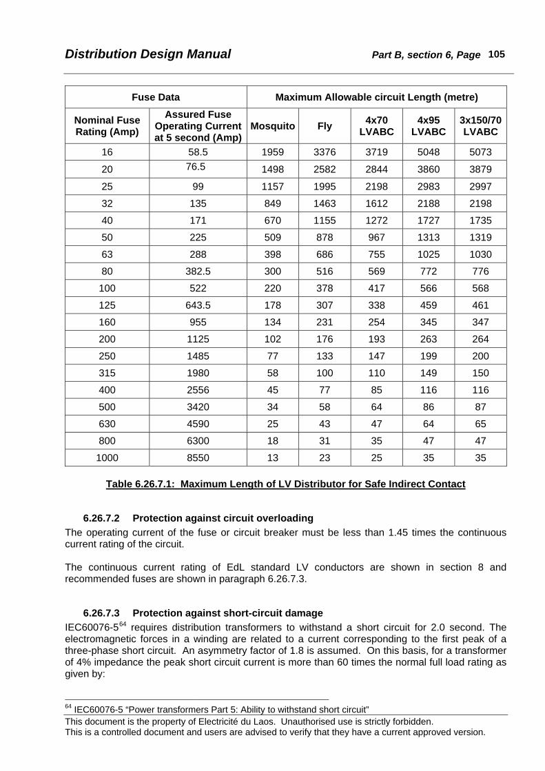
Distribution Design Manual Part B, section 6, Page
This document is the property of Electricité du Laos. Unauthorised use is strictly forbidden. This is a controlled document and users are advised to verify that they have a current approved version.
105
Fuse Data Maximum Allowable circuit Length (metre)
Nominal Fuse Rating (Amp)
Assured Fuse Operating Current at 5 second (Amp)
Mosquito Fly 4x70 LVABC
4x95 LVABC
3x150/70LVABC
16 58.5 1959 3376 3719 5048 5073
20 76.5 1498 2582 2844 3860 3879
25 99 1157 1995 2198 2983 2997
32 135 849 1463 1612 2188 2198
40 171 670 1155 1272 1727 1735
50 225 509 878 967 1313 1319
63 288 398 686 755 1025 1030
80 382.5 300 516 569 772 776
100 522 220 378 417 566 568
125 643.5 178 307 338 459 461
160 955 134 231 254 345 347
200 1125 102 176 193 263 264
250 1485 77 133 147 199 200
315 1980 58 100 110 149 150
400 2556 45 77 85 116 116
500 3420 34 58 64 86 87
630 4590 25 43 47 64 65
800 6300 18 31 35 47 47
1000 8550 13 23 25 35 35
Table 6.26.7.1: Maximum Length of LV Distributor for Safe Indirect Contact
6.26.7.2 Protection against circuit overloading The operating current of the fuse or circuit breaker must be less than 1.45 times the continuous current rating of the circuit. The continuous current rating of EdL standard LV conductors are shown in section 8 and recommended fuses are shown in paragraph 6.26.7.3.
6.26.7.3 Protection against short-circuit damage IEC60076-564 requires distribution transformers to withstand a short circuit for 2.0 second. The electromagnetic forces in a winding are related to a current corresponding to the first peak of a three-phase short circuit. An asymmetry factor of 1.8 is assumed. On this basis, for a transformer of 4% impedance the peak short circuit current is more than 60 times the normal full load rating as given by:
64 IEC60076-5 “Power transformers Part 5: Ability to withstand short circuit”

Distribution Design Manual Part B, section 6, Page
This document is the property of Electricité du Laos. Unauthorised use is strictly forbidden. This is a controlled document and users are advised to verify that they have a current approved version.
106
ampereVz
10028.1II FLsc =
Standard general purpose fuses of nominal rating similar to the full-load rating of a transformer have an operating I2t clearance time of the order of one cycle (0.02 second) or less at short-circuit currents and so will adequately protect a transformer. The 1.0 second fault rating of EdL standard overhead conductors are shown in section 8, and generally lie in the range 2kA to 4kA. At 2kA general purpose fuses of up to 250amp will clear within 1.0 second, and at 4kA fuses of up to 400amp will clear within 1.0 second. Standard fuses will afford adequate protection against conductor damage from excessive heating, refer table 6.26.7.3.
Standard Conductor
Continuous Current Rating (Amp)
1.0 second Fault Rating (Amp)
Maximum Nominal Fuse Rating
Mosquito 140 2130 100
Fly 192 3670 125
4x70LVABC 180 4090 125
4x95LVABC 220 5550 160
3x150/70LVABC 290 8770 200
Table 6.26.7.3: Maximum Fuse Rating for Standard Conductors
6.26.7.4 LV fuse discrimination The rating of a fuse must be chosen so as to discriminate correctly with the upstream and downstream protection devices and the thermal or mechanical rating of the circuit or equipment it is designed to protect. A typical relationship with a cable is shown in Figure 6.26.7.4.
Figure 6.26.7.4: Typical Overcurrent Protection of Conductors
Time
Time/Current Characteristic
Time/Current Characteristic
I2tTime/Cable Characteristic
Current

Distribution Design Manual Part B, section 6, Page
This document is the property of Electricité du Laos. Unauthorised use is strictly forbidden. This is a controlled document and users are advised to verify that they have a current approved version.
107
Discrimination of fuses in series is assured if the total I2t of the downstream fuses does not exceed the pre-arcing I2t of the upstream fuse. The I2t characteristics of IEC60269-1 fuses are illustrated in Appendix B6.14. It is apparent that some adjacent standard nominal ratings will not discriminate correctly.
In List A or List B below, fuses of the nominal current ratings shown will discriminate (grade) satisfactorily with the next higher or lower rating in that list.
List A 20 - 32 - 50 - 80 - 125 - 200 - 355 - 450 - 630 - 800amp. List B 25 - 40 - 63 - 100 - 160 - 250 - 315 - 400 - 500 amp.
eg. An 80amp fuse will discriminate satisfactorily with a 125amp fuse upstream and a 50amp fuse downstream. Similarly, a 160amp fuse will be satisfactory with 250amp and 100amp fuses.

Distribution Design Manual Part B, section 6, Page
This document is the property of Electricité du Laos. Unauthorised use is strictly forbidden. This is a controlled document and users are advised to verify that they have a current approved version.
108
6.27 Metering
6.27.1 Installation All supplies to consumers shall be metered to ensure there is a correct record of electricity use and for charging at the appropriate tariff. This should include EdL owned premises even if there is no charge for the energy used. Supplies that are not metered represent a loss of revenue to EdL and make difficult the correct allocation of energy flows and losses. Meters must be installed according to relevant Standards and in accordance with manufacturer’s instructions. Particular care shall be taken that Ferraris65 meters are erected within 3 degrees of true vertical. All meters shall be securely fixed in position and accessible terminals sealed following the connection of incoming and outgoing circuits. Unless the meters are designed and marked for outdoor use meters must be installed indoors or in a weatherproof enclosure. Meters shall be accessible at all times for regular consumption readings, inspection and servicing. Standard meter connection diagrams are shown in Appendix B6.15. Care must be taken when installing polyphase meters that:
• phase rotation is the same as that used when the meter was calibrated, • currents are associated with the correct voltage according to the meter type. This can be
facilitated by the use of standard wiring diagrams and standardised colour coded wiring, Additional checks are required when installing CT-operated meters that:
• the polarity of CT’s is correct. This is often done by marking the CT body with a “dot” or other coding to show the polarity as proven after testing in the laboratory. Refer Figure 6.26.1,
• correct multipliers are recorded. The adoption of the CT metering practices described later in this section should alert an observant person to mistakes in multipliers.
Errors in the secondary wiring, phasing and polarity of CT’s and corresponding VT’s are a common cause of metering errors. Of similar importance is the correct calculation and recording of multipliers. To minimise these errors it is good practice to use a different person from the installer to independently check/inspect all CT metered installations before or during commissioning.
The CT body or primary terminals should be marked “P1” and “P2” with an arrow in the direction P1 to P2, and the corresponding secondary terminals identified as in the diagram. Alternatively, the CT body or primary terminal P1 may be marked with a “dot” or colour code, and the corresponding secondary terminal S1 similarly marked.
Figure 6.27: Polarity Coding of Metering Current Transformers
65 Ferraris meters are conventional rotating disc type.
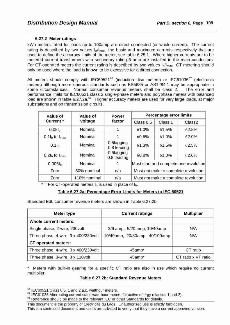
Distribution Design Manual Part B, section 6, Page
This document is the property of Electricité du Laos. Unauthorised use is strictly forbidden. This is a controlled document and users are advised to verify that they have a current approved version.
109
6.27.2 Meter ratings kWh meters rated for loads up to 100amp are direct connected (or whole current). The current rating is described by two values Ib/Imax, the basic and maximum currents respectively that are used to define the accuracy limits of the meter, see table 6.25.1. Where higher currents are to be metered current transformers with secondary rating 5 amp are installed in the main conductors. For CT-operated meters the current rating is described by two values In/Imax. CT metering should only be used where the load is known to be excessive for a direct connection. All meters should comply with IEC6052166 (induction disc meters) or IEC6103667 (electronic meters) although more onerous standards such as BS5685 or AS1284.1 may be appropriate in some circumstances. Normal consumer revenue meters shall be class 2. The error and performance limits for IEC60521 class 2 single-phase meters and polyphase meters with balanced load are shown in table 6.27.2a.68 Higher accuracy meters are used for very large loads, at major substations and on transmission circuits.
Percentage error limits Value of Current *
Value of voltage
Power factor Class 0.5 Class 1 Class2
0.05Ib Nominal 1 61.0% 61.5% 62.5%
0.1Ib to Imax Nominal 1 60.5% 61.0% 62.0%
0.1Ib Nominal 0.5lagging 0.8 leading 61.3% 61.5% 62.5%
0.2Ib to Imax Nominal 0.5lagging 0.8 leading 60.8% 61.0% 62.0%
0.005Ib Nominal 1 Must start and complete one revolution
Zero 80% nominal n/a Must not make a complete revolution
Zero 110% nominal n/a Must not make a complete revolution* = For CT-operated meters In is used in place of Ib.
Table 6.27.2a: Percentage Error Limits for Meters to IEC 60521 Standard EdL consumer revenue meters are shown in Table 6.27.2b:
Meter type Current ratings Multiplier
Whole current meters:
Single phase, 2-wire, 230volt 3/9 amp, 5/20 amp, 10/40amp N/A
Three phase, 4-wire, 3 x 400/230volt 10/40amp, 20/80amp, 40/100amp N/A
CT operated meters:
Three phase, 4-wire, 3 x 400/230volt -/5amp* CT ratio
Three phase, 3-wire, 3 x 110volt -/5amp* CT ratio x VT ratio * Meters with built-in gearing for a specific CT ratio are also in use which require no current multiplier.
Table 6.27.2b: Standard Revenue Meters
66 IEC60521 Class 0.5, 1 and 2 a.c. watthour meters. 67 IEC61036 Alternating current static watt-hour meters for active energy (classes 1 and 2). 68 Reference should be made to the relevant IEC or other Standards for details.
Distribution Design Manual Part B, section 6, Page
This document is the property of Electricité du Laos. Unauthorised use is strictly forbidden. This is a controlled document and users are advised to verify that they have a current approved version.
110
Single-phase supplies should be metered with single phase 220volt meters. Three-phase LV supplies should use 3-phase 4-wire (3 element) 400/230volt meters. The use of single-phase meters on two-phase and three-phase supplies should be avoided as they may run in reverse if the load power factor is less than 0.5 (eg. some electric arc welding plant). Three phase 3-wire meters are used for HV and MV metering where the load is balanced or nearly balanced. 3-wire meters (2 element) are used to economise on the number of high voltage CT’s and VT’s required. Voltage transformers and current transformers are required for isolation from the HV or MV supply. The secondary voltage is usually 110volt, and the secondary current is 5 amp. These meters often have large multipliers unless the constant is built in to the meter gearing. Accuracy limits are the same as for 400volt and 230volt meters. It should be noted that three-phase three-wire meters and three-phase four-wire meters both accurately record energy for all power factors and unbalance. Refer to Appendix B6.16 for an explanation. A more detailed proof can be found in most standard textbooks. The choice of which to use is related to the costs of CT’s and VT’s and the ease of installation as discussed above.
6.27.3 Meter Multipliers All CT meters should be purchased as -/5amp and NOT with built-in multiplier for a particular CT ratio. This considerably simplifies meter installation, as a meter need not be matched to a particular CT ratio. A smaller range of meters can be stocked (only one LV CT meter stock item is needed in place of one for each CT ratio). There is less confusion in applying multiplier constants, as the current multiplier is simply the CT ratio. The ratios will be reasonably large (40, 80, etc) so an error in application will be more obvious than with built-in multipliers. The EdL billing system can readily accommodate meter multipliers and procedures for checking input data already exist. Meters used for MV or HV metering also require a multiplier to correspond to the voltage transformer ratio eg. 22,000/110volt that gives a voltage multiplier of 200. These meters will have an overall multiplier comprising the product of the current and voltage multipliers. It should be noted that meters to IEC60521 are required to be accurate within 610% of the nameplate voltage rating. Therefore a voltage multiplier is only required when a voltage transformer is used. Meter registers should be of the drum type. All registers should be six-drum and record directly in kWh69. Direct connected meters should not have a decimal drum. CT operated meters should have the decimal point marked and have two decimal drums – these are required by IEC60521 to be coloured (and are usually red). The lowest recording drum is graduated into 100 divisions.
6.27.4 Guidelines as to Selection of 3-phase Metering Arrangements The following information relates to the selection of appropriate metering arrangements for individual consumers taking three-phase supply. All meters for three-phase LV supplies should be of the 4-wire (3-element) type because the loads may be single phase or significantly unbalanced. At LV the neutral is always available for the voltage supply. 4-wire meters that utilise phase-neutral voltages are also simpler to connect in the field with less risk of wiring errors that can result in phase transpositions. 69 Other multiples must be avoided. Care should be taken with older meters that may have other units eg.100kWh.

Distribution Design Manual Part B, section 6, Page
This document is the property of Electricité du Laos. Unauthorised use is strictly forbidden. This is a controlled document and users are advised to verify that they have a current approved version.
111
Class 2 meters to IEC60521 are suitable for consumer MV and LV metering up to 2000kVA. These are required to have errors less than ±2% over the range 0.1Ib to Imax (typically 2.5% to 100% maximum current) at unity power factor. There is no loss of meter accuracy provided the load is within these limits. Higher accuracy meters are usually chosen for major substations and consumer loads in excess of about 2000kVA. These may be of accuracy class 1, class 0.5 or class 0.2. Where higher accuracy meters are used corresponding higher accuracy grade CT’s and VT’s should be installed.
6.27.5 LV meter selection All LV meters should be single phase 220volt, or 3-phase 4-wire 380/220volt.
6.27.5.1 Direct connected (whole current) Direct connected 400/230volt meters should be used for all supplies up to 100amp (70kVA). The maximum current rating of the meter (Imax) should approximately match the expected maximum demand of the installation. Regard should also be given to the minimum installation load to ensure that the selected meter has a suitable Ib. Single-phase and three-phase meters are readily available up to 100amp. The rating of whole current meters in common use by EdL are listed in Table 6.27.2b. Short-term overloads in excess of the Imax rating will in general not damage a meter although accuracy may be lost. At LV, 4-wire meters are used for 3-phase systems because the neutral is available.
6.27.5.2 Current transformer metered Where the maximum current is expected to exceed 100amp and up to 750amp (nominal 70kVA to 500kVA) metering should be at 400/230volt utilising 3-element 4-wire meters with -/5amp current rating, and be used with 200/5, 400/5, or 800/5 current transformers. In particular cases, this metering arrangement may be utilised for supplies of up to 1000kVA utilising 1200/5, or 1500/5 current transformers. The range of standard LV current transformers can be rationalised as in table 6.26.5.2 to only three standard ratios; 200/5, 400/5 and 800/5. Higher ratios should only be used with specific approval because MV metering is normally more appropriate. Measurement grade CT’s should be 10VA Class 3 in accordance with IEC60044-1. These have a maximum error of ±3% from 50% to 120% of rated current and are suitable for installations up to 2000kVA capacity. If there is a known additional burden from extra meters, recording instruments or ammeters, CT’s of higher rated burden up to 30VA should be specified. For LV 3-phase 4-wire CT metering three CT’s are required, one in each phase conductor. To provide more flexibility and to avoid the disruption caused by CT replacement when the consumer load changes, some organisations use multiple ratio CT’s. Suitable for EdL would be: 200/100/5, 400/200/5, 800/400/5, etc

Distribution Design Manual Part B, section 6, Page
This document is the property of Electricité du Laos. Unauthorised use is strictly forbidden. This is a controlled document and users are advised to verify that they have a current approved version.
112
Installation Maximum Demand
Standard Transformer
Rating CT Ratio
(Amp) (kVA) (kVA) Minimum Recommended
Multiplier
100 69 100 (use whole current meter) N/A 200 139 160 200/5 200/5 40 300 208 250 300/5 400/5 80 400 277 315 400/5 400/5 80 500 346 400 500/5 800/5 160 700 485 500 700/5 800/5 160 800 554 630 800/5 800/5 160
1000 693 800 1000/5 1200/5 240 1250 866 1000 1250/5 1200/5 240 1500 1039 1000 1500/5 1500/5 300
Table 6.27.5.2: CT’s for LV Metering
6.27.6 MV meter selection MV metering shall be used where:
• The LV current is expected to exceed 750amp (500kVA). This implies a sole use transformer.
• Supply is given to privately owned lines at MV. • Supply is given to privately owned transformers.
For MV metering the CT’s and PT’s are necessary to provide safety isolation from the 22kV circuit. The CT’s should be 20VA Class 3 in accordance with IEC60044-1. Higher grade CT’s (eg. Class 1.0 or 0.5) can be specified for special applications such as bulk metering at a major substation. Only meters with -/5 amp current rating should be purchased. The standard voltage transformer secondary is 110volt, and 3-phase 3-wire meters must be used, so meters different from LV metering are required. The overall multiplier is the product of the CT and PT ratios. If meters with a built-in constant for the PT ratio are used then the multiplier is simply the CT ratio. See Table 6.27.6.
Installation Maximum Demand
Standard Transformer CT Ratio
(Amp) (kVA) Rating (kVA)
Full Load (Amp @
22kV) Minimum Standard
Multiplier for
Standard Ratio
PT Ratio for
22kV/110v
Overall Multiplier
with Standard
CT
200 139 160 4.20 5/5 10/5 2 200 400 400 277 315 8.27 10/5 10/5 2 200 400 600 416 500 13.12 20/5 20/5 4 200 800 800 554 630 16.53 20/5 20/5 4 200 800 1000 693 800 20.99 30/5 20/5 4 200 800 1250 866 1000 26.24 30/5 30/5 6 200 1200 1500 1039 1000 26.24 30/5 30/5 6 200 1200 2000 1386 1500 39.36 40/5 40/5 8 200 1600 3000 2078 2000 52.49 60/5 50/5 10 200 2000
Table 6.27.6: CT’s for MV Metering

Distribution Design Manual Part B, section 6, Page
This document is the property of Electricité du Laos. Unauthorised use is strictly forbidden. This is a controlled document and users are advised to verify that they have a current approved version.
113
For MV 3-phase 3-wire metering two single-phase voltage transformers and two single-phase CT’s are required.
6.27.6.1 Ownership of Metering Equipment Where EdL meters the supply at LV: 1. Whole current meters and accessories will be supplied, installed, tested and inspected by EdL 2. CT meters, LV CT’s, test block and accessories will be supplied, installed, tested and
inspected by EdL. Space for the CT’s, test block and accessories shall be provided by the consumer.
Where MV metering is used: 1. MV metering equipment (2 x 22kV/110v PT, 2 x -/5amp CT, 3-phase 3-wire kWh meter, and
accessories) must always be installed, tested and inspected by EdL. 2. Where the transformer is greater than 250kVA, and is owned by EdL, there will be no charge to
the consumer for the MV metering installation. 3. Where the transformer is up to and including 500kVA, is owned by EdL, and EdL chooses to
meter at MV, there will be no charge to the consumer for the metering installation. (Normally supplies up to 500kVA will be metered at LV)
6.27.7 Meter test blocks It is good metering practice to routinely test CT operated three-phase meters to ensure that calibration remains within tolerance. This is often done on-site with the meters in their service position by injecting test currents from portable meter testing equipment. To facilitate this testing a meter test block should be wired into the CT and PT circuits as this enables the ready connection of temporary leads without disturbing permanent wiring. A meter test block comprises on the CT (input) side of the block:
• three current connections with short circuiting facilities, and • four voltage connections with isolation facilities.
On the meter side the test block has isolating links for the current circuits, and terminals for external leads are provided for current injection and an external voltage supply. Wiring arrangements incorporating a test block are shown in Appendix B6.15.
The test block must have a secure cover with sealing facilities.
If a meter test block is not installed, there should be a secure arrangement to short circuit the CT’s to permit meter replacement or testing.
6.27.8 Voltage supply fuses To protect transformer operated (CT and PT) metering equipment from damage from external surges, low voltage fuses should be provided in the voltage supply circuit as close to the busbars as practical70. To minimise extraneous operation these fuses should be generously rated and of robust construction (say 10amp HRC) with facilities for sealing.
70 Whole current meters do not have separate voltage supplies.

Distribution Design Manual Part B, section 6, Page
This document is the property of Electricité du Laos. Unauthorised use is strictly forbidden. This is a controlled document and users are advised to verify that they have a current approved version.
114
6.27.9 Standard metering wiring connections Appendix B6.15 illustrates a number of standard arrangements for the external wiring connections to metering equipment.
6.27.10 Tariff Meters Conventional meters record kWh and are used where the charge to the consumer is based on the energy (kWh) used. Multi-rate meters have several registers which are switched to record energy use at different times (of the day or week) so that alternative rates per kWh can be charged for consumption at those times. Switching between registers can be done locally by timeswitch, or remotely by pilot wires or mains borne signals. The sum of the register readings is the total energy passed through the meter. For the determination of power factor, energy meters can be purchased that measure kVArh directly. These are in effect kWh meters with the voltages shifted 90o and adjusted in value to compensate for the actual applied voltage rather than the line voltage or phase-neutral voltage. This can also be achieved by connecting a kWh meter with voltages shifted 90o, and modifying the gearing or utilising a multiplier to compensate for the different voltage. Other connection arrangements are described in standard metering texts. When a kVArh meter is used in conjunction with a kWh meter the average power factor over the period between meter readings can be readily determined. Since:
22 )kVArh()kWh(kVAh +=
the average power factor is:
kVAhkWhcos =φ
This can be the basis of an additional penalty charge or rebate if the installation has an average power factor different from the required minimum.71 Modern solid state meters commonly provide for the measurement and recording of both active and reactive energy, power factor, and maximum demand within the same unit.
71 One method is to express the tariff in two parts, the first for energy (kWh) and the other a penalty or bonus based on kWh x P/cosφ where P is the lowest permissible power factor. For example if the required power factor is 0.95 but the installation has an average power factor of 0.89 there would a penalty energy charge based on 0.95/0.89 = 1.0674 x actual kWh.
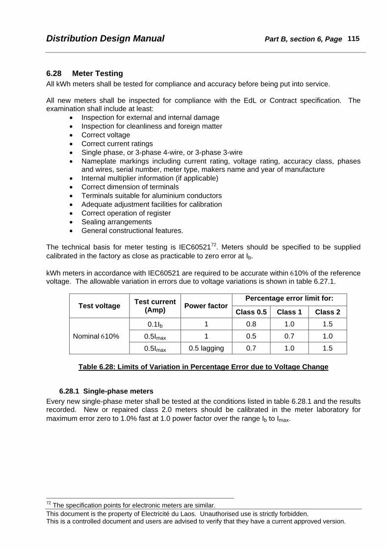
Distribution Design Manual Part B, section 6, Page
This document is the property of Electricité du Laos. Unauthorised use is strictly forbidden. This is a controlled document and users are advised to verify that they have a current approved version.
115
6.28 Meter Testing All kWh meters shall be tested for compliance and accuracy before being put into service. All new meters shall be inspected for compliance with the EdL or Contract specification. The examination shall include at least:
• Inspection for external and internal damage • Inspection for cleanliness and foreign matter • Correct voltage • Correct current ratings • Single phase, or 3-phase 4-wire, or 3-phase 3-wire • Nameplate markings including current rating, voltage rating, accuracy class, phases
and wires, serial number, meter type, makers name and year of manufacture • Internal multiplier information (if applicable) • Correct dimension of terminals • Terminals suitable for aluminium conductors • Adequate adjustment facilities for calibration • Correct operation of register • Sealing arrangements • General constructional features.
The technical basis for meter testing is IEC6052172. Meters should be specified to be supplied calibrated in the factory as close as practicable to zero error at Ib. kWh meters in accordance with IEC60521 are required to be accurate within 610% of the reference voltage. The allowable variation in errors due to voltage variations is shown in table 6.27.1.
Percentage error limit for: Test voltage Test current
(Amp) Power factor Class 0.5 Class 1 Class 2
0.1Ib 1 0.8 1.0 1.5
0.5Imax 1 0.5 0.7 1.0 Nominal 610%
0.5Imax 0.5 lagging 0.7 1.0 1.5
Table 6.28: Limits of Variation in Percentage Error due to Voltage Change
6.28.1 Single-phase meters Every new single-phase meter shall be tested at the conditions listed in table 6.28.1 and the results recorded. New or repaired class 2.0 meters should be calibrated in the meter laboratory for maximum error zero to 1.0% fast at 1.0 power factor over the range Ib to Imax.
72 The specification points for electronic meters are similar.

Distribution Design Manual Part B, section 6, Page
This document is the property of Electricité du Laos. Unauthorised use is strictly forbidden. This is a controlled document and users are advised to verify that they have a current approved version.
116
Test current (Amp) Test voltage Power factor Percentage error limit for Class 2
0.05Ib Nominal 1.0 62.5
Ib Nominal 1.0 62.0
Imax Nominal 1.0 62.0
0.1Ib Nominal 0.5 lagging 62.5
Ib Nominal 0.5 lagging 62.0
Imax Nominal 0.5 lagging 62.0
0.005Ib Nominal 1.0 Must start and complete one revolution
Zero 80% nominal n/a Must not make a complete revolution
Zero 110% nominal n/a Must not make a complete revolution
The “nominal” voltage is 220volt or as marked on the nameplate.
Table 6.28.1: Acceptance Tests for Single-Phase kWh Meters
6.28.2 Three-phase whole current meters Every new three-phase meter shall be tested at the conditions listed in table 6.28.2 and the results recorded. The first section of table 6.28.2 shows the requirements when balanced three-phase currents are used. In addition three-phase meters shall be tested with a single-phase current applied to each phase in turn as shown in the second part of table 6.28.2. New or repaired class 2.0 meters should be calibrated in the meter laboratory for maximum error zero to 1.0% fast at 1.0 power factor over the range Ib to Imax. Class 1.0 and class 0.5 meters should be adjusted for maximum error zero to 0.5% fast and zero to 0.2% fast respectively.
Percentage error limit for: Test current (Amp) Balanced three-phase Voltage Power
factor Class 0.5 Class 1 Class 2 0.05Ib Nominal 1.0 61.0 61.5 62.5
Ib Nominal 1.0 60.5 61.0 62.0
Imax Nominal 1.0 60.5 61.0 62.0
0.1Ib Nominal 0.5 lagging 61.3 61.5 62.5
Ib Nominal 0.5 lagging 60.8 61.0 62.0
Imax Nominal 0.5 lagging 60.8 61.0 62.0 0.005 Ib Nominal 1.0 Must start and complete one revolution
Zero 80% nominal n/a Must not make a complete revolution
Zero 110% nominal n/a Must not make a complete revolution
(continued on next page)

Distribution Design Manual Part B, section 6, Page
This document is the property of Electricité du Laos. Unauthorised use is strictly forbidden. This is a controlled document and users are advised to verify that they have a current approved version.
117
Percentage error limit for: Test current (Amp) Single-phase Voltage Power
factor Class 0.5 Class 1 Class 2 0.2Ib Nominal 1.0 61.5 62.0 63.0
Ib Nominal 1.0 61.5 62.0 63.0
Imax Nominal 1.0 - - 64.0
0.5Ib Nominal 0.5 lagging 61.5 62.0 -
Ib Nominal 0.5 lagging 61.5 62.0 63.0
0.015Ib Nominal 1.0 Must start and complete one revolution
Zero 80% nominal n/a Must not make a complete revolution
Zero 110% nominal n/a Must not make a complete revolution The “nominal” voltage is 380/220volt or as marked on the nameplate.
Table 6.28.2: Acceptance Tests for Three-Phase Whole Current kWh Meters
6.28.3 Three-phase 4-wire CT operated meters Every new three-phase 4-wire LV CT operated meter shall be tested at the following conditions and the results recorded.
• Where In and Imax are stated three-phase 4-wire current transformer operated LV meters shall be tested at the same test points as for whole current meters. See Table 6.28.3.
• Where only a single rating is stated, three-phase 4-wire current transformer operated LV meters shall be tested at the rated CT current (eg. 5amp). See Table 6.27.3.
New or repaired class 2.0 meters should be calibrated in the meter laboratory for maximum error zero to 1.0% fast at 1.0 power factor at In or over the range In to Imax. Class 1.0 and class 0.5 meters should be adjusted for maximum error zero to 0.2% fast and zero to 0.2% fast respectively.
Percentage error limit for: Test current (Amp) Balanced three-phase Voltage Power
factor Class 0.5 Class 1 Class 2 0.05In * Nominal 1.0 61.0 61.5 62.5
0.5In * Nominal 1.0 60.5 61.0 62.0
In * Nominal 1.0 60.5 61.0 62.0
0.1In * Nominal 0.5 lagging 61.3 61.5 62.5
0.5In * Nominal 0.5 lagging 60.8 61.0 62.0
In * Nominal 0.5 lagging 60.8 61.0 62.0
0.005In * Nominal 1.0 Must start and complete one revolution
Zero 80% nominal n/a Must not make a complete revolution
Zero 110% nominal n/a Must not make a complete revolution
(continued on next page)

Distribution Design Manual Part B, section 6, Page
This document is the property of Electricité du Laos. Unauthorised use is strictly forbidden. This is a controlled document and users are advised to verify that they have a current approved version.
118
Percentage error limit for: Test current (Amp) Single-phase Voltage Power
factor Class 0.5 Class 1 Class 2 0.2In * Nominal 1.0 61.5 62.0 63.0
In * Nominal 1.0 61.5 62.0 63.0
0.5In * Nominal 0.5 lagging 61.5 62.0 -
In * Nominal 0.5 lagging 61.5 62.0 63.0
0.015In * Nominal 1.0 Must start and complete one revolution
Zero 80% nominal n/a Must not make a complete revolution
Zero 110% nominal n/a Must not make a complete revolution
* = The most common nominal current for CT operated meters is 5 amp, but 1.0 amp and 0.5amp are sometimes used. The “nominal” voltage is 380/220volt or as marked on the nameplate.
Table 6.28.3: Acceptance Tests for Three-phase 4-wire CT Operated kWh Meters
6.28.4 Three-phase 3-wire CT (and VT) operated Every new three-phase 3-wire CT operated meter shall be tested at the following conditions and the results recorded.
• Where In and Imax are stated three-phase 3-wire current transformer operated meters shall be tested at the same test points as for whole current meters. See Table 6.28.2.
• Where only a single rating is stated, three-phase 3-wire current transformer operated meters shall be tested at the rated CT current (eg. 5amp). See Table 6.28.3.
New or repaired class 2.0 meters should be calibrated in the meter laboratory for error zero to 0.5% fast at 1.0 power factor at In or over the range In to Imax. Class 1.0 and class 0.5 meters should be adjusted for maximum error zero to 0.5% fast and zero to 0.2% fast respectively. Common nominal current ratings for CT operated meters are 5amp, 1amp and 0.5amp. Single-phase testing is not usually necessary as 3-wire meters are normally used on reasonably balanced loads. The usual PT secondary voltage applied to 3-wire meters is 110volt. However EdL has some 100volt meters in use. If the meter is to be used at a voltage different than the nameplate value it should be tested at that nominal voltage.
6.28.5 Meter Adjustment Appendix B6.18 describes the construction and use of the adjustment devices in standard induction disc kWh meters. It is an extract from the ESAA metering practice manual.73 Information relating to specific meters should be obtained form manufacturer’s instruction handbooks. Experience with particular models and types of meters is often invaluable for common trends in the accuracy of meters after periods of service.
6.28.6 Meters tested at consumer request When a consumer questions the accuracy of an EdL owned meter and requests a retest it is important that this be done promptly and in a manner that leaves no doubt as to the integrity of the
73 “Manual of Australian Electricity Metering Practice”, 2nd Edition 1971, published by Electricity Supply Association of Australia.

Distribution Design Manual Part B, section 6, Page
This document is the property of Electricité du Laos. Unauthorised use is strictly forbidden. This is a controlled document and users are advised to verify that they have a current approved version.
119
test procedure and result. Experience has shown that kWh meters seldom over-record or run fast – friction effects are more common, and which result in the meter running slow. Where possible, and if suitable testing apparatus is available, a preliminary retest should be done at the consumer’s installation before the meter is removed and replaced with a new unit. However more detailed testing and inspection should be carried out in the meter laboratory. The tests undertaken must include the usual acceptance tests as for new or reconditioned meters plus a sequence of tests at the loads at which the meter is likely to have been used. Each individual case should be assessed based on the information available. It must be remembered that many kWh meters carry a very small load for many hours per day and in doing so will register very little energy consumption compared with a short period of high load. It is recommended that tests be undertaken at:
• The currents and conditions as for new meters, and • Currents approximating to low load, average load, and peak load for the particular
installation. Five or 6 test points will usually be sufficient. If a meter is found to be outside the specified accuracy limits the to the detriment of the consumer, the electricity account should be adjusted in accordance with EdL policy. To avoid subsequent disputes it is important that the meter is resealed in the presence of the consumer before removal and these seals remain undisturbed until the query has been finally resolved.
6.28.7 Field Testing of Revenue Meters Routine testing of revenue meters for major consumers should be undertaken at regular intervals – typically 2 to 4 years but possibly annually for very large consumption. Unless there is a dispute as to the accuracy or performance of the meter the test points should be as detailed in Appendix B6.17. Where regular retesting is undertaken the installation should be equipped with appropriate test blocks to facilitate the testing and avoid supply disruption to the consumer. The type and capability of the portable test equipment will determine what tests can be undertaken in the field. It is common practice to field test direct connected three-phase meters by the individual element method, and that CT operated three-phase meters are tested by the polyphase method. Suitable procedures are described in Appendix B6.17. Unless meters are found to be significantly out of calibration it is generally preferable to test and adjust meters in position and not return them to the laboratory. Recommended test points for field testing of single-phase (direct connected) class 2 kWh meters are listed in table 6.28.7a. The limits of error on any meter should be less than shown. The 0.5 lagging power factor test is of less importance on domestic installations, but should be undertaken particularly if there is significant uncorrected air conditioning and fluorescent lighting load. The “as found” values must be recorded.
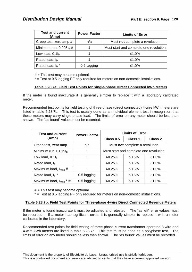
Distribution Design Manual Part B, section 6, Page
This document is the property of Electricité du Laos. Unauthorised use is strictly forbidden. This is a controlled document and users are advised to verify that they have a current approved version.
120
Test and current (Amp)
Power Factor Limits of Error
Creep test, zero amp # n/a Must not complete a revolution
Minimum run, 0.005Ib # 1 Must start and complete one revolution
Low load, 0.1Ib 1 61.0%
Rated load, Ib 1 61.0%
Rated load, Ib * 0.5 lagging 61.0%
# = This test may become optional. * = Test at 0.5 lagging PF only required for meters on non-domestic installations.
Table 6.28.7a: Field Test Points for Single-phase Direct Connected kWh Meters
If the meter is found inaccurate it is generally simpler to replace it with a laboratory calibrated meter. Recommended test points for field testing of three-phase (direct connected) 4-wire kWh meters are listed in table 6.28.7b. This test is usually done as an individual element test in recognition that these meters may carry single-phase load. The limits of error on any meter should be less than shown. The “as found” values must be recorded.
Limits of Error Test and current (Amp)
Power Factor Class 0.5 Class 1 Class 2
Creep test, zero amp n/a Must not complete a revolution
Minimum run, 0.015Ib 1 Must start and complete one revolution
Low load, 0.1Ib 1 60.25% 60.5% 61.0%
Rated load, Ib 1 60.25% 60.5% 61.0%
Maximum load, Imax # 1 60.25% 60.5% 61.0%
Rated load, Ib * 0.5 lagging 60.25% 60.5% 61.0%
Maximum load, Imax * # 0.5 lagging 60.25% 60.5% 61.0%
# = This test may become optional. * = Test at 0.5 lagging PF only required for meters on non-domestic installations.
Table 6.28.7b: Field Test Points for Three-phase 4-wire Direct Connected Revenue Meters
If the meter is found inaccurate it must be adjusted and retested. The “as left” error values must be recorded. If a meter has significant errors it is generally simpler to replace it with a meter calibrated in the laboratory. Recommended test points for field testing of three-phase current transformer operated 3-wire and 4-wire kWh meters are listed in table 6.28.7c. This test must be done as a polyphase test. The limits of error on any meter should be less than shown. The “as found” values must be recorded.
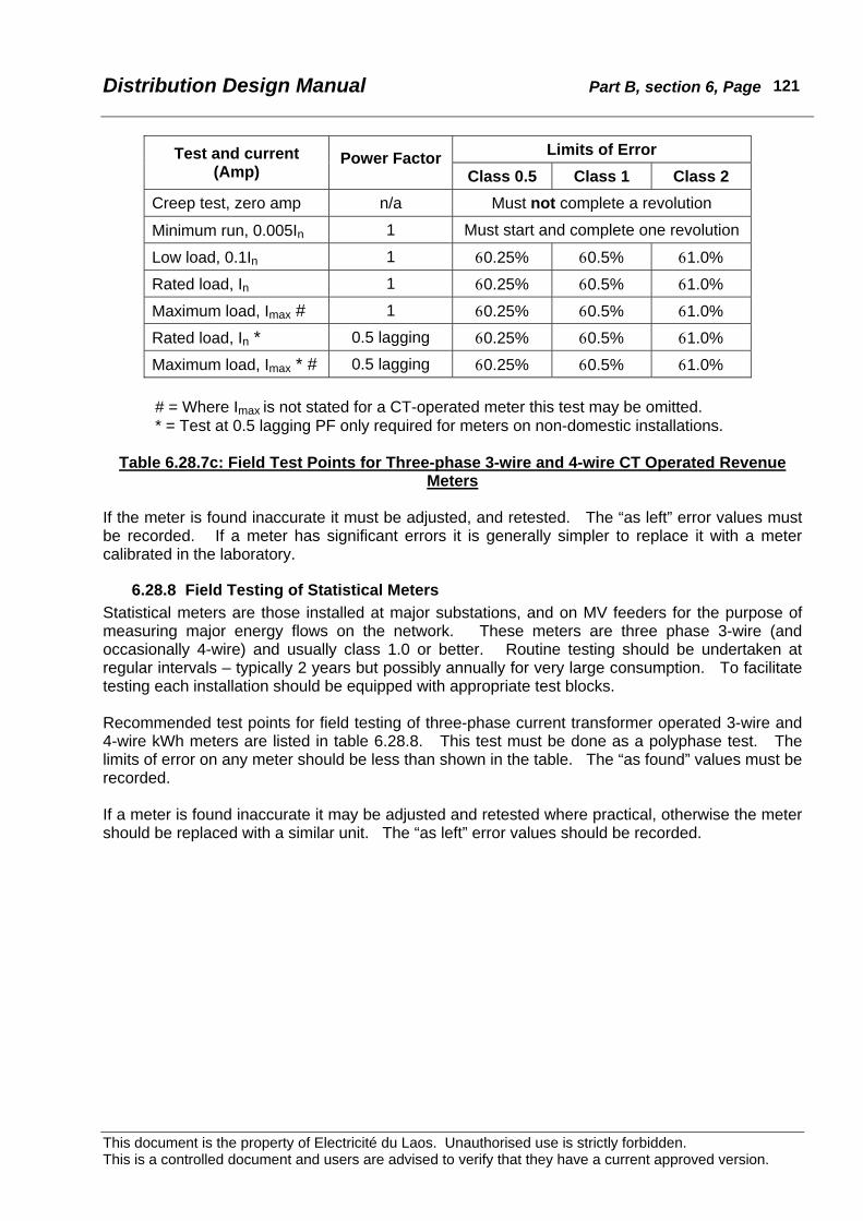
Distribution Design Manual Part B, section 6, Page
This document is the property of Electricité du Laos. Unauthorised use is strictly forbidden. This is a controlled document and users are advised to verify that they have a current approved version.
121
Limits of Error Test and current (Amp)
Power Factor Class 0.5 Class 1 Class 2
Creep test, zero amp n/a Must not complete a revolution
Minimum run, 0.005In 1 Must start and complete one revolution
Low load, 0.1In 1 60.25% 60.5% 61.0%
Rated load, In 1 60.25% 60.5% 61.0%
Maximum load, Imax # 1 60.25% 60.5% 61.0%
Rated load, In * 0.5 lagging 60.25% 60.5% 61.0%
Maximum load, Imax * # 0.5 lagging 60.25% 60.5% 61.0%
# = Where Imax is not stated for a CT-operated meter this test may be omitted. * = Test at 0.5 lagging PF only required for meters on non-domestic installations.
Table 6.28.7c: Field Test Points for Three-phase 3-wire and 4-wire CT Operated Revenue
Meters If the meter is found inaccurate it must be adjusted, and retested. The “as left” error values must be recorded. If a meter has significant errors it is generally simpler to replace it with a meter calibrated in the laboratory.
6.28.8 Field Testing of Statistical Meters Statistical meters are those installed at major substations, and on MV feeders for the purpose of measuring major energy flows on the network. These meters are three phase 3-wire (and occasionally 4-wire) and usually class 1.0 or better. Routine testing should be undertaken at regular intervals – typically 2 years but possibly annually for very large consumption. To facilitate testing each installation should be equipped with appropriate test blocks. Recommended test points for field testing of three-phase current transformer operated 3-wire and 4-wire kWh meters are listed in table 6.28.8. This test must be done as a polyphase test. The limits of error on any meter should be less than shown in the table. The “as found” values must be recorded. If a meter is found inaccurate it may be adjusted and retested where practical, otherwise the meter should be replaced with a similar unit. The “as left” error values should be recorded.

Distribution Design Manual Part B, section 6, Page
This document is the property of Electricité du Laos. Unauthorised use is strictly forbidden. This is a controlled document and users are advised to verify that they have a current approved version.
122
Limits of Error Test and current (Amp) Power Factor
Class 0.5 Class 1 Creep test, zero amp n/a Must not complete a revolution
Minimum run, 0.005In 1 Must start and complete one revolution
Low load, 0.1In 1 60.25% 60.5%
Rated load, In 1 60.25% 60.5%
Maximum load, Imax # 1 60.25% 60.5%
Rated load, In 0.5 lagging 60.25% 60.5%
Maximum load, Imax # 0.5 lagging 60.25% 60.5% # = Where Imax is not stated for a CT-operated meter this test may be omitted. Table 6.28.8: Field Tests for Three-phase 3-wire and 4-wire Statistical Meters