5th oxyfuel combustion research network meeting presentations...prof. dr. techn. g. scheffknecht...
TRANSCRIPT

Prof. Dr. techn. G. Scheffknecht
Institut für Feuerungs- und Kraftwerkstechnik
Acid Gas Control by Dry Sorbent Injection in Air and Oxy-Fuel
Combustion
5th Oxyfuel Combustion Research Network Meeting
Hongyi Hotel, Wuhan, China
27th/30th October 2015
byReinhold Spörl, Stefan Pek, Siqiang Qin,
Jörg Maier, Günter Scheffknecht
Contacts:[email protected]@ifk.uni-stuttgart.de

2
Outline
1. Introduction
2. Motivation
3. Methodology
4. Experimental results
5. Summary and outlook

Acid gases in oxy-fuel combustion
3
• Air-fired combustion:
fuel& air
N2
Combustion products:CO2, H2O, SO2, HCl, etc.

Acid gases in oxy-fuel combustion
4
• Oxy-fuel combustion:
fuel& O2 Combustion products:
CO2, H2O, SO2, HCl, etc.
Exclusion of airborne N2:• Generation of CO2 rich gas
for sequestration/utilization• Increase of acid gas
concentrations (factor 4-5)

Acid gases in oxy-fuel recycle combustion
5
• Oxy-fuel recycle combustion:
fuel& O2
CO2-richflue gas
Flue gas recirculation to control:• Temperatures• Gas flows
HEAT TRANSFER

Acid gases in oxy-fuel recycle combustion
6
• No recycle:
• Recycle combustion: Acid gases (SO2, HCl):
• Recycle combustion does not alter gas concentrations

Acid gas removal in recycle combustion
7
• No recycle:
• Recycle combustion: Acid gases (SO2, HCl):
Performance gainby recirculation
Recycle ratio: 70%

Acid gas removal within recycle
Dry Sorbent Injection (DSI) [e.g. CaCO3 or Ca(OH)2]:reactions, e.g.: CaCO3 + SO2 + ⁄1 2 O2 → CaSO4
8
Benefits/drawbacks: - Low costs (no scrubber required)- No excessive gas cooling- Contamination of ash

9
Outline
1. Introduction
2. Motivation
3. Methodology
4. Experimental results
5. Summary and outlook

Motivation
Open Questions: Impact of oxy-fuel conditions on DSI performance: High impurity levels (e.g.: SOx, HCl)
High CO2 levels
Changed temperature profile
Flue gas recirculation
Goal of this study: Identify limitations of DSI technology
Demonstrate DSI applicability/performance under oxy conditions
10

11
Outline
1. Introduction
2. Motivation
3. Methodology
4. Experimental results
5. Summary and outlook

12
20kW Electrically Heated Combustion Test Rig
Sorbent injection locations:• In-furnace (~ 1100°C)• Low temperature (~ 220 °C)
Combustion conditions:• Tfurnace:1350°C -1100°C• λ ≈ 1.1-1.15• ��𝑉flue gas = 11.5 m3(STP)/h
Gas sampling: • End of furnace• After filter

13
Combustion conditions
Air (reference) Simulated oxy-fuel:
• 28 vol% O2
• Partial recycle cleaning: 50% SO2, 100% HCl & 20% H2O capture in recycle
Simulaterecycle

14
Sorbent injection
• Feeder has a venturi dispersion system
• Injection with approx. 1.2 m3(STP)/h gas
• Loss in weight recorded
• Feeding Ca(OH)2 with CO2 is problematic:
Ca OH 2 + CO2 → CaCO3 + H2O
Sorbent gets sticky, blocks pipes/venturi
20kW oxy tests carried out with N2 carrier gas
CaCO3 dosing with CO2 was successfully tested at IFK’s 500 kW test rig

15
SO2, SO3 & HCl measurement techniques
• SO2: Continuous NDIR analyser ABB EL3020
• SO3: Discontinuous wet chemical measurement (controlled condensation: triplet measurements)
• Good agreement to wet chemical measurement method:US2.5 coal wood pellets torr. straw
HClwet chem. 207 8 19
FTIR 226 7 20
• HCl: Continuous FTIR analyser GASMET DX4000 allows investigation of time resolved behaviour:

16
Fuel and Sorbents
• Fuel for DSI tests: high S and Cl US coalNCV H2O Ash V Cfix C S H N Cl O
[MJ/kg, raw] [%, raw] [%, wf] [%, waf] [%, waf] [%, waf] [%, waf] [%, waf] [%, waf] [%, waf] [%, waf]
US2.5 30.5 1.6 9.43 38.7 61.3 81.9 2.67 5.2 1.6 0.30 8.33
• Sorbents: Different hydrated limes (Ca(OH)2): Sorbacal A, H, SP, SPS [by Lhoist]
Finely milled limestone (CaCO3) [by Lhoist]
Na-based sorbent: Trona [milled & sieved < 32µm]
Sample type Unit Fine limestone 45μm (Germany)
Sorbacal® A (Germany)
Sorbacal® H (Spain)
Sorbacal®SP(France)
Sorbacal®SPS(France)
CaCO3 [%] 98,3 4,1 3,2 4,1 6,4CaO available [%] 0,2 69,2 70,3 72,2 70,6Ca(OH)2 [%] 0,3 91,4 92,9 95,4 93,3TOTAL [CaCO3 + Ca(OH)2] [%] 98,5 95,6 96,0 99,5 99,6Laser PSD - d90 [μm] 24,2 7,2 15,2 39,3 39,3Specific Surface Area BET [m²/g] 2 35 16 41 32Total Porous Volume BJH (17-1000Å) [cm³/g] 0,005 0,086 0,080 0,209 0,186

17
Normalized stoichiometric ratios & DSI performance
• Injection stoichiometry determines acid gas removal efficiency:(i.e.: How many moles of sorbent per mole of SO2/SO3/HCl are injected?)
CaS
=�msorbentWsorbent
ySO2× �VFGVmol
; Ca2Cl
=�msorbentWsorbent
2×yHCl× �VFGVmol
; NaCl
=�msorbentWsorbent
yHCl× �VFGVmol
;
Where:msorbent= mass flow sorbent [g/h], Wsorbent= mol. weight sorbent [g/mol], ySO2= SO2 conc. [ppm],
y𝐻𝐻𝐶𝐶𝐶𝐶= HCl conc. [ppm], 𝑉𝑉𝐹𝐹𝐹𝐹= flue gas flowrate [m3 (STP)/h], 𝑉𝑉𝑚𝑚𝑚𝑚𝐶𝐶= molar volume [m3 (STP)/mol].
• Percentaged acid gas removal: η𝑖𝑖
η𝑖𝑖 =y𝑖𝑖0 − y𝑖𝑖sorbent
y𝑖𝑖0× 100%
Where:y𝑖𝑖0= conc. of component
i without sorbentinjection,
y𝑖𝑖sorbent= equilibrated conc. ofcomponent i duringsorbent injection,
𝑖𝑖= acid gas component: SO2, SO3, HCl.

18
Outline
1. Introduction
2. Motivation
3. Methodology
4. Experimental results
5. Summary and outlook

19
Results: Example of DSI test
Air-fired, in-furnace injection of SPS
Explanation: D dosing gas on; S sorbent on;I injection increased; F filter cleaning
20
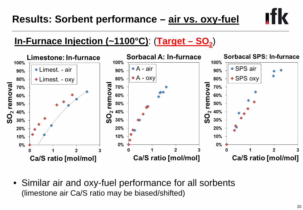
Results: Sorbent performance – air vs. oxy-fuel
In-Furnace Injection (~1100°C): (Target – SO2)
• Similar air and oxy-fuel performance for all sorbents (limestone air Ca/S ratio may be biased/shifted)

21
Results: Sorbent performance – air vs. oxy-fuel
In-Furnace Injection (~1100°C): (Target – SO2, Co-benefit: HCl)
• HCl capture less efficient for in-furnace injection & better in air-firing (at high SO2: sorbent consumed by SO2 before it can react with HCl)
• Requires excess sorbent to show an effect on HCl (esp.: limestone)

22
Results: Sorbent performance – air vs. oxy-fuel
Injection upstream filter: (Target: HCl)
• Very similar air and oxy-fuel performance
• Very efficient HCl removal with SP and SPS

23
Results: Sorbent performance – air vs. oxy-fuel
Injection upstream filter: (Target: HCl, Co-benefit: SO2)
• SO2 capture less efficient in low temperature injection (at low temp.: sorbent consumed by HCl before it can react with SO2)
• Requires excess sorbent to show an effect

24
Results: Sorbent performance – air vs. oxy-fuel
Injection upstream filter: (Target: HCl, Co-benefit: SO2)
• Similar air and oxy-fuel performance • HCl (and SO2) removal efficiency similar to Ca(OH)2
• Reaction behaviour of trona much slower than Ca(OH)2

25
Results: Sorbent performance – SO3 oxy-fuel
Injection into furnace & upstream filter: (Target: SO2 or HCl)
• In-Furnace: At a high SO2 reduction also SO3 capture is good
• Upstream Filter: Also at low HCl reduction, good SO3 capture

26
Outline
1. Introduction
2. Motivation
3. Methodology
4. Experimental results
5. Summary and outlook

27
Summary and outlook
DSI for acid gas control is a highly promising technology for the oxy-fuel recycle process:
• Limitation: - Feeding of Ca(OH)2 with CO2 is problematic - No problems observed with limestone
• No negative impact of oxy-fuel conditions on sorbent performance
• Very high SO3 and HCl removal efficiencies (>90%) possible with low temperature injection at moderate sorbent consumption
• Performance will profit considerably from flue gas recirculation (oxy-fuel recycle tests that were just completed can validate this)
Outlook:• DSI tests at CIUDEN’s 20MW oxy-fuel plant in 2016
• More details on air/oxy-fuel DSI tests will be published in future

Thank you for your attention!
28
ACKNOWLEDGMENTSThe research leading to these results has received funding from the European Union’s ResearchFund for Coal and Steel (RFCS) research programme under grant agreement num. RFCR-CT-2013-00010 (RFCS research project BiOxySorb: http://bioxysorb.eu-projects.de/). The authors gratefullyacknowledge this financial contribution and the support by advices and expertise of the BiOxySorbproject partners Fundación Ciudad de la Energía, E.ON Technologies (Ratcliffe) Ltd., LhoistRecherche et Développement SA and Gestamp Biomass Solutions. The authors also thank thecolleagues of IFK’s department “Firing Systems” who contributed to this work and in particular M.Pagano and M. Faulhaber, as well as W. Ross and his team of IFK’s ´Laboratory for Fuels, Ashesand Slag´ for their support in the performed experiments.
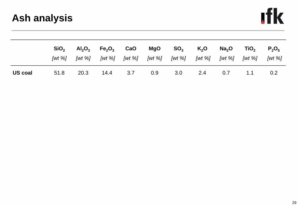
Ash analysis
29
SiO2
[wt %]
Al2O3
[wt %]
Fe2O3
[wt %]
CaO
[wt %]
MgO
[wt %]
SO3
[wt %]
K2O
[wt %]
Na2O
[wt %]
TiO2
[wt %]
P2O5
[wt %]
US coal 51.8 20.3 14.4 3.7 0.9 3.0 2.4 0.7 1.1 0.2

Backup: Controlled condensation method
• No other flue gas component condensing at 100-200°C
• Separation of H2SO4 through selective condensation
• Condenser: Glas coil tempered between water and acid dew point
• Sample train:
• Sample analysis by ion chromatography30
in out
H2SO4 condenser

Backup: SO3 sampling - Ash separation
• At IFK in-stack dust removal is considered to be the most reliable
configuration, to avoid H2SO4 condensation on the filter air ingress
• Possible filter material for in-stack dust removal:
−Quarz wool: quarz fibers consisting of >99% SiO2
31
32
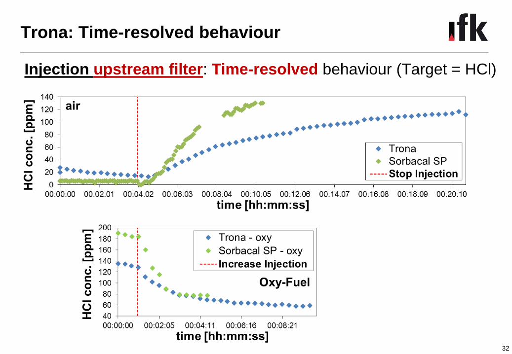
Trona: Time-resolved behaviour
Injection upstream filter: Time-resolved behaviour (Target = HCl)

33
Example of measured concentrations
Air-fired, injection of SPS before filter
Explanation: D dosing gas on; S sorbent on;I injection increased; F filter cleaning