5707 pacific blvd/preliminary... · 2016-10-16 · wire glass wheel chair wood with water...
TRANSCRIPT
M
L
K
J
I
NOTE:
Y
W
H
G
V
U
F
E
T
S
D
R
Q
C
B
A
P
O
N
FIRE EXTINGUISHERF.E.
TERRAZZOTERR.
MAY NOT BE THE SAME AS USEDABBREVIATIONS MAY BE USED, ANDNOT ALL OF THESE ARCHITECTURAL
BY THE OTHER DISCIPLINES.
MULLIONMOUNTINGMOUNTED
MISCELLANEOUS
MOLDINGMODIFIEDMOD.
MLD'G.MTD.MNT'G.MULL.
MISC.
MECHANICAL/ELECTICAL/PLUMBING
MASONRY OPENING
MATERIALMAT.
MILLIMETERMETAL
MINIMUM
MECHANICALMAXIMUM
MTL.
MIN.MM.
M.E.P.MECH.MAX.
MAN HOLEMANUALMANUFACTURERMASONRY
MACHINEM.H.
MAS.MFG'R.MAN.
M.O.
MACH.
HARDWOODHD'WD.
INSIDE DIAMETERI.D.
W.P.
LAVATORYLAV.
POUND
LIGHTWEIGHT
LOW POINTLINEAR FEET
LEFT HAND(ED)LIGHT
LB.L. PT.
LT'WT.L.F.
LT.L.H.
KNOCK OUT
LAMINATE
JOINT
LAM.
K.O.
JT.
W.I.
YD.
INTERIOR
INCLUDEINSULATE
HOSE BIBBHOURINCH
INT.
HR.
INSUL.INCL.IN.
H.B.
HOLLOW COREHOLLOW METALHORIZONTAL
HIGH POINT
HEADHEIGHT
HOR.H.M.H.C.H. PT.HT.HD.
W.
WDW.W.G.
W. CH.
w/WWF.WD.
W.T.W.
W.C.W.H.
W.R.W.P.WT.
T.
GENERAL CONTRACTOR
GALVANIZED IRON
GRAB BARG.B.
GROUND
HANDICAP
GYPSUM BOARDGYPSUM
GRADEGND.
HCP.
GYP. BD.GYP.
GR.
GLASS
GALVANIZED
GENERALGAUGE
G.C.
GL.
GEN.
GALV.
GA.G.I.
V.B.
V.W.C.V.C.T.VERT.
VAR.V.T.R.
TRT'D.TYP.
UR.U.O.N.UNFIN.
FLOOR MOUNTED
FIRE HOSE CABINET
FLOURESCENTFLOUR.
FUTURE
FOOT OR FEETFOOTINGFOUNDATIONFRAMEFURRING
FR.FURR.FUT.
FND.FT'G.FT.
FLOOR DRAINFLOORFLOORING
FIRE EXTINGUISHER CABINET
F.D.FL. MT'D.
F.H.C.FL'G.FL.
F.E.C.
T.O.P.T.O.SL.
T.B.T & GT.O.W.T.O. STL.
T.H.
THK.THRESH.T.T.D.T.P.D.
T.O.C.T.O.B.
WORK POINTWROUGHT IRON
YARD
WEST
WOVEN WIRE FABRIC
WINDOWWIRE GLASS
WHEEL CHAIR
WOOD
WITH
WATER PROOF(ING)
WALL TO WALL
WATER RESISTANTWATER CLOSET
WEIGHT
WALL HUNG
TREAD
VAPOR BARRIER
VINYL COMPOSITION TILEVINYL WALL COVERING
VENT THROUGH ROOFVARIES
VERTICAL
UNLESS OTHERWISE NOTED
TREATEDTYPICALUNFINISHED
URINAL
TOP OF PAVING
TONGUE & GROOVE
TOP OF STEELTOP OF SLAB
TOP OF WALL
TOWEL BARTOWEL HOOK
TOILET PAPER DISPENSERTOILET TISSUE DISPENSER
THICK
TOP OF CURB
THRESHHOLD
TOP OF BEAM
P. BD.
CARPETCPT.
RM.
ELEVATIONELEV.
SPEC.
FACE OF FRAMING
EXPANSION JOINTE.J.
FAN COIL UNITFINISH
EXTERIOR
FACE OF CONCRETE
F.C.U.FIN.
F.O.C.
EXT.
F.O.F.
EXPANSION
ENCLOSUREEQUALEQUIPMENTEXHAUSTEXISTINGEXIST.
EXP.
EXH.EQUIP.EQ.ENCL.
SUSP.
TEL.T.V.TEMP.T.C.
SQ.
S.A.STRUCT.
S.S.STD.STL.
DRINKING FOUNTAIN
ELECTRICELECTRIC PANEL
EACHEAST
ELECT.E.P.
E.EA.
DOORDOUBLEDOWNDOWNSPOUTDRAWERDRAWINGDWG.
D.F.
DWR.DSDN.DBL.DR.
SERV.
S.S.C.S.DSIM.S. & R.SHT.
SECT.SCHED.
S.N.D.R.S.N.D.
R.O.
Q.T.
DEGREE(S)o
DIMENSIONDISPENSER
DEPARTMENTDETAILDIAGONALDIAMETER
DIM.DISP.
DIA. or 0DIAG.DET.DEPT.
DEG. or
CUBICCOUNTERSUNKCONTINUOUSCONTROL JOINTCONSTRUCTIONCONNECTION
CU.
CONN.CONST.C.J.CONT.CSK.
REQ'D.
REV.
R.
R.O.W.
R.D.
R.H.
R.A.
RAD.
REINF.REG.REFL.RE:
CONC. MAS. UNIT
CERAMICCER.
CONCRETE
CORNER GUARDCHANNELCLEAN OUTCOLUMN
CONC.C.M.U.
COL.C.O.CHAN.C.G.
CAST IN PLACECAST IRONCEILINGCEMENTCENTERCENTERLINEC.L.
CTR.CEM.CLG.C.I.C.I.P.
POL.
P.S.I.P.S.F.
PROP.PVC.
QT'Y.
PLY'WD.PT.
PART.PLAS.P. LAM.PL.
BLOCKBLK.
CABINET
BUILDINGBUILT UP ROOF
BRACKETBOARD
CAB.
BD.BRKT.
B.U.R.BLDG.
ATTENUATIONASSEMBLY
BETWEENBITUMINOUS
AT
BEAM
BIT.
ASSY.ATT.@
BET.BM.
O.F.O. I.
PNT.
P.T.D.
P.T.D.R.
PR.
O.F.C.I.
OPP. H.
O.H.O.D.OA.
ABOVE FINISHED FLOOR
ADJUSTABLEADJ.
ASPHALTARCHITECTURALANODIZEDAPPROXIMATEALUMINUMALTERNATE
ASPH.
ALT.ALUM.APPROX.ANOD.ARCH.
ACCESS DOORACCESS PANELACOUSTICALACOUST.
A.P.A.D.
A.F.F.
N.I.C.N.T.S.NO. or #
OPP.OPN'G.O.C.
N.N/A
NOM.NAT.
PARTICLE BOARD
ROOM
SPECIFICATION
SUSPEND(ED)
TERRA COTTATEMPERATURETELEVISIONTELEPHONE
STAINLESS STEELSQUARE
SUPPLY AIRSTRUCTURALSTEELSTANDARD
SERVICE
SOAP DISPENSER
SHELF & RODSIMILAR
SOLID CORESOUTH
SHEET
SANITARY NAPKIN DISP.SANITARY NAPKIN DISPOSAL& RECEPTACLE
ROUGH OPENING
SCHEDULESECTION
QUARRY TILE
REQUIRED
REVISED or REVISIONRIGHT OF WAYRIGHT HAND(ED)
ROOF DRAINRISER
RETURN AIR
REFER or REFERENCE
RADIUS
REFLECTEDREGISTERREINFORCED
POLISHEDLB. PER SQ. FOOTLB. PER SQ. INCHPOLYVINYL CHLORIDEPROPERTY
QUANTITY
PLASTIC LAMINATE
POINTPLYWOODPLATE
PLASTERPARTITION
OWNER FURNISHED AND
PAPER TOWEL DISPENSERPAPER TOWEL DISPENSER & RECEPTACLE
INSTALLED
PAIRPAINT
OWNER FURNISHED,CONTRACTOR INSTALLED
OPPOSITE HAND
OUTSIDE DIAMETEROVERALL
OVERHEAD
NOT TO SCALENOT IN CONTRACT
OPENINGOPPOSITE
ON CENTER
NUMBER
NOT APPLICABLENORTHNOMINALNATURAL
M.R. MOISTURE RESISTANT
DEMOLISHDEMO.
CERAMIC TILEC.T.
LIMITS OF WORKL.O.W.
FIRE EXTINGUISHER BRACKETF.E.B.
ABBREVIATIONS
• Eroded sediments and other pollutants must be retained on site and may not betransported from the site via sheet flow, swales, area drains, natural drainage coursesor wind.
• Stockpiles of earth and other construction related materials must be protected frombeing transported from the site by the forces of wind or water.
• Fuels, oils, solvents and other toxic materials must be stored in accordance with theirlisting and are not to contaminate the soil and surface waters. All approved storagecontainers are to be protected from the weather. Spills may not be washed into thedrainage system.
• Excess or waste concrete may not be washed into the public way or any other drainagesystem. Provisions must be made to retain concrete wastes on site until they can bedisposed of as a solid waste.
• Trash and construction related wastes must be deposited into a covered receptacle toprevent contamination of rainwater and dispersal by wind.
• Sediments and other material may not be traced from the site by vehicle traffic. Theconstruction entrance roadways must be stabilized so as to inhibit sediments frombeing deposited into the public way. Accidental depositions must be swept upimmediately and may not be washed down by rain or other means.
• Any slopes with disturbed soils or demanded of vegetation must be stabilized so as toinhibit erosion by wind and water.
BEST MANAGEMENT PRACTICE
CODE COMPLIANCEGOVERNING AGENCY:City of Huntington Park6550 Miles AvenueHuntington Park, CA 90255APPLICABLE CODES:ALL WORK AND MATERIAL SHALL BE PERFORMED AND INSTALLED IN COMPLIANCE WITH THE CURRENT EDITIONS OF THE FOLLOWING CODES AS ADOPTED BY THE LOCAL GOVERNING AUTHORITIES. NOTHING IN THESE PLANS IS TO BE CONSTRUCTED TO PERMIT WORK NOT CONFORMING TO THESE CODES.
• 2013 CALIFORNIA BUILDING STANDARDS CODE• 2013 CALIFORNIA MECHANICAL CODE• 2013 CALIFORNIA PLUMBING CODE• 2013 CALIFORNIA ELECTRICAL CODE• 2013 CALIFORNIA ENERGY CODE• COUNTY OF HUNTINGTON PARK MUNICIPAL CODE AND ADOPTING ORDINANCES• BEST MANAGEMENT PRACTICES LISTED ON THIS PROJECT.
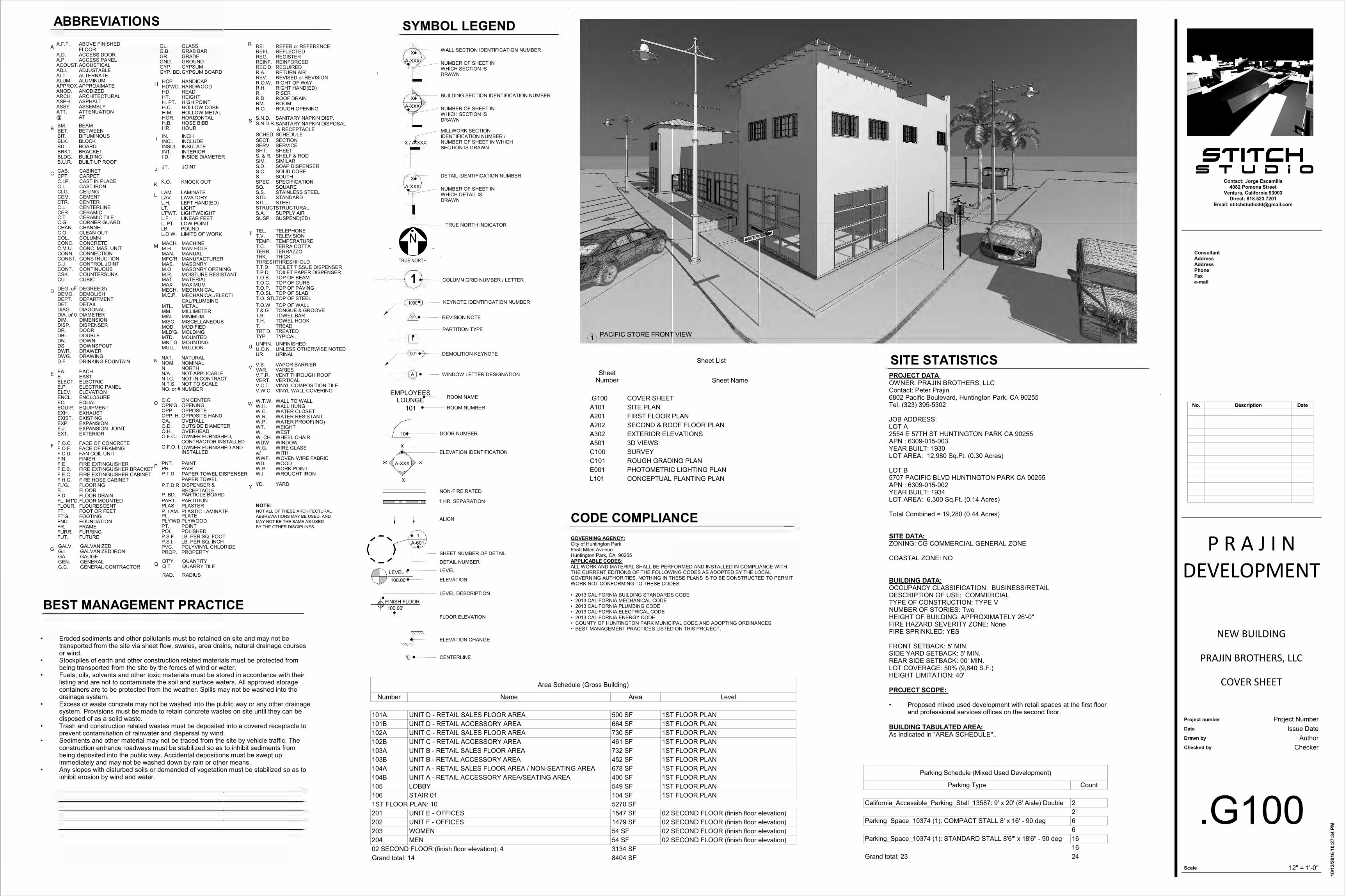
PROJECT DATA OWNER: PRAJIN BROTHERS, LLCContact: Peter Prajin6802 Pacific Boulevard, Huntington Park, CA 90255Tel. (323) 395-5302
JOB ADDRESS: LOT A2554 E 57TH ST HUNTINGTON PARK CA 90255APN : 6309-015-003YEAR BUILT: 1930 LOT AREA: 12,980 Sq.Ft. (0.30 Acres)
LOT B5707 PACIFIC BLVD HUNTINGTON PARK CA 90255APN : 6309-015-002YEAR BUILT: 1934 LOT AREA: 6,300 Sq.Ft. (0.14 Acres)
Total Combined = 19,280 (0.44 Acres)
SITE DATA: ZONING: CG COMMERCIAL GENERAL ZONE
COASTAL ZONE: NO
BUILDING DATA:OCCUPANCY CLASSIFICATION: BUSINESS/RETAILDESCRIPTION OF USE: COMMERCIALTYPE OF CONSTRUCTION: TYPE V NUMBER OF STORIES: TwoHEIGHT OF BUILDING: APPROXIMATELY 26'-0"FIRE HAZARD SEVERITY ZONE: NoneFIRE SPRINKLED: YES
FRONT SETBACK: 5' MIN.SIDE YARD SETBACK: 5' MIN.REAR SIDE SETBACK: 00' MIN.LOT COVERAGE: 50% (9,640 S.F.)HEIGHT LIMITATION: 40'
PROJECT SCOPE:
• Proposed mixed used development with retail spaces at the first floorand professional services offices on the second floor.
BUILDING TABULATED AREA: As indicated in "AREA SCHEDULE"..
SITE STATISTICS
1
1
KEYNOTE IDENTIFICATION NUMBER
WINDOW LETTER DESIGNATION
DEMOLITION KEYNOTE
PARTITION TYPE
REVISION NOTE
COLUMN GRID NUMBER / LETTER
WALL SECTION IDENTIFICATION NUMBER
NUMBER OF SHEET IN WHICH SECTION IS DRAWN
XA-XXX
2
A
1000
001
NTRUE NORTH
TRUE NORTH INDICATOR
X / A-XXX
MILLWORK SECTION IDENTIFICATION NUMBER / NUMBER OF SHEET IN WHICH SECTION IS DRAWN
BUILDING SECTION IDENTIFICATION NUMBER
NUMBER OF SHEET IN WHICH SECTION IS DRAWN
XA-XXX
DETAIL IDENTIFICATION NUMBER
NUMBER OF SHEET IN WHICH DETAIL IS DRAWN
XA-XXX
SYMBOL LEGEND
101
EMPLOYEES LOUNGE
101
CENTERLINE
ELEVATION CHANGE
ELEVATION IDENTIFICATION
LEVEL DESCRIPTION
FLOOR ELEVATION
ELEVATION
NON-FIRE RATED
DOOR NUMBER
ROOM NAME
ROOM NUMBER
X X
X
X
FINISH FLOOR100.00'
1 HR. SEPARATION
SHEET NUMBER OF DETAIL
DETAIL NUMBER
1
100.00'
LC
ALIGN
A-601
A-XXX
LEVELLEVEL 1
Stitch
Scale
Project number
Date
Drawn by
Checked by
Contact: Jorge Escamilla4082 Pomona Street
Ventura, California 93003Direct: 818.523.7201
Email: [email protected]
ConsultantAddressAddressPhoneFaxe-mail
S t u d i o
12" = 1'-0"
10/1
3/20
16 1
0:27
:34
PM
.G100
COVER SHEET
Project Number
NEW BUILDING
P R A J I NDEVELOPMENT
Issue DateAuthor
Checker
PRAJIN BROTHERS, LLC
Sheet List
SheetNumber Sheet Name
.G100 COVER SHEETA101 SITE PLANA201 FIRST FLOOR PLANA202 SECOND & ROOF FLOOR PLANA302 EXTERIOR ELEVATIONSA501 3D VIEWSC100 SURVEYC101 ROUGH GRADING PLANE001 PHOTOMETRIC LIGHTING PLANL101 CONCEPTUAL PLANTING PLAN
1 PACIFIC STORE FRONT VIEW
Area Schedule (Gross Building)
Number Name Area Level
101A UNIT D - RETAIL SALES FLOOR AREA 500 SF 1ST FLOOR PLAN101B UNIT D - RETAIL ACCESSORY AREA 664 SF 1ST FLOOR PLAN102A UNIT C - RETAIL SALES FLOOR AREA 730 SF 1ST FLOOR PLAN102B UNIT C - RETAIL ACCESSORY AREA 461 SF 1ST FLOOR PLAN103A UNIT B - RETAIL SALES FLOOR AREA 732 SF 1ST FLOOR PLAN103B UNIT B - RETAIL ACCESSORY AREA 452 SF 1ST FLOOR PLAN104A UNIT A - RETAIL SALES FLOOR AREA / NON-SEATING AREA 678 SF 1ST FLOOR PLAN104B UNIT A - RETAIL ACCESSORY AREA/SEATING AREA 400 SF 1ST FLOOR PLAN105 LOBBY 549 SF 1ST FLOOR PLAN106 STAIR 01 104 SF 1ST FLOOR PLAN1ST FLOOR PLAN: 10 5270 SF201 UNIT E - OFFICES 1547 SF 02 SECOND FLOOR (finish floor elevation)202 UNIT F - OFFICES 1479 SF 02 SECOND FLOOR (finish floor elevation)203 WOMEN 54 SF 02 SECOND FLOOR (finish floor elevation)204 MEN 54 SF 02 SECOND FLOOR (finish floor elevation)02 SECOND FLOOR (finish floor elevation): 4 3134 SFGrand total: 14 8404 SF
No. Description Date
Parking Schedule (Mixed Used Development)
Parking Type Count
California_Accessible_Parking_Stall_13587: 9' x 20' (8' Aisle) Double 22
Parking_Space_10374 (1): COMPACT STALL 8' x 16' - 90 deg 66
Parking_Space_10374 (1): STANDARD STALL 8'6"' x 18'6" - 90 deg 1616
Grand total: 23 24
57th
PAC
IFIC
BLV
D.
90° 00' 00"140.00'
N W
0° 0
0' 0
0"80
.00'
NE
90° 00' 00"140.00'
N E
0° 0
0' 0
0"45
.00'
SW
90° 00' 00"140.00'
N W
12' - 0" 86' - 5" 48' - 8" 5' - 0" 6' - 2"
PROPOSED NEW
BUILDING
1
2
(E) A
LLEY
(E) ALLEY
13
14
15
16
17
18
19
20
21
22
23
5' -
0"20
' - 0
"75
' - 1
"20
' - 0
"5'
- 0"
0° 0
0' 0
0"45
.00'
NE
0° 0
0' 0
0"80
.00'
SW
02
03
04
05
06
07
08
09
10
1112
01
PLANTER PLANTER
PLANTERPLANTERPLANTER
PLA
NTE
RP
LAN
TER
PLA
NTE
R
PLA
NTE
RP
LAN
TER
PLA
NTE
R/ F
UTU
RE
PU
BLI
C A
RT
5' - 0" 18' - 6" 24' - 0" 16' - 0"
3
4
5
6
7
4
8
typ.
9 typ.
EQEQ
EQEQ
EQ
10
60' - 0"
30' -
0"
FUTU
RE
LO
AD
ING
ZO
NE
AR
EA
FUTURE TRASH
ENCLOSURE
25' -
0"
1' -
6"93
' - 6
"5'
- 0"
24
18' - 6" 20' - 4" 48' - 8" 5' - 0"
12' - 9"
5' -
0"40
' - 0
"35
' - 0
"40
' - 0
"5'
- 0"
12' -
0"
3
11
12
TRUE
13
Stitch
Scale
Project number
Date
Drawn by
Checked by
Contact: Jorge Escamilla4082 Pomona Street
Ventura, California 93003Direct: 818.523.7201
Email: [email protected]
ConsultantAddressAddressPhoneFaxe-mail
S t u d i o
1/8" = 1'-0"
10/1
3/20
16 1
0:27
:39
PM
A101
SITE PLAN
Project Number
NEW BUILDING
P R A J I NDEVELOPMENT
Issue DateAuthor
Checker
PRAJIN BROTHERS, LLC
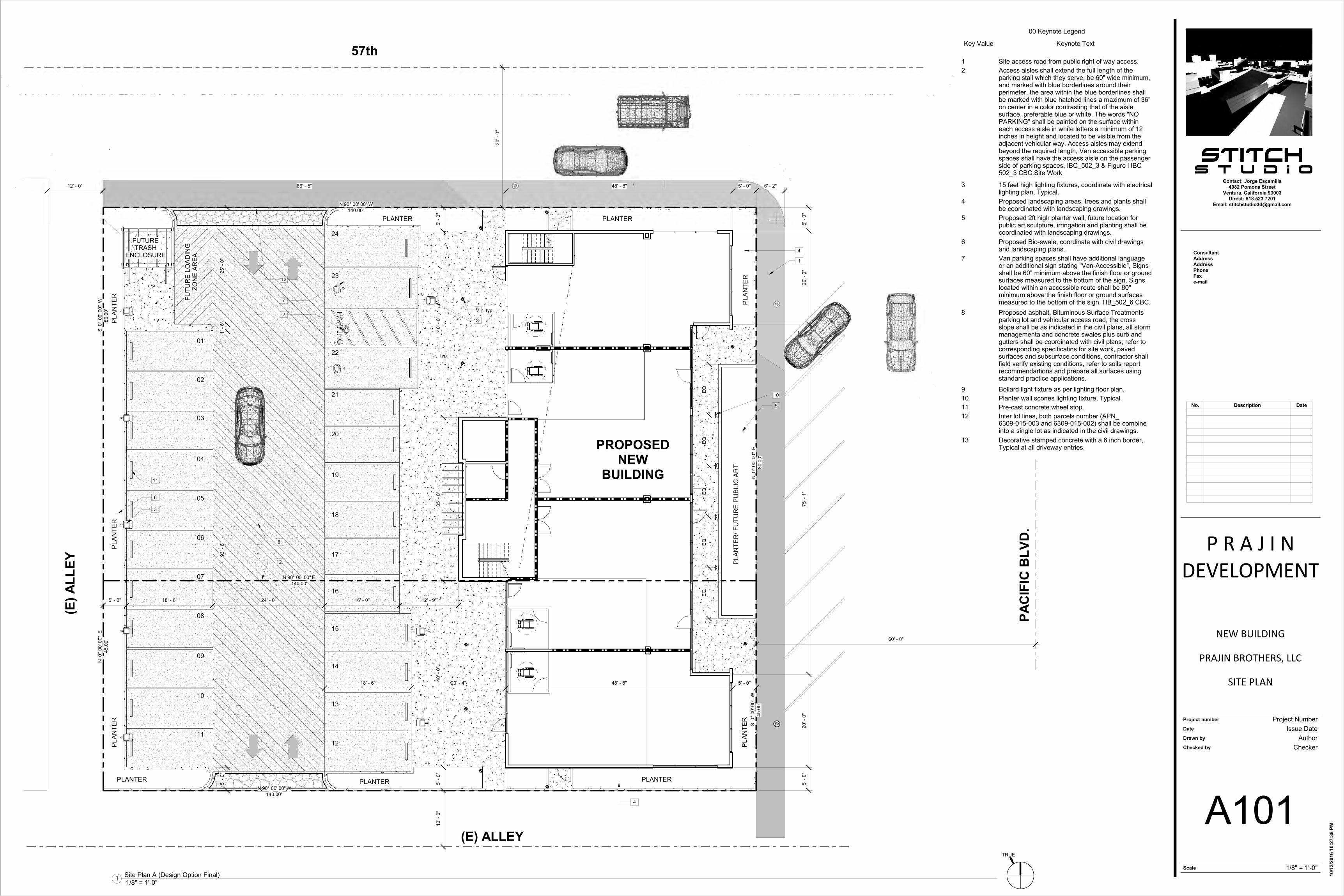
1/8" = 1'-0"1 Site Plan A (Design Option Final)
00 Keynote Legend
Key Value Keynote Text
1 Site access road from public right of way access.2 Access aisles shall extend the full length of the
parking stall which they serve, be 60" wide minimum,and marked with blue borderlines around theirperimeter, the area within the blue borderlines shallbe marked with blue hatched lines a maximum of 36"on center in a color contrasting that of the aislesurface, preferable blue or white. The words "NOPARKING" shall be painted on the surface withineach access aisle in white letters a minimum of 12inches in height and located to be visible from theadjacent vehicular way, Access aisles may extendbeyond the required length, Van accessible parkingspaces shall have the access aisle on the passengerside of parking spaces, IBC_502_3 & Figure l IBC502_3 CBC.Site Work
3 15 feet high lighting fixtures, coordinate with electricallighting plan, Typical.
4 Proposed landscaping areas, trees and plants shallbe coordinated with landscaping drawings.
5 Proposed 2ft high planter wall, future location forpublic art sculpture, irringation and planting shall becoordinated with landscaping drawings.
6 Proposed Bio-swale, coordinate with civil drawingsand landscaping plans.
7 Van parking spaces shall have additional languageor an additional sign stating "Van-Accessible", Signsshall be 60" minimum above the finish floor or groundsurfaces measured to the bottom of the sign, Signslocated within an accessible route shall be 80"minimum above the finish floor or ground surfacesmeasured to the bottom of the sign, l lB_502_6 CBC.
8 Proposed asphalt, Bituminous Surface Treatmentsparking lot and vehicular access road, the crossslope shall be as indicated in the civil plans, all stormmanagementa and concrete swales plus curb andgutters shall be coordinated with civil plans, refer tocorresponding specificatins for site work, pavedsurfaces and subsurface conditions, contractor shallfield verify existing conditions, refer to soils reportrecommendartions and prepare all surfaces usingstandard practice applications.
9 Bollard light fixture as per lighting floor plan.10 Planter wall scones lighting fixture, Typical.11 Pre-cast concrete wheel stop.12 Inter lot lines, both parcels number (APN_
6309-015-003 and 6309-015-002) shall be combineinto a single lot as indicated in the civil drawings.
13 Decorative stamped concrete with a 6 inch border,Typical at all driveway entries.
No. Description Date
A302
3
A302 4
A
020304
10' - 0" 21' - 6"
01
58' - 6" 1"
400 SF
UNIT D - RETAILSALES AREA
104A
63 SF
MECH.106
353 SF
LOBBY105
689 SF
UNIT C - RETAILSALES AREA
103A
81 SF
ELEVATOR107
90 SF
STAIR 01108
694 SF
UNIT B - RETAILSALES AREA
102A
400 SF
UNIT A - SEATINGAREA/SALES
AREA101A
64 SF
UNIT BRESTROOM
102C
2
3
4
6
7
70 SF
UNIT CRESTROOM
103C
70 SF
UNIT DRESTROOM
104C
64 SF
UNIT DRESTROOM
101CB
C
D
E
F
G
19' -
8"
17' -
7"
17' -
6"
19' -
10"
20' -
3"
74' -
6"
20' -
2"
115'
- 0"
547 SF
UNIT A - RETAILSTORAGE AREA/
NON-SEATINGAREA101B
365 SF
UNIT B - RETAILSTORAGE AREA
102B
365 SF
UNIT C - RETAILSTORAGE AREA
103B
638 SF
UNIT D - RETAILSTORAGE AREA
104B
=400 SF
34Assembly15/500
=638 SF
2Kitchen200/290
=365 SF
1Accessory300/290
=689 SF
47Assembly15/695
=353 SF
12Gallery30/353
=63 SF
1Mechanical300/63
=694 SF
47Assembly15/694
=365 SF
2Accessory300/365
=547 SF
2Accessory300/375
=400 SF
34Assembly15/500
EXISTING 2 X 4 WOOD STUD WALL (INTERIOR)
PROPOSED 2 X 4 WOOD STUD WALL (INTERIOR)
REMOVE AND DISCARD EXISTING WOOD STUD WALLS.
2 X 6 WOOD STUD WALL (INTERIOR)
2 X 4 WOOD STUD WALL (EXTERIOR)
2 X 4 WOOD STUD WALL (EXTERIOR - 2 SIDE FINISH)
MANSORY WALL (SEE STRUCTURAL)
CIP CONCRETE WALL (SEE STRUCTURAL)
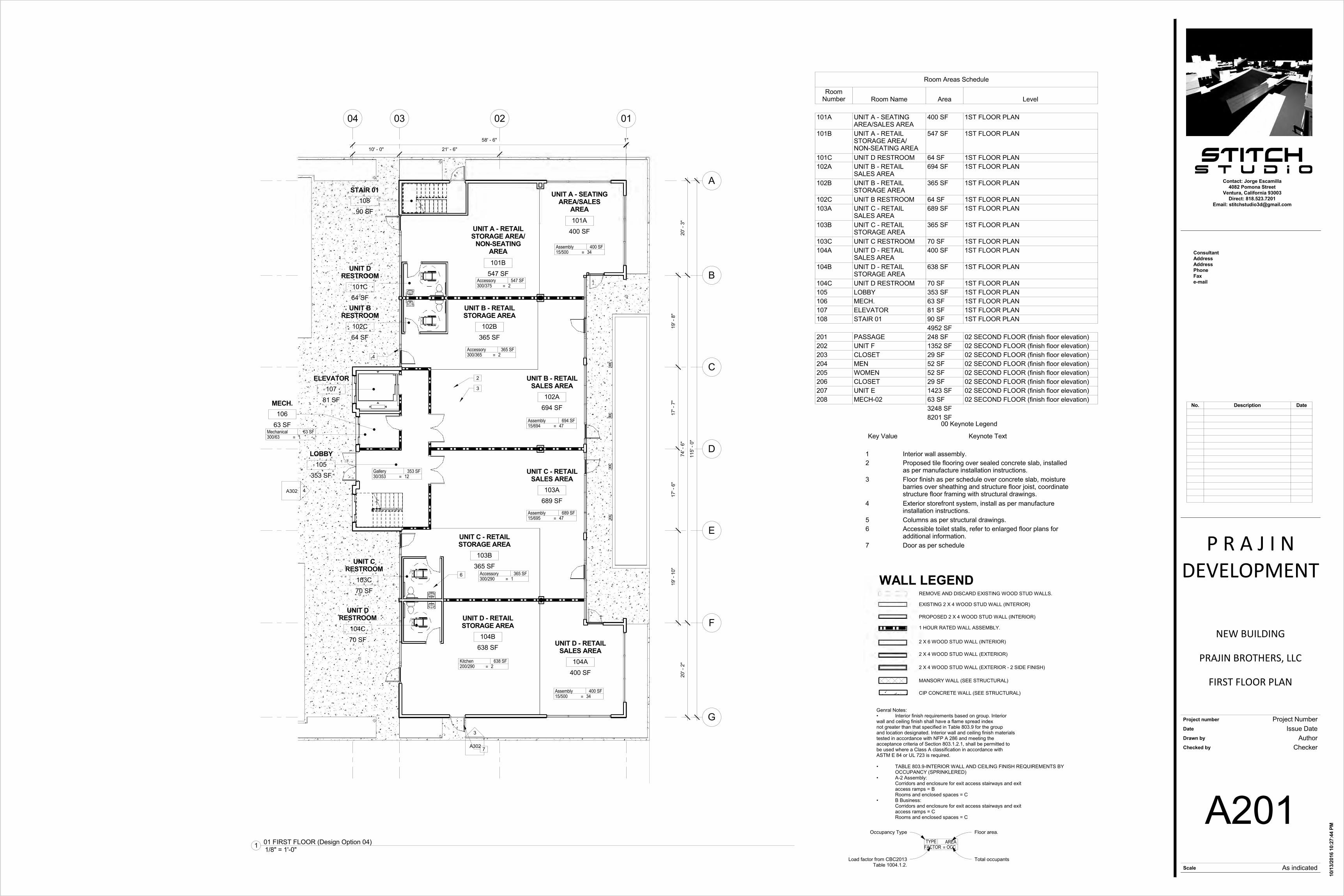
WALL LEGEND
Genral Notes: • Interior finish requirements based on group. Interiorwall and ceiling finish shall have a flame spread indexnot greater than that specified in Table 803.9 for the groupand location designated. Interior wall and ceiling finish materialstested in accordance with NFP A 286 and meeting theacceptance criteria of Section 803.1.2.1, shall be permitted tobe used where a Class A classification in accordance withASTM E 84 or UL 723 is required.
• TABLE 803.9-INTERIOR WALL AND CEILING FINISH REQUIREMENTS BY OCCUPANCY (SPRINKLERED)
• A-2 Assembly: Corridors and enclosure for exit access stairways and exit access ramps = BRooms and enclosed spaces = C
• B Business:Corridors and enclosure for exit access stairways and exit access ramps = CRooms and enclosed spaces = C
1 HOUR RATED WALL ASSEMBLY.
=AREAOCC
TYPEFACTOR
Floor area.
Total occupants
Occupancy Type
Load factor from CBC2013 Table 1004.1.2.
Stitch
Scale
Project number
Date
Drawn by
Checked by
Contact: Jorge Escamilla4082 Pomona Street
Ventura, California 93003Direct: 818.523.7201
Email: [email protected]
ConsultantAddressAddressPhoneFaxe-mail
S t u d i o
As indicated
10/1
3/20
16 1
0:27
:44
PM
A201
FIRST FLOOR PLAN
Project Number
NEW BUILDING
P R A J I NDEVELOPMENT
Issue DateAuthor
Checker
PRAJIN BROTHERS, LLC
1/8" = 1'-0"1 01 FIRST FLOOR (Design Option 04)
00 Keynote Legend
Key Value Keynote Text
1 Interior wall assembly.2 Proposed tile flooring over sealed concrete slab, installed
as per manufacture installation instructions.3 Floor finish as per schedule over concrete slab, moisture
barries over sheathing and structure floor joist, coordinatestructure floor framing with structural drawings.
4 Exterior storefront system, install as per manufactureinstallation instructions.
5 Columns as per structural drawings.6 Accessible toilet stalls, refer to enlarged floor plans for
additional information.7 Door as per schedule
Room Areas Schedule
RoomNumber Room Name Area Level
101A UNIT A - SEATINGAREA/SALES AREA
400 SF 1ST FLOOR PLAN
101B UNIT A - RETAILSTORAGE AREA/NON-SEATING AREA
547 SF 1ST FLOOR PLAN
101C UNIT D RESTROOM 64 SF 1ST FLOOR PLAN102A UNIT B - RETAIL
SALES AREA694 SF 1ST FLOOR PLAN
102B UNIT B - RETAILSTORAGE AREA
365 SF 1ST FLOOR PLAN
102C UNIT B RESTROOM 64 SF 1ST FLOOR PLAN103A UNIT C - RETAIL
SALES AREA689 SF 1ST FLOOR PLAN
103B UNIT C - RETAILSTORAGE AREA
365 SF 1ST FLOOR PLAN
103C UNIT C RESTROOM 70 SF 1ST FLOOR PLAN104A UNIT D - RETAIL
SALES AREA400 SF 1ST FLOOR PLAN
104B UNIT D - RETAILSTORAGE AREA
638 SF 1ST FLOOR PLAN
104C UNIT D RESTROOM 70 SF 1ST FLOOR PLAN105 LOBBY 353 SF 1ST FLOOR PLAN106 MECH. 63 SF 1ST FLOOR PLAN107 ELEVATOR 81 SF 1ST FLOOR PLAN108 STAIR 01 90 SF 1ST FLOOR PLAN
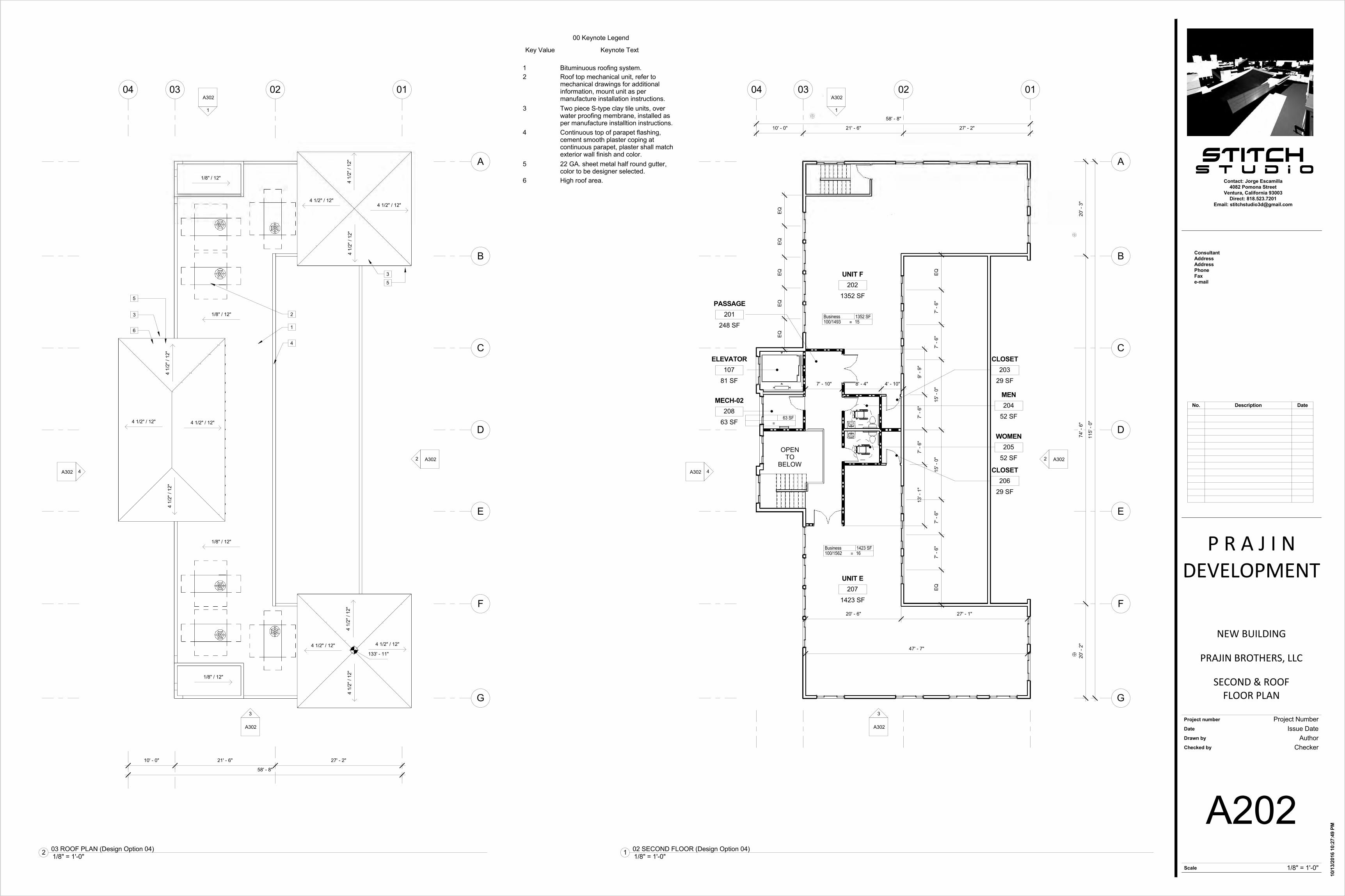
4952 SF201 PASSAGE 248 SF 02 SECOND FLOOR (finish floor elevation)202 UNIT F 1352 SF 02 SECOND FLOOR (finish floor elevation)203 CLOSET 29 SF 02 SECOND FLOOR (finish floor elevation)204 MEN 52 SF 02 SECOND FLOOR (finish floor elevation)205 WOMEN 52 SF 02 SECOND FLOOR (finish floor elevation)206 CLOSET 29 SF 02 SECOND FLOOR (finish floor elevation)207 UNIT E 1423 SF 02 SECOND FLOOR (finish floor elevation)208 MECH-02 63 SF 02 SECOND FLOOR (finish floor elevation)
3248 SF8201 SF
No. Description Date
A302
1
A3022
A302
3
A302 4
A
020304
10' - 0" 21' - 6" 27' - 2"
01
248 SF
PASSAGE201
1352 SF
UNIT F202
1423 SF
UNIT E207
OPEN TO
BELOW
58' - 8"
52 SF
MEN204
52 SF
WOMEN205
B
C
D
E
F
G
63 SF
MECH-02208
7' - 10" 8' - 4" 4' - 10"
13' -
1"
7' -
6"7'
- 6"
9' -
9"
81 SF
ELEVATOR107
EQ7'
- 6"
7' -
6"15
' - 0
"15
' - 0
"7'
- 6"
7' -
6"EQ
EQEQ
EQEQ
EQ
=1423 SF16
Business100/1562
=1352 SF15
Business100/1493
=63 SF
20' -
3"
74' -
6"
20' -
2"
115'
- 0"
20' - 6" 27' - 1"
47' - 7"
29 SF
CLOSET203
29 SF
CLOSET206
A302
1
A3022
A302
3
A302 4
A
020304 01
4 1/
2" /
12"
4 1/2" / 12"
4 1/
2" /
12"
4 1/2" / 12"
4 1/
2" /
12"
4 1/
2" /
12"
4 1/2" / 12"4 1/2" / 12"
1/8" / 12"
1/8" / 12"
10' - 0" 21' - 6" 27' - 2"
58' - 8"
133' - 11"
1
2
3
4
5
4 1/
2" /
12"
4 1/2" / 12" 4 1/2" / 12"
4 1/
2" /
12"
6
3
5
B
C
D
E
F
G
1/8" / 12"
1/8" / 12"
Stitch
Scale
Project number
Date
Drawn by
Checked by
Contact: Jorge Escamilla4082 Pomona Street
Ventura, California 93003Direct: 818.523.7201
Email: [email protected]
ConsultantAddressAddressPhoneFaxe-mail
S t u d i o
1/8" = 1'-0"
10/1
3/20
16 1
0:27
:49
PM
A202
SECOND & ROOFFLOOR PLAN
Project Number
NEW BUILDING
P R A J I NDEVELOPMENT
Issue DateAuthor
Checker
PRAJIN BROTHERS, LLC
1/8" = 1'-0"1 02 SECOND FLOOR (Design Option 04) 1/8" = 1'-0"2 03 ROOF PLAN (Design Option 04)
No. Description Date
00 Keynote Legend
Key Value Keynote Text
1 Bituminuous roofing system.2 Roof top mechanical unit, refer to
mechanical drawings for additionalinformation, mount unit as permanufacture installation instructions.
3 Two piece S-type clay tile units, overwater proofing membrane, installed asper manufacture installtion instructions.
4 Continuous top of parapet flashing,cement smooth plaster coping atcontinuous parapet, plaster shall matchexterior wall finish and color.
5 22 GA. sheet metal half round gutter,color to be designer selected.
6 High roof area.

1ST FLOOR PLAN1' - 0"
02 SECONDFLOOR (finish floor
elevation)15' - 0"
TOP OF ROOFING25' - 0"
02 03 04
2
01
7
5
9
13
1
6
14' -
0"
10' -
0"
10
8
10
1ST FLOOR PLAN1' - 0"
02 SECONDFLOOR (finish floor
elevation)15' - 0"
TOP OF ROOFING25' - 0"
A
9
8
10
6
BCDEFG
8' -
2"10
' - 0
"14
' - 0
"
32' -
2"
26' -
0"
1ST FLOOR PLAN1' - 0"
02 SECONDFLOOR (finish floor
elevation)15' - 0"
TOP OF ROOFING25' - 0"
020304
2
3
01
1
6
7
8
5
1ST FLOOR PLAN1' - 0"
02 SECONDFLOOR (finish floor
elevation)15' - 0"
TOP OF ROOFING25' - 0"
A
1
5
3' -
9"
B C D E F G
1ST FLOOR PLAN1' - 0"
3' -
6"5'
- 10
"
9' -
4"
15
10
16
14
Stitch
Scale
Project number
Date
Drawn by
Checked by
Contact: Jorge Escamilla4082 Pomona Street
Ventura, California 93003Direct: 818.523.7201
Email: [email protected]
ConsultantAddressAddressPhoneFaxe-mail
S t u d i o
As indicated
10/1
3/20
16 1
0:28
:08
PM
A302
EXTERIORELEVATIONS
Project Number
NEW BUILDING
P R A J I NDEVELOPMENT
Issue DateAuthor
Checker
PRAJIN BROTHERS, LLC
00 Keynote Legend
KeyValue Keynote Text
1 15 feet high lighting fixtures, coordinate withelectrical lighting plan, Typical.
2 Concrete side walk.34 Exterior plaster system, smooth trowel finish,
standard color from La Habra Crystal White X50(79) Base 100.
5 Aluminum store-front window system, colorPermafuor Architectural Finish, Redwood,manufacture by Kawneer or of equal grade.
6 Trees as per planting plan, refer to landscapingdrawings.
7 Door as per schedule, color and finish to matchstorefront frame color.
8 One-piece s-shaped barrel clay roof tiles, Redlandclay tiles, Terra Cota Color 2211.
9 Window assembly as per schedule, color to matchRedwood finsh from Kawneer PermafuorArchitectural Finish.
10 Exposed rafter tails, painted as per manufactureinstallation instructions, color Sherwan WilliamsWarm Chestnut - 3114 or of equal grade.
11 Plaster parapet, coping shall be painted white tomatch adjacent wall color.
12 Proposed 2ft high planter wall, future location forpublic art sculpture, irringation and planting shall becoordinated with landscaping drawings.
13 Painted steel gutter and downspout, color darkbrown.
14 Trash enclosure, exterior cement plaster smoothtrowel finish, over CMU block, color and finish tomatch building.
15 Corrugated steel decking, painted grey, fasten to 2xroof members using galvanized self tapping screwsas indicated in structural drawings.
16 Steel tubes, painted standard black paint with lowgloss finish.
17 Painted steel corrugated panel swing doors, allsteel tubing and door hinges shall be painted black.
1/8" = 1'-0"1
EXTERIOR ELEVATION A (DESIGNOPTION 02)
1/8" = 1'-0"2
EXTERIOR ELEVATION B (DESIGNOPTION 02)
1/8" = 1'-0"3
EXTERIOR ELEVATION C (DESIGNOPTION 02)
1/8" = 1'-0"4
EXTERIOR ELEVATION D (DESIGNOPTION 02)
No. Description Date
1/4" = 1'-0"5 TRASH ENCLOSURE ELEVATION
Stitch
Scale
Project number
Date
Drawn by
Checked by
Contact: Jorge Escamilla4082 Pomona Street
Ventura, California 93003Direct: 818.523.7201
Email: [email protected]
ConsultantAddressAddressPhoneFaxe-mail
S t u d i o
10/1
3/20
16 1
0:28
:41
PM
A501
3D VIEWS
Project Number
NEW BUILDING
P R A J I NDEVELOPMENT
Issue DateAuthor
Checker
PRAJIN BROTHERS, LLC
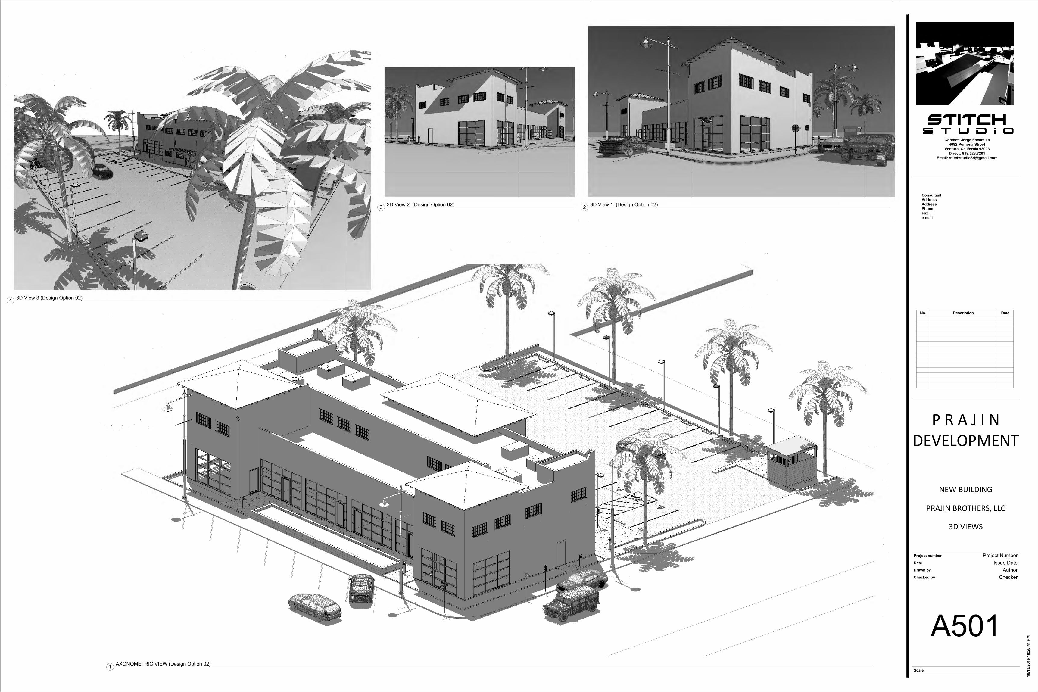
1 AXONOMETRIC VIEW (Design Option 02)
2 3D View 1 (Design Option 02)3 3D View 2 (Design Option 02)
4 3D View 3 (Design Option 02)
No. Description Date
4540 California Avenue, Suite 550Bakersfield, CA 93309P 661.328.6280 F 661.328.6284


UP
57th
PAC
IFIC
BLV
D.
90° 00' 00"140.00'
N W
0° 0
0' 0
0"80
.00'
NE
90° 00' 00"140.00'
N E
0° 0
0' 0
0"45
.00'
SW
90° 00' 00"140.00'
N W
12' - 0" 5' - 1" 20' - 0" 24' - 0" 20' - 0" 17' - 4" 48' - 6" 5' - 1" 6' - 2"
29' -
8"
9' -
0"8'
- 0"
9' -
0" PROPOSEDNEW
BUILDING
1
2
(E) A
LLEY
(E) ALLEY
1314
15
16
17
18
19
20
21
22
23
FUTU
RE
LO
AD
ING
AR
EA
5' -
0"20
' - 0
"75
' - 1
"20
' - 0
"5'
- 0"
0° 0
0' 0
0"45
.00'
NE
0° 0
0' 0
0"80
.00'
SW
02
03
04
05
06
07
08
09
10
11
12
01
PLANTER PLANTER
PLANTERPLANTERPLANTER
PLA
NTE
RP
LAN
TER
PLA
NTE
R
PLA
NTE
RP
LAN
TER
PLA
NTE
R/ F
UTU
RE
PU
BLI
C A
RT
FUTU
RE
TRA
SH
EN
CLO
SU
RE
18' - 6" 24' - 0" 18' - 6" 10' - 3"
3
4
5
6
7
8
9
6
10
typ.
11
typ.
EQ
EQ
EQ
EQ
EQ
12
Scale
Project number
Date
Drawn by
Checked by
Contact: Jorge Escamilla4082 Pomona Street
Ventura, California 93003Direct: 818.523.7201
Email: [email protected]
ConsultantAddressAddressPhoneFaxe-mail
1/8" = 1'-0"
E0.01
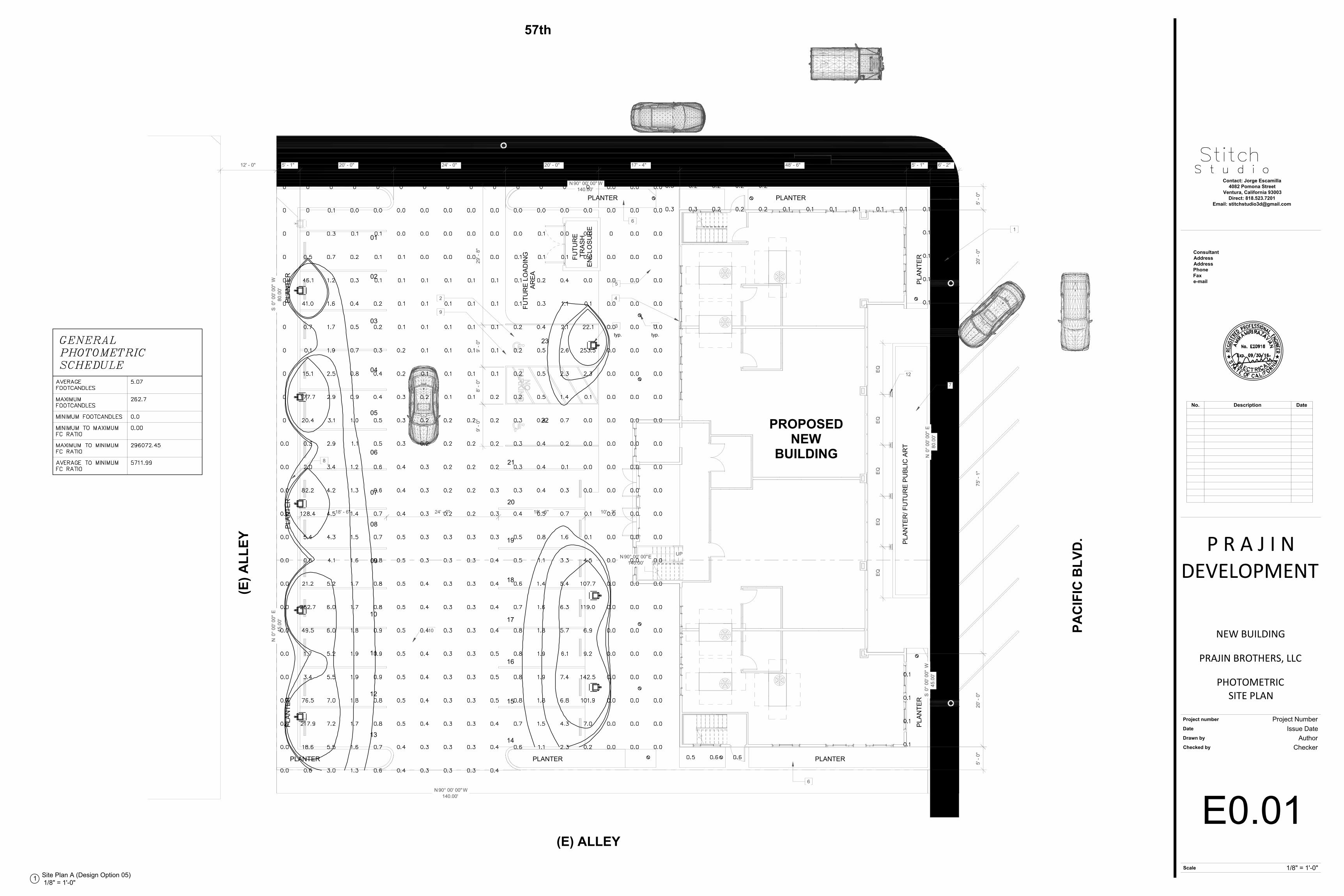
PHOTOMETRICSITE PLAN
Project Number
NEW BUILDING
P R A J I NDEVELOPMENT
Issue DateAuthor
Checker
PRAJIN BROTHERS, LLC
1/8" = 1'-0"1 Site Plan A (Design Option 05)
No. Description Date