5410 high speed counter input module - plcsystems.ru · the 5410 module can be wired and configured...
TRANSCRIPT
5410 High Speed Counter Input
Module Installation, Operation and Maintenance
Setup Manual
2/24/2017
5410 High Speed Counter Input Module
Document (Version 2.27.1.197) 2/24/2017 2 2
Copyright © 2014 - 2017 Schneider Electric Canada Inc.
All rights reserved.
The information provided in this documentation contains general descriptions and/or technical characteristics of the performance of the products contained herein. This documentation is not intended as a substitute for and is not to be used for determining suitability or reliability of these products for specific user applications. It is the duty of any such user or integrator to perform the appropriate and complete risk analysis, evaluation and testing of the products with respect to the relevant specific application or use thereof. Neither Schneider Electric nor any of its affiliates or subsidiaries shall be responsible or liable for misuse of the information contained herein. If you have any suggestions for improvements or amendments or have found errors in this publication, please notify us.
No part of this document may be reproduced in any form or by any means, electronic or mechanical, including photocopying, without express written permission of Schneider Electric.
All pertinent state, regional, and local safety regulations must be observed when installing and using this product. For reasons of safety and to help ensure compliance with documented system data, only the manufacturer should perform repairs to components.
Trademarks
Schneider Electric, ClearSCADA, SCADAPack, Solarpack, Realflo, Telepace, Telebus, SCADAServer, and Modbus are trademarks and the property of Schneider Electric SE, its subsidiaries and affiliated companies. All other trademarks are the property of their respective owners.
Microsoft and Windows are registered trademarks or trademarks of Microsoft Corporation in the United States and/or other countries.
Address
Schneider Electric Telemetry & Remote SCADA Solutions 415 Legget Drive, Suite 101, Kanata, Ontario K2K 3R1 Canada Direct Worldwide: +1 (613) 591-1943 Fax: +1 (613) 591-1022 Toll Free within North America: 1 (888) 267-2232 www.schneider-electric.com
5410 High Speed Counter Input Module
Document (Version 2.27.1.197) 2/24/2017 3 3
Table of Contents
Technical Support..........................................................................5
Technical Support: Americas, Europe, Middle East, Asia ..................................... 5 Technical Support: Australia .................................................................................. 5
Safety Information .........................................................................6
Important Information ............................................................................................. 6 Please Note ............................................................................................................ 7 Before You Begin ................................................................................................... 7 Operation and Adjustments ................................................................................... 7 Acceptable Use ...................................................................................................... 8
About The Book .............................................................................9
At a Glance ............................................................................................................ 9
Overview ....................................................................................... 10
Installation .................................................................................... 11
Field Wiring .......................................................................................................... 11 Address Selection ................................................................................................ 13 Operating Modes Selection .................................................................................. 14 De-Bounce Filter Selection .................................................................................. 15
Operation and Maintenance ........................................................ 16
Use with High Frequency Inputs .......................................................................... 16 Use with Mechanical Inputs ................................................................................. 16 Use with Optical Incremental Encoders ............................................................... 16 LED Indicators ...................................................................................................... 17 Maintenance ......................................................................................................... 17 Troubleshooting ................................................................................................... 17
Specifications .............................................................................. 19
Approvals and Certifications ...................................................... 21
5410 High Speed Counter Input Module
Document (Version 2.27.1.197) 2/24/2017 4 4
Index of Figures
Figure 1: 5410 Counter Input Module ................................................................ 10
Figure 2: Field Wiring Examples ........................................................................ 11
Figure 3: Optical Encoder Wiring Example ........................................................ 12
Figure 4: Model 5410 Module Address Switches ............................................... 14
Figure 5: Configuration Switches ....................................................................... 15

5410 High Speed Counter Input Module
Document (Version 2.27.1.197) 2/24/2017 5 5
Technical Support
Questions and requests related to any part of this documentation can be directed to one of the following support centers:
Technical Support: Americas, Europe, Middle East, Asia
Available Monday to Friday 8:00am – 6:30pm Eastern Time
Toll free within North America 1-888-226-6876
Direct Worldwide +1-613-591-1943
Email [email protected]
Technical Support: Australia
Inside Australia 1300 369 233
Email [email protected]
5410 High Speed Counter Input Module
Document (Version 2.27.1.197) 2/24/2017 6 6
Safety Information
Important Information
Read these instructions carefully and look at the equipment to become familiar with the device before trying to install, operate, service, or maintain it. The following special messages may appear throughout this documentation or on the equipment to warn of potential hazards or to call attention to information that clarifies or simplifies a procedure.
The addition of this symbol to a Danger or Warning safety message indicates that an electrical hazard exists, which will result in personal injury if the instructions are not followed.
This is the safety alert symbol. It is used to alert you to potential personal injury hazards. Obey all safety messages that follow this symbol to avoid possible injury or death.
DANGER DANGER indicates a hazardous situation which, if not avoided, will result in death or serious injury.
WARNING WARNING indicates a hazardous situation which, if not avoided, can result in death or serious injury.
CAUTION CAUTION indicates a potentially hazardous situation which, if not avoided, can result in minor or moderate injury.
NOTICE NOTICE is used to address practices not related to physical injury.
5410 High Speed Counter Input Module
Document (Version 2.27.1.197) 2/24/2017 7 7
Please Note
Electrical equipment should be installed, operated, serviced, and maintained only by qualified personnel. No responsibility is assumed by Schneider Electric for any consequences arising out of the use of this material.
A qualified person is one who has skills and knowledge related to the construction and operation of electrical equipment and the installation, and has received safety training to recognize and avoid the hazards involved.
Before You Begin
Do not use this product on machinery lacking effective point-of-operation guarding. Lack of effective point-of-operation guarding on a machine can result in serious injury to the operator of that machine.
WARNING
EQUIPMENT OPERATION HAZARD
Verify that all installation and set up procedures have been completed.
Before operational tests are performed, remove all blocks or other temporary holding means used for shipment from all component devices.
Remove tools, meters, and debris from equipment.
Failure to follow these instructions can result in death or serious injury.
Follow all start-up tests recommended in the equipment documentation. Store all equipment documentation for future reference.
Test all software in both simulated and real environments.
Verify that the completed system is free from all short circuits and grounds, except those grounds installed according to local regulations (according to the National Electrical Code in the U.S.A, for instance). If high-potential voltage testing is necessary, follow recommendations in equipment documentation to prevent accidental equipment damage.
Operation and Adjustments
The following precautions are from the NEMA Standards Publication ICS 7.1-1995 (English version prevails):
Regardless of the care exercised in the design and manufacture of equipment or in the selection and ratings of components, there are hazards that can be encountered if such equipment is improperly operated.
It is sometimes possible to misadjust the equipment and thus produce unsatisfactory or unsafe operation. Always use the manufacturer’s instructions as a guide for functional adjustments. Personnel who have access to these adjustments should be familiar with the equipment
5410 High Speed Counter Input Module
Document (Version 2.27.1.197) 2/24/2017 8 8
manufacturer’s instructions and the machinery used with the electrical equipment.
Only those operational adjustments actually required by the operator should be accessible to the operator. Access to other controls should be restricted to prevent unauthorized changes in operating characteristics.
Acceptable Use
SCADAPack controllers and expansion modules are intended for use in monitoring and controlling non-critical equipment only. They are not intended for safety-critical applications.
WARNING
UNACCEPTABLE USE
Do not use SCADAPack controllers and expansion modules as an integral part of a safety system. These devices are not safety products.
Failure to follow these instructions can result in death or serious injury.
CAUTION
EQUIPMENT OPERATION HAZARD
When devices are used for applications with technical safety requirements, the relevant instructions must be followed.
Use only Schneider Electric software or approved software with Schneider Electric hardware products.
Failure to follow these instructions can result in minor or moderate injury.
5410 High Speed Counter Input Module
Document (Version 2.27.1.197) 2/24/2017 9 9
About The Book
At a Glance
Document Scope
This manual describes operation and maintenance of the 5410 High Speed Counter Input module.
Validity Notes
This document is valid for all versions of the 5410 High Speed Counter Input module.
Product Related Information
WARNING UNINTENDED EQUIPMENT OPERATION
The application of this product requires expertise in the design and programming of control systems. Only persons with such expertise should be allowed to program, install, alter and apply this product.
Follow all local and national safety codes and standards.
Failure to follow these instructions can result in death or serious injury.
User Comments
We welcome your comments about this document. You can reach us by e-mail at [email protected].
5410 High Speed Counter Input Module
Document (Version 2.27.1.197) 2/24/2017 10 10
Overview
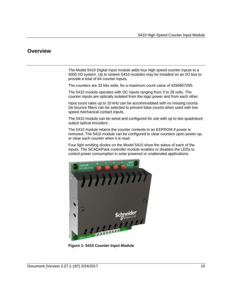
The Model 5410 Digital Input module adds four high speed counter inputs to a 5000 I/O system. Up to sixteen 5410 modules may be installed on an I/O bus to provide a total of 64 counter inputs.
The counters are 32 bits wide, for a maximum count value of 4294967295.
The 5410 module operates with DC inputs ranging from 3 to 28 volts. The counter inputs are optically isolated from the logic power and from each other.
Input count rates up to 10 kHz can be accommodated with no missing counts. De-bounce filters can be selected to prevent false counts when used with low speed mechanical contact inputs.
The 5410 module can be wired and configured for use with up to two quadrature output optical encoders.
The 5410 module retains the counter contents in an EEPROM if power is removed. The 5410 module can be configured to clear counters upon power-up, or clear each counter when it is read.
Four light emitting diodes on the Model 5410 show the status of each of the inputs. The SCADAPack controller module enables or disables the LEDs to control power consumption in solar powered or unattended applications.
Figure 1: 5410 Counter Input Module
5410 High Speed Counter Input Module
Document (Version 2.27.1.197) 2/24/2017 11 11
Installation
The installation of the 5410 module requires mounting the module on the 7.5mm by 35mm DIN rail and connecting the module to the system I/O Bus. Refer to the System Configuration Guide for complete information on system layout, I/O Bus cable routing and module installation.
Field Wiring
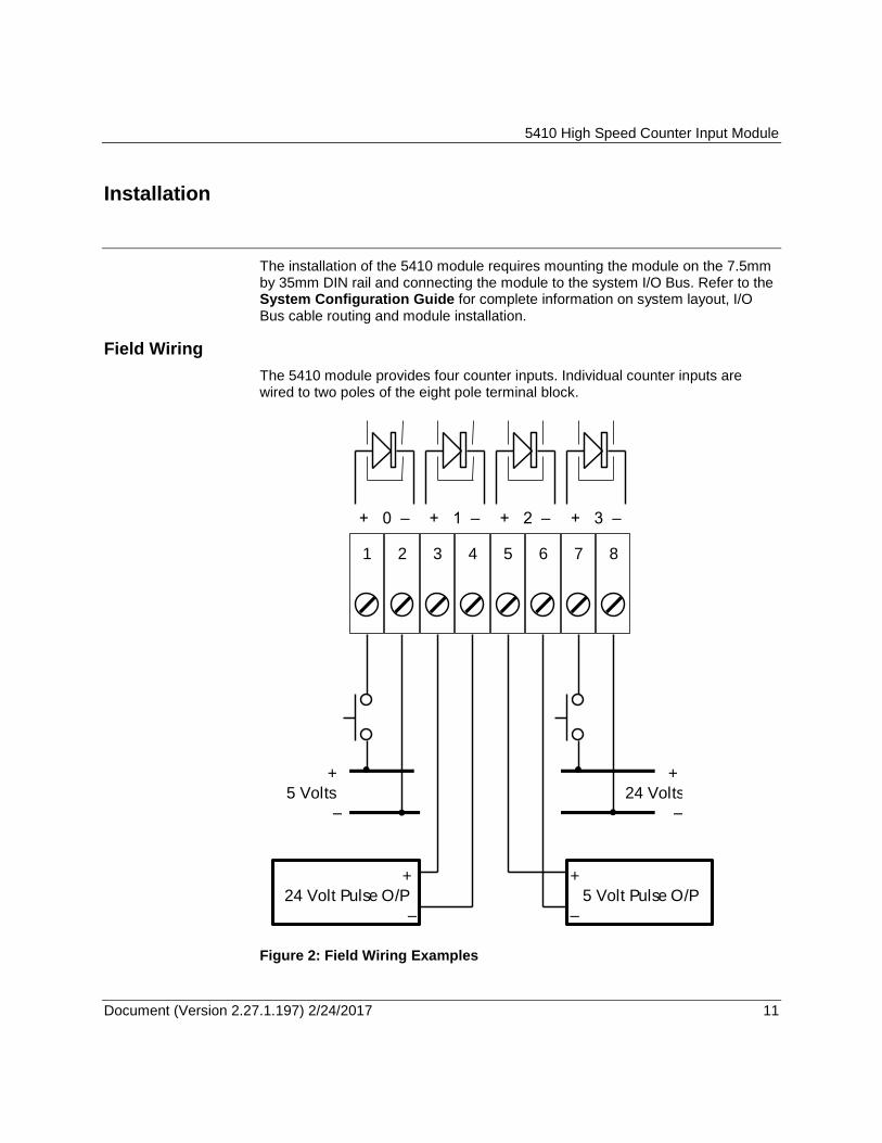
The 5410 module provides four counter inputs. Individual counter inputs are wired to two poles of the eight pole terminal block.
1 2 3 4 5 6 7 8
+ 1 – + 2 – + 3 –+ 0 –
+
24 Volts
–
+
5 Volts
–
+
24 Volt Pulse O/P
–
+
5 Volt Pulse O/P
–
Figure 2: Field Wiring Examples
5410 High Speed Counter Input Module
Document (Version 2.27.1.197) 2/24/2017 12 12
1 2 3 4 5 6 7 8
+ 1 – + 2 – + 3 –+ 0 –
+
5 Volts
–
Bourns Rotary
Optical Encoder
B + A NC GND
0 321
CCW CW CCW CW
1st Encoder 2nd Encoder
Note: Second Optical
Encoder not shown.
LED Direction Indicators
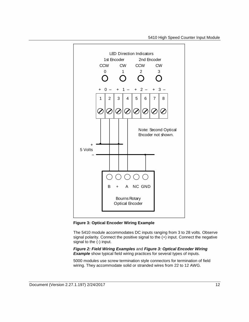
Figure 3: Optical Encoder Wiring Example
The 5410 module accommodates DC inputs ranging from 3 to 28 volts. Observe signal polarity. Connect the positive signal to the (+) input. Connect the negative signal to the (-) input.
Figure 2: Field Wiring Examples and Figure 3: Optical Encoder Wiring Example show typical field wiring practices for several types of inputs.
5000 modules use screw termination style connectors for termination of field wiring. They accommodate solid or stranded wires from 22 to 12 AWG.
5410 High Speed Counter Input Module
Document (Version 2.27.1.197) 2/24/2017 13 13
The connector is removable. This allows module replacement without disturbing the field wiring. Leave enough slack in the wiring for the connector to be removed.
Remove power before servicing unit.
To remove the connector:
Pull the connector upward from the board. Apply even pressure to both ends of the connector.
To install the connector:
Line up the pins on the module with the holes in the connector.
Push the connector onto the pins. Apply even pressure to both ends on the connector.
Address Selection
The 5000 I/O bus will support a maximum of twenty I/O (input/output) modules. 5000 I/O module types may be combined in any manner to the maximum supported by the controller used. The types of input and output modules available are:
Digital Input modules
Digital Output modules
Analog Input modules
Analog Output modules
Counter Input modules
Each type of I/O module, connected to the I/O bus, has a unique I/O module address. Different types of I/O modules may have the same module address.
The address range supported by the SCADAPack controller module may restrict the I/O module address range. Refer to the controller manual for the maximum address supported.
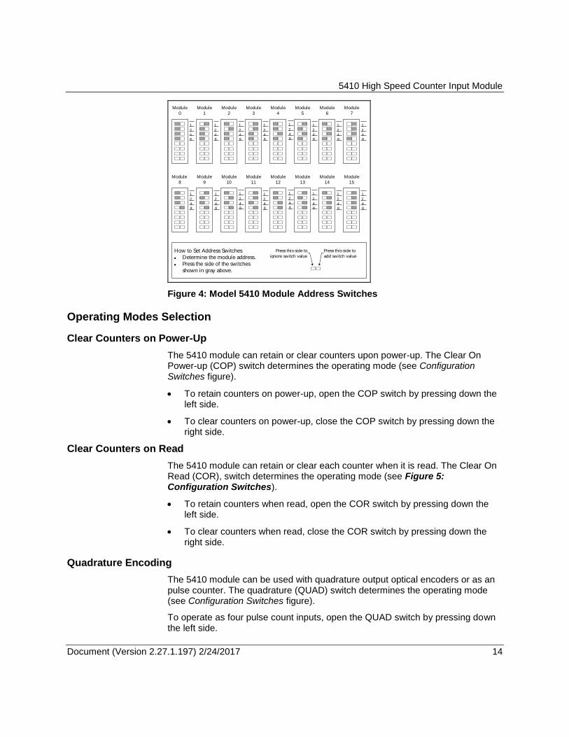
The four address switches labeled 1, 2, 4, and 8 set the module address. To set the address:
Open the four switches by pressing down the left side of Address SW1.
Close the switches that total the desired address.
Figure 4: Model 5410 Module Address Switches shows the switch settings for each of the 16 module addresses.
5410 High Speed Counter Input Module
Document (Version 2.27.1.197) 2/24/2017 14 14
Press this side to
add switch value
Press this side to
ignore switch value
Module
0
How to Set Address Switches
Determine the module address.
Press the side of the switches
shown in gray above.
Module
1
Module
2
Module
3
Module
4
Module
5
Module
6
Module
7
Module
8
Module
9
Module
10
Module
11
1
4
2
8
1
4
2
8
1
4
2
8
1
4
2
8
1
4
2
8
1
4
2
8
1
4
2
8
1
4
2
8
1
4
2
8
1
4
2
8
1
4
2
8
1
4
2
8
Module
12
Module
13
Module
14
Module
15
1
4
2
8
1
4
2
8
1
4
2
8
1
4
2
8
Figure 4: Model 5410 Module Address Switches
Operating Modes Selection
Clear Counters on Power-Up
The 5410 module can retain or clear counters upon power-up. The Clear On Power-up (COP) switch determines the operating mode (see Configuration Switches figure).
To retain counters on power-up, open the COP switch by pressing down the left side.
To clear counters on power-up, close the COP switch by pressing down the right side.
Clear Counters on Read
The 5410 module can retain or clear each counter when it is read. The Clear On Read (COR), switch determines the operating mode (see Figure 5: Configuration Switches).
To retain counters when read, open the COR switch by pressing down the left side.
To clear counters when read, close the COR switch by pressing down the right side.
Quadrature Encoding
The 5410 module can be used with quadrature output optical encoders or as an pulse counter. The quadrature (QUAD) switch determines the operating mode (see Configuration Switches figure).
To operate as four pulse count inputs, open the QUAD switch by pressing down the left side.
5410 High Speed Counter Input Module
Document (Version 2.27.1.197) 2/24/2017 15 15
To operate as two quadrature output optical encoder inputs, close the QUAD switch by pressing down the right side.
De-Bounce Filter Selection
Mechanical contact inputs often exhibit switch bounce, which can cause multiple counts to be accumulated on each opening and closing of the switch contact. To keep switch bounce from causing false counts, de-bounce filters (one for each input) should be engaged.
To eliminate false counts, enable de-bounce filtering by pressing the right side of the switch.
To count high frequency signals, disable de-bounce filtering by pressing the left side of the switch.
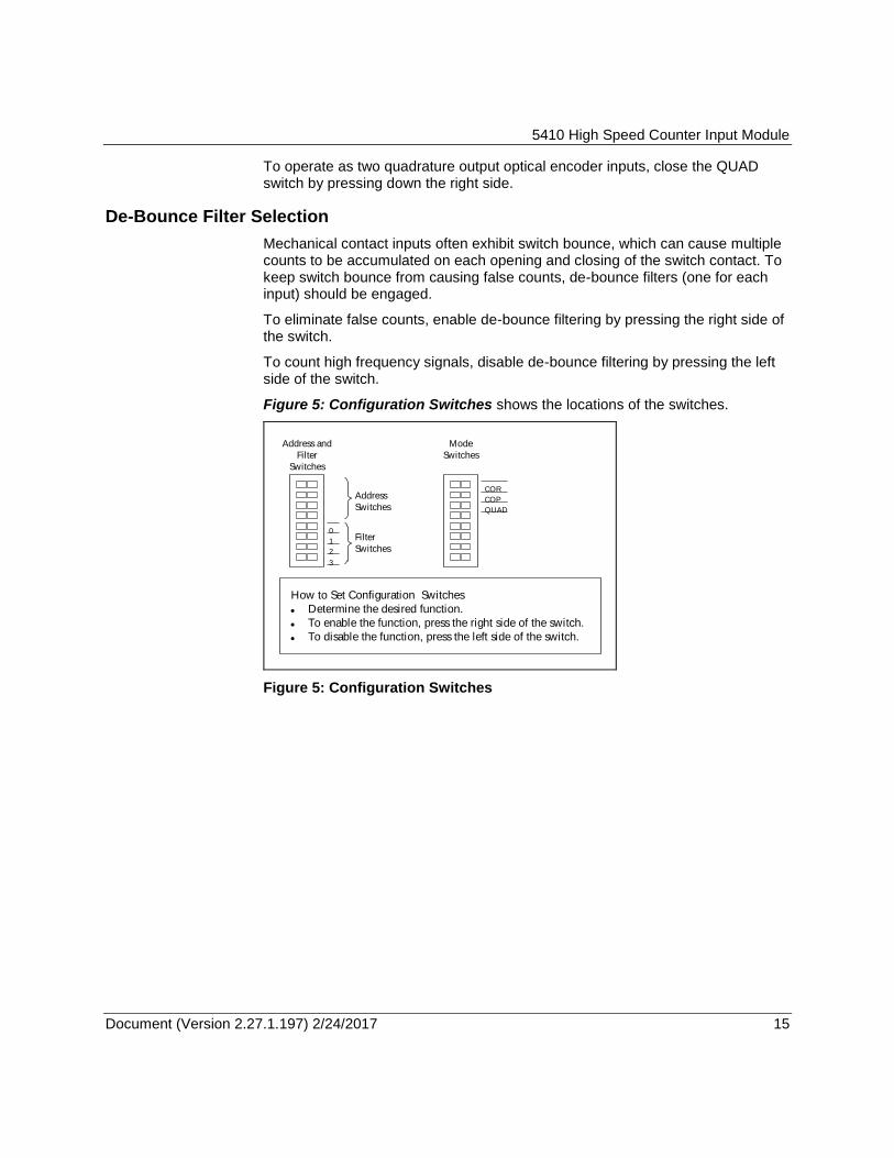
Figure 5: Configuration Switches shows the locations of the switches.
0
2
1
Mode
Switches
Address and
Filter
Switches
How to Set Configuration Switches
Determine the desired function.
To enable the function, press the right side of the switch.
To disable the function, press the left side of the switch.
COR
QUAD
COP
3
Filter
Switches
Address
Switches
Figure 5: Configuration Switches
5410 High Speed Counter Input Module
Document (Version 2.27.1.197) 2/24/2017 16 16
Operation and Maintenance
The model 5410 counter module accumulates pulse inputs at frequencies up to 10 kHz. Input pulse on and off times must be at least fifty microseconds in duration to be detected.
The counters accumulate input pulses until the maximum count value of 4294967295 is reached. At the next input pulse, the counters will overflow and start counting again from zero.
When power is removed or the 5000 I/O System is reset, the 5410 counter module retains the accumulated count values in an EEPROM. A minimum of 100,000 (typically 1,000,000) power removals and reset cycles can be accepted by the EEPROM.
If the COP (Clear On Power-up) switch is open, the EEPROM is read and the count values are restored when power is restored or reset is removed. If the COP switch is closed, the counters will be cleared when power is restored or reset is removed.
To automatically clear each counter when it is read by the controller, the COR (Clear On Read) switch should be closed. Unread accumulated counts will be saved in the EEPROM during power removal and will be restored upon power up if the COP switch is open.
Use with High Frequency Inputs
When used with high frequency inputs, de-bounce filters are disabled. The maximum count frequency is 10 kHz. The minimum pulse low and pulse high width is 50 microseconds.
Use with Mechanical Inputs
Mechanical contact inputs often exhibit switch bounce. The high frequency ringing caused by switch bounce can cause multiple counts to be accumulated on each opening and closing of the switch contact.
To keep switch bounce from causing false counts, de-bounce filters (one for each input) should be enabled. To enable de-bounce filters, close the appropriate filter switch.
When de-bounce filtering is enabled, the maximum count frequency is 60 Hz. The minimum pulse low and pulse high width is 8.3 milliseconds.
Use with Optical Incremental Encoders
The 5410 module can be used with quadrature output optical incremental encoders. Close the QUAD switch to select quadrature phase detection mode. When the QUAD switch is closed, the four inputs are dedicated for use with two
5410 High Speed Counter Input Module
Document (Version 2.27.1.197) 2/24/2017 17 17
optical encoders. If only one encoder is installed the remaining two inputs cannot be used as regular counters.
Refer to Figure 3: Optical Encoder Wiring Example for an example of wiring to a Bourns Rotary Optical Encoder. This particular optical encoder has a 2-bit gray code. Channel A leads channel B by 90º (electrical) with clockwise rotation. The encoder is wired such that an electrical low output from the encoder will turn on the counter inputs. This results in channel B leading channel A.
When wired as shown, counter 0 will increment for clockwise rotation and decrement for counter-clockwise rotation. LED 1 is on for clockwise rotation and LED 0 is on for counter-clockwise rotation.
A second optical encoder uses inputs 2 and 3. When wired in the same manner as shown, counter 1 will increment for clockwise rotation and decrement for counter-clockwise rotation. LED 2 is on for clockwise rotation and LED 3 is on for counter-clockwise rotation.
LED Indicators
The 5410 digital input module has one red status LED per counter input. This LED is on when the input voltage exceeds three volts DC. If the de-bounce filter is on, the input frequency needs to be 60 hertz or lower for the LED to illuminate.
For ease of viewing, the LEDs use pulse stretching to allow pulses as brief as fifty microseconds to be observed.
The SCADAPack controller module, through the I/O bus, powers the LEDs. The LEDs can be disabled to conserve power. Refer to the controller manual for more information.
Maintenance
This module requires no routine maintenance or calibration. If the module is not functioning correctly, contact Schneider Electric Technical Support for more information and instructions for returning the module for repair.
Troubleshooting
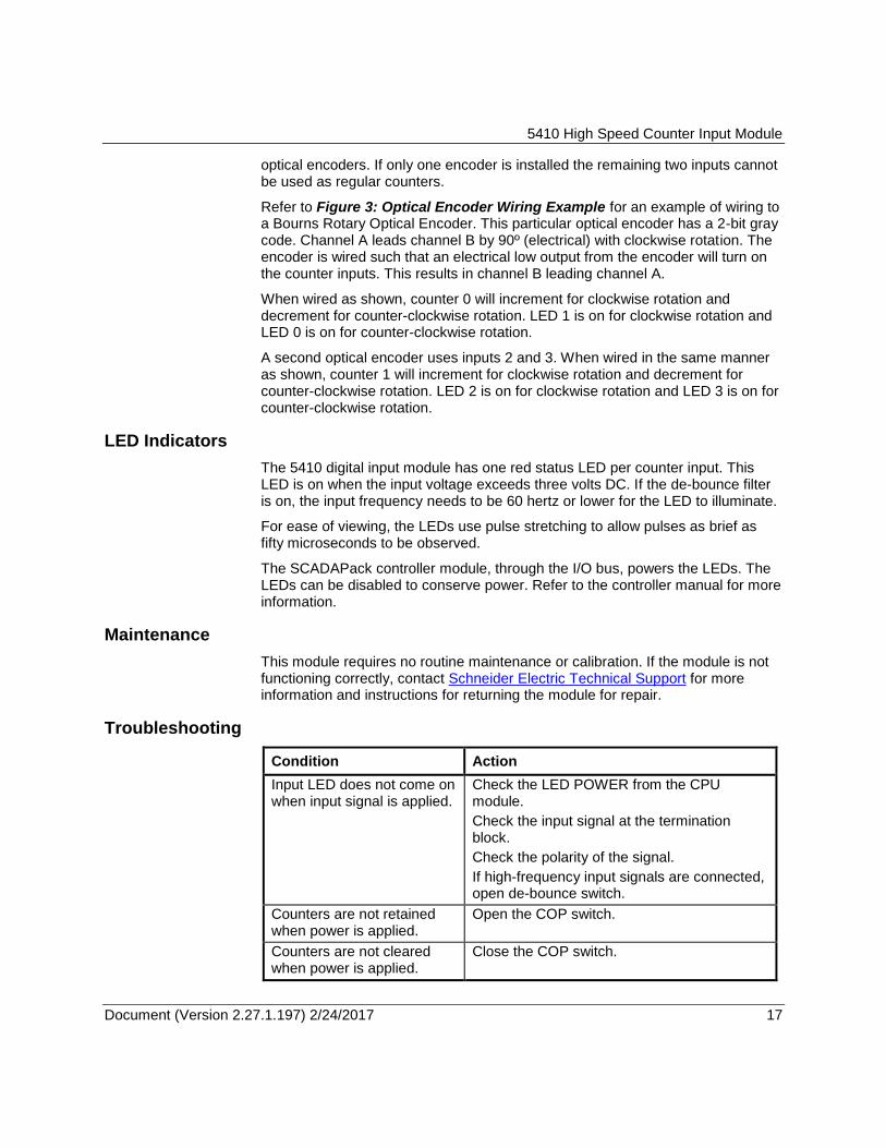
Condition Action
Input LED does not come on when input signal is applied.
Check the LED POWER from the CPU module.
Check the input signal at the termination block.
Check the polarity of the signal.
If high-frequency input signals are connected, open de-bounce switch.
Counters are not retained when power is applied.
Open the COP switch.
Counters are not cleared when power is applied.
Close the COP switch.
5410 High Speed Counter Input Module
Document (Version 2.27.1.197) 2/24/2017 18 18
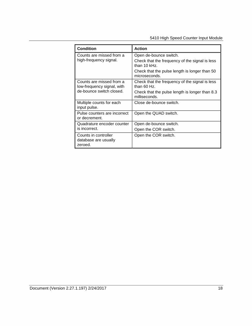
Condition Action
Counts are missed from a high-frequency signal.
Open de-bounce switch.
Check that the frequency of the signal is less than 10 kHz.
Check that the pulse length is longer than 50 microseconds.
Counts are missed from a low-frequency signal, with de-bounce switch closed.
Check that the frequency of the signal is less than 60 Hz.
Check that the pulse length is longer than 8.3 milliseconds.
Multiple counts for each input pulse.
Close de-bounce switch.
Pulse counters are incorrect or decrement.
Open the QUAD switch.
Quadrature encoder counter is incorrect.
Open de-bounce switch.
Open the COR switch.
Counts in controller database are usually zeroed.
Open the COR switch.
5410 High Speed Counter Input Module
Document (Version 2.27.1.197) 2/24/2017 19 19
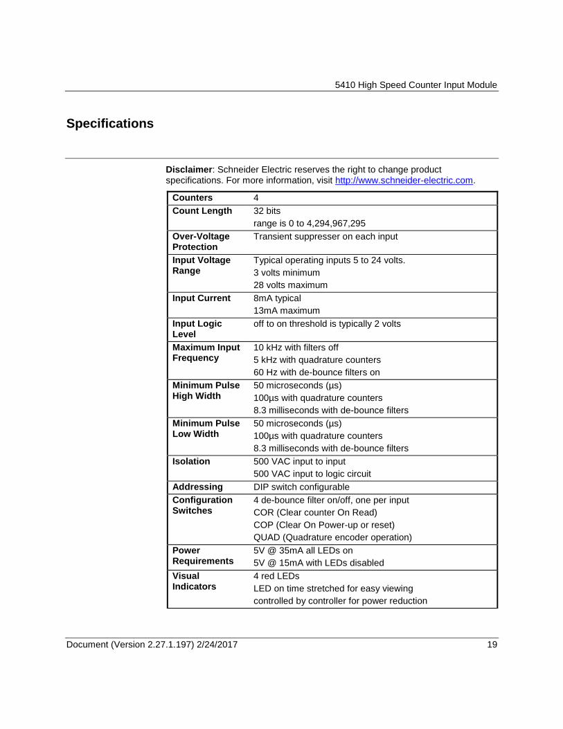
Specifications
Disclaimer: Schneider Electric reserves the right to change product specifications. For more information, visit http://www.schneider-electric.com.
Counters 4
Count Length 32 bits
range is 0 to 4,294,967,295
Over-Voltage Protection
Transient suppresser on each input
Input Voltage Range
Typical operating inputs 5 to 24 volts.
3 volts minimum
28 volts maximum
Input Current 8mA typical
13mA maximum
Input Logic Level
off to on threshold is typically 2 volts
Maximum Input Frequency
10 kHz with filters off
5 kHz with quadrature counters
60 Hz with de-bounce filters on
Minimum Pulse High Width
50 microseconds (µs)
100µs with quadrature counters
8.3 milliseconds with de-bounce filters
Minimum Pulse Low Width
50 microseconds (µs)
100µs with quadrature counters
8.3 milliseconds with de-bounce filters
Isolation 500 VAC input to input
500 VAC input to logic circuit
Addressing DIP switch configurable
Configuration Switches
4 de-bounce filter on/off, one per input
COR (Clear counter On Read)
COP (Clear On Power-up or reset)
QUAD (Quadrature encoder operation)
Power Requirements
5V @ 35mA all LEDs on
5V @ 15mA with LEDs disabled
Visual Indicators
4 red LEDs
LED on time stretched for easy viewing
controlled by controller for power reduction
5410 High Speed Counter Input Module
Document (Version 2.27.1.197) 2/24/2017 20 20
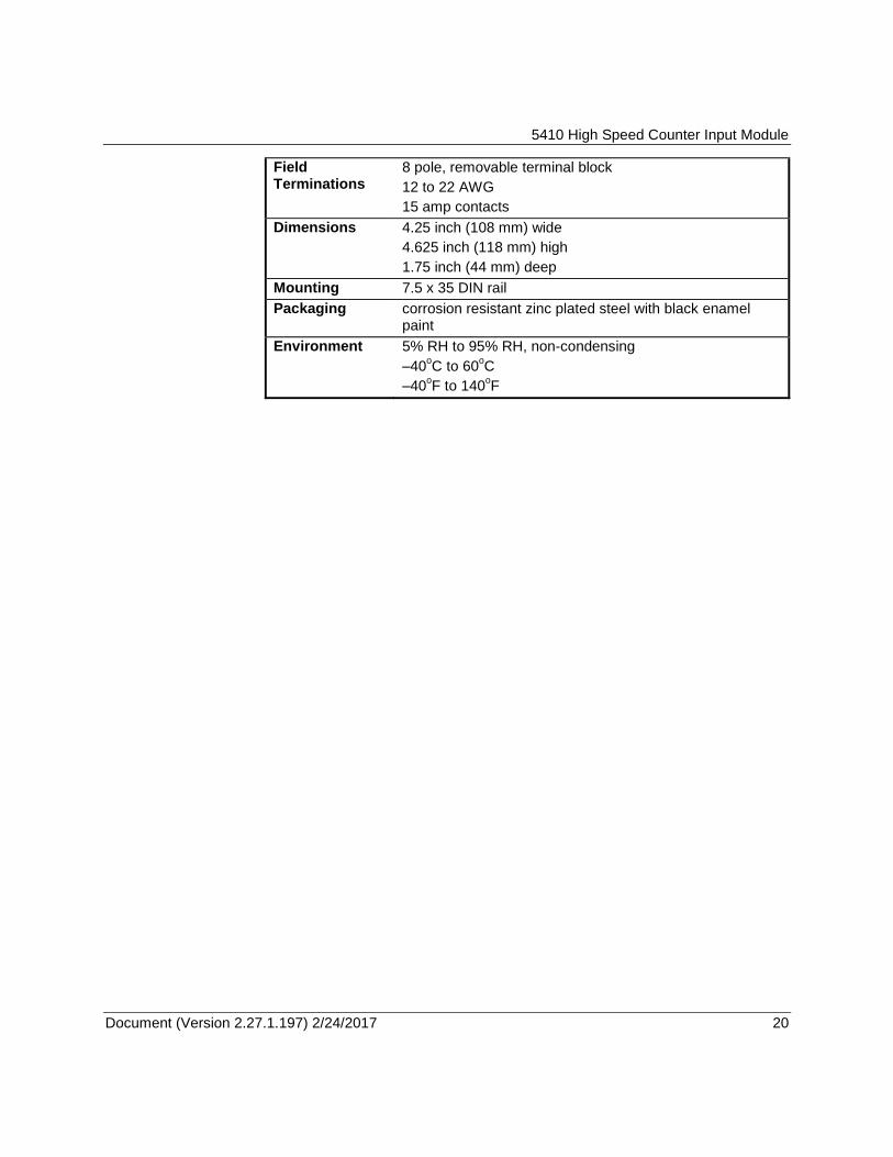
Field Terminations
8 pole, removable terminal block
12 to 22 AWG
15 amp contacts
Dimensions 4.25 inch (108 mm) wide
4.625 inch (118 mm) high
1.75 inch (44 mm) deep
Mounting 7.5 x 35 DIN rail
Packaging corrosion resistant zinc plated steel with black enamel paint
Environment 5% RH to 95% RH, non-condensing
–40oC to 60
oC
–40oF to 140
oF
5410 High Speed Counter Input Module
Document (Version 2.27.1.197) 2/24/2017 21 21
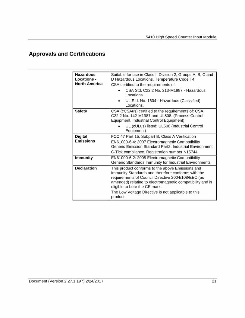
Approvals and Certifications
Hazardous Locations - North America
Suitable for use in Class I, Division 2, Groups A, B, C and D Hazardous Locations. Temperature Code T4
CSA certified to the requirements of:
CSA Std. C22.2 No. 213-M1987 - Hazardous Locations.
UL Std. No. 1604 - Hazardous (Classified) Locations.
Safety CSA (cCSAus) certified to the requirements of: CSA C22.2 No. 142-M1987 and UL508. (Process Control Equipment, Industrial Control Equipment)
UL (cULus) listed: UL508 (Industrial Control Equipment)
Digital Emissions
FCC 47 Part 15, Subpart B, Class A Verification
EN61000-6-4: 2007 Electromagnetic Compatibility Generic Emission Standard Part2: Industrial Environment
C-Tick compliance. Registration number N15744.
Immunity EN61000-6-2: 2005 Electromagnetic Compatibility Generic Standards Immunity for Industrial Environments
Declaration This product conforms to the above Emissions and Immunity Standards and therefore conforms with the requirements of Council Directive 2004/108/EEC (as amended) relating to electromagnetic compatibility and is eligible to bear the CE mark.
The Low Voltage Directive is not applicable to this product.