5056.426od tc42 outdoor...
TRANSCRIPT
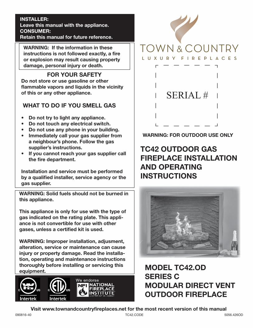
TC42 OUTDOOR GAS FIREPLACE INSTALLATION AND OPERATING INSTRUCTIONS
090816-40 TC42.CODE 5056.426OD
MODEL TC42.ODSERIES CMODULAR DIRECT VENTOUTDOOR FIREPLACE
WARNING: If the information in these instructions is not followed exactly, a fi re or explosion may result causing property damage, personal injury or death.
WARNING: Solid fuels should not be burned in this appliance.
This appliance is only for use with the type of gas indicated on the rating plate. This appli-ance is not convertible for use with other gases, unless a certifi ed kit is used.
WARNING: Improper installation, adjusment, alteration, service or maintenance can cause injury or property damage. Read the installa-tion, operating and maintenance instructions thoroughly before installing or servicing this equipment.
FOR YOUR SAFETYDo not store or use gasoline or other fl ammable vapors and liquids in the vicinity of this or any other appliance.
WHAT TO DO IF YOU SMELL GAS
• Do not try to light any appliance.• Do not touch any electrical switch. • Do not use any phone in your building.• Immediately call your gas supplier from
a neighbour’s phone. Follow the gas supplier’s instructions.
• If you cannot reach your gas supplier call the fi re department.
Installation and service must be performed by a qualifi ed installer, service agency or the gas supplier.
INSTALLER: Leave this manual with the appliance.CONSUMER: Retain this manual for future reference.
SERIAL #
WARNING: FOR OUTDOOR USE ONLY
Visit www.townandcountryfi replaces.net for the most recent version of this manual
Table of Contents
Caution ............................................................................ 3 Safety .............................................................................. 3 Important Note for the Commonwealth of Massachusetts .................................. 4 This Fireplace Is Intended For Outdoor Use Only! .......... 5 Fireplace Dimensions ...................................................... 6 Minimum Clearances To Combustible Material ............... 6 Installation Requirements ................................................ 7 Window Frame Removal ................................................. 7 Top Standoffs .................................................................. 8 Locating The Fireplace .................................................... 8 Framing and Finishing ..................................................... 9 TC42 Steel Stud Framing Kit ......................................... 11
Assembly Instructions ............................................. 11 Adjustable Lintel ............................................................ 13 Hearth Extension ........................................................... 14 Honeywell Control Valve Plumbing and Electrical ......... 15
Installation ............................................................... 15 Gas Supply .................................................................... 16 Gas Pressure Check ...................................................... 16
Correct gas pressure requirement: ......................... 16 Propane Conversion ...................................................... 17 Venting ........................................................................... 18 Wall Termination Venting ............................................... 18
Wall opening: ........................................................... 18Wall thimble: ............................................................ 19Vent System Components ...................................... 19Vent pipe: ................................................................ 20Wall vent terminal: ................................................... 20
Wall Termination Venting Chart ..................................... 21 Roof Termination Venting Chart ..................................... 22
Ceiling Opening: ...................................................... 23Ceiling Firestop: ...................................................... 23Vent Pipe: ................................................................ 23Roof Support Bracket: ............................................ 23Roof Vent Terminal: ................................................. 24
Vent Terminal Clearance ................................................ 25Roof Pitch Table ...................................................... 25
Vent Terminal Minimum Clearances .............................. 25 Vent Pipe Sealant .......................................................... 26 Vent Restrictor Adjustment ........................................... 27 Firebox Panels Installation ............................................ 28 Lighting Instructions ...................................................... 30 First Fire ......................................................................... 30 Maintenance .................................................................. 31
Glass Panel: ............................................................ 31Annual Inspection: .................................................. 31Periodically: ............................................................. 31
Replacement Parts ........................................................ 32 Replacement Parts – Honeywell Control System .......... 33 Wiring Diagram .............................................................. 34 Wall Shield Ceiling Firestop Thimble .............................. 35 Wall Termination Kit ....................................................... 35 Roof Termination Kit ....................................................... 35 Vent Pipe Dimensions ................................................... 36 Vent Offset Chart ........................................................... 37 Rating Label Location ................................................... 38
2TC42.CODE_090816-405056.426OD

FOR YOUR SAFETY - Do not install or operate your Town & Country fireplace without first reading and under-standing this manual. Any installation or operational deviation from the following instructions voids the Town & Country FireplacesTM Warranty and may prove hazardous.
This appliance and its individual shut off valve must be disconnected from gas supply piping system during any pressure testing of that system at test pressures in excess of 1/2 psig (3.5 kPa).
This appliance must be isolated from the gas supply piping system by closing its individual manual shut off valve during any pressure testing of the gas supply piping system at test pressures equal to or less than 1/2 psig (3.5 kPa).
Note: When lit for the first time, the appliance will emit a slight odour for a couple of hours. This is due to the curing of paints, sealants and lubricants used in the manufacturing process. This condition is temporary. Open doors and win-dows to ventilate area. Smoke and fumes caused by the curing process may cause discomfort to some individuals.
Do not use the fireplace if any part has been under water. Immediately call a qualified service technician to inspect the fireplace and to replace any part of the control system and any gas control which has been under water.
Due to high temperatures, this gas appliance should be located out of traffic and away from furniture and draperies.
Children and adults should be alerted to the hazards of high surface temperatures and should stay away to avoid burns or clothing ignition.
Young children should be carefully supervised when they are in the same room as the appliance.
Clothing or other flammable material should not be placed on or near the appliance.
Any grill, panel or door removed for servicing the unit must be replaced prior to operating. Failure to do so may create a hazardous condition.
Installation and repair should be done by a qualified service person. The appliance should be inspected before use and at least annually by a professional service person. More frequent cleaning may be required due to excessive lint from carpeting, bedding material, etc.. It is imperative that control compartments, burners and circulating air passageways of the appliance be kept clean.
It is our policy that no responsibility is assumed by the Company or by any of its employees or representatives for any damages caused by an inoperable, inadequate, or unsafe condition which is the result, either directly or indirectly, of any improper operation or installation procedures.
This appliance must not be connected to a chimney flue serving a separate solid fuel burning appliance.
3TC42.CODE_090816-40 5056.426OD
Caution
Safety
We recommend that our gas hearth products be installed and serviced by professionals who are certified in the United States by the National Fireplace Institute® (NFI) as NFI Gas Specialists
DANGER: If you smell gas:
1. Shut off gas to the appliance.
2. Extinguish any open flame.
3. If odor continues, keep away from the appliance and imme-diately call your gas supplier or fire department.
WARNING: Do not store or use gasoline or other flammable vapors and liquids in the vicinity of this or any other appliance.
DANGER: CARBON MONOXIDE HAZARD
This appliance can produce carbon monoxide which has no odor.Using it in an enclosed space can kill you. Never use this appliance in an enclosed space such as a camper, tent, car or home.

Important Note for the Commonwealth of Massachusetts
From Massachusetts Rules and Regulations 248 CMR 5.08:
(a) For all side wall horizontally vented gas fuelled equipment installed in every dwelling, building or structure used in whole or in part for residential
purposes, including those owned or operated by the Commonwealth and where the side wall exhaust vent termination is less than seven (7) feet
above finished grade in the area of the venting, including but not limited to decks and porches, the following requirements shall be satisfied.
1. INSTALLATION OF CARBON MONOXIDE DETECTORS. At the time of installation of the side wall horizontal vented gas fuelled equipment, the
installing plumber or gas fitter shall observe that a hard wired carbon monoxide detector with an alarm and battery back-up is installed on the floor
level where the gas equipment is to be installed, in addition, the installing plumber or gas fitter shall observe that a battery operated or hard-wired
carbon monoxide detector with an alarm is installed on each additional level of the dwelling, building or structure served by the side wall horizontal
vented gas fuelled equipment. It shall be the responsibility of the property owner to secure the services of qualified licensed professionals for the
installation of hard-wired carbon monoxide detectors.
a. In the event that the side wall horizontally vented gas fuelled equipment is installed in a crawl space or an attic, the hard-wired carbon monoxide
detector with alarm and battery back-up may be installed on the next adjacent floor level.
b. In the event that the requirements of this subdivision cannot be met at the time of completion of installation, the owner shall have a period of thirty
(30) days to comply with the above requirements; provided, however, that during said thirty (30) day period, a battery operated carbon monoxide
detector with an alarm shall be installed.
2. APPROVED CARBON MONOXIDE DETECTORS. Each carbon monoxide detector as required in accordance with the above provisions shall
comply with NFPA 720 and be ANSI/UL 2034 listed as IAS certified.
3. SIGNAGE. A metal or plastic identification plate shall be permanently mounted to the exterior of the building at a minimum height of eight (8) feet
above grade directly in line with the exhaust vent terminal for the horizontally vented gas fuelled heating appliance or equipment. The sign shall
read, in print size no less than one-half (1/2) inch in size, “GAS VENT DIRECTLY BELOW. KEEP CLEAR OF ALL OBSTRUCTIONS”.
4. INSPECTION. The state or local gas inspector of the side wall horizontally vented gas fuelled equipment shall not approve the installation unless,
upon inspection, the inspector observes carbon monoxide detectors and signage installed in accordance with the provisions of 248 CMR 5.089(2)
(a) 1 through 4.
(b) EXEMPTIONS. The following equipment is exempt from 248 CMR 5.089(2)(a) 1 through 4.
1. The equipment listed in Chapter 10 entitled “Equipment Not Required To Be Vented” in the most current edition of NFPA 54 as adopted by the
Board; and
2. Product Approved side wall horizontal vented gas fuelled equipment installed in a room or structure separate from the dwelling, building or structure
used in whole or in part for residential purposes.
(c) MANUFACTURER REQUIREMENTS – GAS EQUIPMENT VENTING SYSTEM PROVIDED. When the manufacturer of Product Approved side wall
horizontally vented gas equipment provides a venting system design or venting system components with the equipment, the instructions provided
by the manufacturer for installation of the equipment and the venting system shall include:
1. Detailed instructions for the installation of the venting system design or the venting system components; and
2. A complete parts list for the venting system design or venting system.
(d) MANUFACTURER REQUIREMENTS – GAS EQUIPMENT VENTING SYSTEM NOT PROVIDED. When the manufacturer of a Product Approved
side wall horizontally vented gas fuelled equipment does not provide the parts for venting the fuel gases, but identifies “special venting systems”, the
following requirements shall be satisfied by the manufacturer.
1. The referenced “special venting system” instructions shall be included with the appliance or equipment installation instructions; and
2. The “special venting systems” shall be Product Approved by the Board, and the instructions for that system shall include a parts list and detailed
installation instructions.
(e) A copy of all installation instructions for all Product Approved side wall horizontally vented gas fuelled equipment, all venting instructions, all parts
lists for venting instructions, and/or all venting design instructions shall remain with the appliance or equipment at the completion of the installation.
4TC42.CODE_090816-405056.426OD

• The fireplace must be located inside of a weatherproof enclosure.
• Flashing must be installed around the fireplace opening in accordance with local building codes in order to prevent moisture from entering the enclosure.
• A drip pan (not supplied with the unit) must be installed under the fireplace and be provided with a means of draining.
• Care must be taken to select materials and building practices which will protect the enclo-sure and fireplace from exposure to moisture.
This Fireplace Is Intended For Outdoor Use Only!
5TC42.CODE_090816-40 5056.426OD
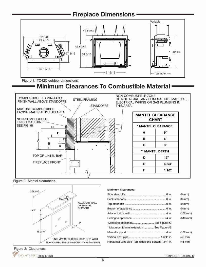
52 3/829 7/16
43 13/16
27 3/16
53 15/16
38 3/16
11 11/16
43 13/16
Variable
42 1/4
Variable
Figure 1: TC42C outdoor dimensions.
* MANTEL CLEARANCE
A 9”
B 6”
C 3”
** MANTEL DEPTH
D 12”
E 6 3/4”
F 1 1/2”
MANTEL CLEARANCECHART
MAY USE COMBUSTIBLE FACING MATERIAL IN THIS AREA
NON-COMBUSTIBLE FINISH MATERIAL SEE FIG #8
NON-COMBUSTIBLE ZONE. DO NOT INSTALL ANY COMBUSTIBLE MATERIAL,-ELECTRICAL WIRING OR GAS PLUMBING IN THIS AREA.
COMBUSTIBLE FRAMING AND FINISH WALL ABOVE STANDOFFS
STANDOFFS
STEEL FRAMING
FIREPLACE FRONT
TOP OF LINTEL BAR
AB
C
D
E
F
Figure 2: Mantel clearances.
**
*
Minimum Clearances:
Side standoffs .......................................................0 in. (0 mm)
Back standoffs ......................................................0 in. (0 mm)
Top standoffs ........................................................ 0 in. (0 mm)
Bottom of appliance ..............................................0 in. (0 mm)
Adjacent side wall .................................................4 in. (102 mm)
Ceiling to appliance ............................................ 24 in. (610 mm)
*Mantel to appliance .............................See Figure #2
**Maximum Mantel extension ..............See Figure #2
Mantel support ...................................................... 4 in. (102 mm)
Vertical vent pipe ..........................................1 3/4" in. (45 mm)
Horizontal Vent pipe (Top, sides and bottom) 1 3/4" in. (45 mm)
24”
38 3/16”
4”
MANTEL
ADJACENT WALLOR MANTEL SUPPORT
CEILING
UNIT MAY BE RECESSED UP TO 6” WITH NON-COMBUSTIBLE MASONRY TYPE MATERIAL
Figure 3: Clearances.
6TC42.CODE_090816-405056.426OD
Fireplace Dimensions
Minimum Clearances To Combustible Material
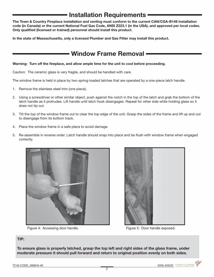
Figure 4: Accessing door handle. Figure 5: Door handle exposed.
The Town & Country Fireplace installation and venting must conform to the current CAN/CGA-B149 installation code (in Canada) or the current National Fuel Gas Code, ANSI Z223.1 (in the USA), and approved per local codes. Only qualified (licensed or trained) personnel should install this product.
In the state of Massachusetts, only a licensed Plumber and Gas Fitter may install this product.
Warning: Turn off the fireplace, and allow ample time for the unit to cool before proceeding.
Caution: The ceramic glass is very fragile, and should be handled with care.
The window frame is held in place by two spring-loaded latches that are operated by a one-piece latch handle.
1. Remove the stainless steel trim (one piece).
2. Using a screwdriver or other similar object, push against the notch in the top of the latch and grab the bottom of the latch handle as it protrudes. Lift handle until latch hook disengages. Repeat for other side while holding glass so it does not tip out.
3. Tilt the top of the window frame out to clear the top edge of the unit. Grasp the sides of the frame and lift up and out to disengage from its bottom track.
4. Place the window frame in a safe place to avoid damage.
5. Re-assemble in reverse order. Latch handle should snap into place and be flush with window frame when engaged correctly.
TIP:
To ensure glass is properly latched, grasp the top left and right sides of the glass frame, under moderate pressure it should pull forward and return to original position evenly on both sides.
7TC42.CODE_090816-40 5056.426OD
Installation Requirements
Window Frame Removal
EXAMPLES OF COMMON LOCATIONSSEE FIG 1 FOR DIMENSIONS
Figure 7: Common locations.
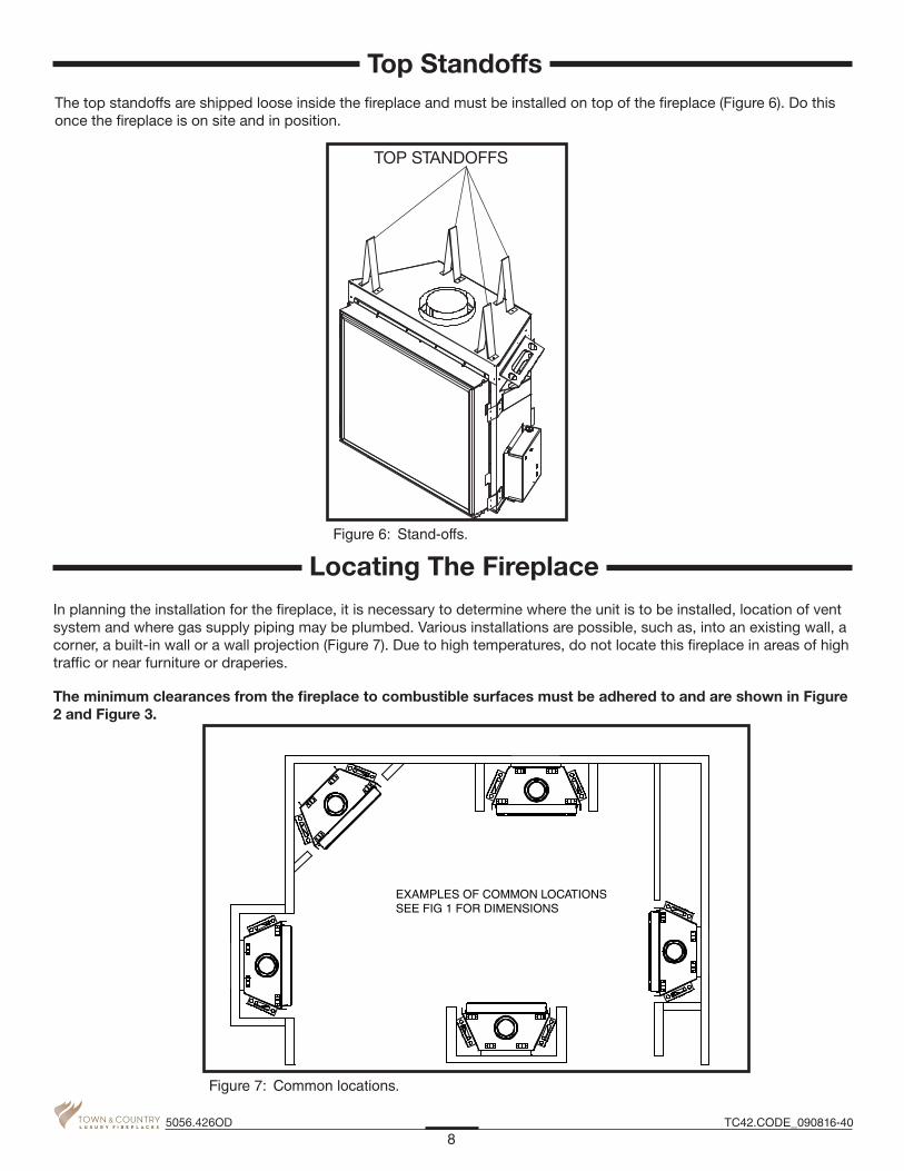
The top standoffs are shipped loose inside the fireplace and must be installed on top of the fireplace (Figure 6). Do this once the fireplace is on site and in position.
In planning the installation for the fireplace, it is necessary to determine where the unit is to be installed, location of vent system and where gas supply piping may be plumbed. Various installations are possible, such as, into an existing wall, a corner, a built-in wall or a wall projection (Figure 7). Due to high temperatures, do not locate this fireplace in areas of high traffic or near furniture or draperies.
The minimum clearances from the fireplace to combustible surfaces must be adhered to and are shown in Figure 2 and Figure 3.
TOP STANDOFFS
Figure 6: Stand-offs.
8TC42.CODE_090816-405056.426OD
Locating The Fireplace
Top Standoffs

Note: The fireplace should be in place and venting installed before framing in or building an enclosure around the unit.
The Town & Country fireplace must be framed in as described below or totally enclosed with non-combustible material, such as facing brick.
Determine the total thickness of fac-ing material to be used. A thickness of 3/4" will allow the finishing surface to be flush with the front of the unit. If preferred, additional masonry type non-combustible material can be installed above and to the sides up to 6 inches proud of the appliance. The finishing material must not inter-fere with glass frame access.
A Steel Stud Framing Kit is supplied with the fireplace and must be used unless the fireplace is totally enclosed with non-combustible material. Assemble the framing kit as per the
instructions on page 11 & page 12 of this manual. Attach the steel frame to the fireplace once the fire-place is in its final position. Secure the steel frame to the framing brackets on each side of the unit. Ensure that the studs are set back far enough to allow for thickness of finishing surface.
The sides, back and top of the fire-place can be framed in up to the steel studs and the fireplace standoffs using conventional lumber. Consult local building codes for specific requirements.
Due to high temperatures, non-combustible backer board, such as cement board, calcium silicate board (Figure 10) or its equivalent, must be used to sheet in the front of the fire-place, extending 12" above and 5 1/2" to the side of the framing edge bars (Figure 9). Standard sheet rock (dry wall) may be used beyond this. Taped and mudded joints may crack dueto the elevated temperatures.
Fabricate and install appropriate flash-ing to local building code.
Note: Installing unit without flashing installed will void the warranty
Note: Provide proper drainage to divert water underneath the unit
Chase Insulation: When installing this fireplace against a non-insulated exte-rior wall or chase, it is recommended that the outer walls be insulated to same degree as other exterior walls. Do not place fireplace directly against the insulation. Cover the insulation and plastic vapour barrier with a solid surface, such as dry wall (sheet rock). Consult local codes. Do not insulate or use plastic vapour barrier within the framing kit.
CAUTION: See Figure 10 before proceeding
IT IS HIGHLY RECOMENDEDTHAT A FULL HEADER BE INSTALLED ABOVE THE METAL FRAMING KIT
ALL OTHER FRAMING CAN BE DONE WITH CONVENTIONALLUMBER
NON-COMBUSTIBLE ZONE. DO NOT INSTALL ANY COMBUSTIBLE MATERIAL, ELECTRICAL WIRING, INSULATION, PLASTIC VAPOR BARRIER OR GAS PLUMBING WITHIN THE STEEL STUD FRAMING
STEEL STUD FRAMING KIT DIMENSIONS(Supplied with fireplace)
56 1/4”
53 3/4”
Figure 8: Framing kit dimensions.
9TC42.CODE_090816-40 5056.426OD
Framing and Finishing

12”
5 1/2”
Non-combustible board detail
NON-COMBUSTIBLE BOARD
Non-combustible materials must extend 12” above and 5 1/2” to the sides of the framing edges.
Figure 9: Non-combustible board allowances.CALCIUM SILICATEBOARD
If finishing the wall above the unit with paint, the framing kit shipped with the unit should be discarded and full length metal studs should be used instead to finish and frame around the unit.
It is recommended to use full sheets of calcium silicate board or its equivalent.
Follow the manufacturers mount-ing and finishing instructions
Figure 10: Calcium silicate board.MAXIMUM FACING DEPTH
STEEL STUDS
NON-COMBUSTIBLE MATERIAL
NON-COMBUSTIBLE BOARD
Non-combustible recessed installation detail
Figure 11: Non-combustible recessed installation.
54"
56 1/4”
62"21 1/4”
30"
3/4"
56 1/4”
62"26 1/8"
56 1/4”
12 5/8”
3/4"
Including Sheetrock
Minimum combustible framing dimensions
87 11/16”
Note: Fireplace should be in its final location before framing.
Figure 12: Minimum combustible framing dimensions.
10TC42.CODE_090816-405056.426OD

1. Top Frame Assembly Lay out side studs (2) and center studs (4) on a large flat surface. Using the screws provided (1), attach the header stud (5) and the plate stud (6) to the center studs (4).
Assembly Instructions
Framing kit contents: Item Part # Description Qty.
1 5049.9912 SCREW, TEKS Pkg #8 x 1/2” 40
2 9093.03 STUD, SIDES, 53 3/4”L 2
3 9093.1 STUD, OUTER SIDES, 53 3/4”L 2
4 9935.000 STUD, CENTER, 14 15/16”L 2
5 9094 STUD, HEADER, 56 1/8”L 1 6 9934.000 STUD, PLATE, 47 15/16”L 1
7 9945.000 BASE PLATE , 6 1/2”L 2
1
2
3
4
5
6
7
Figure 13: Framing kit contents.
2
4
5
6
Figure 14: Top frame assembly.
11TC42.CODE_090816-40 5056.426OD
TC42 Steel Stud Framing Kit

3
7
5
Figure 15: Side stud placement.
Framingbrackets
5
7Access holes tomounting screws
Figure 16: Assembled frame.
Figure 17: Installing non-combustible board over frame.
2. Attach Side Studs (Legs) Attach the outer side studs (3) to the top of the header stud (5) (Figure 15). Fasten the outer side studs (3) at the bottom using the base plates (7).
3. Attach the Assembled Frame to the Unit Align the assembled frame to the fireplace framing brackets (Figure 16). Attach at the fastening points through the access holes in the outer side studs (3).
4. Secure to Existing Framing Secure the metal frame assem-bly to existing framing through the stud header (5) and the stud plates (7).
5. Install Non-combustible Board on top and sides
12TC42.CODE_090816-405056.426OD

Adjustable Lintel
Hemmededge
Flangededge
Figure 18: Adjustable lintel.
Decorative trim
Figure 19: Decorative trim.
Securingbolt
Figure 20: Lintel securing bolt.
1. The adjustable lintel assembly has two orientations for desired finish-ing. A flanged edge and a hemmed edge. The lintel comes factory installed with the flange edge out (Figure 18). If the desired edge is different from the factory setting, use the following steps to change it.
2. Remove the decorative window trim by lifting and pulling it to disengage from the window frame (Figure 19).
3. Loosen the securing bolts in the upper and lower corners on each side of the lintel and remove the lin-tel. Rotate the assembly to have the desired edge away from the fireplace (Figure 20).
4. The lintel assembly has a maxi-mum range of adjustability of 1” to accommodate varying facing material thicknesses. The maximum depth is 6” (Figure 22).
5. The lintel assembly can then be adjusted to align flush with your facing material by sliding in or out approximately 1”.
6. Tighten the securing bolts (Figure 20).
7. Re-attach the decorative window trim.
13TC42.CODE_090816-40 5056.426OD

1/4"
1"MAX
WINDOWFRAME
HEARTHEXTENSION
WINDOWTRACK
SUB-FLOOR
Figure 21: Hearth details.
Caution: While a hearth extension is not required and combustible flooring materials may be brought directly up to the fireplace, many materials (such as wood flooring) may not tolerate the radiant heat from this fireplace, resulting in discoloration, shrinking and cracking. For this reason, we suggest a non-combustible hearth that is no more than 1” above the bottom of the fireplace. If thicker, fireplaced must be raised accordingly.
Caution: Hearth extensions thicker than 1” will interfere with the window frame.
This fireplace may be recessed up to a maximum depth of 6”. This recess must be constructed from non combustible material. The space between the outside lintels and the firebox must be completely free of any debris and the window with trim fitted must be able to move freely. No building material is permit-ted to protrude past the lintel bars attached to the fireplace under ANY circumstance.
SIDE FACING CLEARANCES
ROCK FACEAREA
MINIMUM
6”
43 7/8” 37 3/4”
MINIMUM
Figure 22: Non-combustible recess allowances.
14TC42.CODE_090816-405056.426OD
Hearth Extension

Access panel
Figure 23: Access panel location.
The gas control system is located on the right hand side of the firebox behind an access panel and the decorative firebox panel (if installed). The fireplace is operated via a wall switch.
The wall control is connected to the fireplace by a 14-2 AWG wire, not supplied with the fireplace.
Installation
1. Place the fireplace in the desired location.
2. Remove the window from the fireplace.
3. Remove access panel from right hand side of the firebox (Figure 23).
4. Remove the cover from the electrical box (Figure 24).
5. Run one 110 V. AC switched electrical supply to the control box and connect to the transformer installed inside the control box (Figure 25). The fireplace oper-ates on 24V AC supplied by a transformer rated at 110 volts, 60Hz. See wiring diagram on page 34 for correct connections to the transformer.
6. Connect the gas supply to the gas inlet (Figure 26).
Electrical box cover
Figure 24: Electrical box cover.
Transformer, electrical connections
Figure 25: TC42 outdoor control with transformer.
GasInlet
Figure 26: Gas inlet on gas valve.
15TC42.CODE_090816-40 5056.426OD
Honeywell Control Valve Plumbing and Electrical

SUPPLY PRESSURE
MANIFOLDPRESSURE
Figure 27: Gas pressure test points.
Caution: The gas line should be installed by a qualified service person in accordance with all building codes. This sec-tion is intended as a guide for qualified technicians installing this appliance. Consult local and / or national building codes before proceeding.
• Gas supply line access holes are located at the top and left sides of the Control Box. Gas valve inlet accepts a 1/2" N.P.T. fitting. Correct gas line diameter must be used to assure proper operation and pressure.
• The fireplace has an input rate of 61,000 BTU/HR on both Natural Gas and Propane.
• NOTE: A sediment trap, as per national fuel gas code, must be installed in the gas supply line no more than 6 feet from the gas control valve to minimize the possibility of any loose scale or dirt within the gas supply line from entering the control valve.
• DO NOT HARD PIPE GAS LINE TO VALVE. A method of disconnecting the valve from the gas line such as a union or flare fitting must be provided to allow for repair or replacement of the gas valve.
• It is essential that a union or flanged connection be installed just upstream of the valve and inside the control com-partment to allow for repair or replacement of the gas valve.
Check local codes for additional requirements.
1. Connect the gas supply to the gas valve (Figure 26).
2. Turn on the gas supply and check that all connections are tight and leak free.
Correct gas pressure requirement:
Natural Gas Propane
Min. Pressure 5.0" WC 12.5" WC(For purpose of input adjustment)
Max. Pressure 13.9" WC 13.9" WC
Manifold PressureMaximum 3.8" WC 11" WCMinimum 2.1" WC 5.5" WC
Note: To test the gas pressure, turn off the gas supply before removing the plug from the supply pressure test port or manifold pressure test port.
Verify gas pressures with the fireplace lit and on the highest setting.
Please refer to the Burner Installation Manual for gas pressure testing procedure.
WARNING: The access panel including gasket must be reinstalled after conversion / installation or servicing has been completed. Failure to do so will cause overheating and premature failure of the control system.
16TC42.CODE_090816-405056.426OD
Gas Supply
Gas Pressure Check

Propane Conversion
Compression �tting
Ori�ceHousing
Figure 31: Completed pilot assembly.
Note: This fireplace comes with a pre installed Honeywell pilot. When installing the burner assembly, remove the pilot that came attached to the burner and discard.
DO NOT USE ANY OTHER PILOT WITH YOUR OUTDOOR UNIT OTHER THAN THE HONEYWELL PILOT THAT CAME INSTALLED IN THE FIREPLACE.
1. Using the valve conversion kit that came in the instruction pack, convert the valve to propane following the instruc-tions provided with the kit (Figure 28).
2. Remove the compression fitting from the bottom of the orifice housing and gently tap the pilot in your hand. The natural gas orifice should fall out (Figure 29).
3. Insert the propane orifice (Figure 30) that came in your instruction pack as shown into the orifice housing and reat-tach the pilot to the compression fitting and pilot tube.
Figure 28: Propane valve conversion kit.
Ori�ce
Ori�ceHousing
Compression �tting
Figure 29: Orifice inserted into housing.
Figure 30: Orifice for propane conversion.
17TC42.CODE_090816-40 5056.426OD

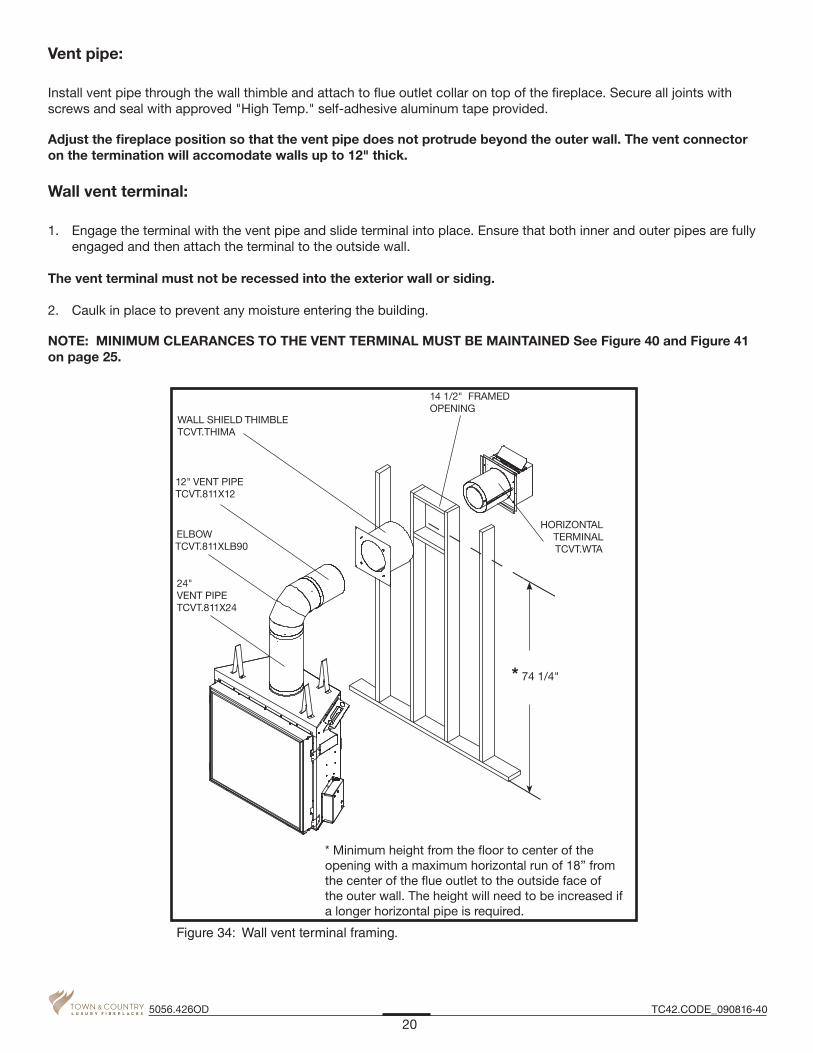
Wall opening:
Determine the exact position of the fireplace so that the vent pipe is centered (if possible) between two building framing members. Consult your local building codes prior to proceeding. The vent kit will accommodate up to a maximum wall thickness of 12 inches.
1. Having determined the position of the fireplace, cut and frame a 14 1/2 inch opening centred at a minimum height of 74 1/4 inches above the floor (Figure 34). The opening may be round or square. Height of the opening will vary with each installation. As the horizontal vent run increases, so does the minimum vertical rise. See Figure 35.
IMPORTANT: When locating the opening, it should be noted that vent terminal clearances must be maintained. See “Vent Terminal Minimum Clearances” on page 25 for proper clearances.
A minimum 2 foot length of pipe is required off the top of the fireplace for any wall termination. With this minimum verti-cal rise in combination with a 90° elbow, a maximum horizontal run of 18 inches is permitted (See Figure 35). For longer horizontal runs greater than 18 inches, increase vertical rise appropriately.
The rise and run must be constrained to the boundaries of the chart shown in Figure 35. The horizontal run of vent must have a 1/4" rise for every 1 ft. of run towards the termination.
Before installing venting for this unit, the installer should read these instructions to ensure that the proper vent configura-tion has been selected.
Use only Town and Country Termination kits: TCVT.WTA - Wall Termination Kit TCVT.RTA - Roof Termination Kit
Vent system components approved for use with the Town and Country Fireplace are shown in Fig. #33.
Various combinations of vertical and horizontal runs may be used. See Figure 35 and See Figure 36 for details. For optimum performance and flame appearance, keep the vent length to a minimum and limit the number of elbows. Connections between each vent system component must be tightly joined, secured with sheet metal screws and sealed with high temperature self adhesive tape. A horizontal run of vent should have a 1/4" rise for every 1 ft. of run towards the termination.
CAUTION: UNDER NO CONDITION SHOULD COMBUSTIBLE MATERIAL BE CLOSER THAN 1 3/4 INCHES FROM THE TOP AND 1 3/4 INCHES FROM THE SIDES OF A HORIZONTAL SECTION AND 1 3/4 INCHES FROM THE VERTICAL SECTIONS OF THE VENT PIPE.
18TC42.CODE_090816-405056.426OD
Venting
Wall Termination Venting

Wall thimble:
Where a vent pipe passes through a combustible wall, a wall thimble/shield must be used to retain insulation and main-tain proper clearances. The wall thimble may be cut to length for various wall thicknesses up to 12" thick.
Measure the wall thickness including the siding. Trim the shield to match the wall thickness. Position the wall thimble from inside through the 14-1/2" opening. Properly adjusted, the thimble should be flush with the outer wall surface.
Town & Country part # 12" Pipe Length ..................................................... TCVT.811X1218" Pipe Length ..................................................... TCVT.811X1824" Pipe Length ..................................................... TCVT.811X2448" Pipe Length ..................................................... TCVT.811X4812" Adjustable Pipe Length .............................TCVT.811X12ADJ45° Elbow ..........................................................TCVT.811XLB4590° Elbow ..........................................................TCVT.811XLB90Wall/Offset Support .............................................. TCVT.811XOS
Wall Termination Kit .................................................... TCVT.WTARoof Termination Kit .................................................... TCVT.RTAWall Shield/Ceiling Firestop .................................... TCVT.THIMA
Roof Flashing, Adjustable .................................TCVT.811FLADJRoof Flashing, Flat .............................................TCVT.811FLFLTRoof Flashing, Steep .........................................TCVT.811FLSTP or any flashing that fits 11" pipe
WALL THIMBLE AND VENT MUST NOT PROTRUDE BEYOND SIDING
Figure 32: Wall thimble and vent position limits.
TRIM TO LENGTH
Figure 33: Trimming thimble.
Vent System Components
19TC42.CODE_090816-40 5056.426OD
HORIZONTAL TERMINAL TCVT.WTA
14 1/2" FRAMED OPENING
WALL SHIELD THIMBLE TCVT.THIMA
ELBOW TCVT.811XLB90
24" VENT PIPE TCVT.811X24
12" VENT PIPE TCVT.811X12
* 74 1/4"
* Minimum height from the �oor to center of the opening with a maximum horizontal run of 18” from the center of the �ue outlet to the outside face of the outer wall. The height will need to be increased if a longer horizontal pipe is required.
Figure 34: Wall vent terminal framing.
Vent pipe:
Install vent pipe through the wall thimble and attach to flue outlet collar on top of the fireplace. Secure all joints with screws and seal with approved "High Temp." self-adhesive aluminum tape provided.
Adjust the fireplace position so that the vent pipe does not protrude beyond the outer wall. The vent connector on the termination will accomodate walls up to 12" thick.
Wall vent terminal:
1. Engage the terminal with the vent pipe and slide terminal into place. Ensure that both inner and outer pipes are fully engaged and then attach the terminal to the outside wall.
The vent terminal must not be recessed into the exterior wall or siding. 2. Caulk in place to prevent any moisture entering the building.
NOTE: MINIMUM CLEARANCES TO THE VENT TERMINAL MUST BE MAINTAINED See Figure 40 and Figure 41 on page 25.
20TC42.CODE_090816-405056.426OD

NOTE: The vent must not exceed a total length of 68 feet. Any combination of rise and run may be used but must be constrained to the boundaries of this chart. A total of 4 90° elbows or combination of other elbows equalling 90° can be used without reducing horizontal run. For each additional 90° elbow, or an equal combi-nation of elbows, reduce horizontal vent run by 2 feet. Ensure vent pipe is properly supported.
74 1/4”
** All dimensions are approximate. Both rise and run may vary with different combinations of pipe.
24" Pipelengthminimum
AMinimum rise
BPipe length
CMaximum run
DPipe length
Max.
74 1/4” 1-24” 18" 1-12"
78 1/2” 1-12” 1-18" 75 3/4" 1-48" 1-12"
84 1/2” 1-24" 1-12” 11' 2" 2-48" 1-24"
90 1/2” 1-24” 1-18" 15' 10 1/2"3-48" 1-24"
1-12"
98 1/4” 1-48” 20’ 10 1/2” 5-48"
For other rise/run combinations see chart below
**
Figure 35: TC42 outdoor run - rise chart.
21TC42.CODE_090816-40 5056.426OD
Wall Termination Venting Chart

NOTE: The vent must not exceed a total length of 68 feet. Any combination of rise and run may be used but must be con-strained to the boundaries of this chart. A total of 4 90° elbows or combination of other elbows equalling 90° can be used without reducing horizontal run. For each additional 90° elbow, or an equal combination of elbows, reduce horizontal vent run by 2 feet. Ensure vent pipe is properly supported.
** All dimensions are approximate. Both rise and run may vary with different combinations of pipe.
24" Pipe length minimum
AMinimum rise
BPipe length
CMaximum run
DPipe length Maximum
74 1/4” 1-24” 29" 1-12"
78 1/2” 1-12” 1-18" 77 1/4" 1-48" 1-12"
84 1/2” 1-24" 1-12” 11' 1 1/2" 2-48" 1-24"
90 1/2” 1-24" 1-18" 15' 10"3-48" 1-24"
1-12"
98 1/4” 1-48” 20’ 10” 5-48"
For other rise/run combinations see chart below
**
Figure 36: TC42 outdoor vertical rise - run chart.
Roof Termination Venting Chart
22TC42.CODE_090816-405056.426OD
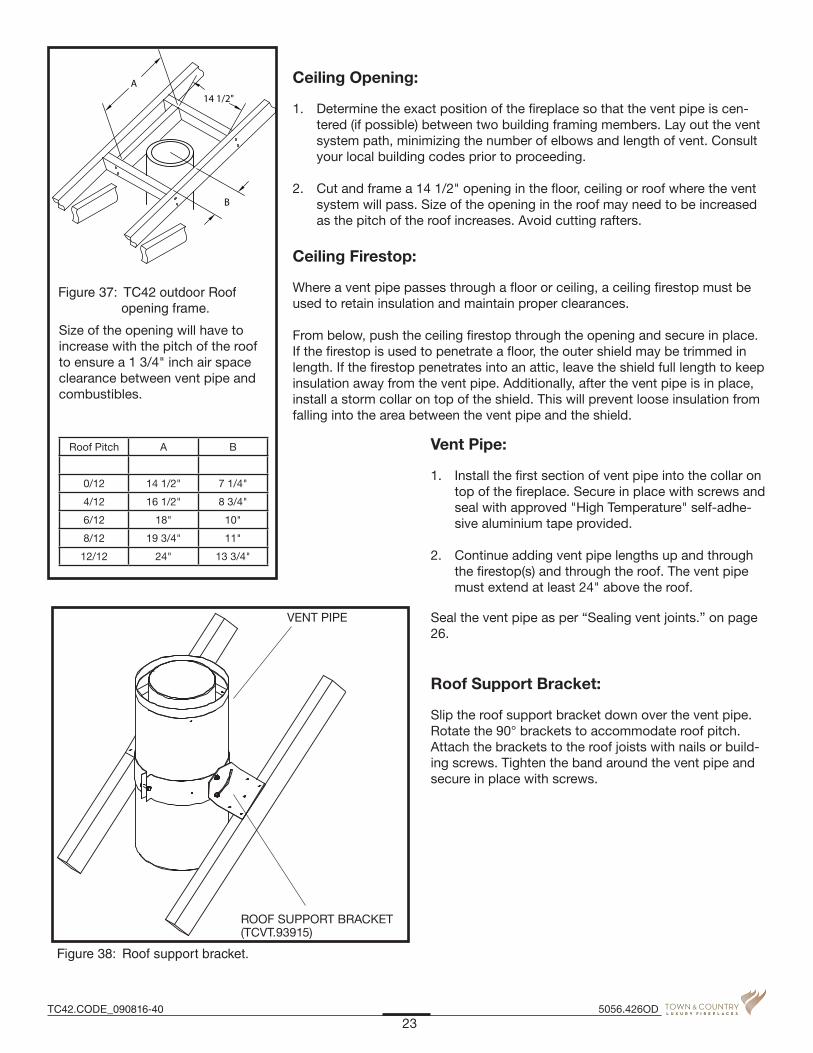
Ceiling Opening:
1. Determine the exact position of the fireplace so that the vent pipe is cen-tered (if possible) between two building framing members. Lay out the vent system path, minimizing the number of elbows and length of vent. Consult your local building codes prior to proceeding.
2. Cut and frame a 14 1/2" opening in the floor, ceiling or roof where the vent system will pass. Size of the opening in the roof may need to be increased as the pitch of the roof increases. Avoid cutting rafters.
Ceiling Firestop:
Where a vent pipe passes through a floor or ceiling, a ceiling firestop must be used to retain insulation and maintain proper clearances.
From below, push the ceiling firestop through the opening and secure in place. If the firestop is used to penetrate a floor, the outer shield may be trimmed in length. If the firestop penetrates into an attic, leave the shield full length to keep insulation away from the vent pipe. Additionally, after the vent pipe is in place, install a storm collar on top of the shield. This will prevent loose insulation from falling into the area between the vent pipe and the shield.
Vent Pipe:
1. Install the first section of vent pipe into the collar on top of the fireplace. Secure in place with screws and seal with approved "High Temperature" self-adhe-sive aluminium tape provided.
2. Continue adding vent pipe lengths up and through the firestop(s) and through the roof. The vent pipe must extend at least 24" above the roof.
Seal the vent pipe as per “Sealing vent joints.” on page 26.
Roof Support Bracket:
Slip the roof support bracket down over the vent pipe. Rotate the 90° brackets to accommodate roof pitch. Attach the brackets to the roof joists with nails or build-ing screws. Tighten the band around the vent pipe and secure in place with screws.
Size of the opening will have to increase with the pitch of the roof to ensure a 1 3/4" inch air space clearance between vent pipe and combustibles.
Roof Pitch A B
0/12 14 1/2" 7 1/4"
4/12 16 1/2" 8 3/4"
6/12 18" 10"
8/12 19 3/4" 11"
12/12 24" 13 3/4"
B
14 1/2"A
Figure 37: TC42 outdoor Roof opening frame.
VENT PIPE
ROOF SUPPORT BRACKET (TCVT.93915)
Figure 38: Roof support bracket.
23TC42.CODE_090816-40 5056.426OD

VERTICAL TERMINATION CAP(TCVT.9365)
FLASHING
STORM COLLAR(TC42.90665)
MASTIC
NOTE: Adjustable for various roof pitches from �at roof to 12 / 12 pitch roof.
VENT PIPE
Figure 39: Roof vent terminal.
Roof Vent Terminal:
1. Place the roof flashing over the vent pipe, secure and seal it to the roof using the methods and materials appropriate for the type of roof on the building. Shingle roof example shown in Figure 39.
2. Place the storm collar down over the vent pipe until it is level. Tighten storm collar for a snug fit. Apply a thick hori-zontal ring of mastic around the pipe at top of the storm collar.
3. Lower the roof vent terminal cap over the vent pipe and secure in place with screws provided. Seal screw heads and joint with caulking to prevent any moisture entering the venting system.
24TC42.CODE_090816-405056.426OD

A= *12 inches (30 cm) min. Clearances above grade, veranda, porch, deck, or balcony
B= *12 inches (30 cm) min. Clearance to window or door that may be opened
C= 12 inches (30 cm) min. Clearance to permanently closed window recommended to prevent condensation on window
D= 30 inches (76 cm) min. Vertical clearance to ventilated soffit located above the terminal within a horizontal distance of 2 feet (60 cm) from the edge of the terminal
E= 30 inches (76 cm) min. Clearance to unventilated soffit
F= 6 inches (15 cm) min. Clearance to outside corner
G= 6 inches (15 cm) min. Clearance to inside corner
H= 3 feet (90 cm) min. *Not to be installed above a meter/regulator assembly within 3 feet (90 cm) horizontally from the center-line of the regulator
I= *6 feet (1.8 m) min. Clearance to service regulator vent outlet
J= *12 inches (30 cm) min. Clearance to non mechanical air supply inlet to building or the combustion air inlet to any other appliance
K= *6 feet (1.8 m) min. Clearance to a mechanical air supply inlet
L= *7 feet (2.1 m) min. ^ Clearance above paved side-walk or a paved driveway located on public property
M= **30 inches (76 cm) min Clearance under veranda, porch, deck, or balcony
^ a vent shall not terminate directly above a side-walk or paved driveway which is located between two single family dwellings and serves both dwellings* ** only permitted if veranda, porch, deck, or balcony is fully open on a minimum of 2 sides beneath the floor* * as specified in CGA B149 Installation Codes, Note: local Codes or Regulation may require different clearances * for U.S.A. Installations follow the current National Fuel Gas Code, ANSI Z223.1
Minimum clearances to the vent terminal must be maintained as shown in Figure 40. Measure clearances to the nearest edge of termination hood.
NOTE: Vent terminal must not be recessed NOTE: LOCAL CODES OR REGULATIONS MAY REQUIRE DIFFERENT CLEARANCES.
ft m Flat to 6/12 1.00 0.30 Over 6/12 to 7/12 1.25 0.38 Over 7/12 to 8/12 1.50 0.46 Over 8/12 to 9/12 2.00 0.61 Over 9/12 to 10/12 2.50 0.76 Over 10/12 to 11/12 3.25 0.99 Over 11/12 to 12/12 4.00 1.22
VENT TERMINAL MINIMUM CLEARANCES TO ADJACENT STRUCTURES
Roof Pitch Table
Vent Terminal Clearance
(minimum)
Vent Terminal Minimum Clearances
See Roof Pitch Table
AdjacentStructuresor Fence
48”(122 cm)
36”(91.5 cm) 24”
(61 cm)
Figure 40: Vent roof clearance.
M
K
I
AV
G
G
H
AJ
V
G
A
B
C
A
V
V
AV
B
FB
L
V
E
V
VV
D
FIXEDCLOSED
FIXEDCLOSED OPEN-
ABLEOPEN- ABLE
AIR SUPPLY INLETVENT TERMINAL GAS METERAREA WHERE TERMINAL IS NOT PERMITTED
B
B
Figure 41: Vent terminal minimum clearances.
25TC42.CODE_090816-40 5056.426OD
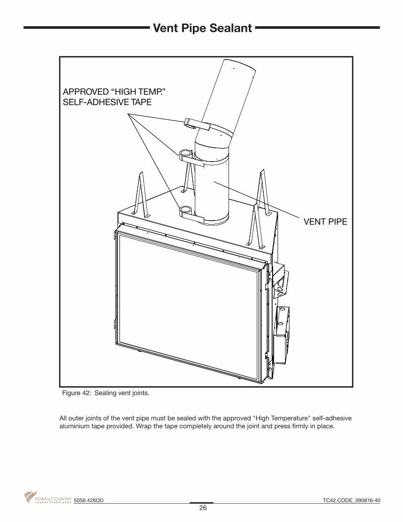
All outer joints of the vent pipe must be sealed with the approved "High Temperature" self-adhesive aluminium tape provided. Wrap the tape completely around the joint and press firmly in place.
APPROVED “HIGH TEMP.” SELF-ADHESIVE TAPE
VENT PIPE
Figure 42: Sealing vent joints.
26TC42.CODE_090816-405056.426OD
Vent Pipe Sealant
27TC42.CODE_090816-40 5056.426OD
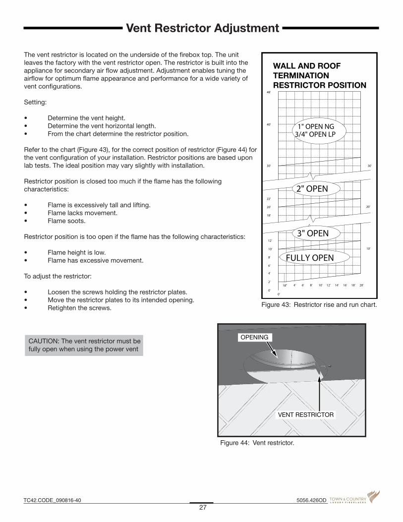
CAUTION: The vent restrictor must be fully open when using the power vent
Vent Restrictor Adjustment
The vent restrictor is located on the underside of the fi rebox top. The unit leaves the factory with the vent restrictor open. The restrictor is built into the appliance for secondary air fl ow adjustment. Adjustment enables tuning the airfl ow for optimum fl ame appearance and performance for a wide variety of vent confi gurations.
Setting:
• Determinetheventheight.• Determinetheventhorizontallength.• Fromthechartdeterminetherestrictorposition. Refer to the chart (Figure 43), for the correct position of restrictor (Figure 44) for the vent confi guration of your installation. Restrictor positions are based upon lab tests. The ideal position may vary slightly with installation.
Restrictor position is closed too much if the fl ame has the following characteristics:
• Flameisexcessivelytallandlifting.• Flamelacksmovement.• Flamesoots.
Restrictor position is too open if the fl ame has the following characteristics:
• Flameheightislow.• Flamehasexcessivemovement. To adjust the restrictor:
• Loosenthescrewsholdingtherestrictorplates.• Movetherestrictorplatestoitsintendedopening.• Retightenthescrews.
WALL AND ROOFTERMINATIONRESTRICTOR POSITION
12'
10'
30'
40'
48'
6'
4'
2'
0'
8'
30'
18" 4'
20'
22'
18'
20'
FULLY OPEN
3" OPEN
2" OPEN
3/4" OPEN LP
10'
0'
1" OPEN NG
6' 8' 10' 12' 14' 16' 18' 20'
Figure 43: Restrictor rise and run chart.
OPENING
VENT RESTRICTOR
Figure 44: Vent restrictor.
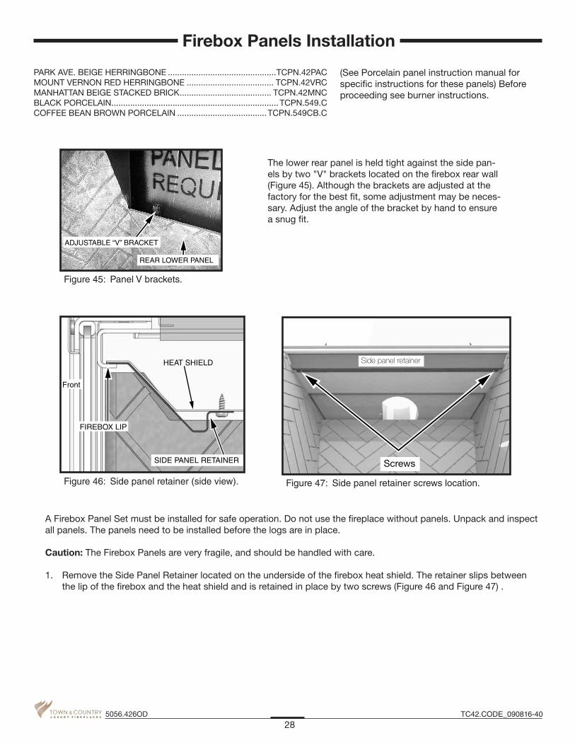
The lower rear panel is held tight against the side pan-els by two "V" brackets located on the firebox rear wall (Figure 45). Although the brackets are adjusted at the factory for the best fit, some adjustment may be neces-sary. Adjust the angle of the bracket by hand to ensure a snug fit.
ADJUSTABLE “V” BRACKET
REAR LOWER PANEL
Figure 45: Panel V brackets.
A Firebox Panel Set must be installed for safe operation. Do not use the fireplace without panels. Unpack and inspect all panels. The panels need to be installed before the logs are in place.
Caution: The Firebox Panels are very fragile, and should be handled with care.
1. Remove the Side Panel Retainer located on the underside of the firebox heat shield. The retainer slips between the lip of the firebox and the heat shield and is retained in place by two screws (Figure 46 and Figure 47) .
PARK AVE. BEIGE HERRINGBONE ..............................................TCPN.42PACMOUNT VERNON RED HERRINGBONE ..................................... TCPN.42VRCMANHATTAN BEIGE STACKED BRICK ....................................... TCPN.42MNCBLACK PORCELAIN ....................................................................... TCPN.549.CCOFFEE BEAN BROWN PORCELAIN ......................................TCPN.549CB.C
(See Porcelain panel instruction manual for specific instructions for these panels) Before proceeding see burner instructions.
HEAT SHIELD
FIREBOX LIP
SIDE PANEL RETAINER
Front
Figure 46: Side panel retainer (side view).
28TC42.CODE_090816-405056.426OD
Firebox Panels Installation
Screws
Side panel retainer
Figure 47: Side panel retainer screws location.

2. Install the Lower Rear Panel (Figure 48).
3. Install the right side panel by inserting the bottom of the panel in first and then angling it up into position. It may be necessary to push the firebox shield up to allow panel to move freely into place.
4. Install the Rear Upper Panel on top of the lower rear panel.
5. Install the Left Side Panel by inserting the bottom of the panel in first and then angling it up into position.
6. Re-install the Side Panel Retainer.
7. Install the Left and Right Front Panels (Figure 48).
Rear upperpanel
Left sidepanel
Right sidepanel
Right frontpanel
Left frontpanel
Rear lowerpanel
(HERRINGBONE PANEL SET SHOWN)
Figure 48: TC42 outdoor panel placement.
29TC42.CODE_090816-40 5056.426OD

LIGHTING INSTRUCTIONS1. STOP! Read the safety information above on this label.2. This appliance is equipped with an ignition device which
automatically lights the pilot. Do not try to light the pilot by hand.
3. Push the "On/ Off" switch to the fi replace Off.4. Allow suffi cient length of time (minimum 5 minutes) for any
gas in the combustion chamber to escape. If you still smell gas, STOP! Follow "B" in the safety information above on this label. If you don't smell gas, go to the next step.
WARNING: If you do not follow these instructions exactly, a fi re or explosion may result causing property damage, personal injury or loss of life.
A. This appliance is equipped with an ignition device which auto-matically lights the pilot. Do not try to light the pilot by hand.
B. BEFORE LIGHTING smell all around the appliance area for gas. Be sure to smell next to the fl oor because some gas is heavier than air and will settle on the fl oor.
WHAT TO DO IF YOU SMELL GAS: - Do not try to light any appliance. - Do not touch any electric switch; do not use any phone in your
FOR YOUR SAFETY READ BEFORE LIGHTING
5. Push the "On/ Off" switch to turn the fi replace on. - If the burner does not light, repeat steps 4 through 6. - If the burner will not light or stay lit after several tries,push
the "On/ Off" switch to the fi replace off and call your service technician or gas supplier.
Note: Suffi cient time must be allowed for air to escape from lines if the unit is being lit for the fi rst time.
building. - Immediately call your gas supplier from a neighbour's phone.
Follow the gas supplier's instructions. - If you cannot reach your gas supplier, call the fi re depart-
ment.C. Use only your hand to push in or turn the gas control knob.
Never use tools. If the knob will not push in or turn by hand, don't try to repair it, call a qualifi ed service technician. Force or attempted repair may result in a fi re or explosion.
D. Do not use this appliance if any part has been under water. Immediately call a qualifi ed service technician to inspect the appliance & to replace any part of the control system & any gas control which has been under water.
130312 5051.174 5-TC42OD
Hot while in operation. Do not touch. Severe burns may result. Keep children, clothing, furniture, gasoline and other liquids having fl ammable vapours away. Keep burner and control compartment clean. See installation and operating instructions accompanying the appliance.
CAUTION:
L'appareil est chaud lorsqu'il fonctionne. Ne pas toucher l'appareil. Risque de brûlu-res graves. Serveiller les enfants. Garder les vêtements, le meubles, l'essence ou autres liquides produisant des vapeurs infl ammables loin de l'appareil. S'assurer que le brûleur et le compartiment des commandes sont propres. Voir les instructions d'installation et d'utilisation qui accompagnent l'appareil.
ATTENTION:
TO TURN OFF GAS TO APPLIANCE1. Push the "on/ off" switch to the "Off" position. 2. Turn off all electric power to the appliance if service is to be
performed or for extended shutdown.
Due to high surface temperatures, keep children, clothing and furniture away. Keep burner and control compartment clean. See installation and operating instructions accompanying the appliance.
A cause de la temperature elevee des parios, tenir eloignes les enfants, les vetements et les meubles. Maintenir propres le bruleur et le compartiment de commande. Voir les instructions relatives a l'installation et au fonctionnement qui accompagnent l'appareil.
When lit for the first time, the fireplace will emit a slight odour for a couple of hours. This is due to the curing of paints, sealants and lubricants used in the manufacturing process. This condition is temporary. Open doors and windows to ventilate the area. Odour caused by the curing process may cause discomfort to some individuals.
It is normal for fireplaces fabricated of steel to give off some expansion and/or contraction noises during the start up or cool down cycle. Similar noises are found with your furnace heat exchanger or cook stove oven.
30TC42.CODE_090816-405056.426OD
Lighting Instructions
First Fire

CAUTION: Turn off gas and electrical power supply (if applicable) and allow ample time for unit to cool before servicing appliance. It is recommended that the fireplace and its venting should be inspected at least once a year by a qualified service person.
Glass Panel:
Warning: Do not operate fireplace with glass panel removed, cracked or broken. Replacement of the glass panel should be done by a licensed or qualified service person.
Do not strike or otherwise impact the glass in anyway that may cause it to break. If the glass becomes cracked or broken it must be replaced before using the fireplace. Replacement glass can be obtained from your nearest Town & Country Fireplaces dealer. The size required is 42" x 36" x 5mm. Use ceramic glass only. Do not substitute with any other type.
To remove broken glass, remove window frame as noted in “Window Frame Removal” on page 7.
Unclip the Glass Retainer Clips located at the top and sides of the Window Frame. Pull the top edge of the glass out of the frame first, then lift it up and out of the bottom edge.
Install the new piece of glass with the gasket into the frame so that the thicker bead of gasket faces the fireplace.
Re-install glass retaining clips.
Annual Inspection:
a) Remove glass panel and inspect the decorative burner media (such as logs, pebbles, glass etc) for soot build up. If excessive build up of soot is present, have a qualified service person inspect and adjust the unit for proper combus-tion. Clean the decorative media and use a brush or vacuum cleaner to clean the burner, paying close attention to the burner ports.
b) Inspect burner. It must be replaced prior to the appliance being put into operation if it is evident the burner is dam-aged. If damaged, replace with only Town and Country products.
c) Check the pilot system for proper flame size and operation. Clean pilot free of soot, dust or any other deposits. See Figure 31 on page 17
d) Check that the vent pipe and vent terminal are open and free from blockage or debris. If the venting is disassembled for cleaning, it must be properly assembled and re-sealed. Refer to VENTING section for proper procedure.
e) Check glass panel gasket, replace if necessary. It is important that the glass seal be maintained in good condition.
f) Check and replace batteries as needed.
Note: The appliance area must be kept clear and free from combustible materials, gasoline and other flammable vapours and liquids.
Periodically:
a) Viewing glass may be cleaned as necessary with fireplace glass cleaner.b) Exterior finish may be cleaned with mild soap and water.
CAUTION:Do not use abrasive cleaners on glass or any other part of the fireplace.
Do not clean glass when hot.
31TC42.CODE_090816-40 5056.426OD
Maintenance

(WHEN ORDERING, INCLUDE PART NUMBER WITH DESCRIPTION)
#1 TC42 OD BODY ASSEMBLY 1a FIREBOX SHIELD (c/w insulation) 1b FLUE DAMPER 1c FIREBOX REAR SHIELD 1d SPRING LATCH ASSEMBLY(2) 1e CONTROL ASSEMBLY HOLDER 1f BRICK PANEL RETAINER
#2 GLASS ASSEMBLY 2a REPLACEMENT GLASS (c/w gasket)
ITEM DESCRIPTION PART NO.
#1 TC42 OUTDOOR BODY ASSM. ....................... TC42.CODE
#2 GLASS ASSM .......................................... GLAS.2086ASSY
#3 FRAMING KIT ............................................. TC42. ODFRKIT
ITEM DESCRIPTION PART NO.
#4 PANEL SETS PARK AVE. BEIGE HERRINGBONE ................ TCPN.42PAC2 MT.VERNON RED HERRINGBONE ................. TCPN.42VRC2 MANHATTAN BEIGE STACKED BRICK .......... TCPN.42MNC2 MADISON ......................................................... TCPN.42MSD BLACK PORCELAIN ............................................TCPN.549.C CB BROWN PORCELAIN ...............................TCPN.549CB.C
KIT CONTENTS:
#3 FRAMIMG KIT 3a STEEL STUDS
#4 PANEL SETS 4a PANEL, LEFT SIDE 4b PANEL, UPPER 4c PANEL, RIGHT SIDE 4d PANEL, LEFT BASE 4e PANEL, RIGHT BASE 4f PANEL, LOWER BACK
1a
#1
1b
1c
1d
2a
4a
4c
4f
4b
4d4e
#3
#2
HONEYWELL CONTROL ASSEMBLY - page 33
#4
3a
1e
1f
32TC42.CODE_090816-405056.426OD
Replacement Parts

1a
1k
1h
1e
1d
1c
1b
1l
#1
#2
#3
#4
2a
2e
2d2c
2b
1j
1g
1m
(WHEN ORDERING, INCLUDE PART NUMBER WITH DESCRIPTION)
ITEM DESCRIPTION PART NO.
#1 CONTROL ASSEMBLY KIT ................................ TCRP.9000
#2 BULKHEAD ASSEMBLY KIT .............................. TCRP.8133
#3 CONTROL BOX KIT ................................. TCRP.92762WLD
#4 TEST FITTING ....................................................... 5019.104
#1 CONTROL ASSEMBLY KIT 1a VALVE c/w FITTINGS 1b 1/4" FLEX TUBE 1c 1/2" FLEX TUBE 1d CONTROL MOUNTING BRACKET 1e IGNITION MODULE 1g ELECTRICAL TRANSFORMER 1h PRESSURE TEST ASSEMBLY 1j TC36ST PRESSURE TEST PLATE 1k TC36ST LOCKING PLATE 1l WING NUTS (2) 1m TRANSFORMER BOX COVER PLATE REMOTE RECEIVER (not shown)
KIT CONTENTS:
#2 BULKHEAD ASSEMBLY KIT 2a INLET PLATE 2b INLET PLATE GASKET 2c ELEC BULKHEAD GASKET 2d 1/2” BULKHEAD FITTING 2e 1/4” BULKHEAD FITTING
#3 CONTROL BOX KIT
#4 TEST FITTING
33TC42.CODE_090816-40 5056.426OD
Replacement Parts – Honeywell Control System
MVMV
PV/MV
PV
GND
PV/MV
PV
24VACCOM24VACHOT
TRANSFORMER
PILOT
BLACK
MODULEHONEYWELL VALVE
BLAC
K
WHITE
WH
ITE
ORANGE
ORA
NG
E(L
OA
D)
WH
ITE
SPARK/FLAMESENSOR WIRE
24VAC
GREEN
115VAC60HzSINGLE PHASEGROUND
LINE
NEUTRAL
115VAC60HzSINGLE PHASE
SWITCH(NOT SUPPLIED)
GROUND
LINE
NEUTRAL
LIGHT LIGHT
SWITCH(NOT SUPPLIED)
IF EQUIPPED WITH LIGHTS
BLACK
WHITE
GREEN
BLACK
WHITE
GREEN
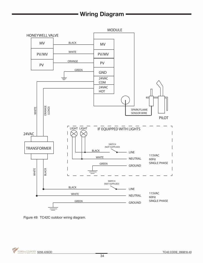
Figure 49: TC42C outdoor wiring diagram.
34TC42.CODE_090816-405056.426OD
Wiring Diagram

WALL SHIELD / CEILING FIRESTOPTCVT.THIMA - OPTIONAL
VERTICALTERMINATION CAPTCVT.9365
ROOF SUPPORTBRACKETTCVT.93915
STORM COLLARTC42.90665
WALL SHIELD / CEILING FIRESTOPTCVT.THIMA
WALLTERMINALTCVT.9360
WALLSHIELD/CEILINGFIRESTOP THIMBLETCVT.THIMA
Roof Termination Kit
Wall Termination Kit Wall Shield Ceiling Firestop Thimble
Figure 50: Ceiling firestop thimble.
16 1/2"
16 1/2"
9 5/8"
Figure 51: Wall termination kit.
16 1/2"
9"
Figure 52: Roof termination kit.
35TC42.CODE_090816-40 5056.426OD
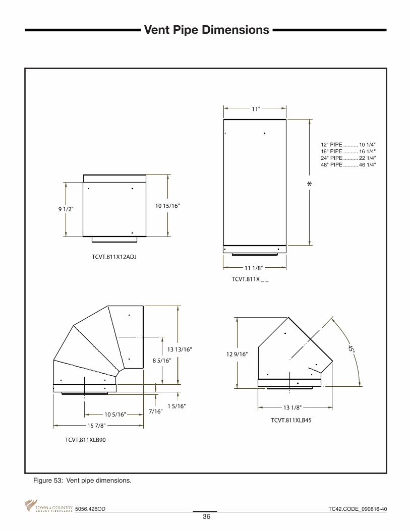
12" PIPE .......... 10 1/4"18" PIPE .......... 16 1/4"24" PIPE .......... 22 1/4"48" PIPE .......... 46 1/4"
Vent Pipe Dimensions
45°
11"
9 1/2" 10 15/16"
10 5/16"
15 7/8"
7/16"1 5/16"
8 5/16"
13 13/16"12 9/16"
13 1/8"
*
11 1/8"
TCVT.811X12ADJ
TCVT.811XLB45
TCVT.811XLB90
TCVT.811X _ _
Figure 53: Vent pipe dimensions.
36TC42.CODE_090816-405056.426OD

1 1/4”11 3/8”
10 7/8”
B
A
C
1 1/4”
1 1/4”
16 1/16”
6 1/8”
B
A
C
1 1/4”
20"
1 1/4” 18 3/4” B
A
20”
1 1/4”
Figure 54: Vent offsets.
ADDING AN ADJUSTABLE SECTION TO PIPE WILL INCREASE OFFSET BY 2 1/8" TO 6 3/4"
ADDING AN ADJUSTABLE SECTION TO PIPE WILL INCREASE OFFSET BY 2 1/8" TO 6 3/4"
ADDING AN ADJUSTABLE SECTION TO PIPE WILL INCREASE OFFSET BY 3" TO 9 1/2"
A B
12” PIPE 29”
18” PIPE 35”
24” PIPE 41”
48” PIPE 65”
A B C
12” PIPE 13 7/16” 23 1/4”
18” PIPE 17 9/16” 27 5/8”
24” PIPE 21 7/8” 31 3/4”
48” PIPE 38 3/4” 44 7/8”
A B C
12" PIPE 18 5/8" 18"
18" PIPE 22 7/8" 22 3/8"
24" PIPE 27 1/8" 26 1/2"
48" PIPE 44 1/16" 43 1/2"
Vent Offset Chart
37TC42.CODE_090816-40 5056.426OD

WN#200078 ETL#4001507
FOR OUTDOOR USE ONLY / POUR USAGE EXTÉRIEUR SEULEMENTElectrical rating: 115v, 60hz, 1.5 A / Note électrique: 115v, 60hz, 1.5 A. This appliance equipped for altitudes 0 - 4500 ft. (0 - 1372 m) / Cet unité est conçu pour des altitudes variant entre 0 - 4500 pieds (0 - 1372 m). This appliance must be installed in accordance with local codes, if any; if none, follow the current CAN/CGA-B149 (Canada), or ANSI Z223.1 (USA) Installation Codes. Installer l’appareil selon les codes ou règlements locaux, ou, en l’absence de tels règlements, selon les codes d’installation CAN/CGA-B149 (Canada), or ANSI Z223.1 (USA) en vigeur. The appliance, when installed, must be electrically grounded in accordance with local codes or, in the absence of local codes, with the Canadian Electrical Code, CSA C22.1 or with the National Electrical Code, ANSI/NFPA 70. L’appareil, une fois installé, doit être connecté électriquement à la terre conformément aux codes locaux ou, en l’absence de codes locaux, avec le Code canadien de l’électricité,CSAC22.1 ou avec le National Electrical Code,ANSI /NFPA70.
WARNING: Do not store or use gasoline or other fl ammable vapors or liquids in the vicinity of this or any other appliance. An LP cylinder not connected for use shall not be stored in the vicinity of this or any other appliance.AVERTISSEMENT : Ne stockez pas ou utilisez l’essence ou d’autres vapeurs infl ammables ou des liquides aux alentours de ceci ou un autre appareil. Un cylindre LP non connecté pour l’utilisation ne sera pas stocké aux alentours de ceci ou un autre appareil.
FOR USE WITH GLASS DOORS CERTIFIED WITH THE APPLIANCE ONLY / POUR UTILISATION UNIQUEMENT AVEC LES PORTES IN VERRE CERTIFIÉES AVEC L’APPAREIL
MINIMUM CLEARANCES TO COMBUSTIBLES / CLAIRANCES MINIMALES AVEC LES COMBUSTIBLE Left and Right side are determined when facing the front of the appliance. / Les côtés droit et gauche se déterminent
en se mettant devant l’appareil et en lui faisant face.
Top, Back and Side Standoffs / Sommet, Arrière et Côté Butée 0 in./ 0 po. (0 mm) Sidewall to Appliance / Du mur latéral a l’appareil 4 in./ 4 po. (102 mm) Ceiling to Appliance / Plafond a l’appareil 24 in./ 24 po. (610 mm) Mantel to Appliance / Du manteau al’appareil *9 in./ 9 po. (229 mm) Maximum Mantel Extension / Allongement maximum du manteau *12 in./ 12 po. (305 mm) *See Installation Manual for more detail / Voyez des Directive
de l’Installation pour plus détaux. Mantel Supports / Supports du manteau 4 in./ 4 po. (102 mm) Vent Pipe / Déchargez le Tuyau 1.75 in./ 1.75 po. (45 mm)
FOR USE WITH/ NATURAL GAS/ LP GAS/EN CASE D’EMPLOI AVEC: DU GAZ NATUREL DU GAZ LPMinimum supply pressure / Pression minimum d’alimentation: 5.0 in/wc / 5.0 po/c.e. 12.5 in/wc / 12.5 po/c.e.(For the purpose of input adjustment / dans le but de régler l’alimenation) (1.25 kPa) (3.11 kPa)Maximum supply pressure / Pression maximum d’alimentation: 13.9 in/wc / 13.9 po/c.e. 13.9 in/wc / 13.9 po/c.e. (3.45 kPa) (3.45 kPa)Manifold pressure / Pression de la tuyauterie: Maximum 3.8 in/wc / 3.8 po/c.e. 11.0 in/wc / 11.0 po/c.e. (0.95 kPa) (2.74 kPa)Orifi ce Size / Diametre de l’injectuer: # 25 (3.8 mm) 3/32” (2.38 mm)Input BTU/hr (kW) / Entree BTU/h (kW): Max.: 61,000 (17.9) Max.: 61,000 (17.9) Min.: 46,200 (13.5) Min.: 46,200 (13.5)
Pacifi c EnergyFireplace Products Ltd.
Duncan, British Columbia, Canada
WH-
MADE IN CANADAFABRIQUE AU CANADA
This Appliance is Equipped For Use With /Cet Appareil est Équipé Pour Utilise Avec :
NATURAL GASGAZ NATURELCertifi ed for / Certifi é pour Canada and U.S.A.
290212 5050.7209 1-TC42OD-C
VENTED OUTDOOR GAS FIREPLACE - NOT FOR USE WITH SOLID FUEL, FOYER AU GAZ À ÉVACUATION - NE PAS UTILISER AVEC DU COMBUSTIBLE SOLIDEANSI Z21.97- 2010 Outdoor Decorative Gas FireplacesCAN/CGA CR97- 003 Outdoor Gas Fireplaces
WARNING: Improper installation, adjustment, alteration, service or maintenance can cause injury or property damage. Refer to the owner’s information manual provided with this appliance. For assistance or additional information, consult a qualifi ed installer, service agency or the gas supplier.AVERTISSEMENT: Une installation, un réglage, une modifi cation, une réparation ou un entretien mal effectué peut causer des dommages matériels ou des blessures. Voir la notice de l’utilisateur qui accompgne l’appareil. Pour de l’aide ou des renseignements supplémentaires, consultez un installateur, un technicien agréé ou le fournisseur de gaz.
LP-GASLP GAZ
MODEL/MODELE:TC42ODSERIES/SERIE: C
Accepted for UseCity of New York
Department of BuildingsMEA 55-07-EPacifi c Energy
Fireplace Products Ltd.
NOTE: The Rating Label is located on a plate found in a slot between the left hand side lintel and the left hand side window frame. This plate is attached to the left side casing with a cable.
Rating Label Location
38TC42.CODE_090816-405056.426OD

39TC42.CODE_090816-40 5056.426OD

Printed in Canada
© 2016 Copyright Pacific Energy Fireplace Products LTD
Reproduction, adaptation, or translation without prior written permission is prohibited, except as allowed under the copyright laws.
www.townandcountryfireplaces.net2975 Allenby Rd., Duncan, BC V9L 6V8
For Technical Support, please contact your retailer.