500 interchange design - pages · 500 interchange design january 2018 5-3 distance. similarly, on...
TRANSCRIPT

500 Interchange Design
January 2018
Table of Contents 501 Interchange Design ............................................................................................. 5-1
501.1 General ............................................................................................................................. 5-1 501.2 Interchange Type .............................................................................................................. 5-1
501.2.1 General ...................................................................................................................... 5-1 502 Interchange Design Considerations .................................................................. 5-2
502.1 Determination of Interchange Configuration ..................................................................... 5-2 502.2 Approaches to the Structure ............................................................................................. 5-2
502.2.1 Alignment, Profile and Cross Section ........................................................................ 5-2 502.2.2 Sight Distance ........................................................................................................... 5-2
502.3 Interchange Spacing ......................................................................................................... 5-3 502.4 Uniformity of Interchange Patterns ................................................................................... 5-3 502.5 Route Continuity................................................................................................................ 5-3 502.6 Signing and Marking ......................................................................................................... 5-3 502.7 Basic Number of Lanes ..................................................................................................... 5-3 502.8 Coordination of Lane Balance and Basic Number of Lanes ............................................. 5-4 502.9 Auxiliary Lanes .................................................................................................................. 5-4 502.10 Lane Reductions ............................................................................................................... 5-4 502.11 Weaving Sections ............................................................................................................. 5-4
503 Interchange Ramp Design .................................................................................. 5-5
503.1 General ............................................................................................................................. 5-5 503.2 Ramp Design Speed ......................................................................................................... 5-5
503.2.1 Diamond Ramp Design Speeds ................................................................................ 5-5 503.2.2 Loop Ramp Design Speeds ...................................................................................... 5-5 503.2.3 Directional Ramp Design Speeds ............................................................................. 5-6
503.3 Vertical Alignment ............................................................................................................... 5-6 503.4 Horizontal Alignment ........................................................................................................... 5-6 503.5 Ramp Terminals .................................................................................................................. 5-7
503.5.1 General Considerations ............................................................................................. 5-7 503.5.2 Left-hand Entrances and Exits .................................................................................. 5-7 503.5.3 Distance Between Successive Ramp Terminals ....................................................... 5-7
503.6 Single-Lane Ramp Terminals ........................................................................................... 5-7 503.6.1 Terminal Classification ............................................................................................ 5-8 503.6.2 Single-Lane Entrance Terminals ............................................................................. 5-8 503.6.2.1 High-Speed ................................................................................................ 5-8 503.6.2.2 Low-Speed ................................................................................................ 5-8 503.6.3 Single-Lane Exit Terminals ..................................................................................... 5-9 503.6.3.1 High-Speed ................................................................................................ 5-9 503.6.3.2 Low-Speed ................................................................................................ 5-9 503.6.4 Superelevation at Terminals ...................................................................................... 5-9 503.6.5 Terminals on Crest Vertical Curves ......................................................................... 5-10
503.7 Ramp At-Grade Intersections ........................................................................................... 5-10 504 Collector - Distributor (C-D) Roads .................................................................. 5-10
504.1 Use of C-D Roads ............................................................................................................. 5-10 504.2 Design of C-D Roads ........................................................................................................ 5-10 504.3 C-D Road Entrance and Exit Terminals ............................................................................ 5-10

500 Interchange Design
January 2018
505 Multi-lane Ramp & Roadway Terminals and Transitions ............................... 5-11
505.1 Multi-lane Entrance Ramps and Converging Roadways .................................................. 5-11 505.1.1 General .................................................................................................................... 5-11 505.1.2 Lane Balance and Continuity .................................................................................. 5-11 505.1.3 Inside Merges .......................................................................................................... 5-11 505.1.4 Preferential Flow ...................................................................................................... 5-11 505.1.5 Horizontal Curvature ................................................................................................ 5-12 505.1.6 Crest Vertical Curves ............................................................................................... 5-12 505.1.7 Superelevation and Joint Location .......................................................................... 5-12
505.2 Multi-lane Exit Ramps and Diverging Roadways ............................................................ 5-12 505.2.1 General .................................................................................................................... 5-12 505.2.2 Lane Balance and Continuity .................................................................................. 5-12 505.2.3 Terminal Design ...................................................................................................... 5-13 505.2.4 Horizontal Curvature ................................................................................................ 5-13 505.2.5 Crest Vertical Curves ............................................................................................... 5-13 505.2.6 Superelevation and Joint Location .......................................................................... 5-13
505.3 Four Lane Divided to Two Lane Transition ....................................................................... 5-13 506 Service Roads.................................................................................................... 5-14
506.1 Use of Service Roads ....................................................................................................... 5-14 506.2 Design of Service Roads ................................................................................................ 5-14
550 Requests for New or Revised Access - Interstate Highways or Other Freeways ................................................................................................................................... 5-14
550.1 General ............................................................................................................................. 5-14 550.2 Access Point Request Document ..................................................................................... 5-15
550.2.1 Interchange Operations Study (IOS) ....................................................................... 5-17 550.2.2 Safety Improvements on Interstate or Other Freeways .......................................... 5-18
550.3 Study Methodology ........................................................................................................... 5-18 550.3.1 General .................................................................................................................... 5-18 550.3.2 Constrained Traffic .................................................................................................. 5-19 550.3.3 Diagrams and Plans ................................................................................................ 5-19
550.4 Environmental Studies ...................................................................................................... 5-19 550.5 Review Process ................................................................................................................ 5-19
List of Figures .......................................................................................................... 5-20

500 Interchange Design
January 2018 5-1
501 Interchange Design
501.1 General An interchange is defined as a system of interconnecting roadways in conjunction with one or more grade separations that provides for the movement of traffic between two or more roadways or highways on different levels. Interchanges are utilized on freeways and expressways where access control is important. They are used on other types of facilities only where crossing and turning traffic cannot be accommodated by a normal at-grade intersection. An Interchange Justification Study may be necessary.
501.2 Interchange Type
501.2.1 General The most commonly used types of interchanges are the diamond, cloverleaf and directional. The diamond interchange is the most common type where a major facility intersects a minor highway. The design allows free-flow operation on the major highway but creates at-grade intersections on the minor highway with the ramps. The capacity is limited by the at-grade intersections on the minor highway. Variations of the diamond interchange include the Tight Urban Diamond Interchange (TUDI) and the Single Point Urban Interchange (SPUI). The characteristics of the TUDI include closely spaced ramp intersections, typically within 250 ft. to 400 ft. of each other, with side-by-side left turn lanes on the minor highway that extend beyond the first ramp intersection. Special signal phasing allows queuing of vehicles outside the ramp intersections and minimizes queuing of vehicles between the ramp intersections. The SPUI aligns the left turn movements of the exit ramps opposite one another to form a single intersection at the center of the grade separation structure. Both SPUIs and TUDIs are more compact than a standard diamond, but are significantly more costly to construct. Cloverleaf or partial cloverleaf designs may be used in lieu of a diamond when development or other physical conditions prohibit construction in a quadrant, or where heavy left turns are involved. A continuous flow design is required where two major facilities intersect. In this case, a full cloverleaf interchange is the minimum design that can be used. The designer should consider collector-distributor roads in conjunction with cloverleaf interchanges to minimize weaving. However, full cloverleafs have deficiencies which need to be addressed before being chosen as the interchange type. Principle disadvantages are:
The inherent weaving maneuver generated and the short weaving length available. Large trucks may not be able to operate efficiently on the smaller curve radii on the associated
loop ramps. Loop ramps are limited in capacity.
When Collector-Distributor roads are not used, a further disadvantage includes weaving on the main line, the double exit on the main line and problems associated with signing for the second exit. The full cloverleaf weaving maneuver is not objectionable when the left-turning movements are relatively light, but when the sum of traffic volumes on two adjoining loops approaches about 1,000 vehicles per hour, interference occurs, which results in a reduction in the speed of the mainline traffic. On low-volume full cloverleaf interchanges, the weaving length shown in Figure 503-1a should be provided. When the weaving volume in a particular weaving section exceeds 1,000 vehicles per hour, the quality of service on

500 Interchange Design
January 2018 5-2
the main facility deteriorates, generating a need to transfer the weaving section from the through lanes to a C-D road. For these reasons, full cloverleafs are discouraged. Directional interchanges are the highest type and most expensive. They permit vehicles to move from one major freeway to another major freeway at relatively fast and safe speeds.
502 Interchange Design Considerations
502.1 Determination of Interchange Configuration Interchange configurations are covered in two categories, “system interchanges” and “service interchanges.” The term “system interchange” is used to identify interchanges that connect two or more freeways, whereas the term “service interchange” applies to interchanges that connect a freeway to lesser facilities. Generally, interchanges in rural areas are widely spaced and can be designed on an individual basis without any appreciable effect from other interchanges within the system. However, the final configuration of an interchange may be determined by the need for route continuity, uniformity of exit patterns, single exits in advance of the separation structure, and elimination of weaving on the main facility, signing potential, and availability of right-of-way. Selecting an appropriate interchange configuration in an urban environment involves considerable analysis of prevailing conditions so that the most practical interchange configuration alternatives can be developed. Generally, in urban areas, interchanges are so closely spaced that each interchange may be influenced directly by the preceding or following interchange to the extent that additional traffic lanes may be needed to satisfy capacity, weaving and lane balance. Interchanges should provide for all movements, even when an anticipated turning movement volume is low. Once several alternates have been prepared for the system design, they can be compared on the following principles: (1) capacity, (2) route continuity, (3) uniformity of exit patterns, (4) single exits in advance of the separation structure, (5) with or without weaving, (6) potential for signing, (7) cost, (8) availability of right-of-way, (9) constructability, and (10) compatibility with the environment.
502.2 Approaches to the Structure
502.2.1 Alignment, Profile and Cross Section Traffic passing through an interchange should be afforded the same degree of utility and safety as that given on the approaching roadways. The design speed, alignment, profile and cross section in the interchange area should be consistent with those on the approaching highways. Four-lane roadways should be divided at interchanges with a non-traversable median to ensure that drivers use the proper ramps for left-turning maneuvers. At-grade left turns preferably should be accommodated within a suitably wide median.
502.2.2 Sight Distance Sight distance on the roadways through an interchange should be at a minimum the required stopping sight distance and preferably should be Decision Sight Distance (Figure 201-6), particularly along entrances and exits. The horizontal sight distance limitations of piers and abutments at curves usually present a more difficult problem than that of vertical limitations. With the minimum radius for a given design speed, the normal lateral clearances at piers and abutments of underpasses does not provide the minimum stopping sight

500 Interchange Design
January 2018 5-3
distance. Similarly, on overpasses with the sharpest curvature for the design speed, sight distance deficiencies result from the usual offset to the bridge railing. Above minimum radii should be used for curvature on roadways through interchanges. If sufficiently flat curvature cannot be used, the clearances to abutments, piers or bridge railing should be increased to obtain the proper sight distance, even though this involves increasing structure spans or widths.
502.3 Interchange Spacing Interchanges should be located close enough together to properly discharge and receive traffic from other highways or streets, and far enough apart to permit the free flow and safety of traffic on the main facility. In general, more frequent interchange spacing is permitted in urbanized areas. Minimum spacing is determined by weaving requirements, ability to sign, lengths of speed change lanes, and capacity of the main facility. Interchanges within urban areas should not be spaced closer than an average of 2 miles, in suburban sections an average of not closer than 4 miles, and in rural sections an average of not closer than 8 miles. In consideration of the varying nature of the highway, street or road systems with which the freeway or expressway must connect, the spacing between individual adjacent interchanges must vary considerably. In urban areas, the minimum distance between adjacent interchanges should not be less than 1 mile, and in rural areas not less than 3 miles. Spacing less than this have a detrimental effect on freeway operations.
502.4 Uniformity of Interchange Patterns Since interchange uniformity and route continuity are interrelated concepts, interchanges along a freeway should be reasonably uniform in geometric layout and general appearance to provide the appropriate level of service and maximum safety in conjunction with freeway operations. Except in highly special cases, all entrance and exit ramps should be on the right.
502.5 Route Continuity Route continuity is an extension of the principle of operational uniformity coupled with the application of proper lane balance and the principle of maintaining a basic number of lanes. The principle of route continuity simplifies the driving task in that it reduces lane changes, simplifies signing, delineates the through route and reduces the driver’s search for directional signing. Desirably, the through driver should be provided a continuous through route on which changing lanes is not necessary to continue on the through route. In maintaining route continuity, interchange configuration may not always favor the heavy traffic movement, but rather the through route. In this situation, heavy movements can be designed on flat curves with reasonably direct connections and auxiliary lanes.
502.6 Signing and Marking The safety, efficiency and clarity of paths to be followed at interchanges depend largely on their relative spacing, geometric layout and effective signing and marking. The location of and minimum spacing between ramp terminals depends to a large degree on whether or not effective signing can be provided. Signing and marking should conform to the OMUTCD.
502.7 Basic Number of Lanes The basic number of lanes is defined as a minimum number of lanes designated and maintained over a significant length of a route, irrespective of changes in traffic volume and lane balance needs. (The basic

500 Interchange Design
January 2018 5-4
number of lanes is a constant number of lanes assigned to a route, exclusive of auxiliary lanes, based on capacity needs of the section.)
502.8 Coordination of Lane Balance and Basic Number of Lanes Design traffic volumes and a capacity analysis determine the basic number of lanes to be used on the freeway and the minimum number of lanes on the ramps. The basic number of lanes should be established for a substantial length of freeway and should not be changed through pairs of interchanges, simply because there are substantial volumes of traffic entering or leaving the freeway. There should be continuity in the basic number of lanes. Auxiliary lanes should be provided for variations in traffic demand. After the basic number of lanes is determined for each roadway, the balance in the number of lanes should be checked on the basis of the following principles:
1. At entrances, the number of lanes beyond the merging of two traffic streams should not be less than the sum of all traffic lanes on the merging roadways minus one, but may be equal to the sum of all traffic lanes on the merging roadways.
2. At exits, the number of approach lanes on the roadway should be equal to the number of lanes on
the roadway beyond the exit, plus the number of lanes on the exit, minus one. Exceptions to this principle occur at cloverleaf loop ramp exits that follow a loop ramp entrance and at exits between closely spaced interchanges. In these cases, the auxiliary lane may be dropped in a single-lane exit with the number of lanes on the approach roadway being equal to the number of through lanes beyond the exit plus the lane on the exit.
3. The traveled way of the highway should be reduced by not more than one traffic lane at a time.
502.9 Auxiliary Lanes An auxiliary lane is the portion of the roadway adjoining the traveled way for speed change, turning, storage for turning, weaving and other purposes supplementary to through-traffic movement. An auxiliary lane may be provided to comply with the concept of lane balance, to comply with capacity needs or to accommodate speed changes, weaving and maneuvering of entering or exiting traffic.
502.10 Lane Reductions The basic number of mainline lanes should not be reduced through a “service interchange”. If a reduction in the basic number of lanes is warranted by a substantial decrease in traffic volume over a significant length of freeway, then it should be reduced between interchanges. The reduction should occur 2,000 to 3,000 ft. from the end of the acceleration taper of the previous interchange to allow for adequate signing. The end of the lane reduction should be tapered at a rate of 70:1. The lane reduction should occur on a tangent section of freeway, preferably within a sag vertical curve, and provide Decision Sight Distance, Figure 201-6, where possible. The lane reduction should also be on the right side of the freeway.
502.11 Weaving Sections Weaving sections are highway segments where the pattern of traffic entering and exiting at contiguous points of access results in vehicle paths crossing each other. Weaving sections may occur within an interchange, between closely spaced interchanges or on segments of overlapping routes.

500 Interchange Design
January 2018 5-5
Because weaving sections cause considerable turbulence which results in a reduction in capacity, interchange designs that eliminate weaving or remove it from the mainline by the use of C-D roads are desirable. The capacity of weaving sections may be seriously restricted unless the weaving section has adequate length, adequate width and lane balance. Refer to the Highway Capacity Manual for capacity analysis of weaving sections.
503 Interchange Ramp Design
503.1 General An interchange ramp is a roadway which connects two legs of an interchange. Ramp cross section elements are discussed in Section 303.1. Elements contributing to horizontal and vertical alignments are designed similar to any roadway (Section 200) once the ramp design speed has been determined.
503.2 Ramp Design Speed In order to design horizontal and vertical alignment features, a design speed must be determined for each ramp. Since the driver expects a speed adjustment on a ramp, the design speed may vary within the ramp limits. Figure 503-1 includes three ranges of ramp design speeds which vary with the design speed of the mainline roadway. The ramp design speed range is determined by engineering judgment based on several conditions:
1. The type of roadways at each end of the ramp and their design speeds,
2. The length of the ramp,
3. The terminal conditions at each end, and
4. The type of ramp (diamond, loop or directional). Design exceptions will be required for speed related design criteria that do not meet the following:
For directional ramps (roadways) that do not provide the minimum design speed given in Section 503.2.3.
For loop ramps on high-speed roadways that do not provide a minimum design speed of 25 mph (150-ft radius).
For all other ramps that, at a minimum, do not provide the lower range design speed of Figure 503-1.
503.2.1 Diamond Ramp Design Speeds Diamond ramps normally have a high speed condition at one end and an at-grade intersection with either a stop or slow turn (15 mph) condition at the other. Upper to middle range design speeds in Figure 503-1 are normal near the high speed facility with middle to lower range design speeds usually used closer to the at-grade intersection.
503.2.2 Loop Ramp Design Speeds Loop ramps may have a high speed condition at one end and, either a slow or high speed condition at the other. Loop ramps, because of their short radius, usually have design speeds in the lower range in the

500 Interchange Design
January 2018 5-6
middle and slow speed end of the ramp with middle range design speeds occasionally used nearer the high speed terminal. For design speeds, see Figure 503-1. The minimum loop ramp radius is 150 feet (50 m).
503.2.3 Directional Ramp Design Speeds Directional ramps (roadways) generally have high speed conditions at both ends. They are normally designed using a design speed falling into the upper range of Figure 503-1. The absolute minimum should be the middle range design speeds.
503.3 Vertical Alignment Maximum grades for vertical alignment cannot be as definitely expressed as for the highway, but should preferably not exceed 5 percent. General values of limiting upgrades are shown in Table 503-1, but for any one ramp the grades to be used are dependent upon a number of factors. These factors include the following:
1. The flatter the gradient on the ramp relative to the freeway grade, the longer the ramp will be.
2. The steepest grades should occur over the center part of the ramp. Grades at the terminal ends of the ramp should be as flat as possible.
3. Short upgrades of 7 to 8 percent permit good operation without unduly slowing down passenger
cars. Short upgrades of as much as 5 percent do not unduly affect trucks and buses.
4. Ramp grades and lengths can be significantly impacted by the angle of intersection between the two highways when the angle is 70 degrees or less. The direction and grade on the two highways may also have a significant impact.
5. Adequate sight distance is more important than a specific gradient control and should be favored
in design.
Table 503-1 Maximum Ramp Upgrades
Ramp Design Speed 25-30 mph
35-40 mph
45 mph and above
Desirable Grade (%) 5 4 3 Maximum Grade (%) 7 6 5
Note: Downgrades may exceed the table values by 2%, but should not exceed 8%.
503.4 Horizontal Alignment Horizontal alignment will be largely determined by the selected design speed and type of ramp. The horizontal alignment criteria found in Section 202 shall also apply to ramps. Check that the required horizontal stopping sight distance is provided. Use the allowed skew at the ramp terminal at-grade intersection to minimize curvature. Depending on the design speed and curvature, curve widening may be required on a two-lane ramp. See Section 301.1.3 and Figure 301-5c. The WB-62 [WB-19] design vehicle should be used for Interstate ramps.

500 Interchange Design
January 2018 5-7
503.5 Ramp Terminals The terminal of a ramp is that portion adjacent to the through traveled way, including speed change lanes, tapers and islands. Ramp terminals, as opposed to diverging roadways, require speed change lanes. Ramp terminals may be the at-grade type, as at the crossroad terminal of diamond or partial cloverleaf interchanges, or the free-flow type where ramp traffic merges with or diverges from high-speed through traffic at flat angles. Terminals are further classified as either single-lane or multi-lane and as either a taper or parallel type.
503.5.1 General Considerations While interchanges are custom designed to fit specific site conditions, it is desirable that the overall pattern of exits along the freeway have some degree of uniformity. It is desirable that all interchanges have one point of exit located in advance of the crossroad wherever practical. Because considerable turbulence occurs throughout weaving sections, interchange designs that eliminate weaving entirely or at least remove it from the mainline are desirable. Weaving sections may be eliminated from the mainline by the incorporation of C-D roadways or grade separating the ramps (braiding). Interchanges that provide all exit movements before any entrance movements will also eliminate weaving and are highly recommended.
503.5.2 Left-hand Entrances and Exits Left-hand entrances and exits are contrary to the concept of driver expectancy when intermixed with right-hand entrances and exits. Therefore, extreme care should be exercised to avoid left-hand entrances and exits in the design of interchanges. Because they are contrary to driver expectancy, special attention should be given to signing and the provision for decision sight distances to alert the driver an unusual condition exists.
503.5.3 Distance Between Successive Ramp Terminals In urban areas ramp terminals are often located in close succession. To provide sufficient weaving length and adequate space for signing, a reasonable distance should be provided between successive ramp terminals. Spacing between successive outer ramp terminals is dependent on the classification of the interchanges involved, the function of the ramp pairs (entrance or exit), and weaving potential. Minimum spacing for various ramp combinations are shown in Figure 503-1a. Where an entrance ramp is followed by an exit ramp, that absolute minimum distance between the successive noses is governed by weaving considerations. This spacing is not applicable to cloverleaf interchanges as the distances between entrance-exit ramps noses is dependent on loop ramp radii and other factors. When the distance between successive noses is less than 1,500 ft. the speed change lanes should be connected to provide an auxiliary lane to improve traffic flow over a relatively short section of the freeway.
503.6 Single-Lane Ramp Terminals This discussion is limited to terminals used for single-lane entrance and exit ramps only. See Section 505 for multi-lane transitions. Ohio’s standards currently permit a parallel exit terminal and tapered entrance terminal.

500 Interchange Design
January 2018 5-8
503.6.1 Terminal Classification Ohio uses two basic ramp terminal classifications. High-Speed Terminals (See Figures 503-2a, 503-2b and 503-2c, along with Figures 503-3a, 503-3b and 503-3c) - High-Speed terminals are intended for use on all Interstate highways and on other limited access freeways or expressways having similar design standards and a minimum mainline design speed of 50 mph. Low-Speed Terminals (See Figures 503-4a and 503-4b) - Low-Speed terminals (mainline design speeds of 45 mph or less) are intended for use on all other limited access expressways or other highways which have little or no access control except through an interchange area. Many of the features of Low-Speed terminals are applicable to a terminal of one ramp with another ramp. Low Speed terminals are also used with Low-Speed C-D Roads.
503.6.2 Single-Lane Entrance Terminals
503.6.2.1 High-Speed
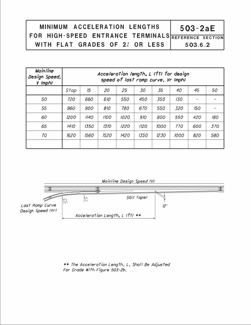
The typical single-lane entrance terminal consists of two parts, an acceleration lane and a taper. The acceleration lane allows the entering vehicle to accelerate to the freeway speed and evaluate gaps in the freeway traffic. The taper is provided for the entering vehicle to merge into the chosen gap in freeway traffic. The minimum taper rate is 50:1. The length of the acceleration lane varies depending on the design speed of the last ramp curve on the entrance ramp and the design speed of the mainline. Figure 503-2a provides the minimum lengths of acceleration lanes for entrance ramp terminals. When the average grade of the acceleration lane exceeds 3%, the acceleration length obtained from Figure 503-2a should be adjusted by the factor obtained from Figure 503-2b. The acceleration lane length is measured from the last entrance ramp curve point (PT or CS) to the point where the right edge of traveled way of the ramp is 12 feet from the right edge of the through traveled way of the freeway. Figure 503-2c illustrates the typical design of a single-lane entrance ramp terminal. If the entrance terminal results in an add-lane (no merge), delete the last 600’ of the 50:1 taper of Figure 503-2c. All other entrance terminal dimensions of Figure 503-2c remain the same. Referring to Figure 503-2c, when the required acceleration length (L from Figure 503-2a, adjusted to grade, Figure 503-2b) is less than the acceleration length provided by the 200 ft. spiral plus 650 ft. of the 50:1 taper, then a parallel acceleration length is not required and the terminal becomes the minimum acceptable design consisting of the 200 ft. spiral and the 1,250 ft. 50:1 taper.
503.6.2.2 Low-Speed
Figure 503-4a provides the Low-Speed Entrance Terminal designs for mainline design speeds equal to or less than 45 mph.

500 Interchange Design
January 2018 5-9
503.6.3 Single-Lane Exit Terminals
503.6.3.1 High-Speed
The typical single-lane exit terminal consists of two parts, a taper for maneuvering out of the through traffic lane and a deceleration lane to slow to the speed of the first curve on the ramp. All deceleration should occur on the full width deceleration lane and not on the mainline or the taper. The length of the deceleration lane varies depending on the design speed of the mainline and the design speed of first geometric control on the exit ramp, usually a horizontal curve but could be the stopping sight distance on a vertical curve or the back of an anticipated traffic queue. Figure 503-3a provides the minimum lengths of deceleration lanes for exit ramp terminals. When the average grade of the deceleration lane exceeds 3 percent, the deceleration length obtained from Figure 503-3a should be adjusted by the factor obtained from Figure 503-3b. The deceleration lane length is measured from the point where the taper reaches a width of 12 feet to the first point that governs the design speed of the exit ramp, usually the PC of the first curve. Figure 503-3c illustrates the typical design of a single-lane exit ramp terminal. The minimum deceleration length (Figure 503-3a) adjusted to grade (Figure 503-3b) shall be 800 ft.
503.6.3.2 Low-Speed
Figure 503-4b provides the Low-Speed Exit Terminal design for mainline design speeds equal to or less than 45 mph.
503.6.4 Superelevation at Terminals Superelevation at ramp terminals should be developed using the following guidelines:
1. The rate of superelevation at the entrance and exit nose shall be selected on the basis of the design speed of the ramp at the nose.
2. All transverse changes or breaks in superelevation shall be made at joint lines (See Standard
Construction Drawing BP-6.1). In the case of bituminous pavement, the superelevation breaks should occur in the same locations as they would in concrete pavement.
3. For High-Speed terminals, the transverse breaks in superelevation cross-slope shall not exceed a
differential of 0.032 at the mainline edge of traveled way or 0.050 at other locations. If a double break occurs on longitudinal joints less than 6 ft. apart, it shall not exceed a total differential of 0.032, if adjacent to the mainline, or 0.050 elsewhere. On Low-Speed terminals the transverse breaks in superelevation cross-slope shall not exceed a differential of 0.05 to 0.06.
4. For High-Speed terminals, the rate of rotation of a superelevated ramp pavement or speed
change lane pavement shall be in accordance with Section 202.4.
5. Where possible, the terminal area pavement and shoulder should slope away from the mainline pavement so that a minimum amount of water drains across the mainline pavement.

500 Interchange Design
January 2018 5-10
503.6.5 Terminals on Crest Vertical Curves
Mainline crest vertical curves in the vicinity of ramp terminals should be designed using decision stopping sight distances. Where a crest vertical curve occurs on an exit ramp at or near the nose, the crest vertical curve should be designed using the "upper range" design speeds of Figure 503-1.
503.7 Ramp At-Grade Intersections Ramp at-grade intersections are designed using much of the same criteria as outlined in Section 401 (the normal design vehicle for Interstate ramps is the WB-62 [WB-19]). However, one of the basic differences is the one-way nature of ramps and the fact that most traffic at ramp intersections is turning. Figure 503-5 shows the design of a typical uncurbed ramp intersection. Curbed returns are normally used in urban areas where space is more restricted. Intersection Sight Distance, Section 201.3, should be provided at all ramp at-grade intersections. Exit ramps may require multiple lanes at the crossroad intersection to provide additional storage and capacity. Figure 503-5a illustrates alternate ways to transition from a single lane exit ramp to two lanes. The additional lane is usually provided for the minor movement.
504 Collector - Distributor (C-D) Roads
504.1 Use of C-D Roads The reason for using C-D Roads is to minimize weaving problems and reduce the number of conflict points (merging and diverging) on the mainline. C-D Roads may be used within a single interchange, through two adjacent interchanges, or continuously through several interchanges.
504.2 Design of C-D Roads When a C-D Road is provided between interchanges, a minimum of two lanes should be used. Either one or two lanes may be used on C-D Roads within a single interchange. The cross section elements for one and two lane C-D Roads should be in accordance with the one lane and two lane directional roadways shown in Figure 303-1. The design speed of a C-D Road should normally be the same as the mainline design speed but may be reduced by not more than 10 mph. The separation between the mainline and C-D Road pavements should be designed to prevent, or at least discourage, indiscriminate crossovers. As a minimum, the separation should be wide enough to provide normal shoulder widths for both the mainline and C-D Road roadways plus a suitable median. Normally, a standard concrete barrier median is used since C-D Road separation often involves obstructions such as bridge parapets, piers or overhead sign supports. There may be isolated cases where a lesser type median may be used.
504.3 C-D Road Entrance and Exit Terminals Figure 504-1 shows both Low-Speed and High-Speed C-D Road entrance terminals. Three exit terminal lane conditions are shown on Figure 504-2. These terminal designs are to be applied to highways using High-Speed exit terminals. Superelevation at C-D Terminals shall be developed similar to that described in Section 503.6.4.

500 Interchange Design
January 2018 5-11
505 Multi-lane Ramp & Roadway Terminals and Transitions When two roadways converge or diverge, the less significant roadway should exit or enter on the right. Left-hand exits or entrances are contrary to driver expectancy and should be avoided wherever possible.
505.1 Multi-lane Entrance Ramps and Converging Roadways
505.1.1 General Figure 505-1a shows the design to be used for multi-lane entrance ramps and converging roadways. Converging roadways are defined as separate and nearly parallel roadways or ramps which combine into a single continuous roadway or ramp having a greater number of lanes beyond the nose than the number of lanes on either approach roadway. (Single-Lane Entrance Terminals should be used in lieu of Converging Roadway drawings when a speed change lane is required.) Figure 505-1b shows the specific design to be used for two-lane High-Speed entrance ramps. High-Speed Converging Roadways should be used when either or both of the Converging Roadways are mainline roadways of an expressway or freeway or if the design speed of converging directional ramps is 50 mph or higher. Low-Speed Converging Roadways should be used at the convergence of directional ramps within an interchange or at the convergence of interchange ramps with non-limited access roads or streets where design speeds are 45 mph or lower.
505.1.2 Lane Balance and Continuity In order to avoid inside merges, the number of mainline lanes plus converging lanes approaching the nose must be equal to the resultant number of lanes leaving the nose. To make this possible, it is often necessary to carry additional mainline lanes past the nose for an adequate distance prior to tapering back to the desired number of lanes. These details are shown in Figure 505-1a.
505.1.3 Inside Merges When using a taper type of multilane entrance ramp an “inside merge” is created with traffic traveling on both sides of the merging lanes. If either vehicle involved with the merging movement abandons the merge, traffic in the adjacent lanes could prevent the merging vehicles from escaping to the adjacent lanes. By contrast, the parallel type multilane entrance ramp, as shown in Figure 505-1a, allows the merging vehicle to escape to the right shoulder without any interference. For the above reasons, inside merges are not desirable.
505.1.4 Preferential Flow On Figure 505-1a, one roadway in each design is labeled PREFERENTIAL FLOW. This indicates the more important of the two approaching traffic flows. In selecting the preferential flow a designer must consider the effect of traffic volumes, number of lanes, sign route continuity and importance, vehicle speeds and roadway alignment. Lanes carrying the preferential flow are given the higher design treatment. When it is necessary to reduce a number of converging lanes or where an angular change in direction must occur, the design should favor the preferential flow.

500 Interchange Design
January 2018 5-12
505.1.5 Horizontal Curvature Horizontal curves of roadways approaching the terminal nose should conform to mainline roadway criteria in the case of mainline roadways and to ramp entrance terminal criteria in the case of ramps.
505.1.6 Crest Vertical Curves Crest vertical curves on constant-width roadways approaching the merging nose should be designed to provide sight distance consistent with the design speed of the roadway. Crest vertical curves from the merging nose forward to a point where pavement convergence ceases and to the converging portion of an approaching roadway where the number of lanes is being reduced in advance of the nose should be designed using the decision stopping sight distance shown in Figure 201-6. (See Figure 505-1a.) When design speeds differ on approaching roadways, the higher of the two design speeds shall be used in designing the crest vertical curve beyond the merging nose.
505.1.7 Superelevation and Joint Location Reference shall be made to Section 503.6.4 for superelevation requirements. Longitudinal joints should be located so they will coincide with and define the lane lines. Reference should be made to Standard Construction Drawing BP-6.1 for type and location.
505.2 Multi-lane Exit Ramps and Diverging Roadways
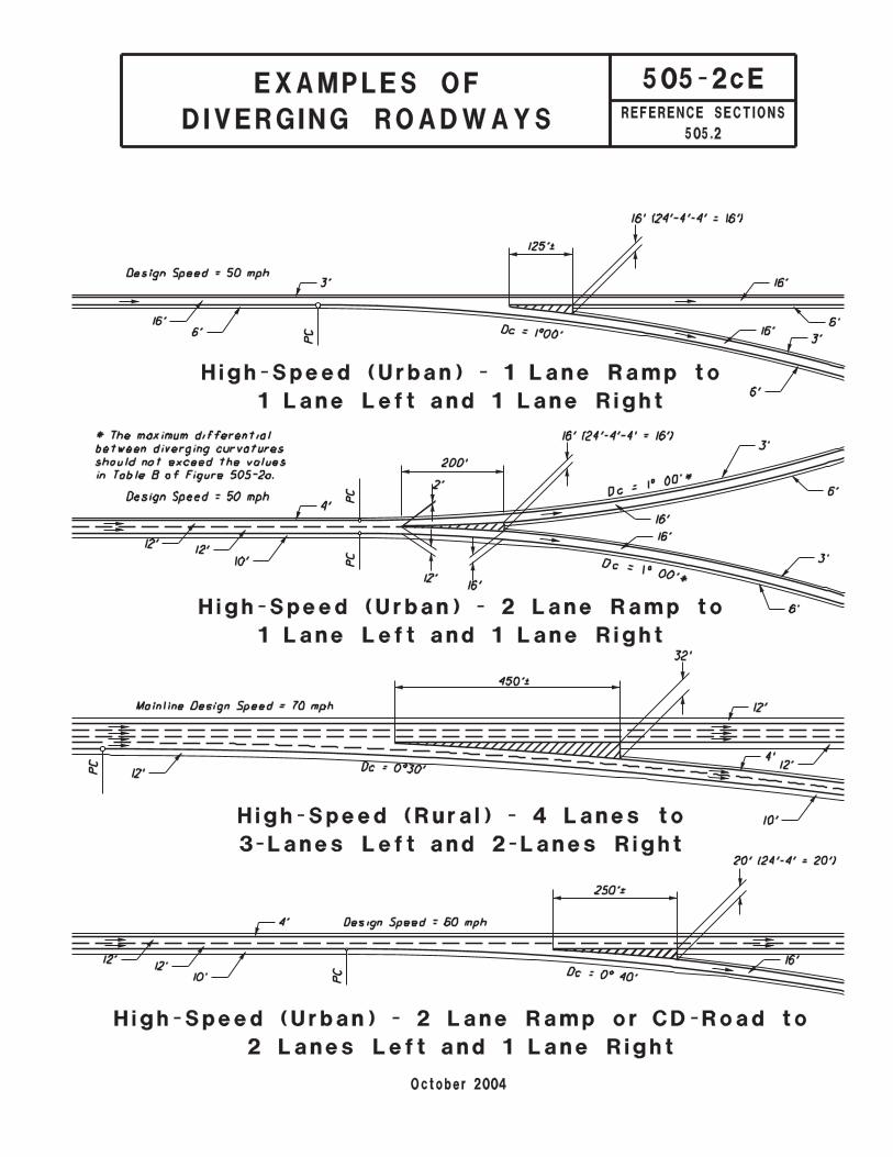
505.2.1 General Figure 505-2a shows the general design for multi-lane exit ramps and diverging roadways. A diverging roadway is defined as a single roadway which branches or forks into two separate roadways without the need of a speed change lane. Figure 505-2b shows the specific design to be used for two-lane High-Speed exit ramps. Figure 505-2c shows examples of designs for diverging roadways. High-Speed Diverging Roadways should be used when either or both the diverging roadways are mainline roadways of an expressway or freeway or at the divergence of high-speed directional ramps within an interchange. Low-Speed Diverging Roadways should be used at the divergence of low-speed directional ramps within an interchange or at the divergence of ramps with non-limited access roads or streets.
505.2.2 Lane Balance and Continuity In order to have lane continuity, the number of mainline lanes leaving the diverging nose must be equal to the number of mainline lanes approaching the nose. The total number of lanes leaving the diverging nose (mainline lanes plus diverging lanes) must be one greater than the total number of lanes approaching the nose to obtain lane balance. The purpose for obtaining lane continuity and lane balance is to avoid a drop lane situation. See Figures 505-2a and 505-2b.

500 Interchange Design
January 2018 5-13
It may be necessary to obtain this lane balance by adding additional lanes upstream from the diverging nose. The length of each additional lane should be 2,500 ft. and should be introduced using a 0 to 12 ft. taper with a length of 100 ft. as shown on Figure 505-2b for the approach roadway class and design speed. There may be conditions off the mainline, such as on Collector-Distributor Roads or within interchanges, where lane balance and continuity is less important. In such cases, the non-mainline roadway design on Figures 505-2a and 505-2b may be used.
505.2.3 Terminal Design The design of diverging roadway terminals is determined by the class and the design speed of the approach roadway, and is based on the neutral gore length "L" and the nose width "N" (See Figure 505-2a). Table A on Figure 505-2a lists length "L" and nose width "N" for various design speeds in diverging roadway classes. The "N" dimension should be exact, but the "L" dimensions may vary slightly from the Table A value.
505.2.4 Horizontal Curvature Table B on Figure 505-2a lists recommended values for the curve differential between the outer edges of traveled way of diverging roadways. These values apply only when the alignment between the diverging nose and the PC of the diverging curvature is on tangent or simple curvature. When compounded or spiral curvature is used in the diverging area, it will be necessary to design diverging roadway alignments individually to provide the proper "L" and "N" for the approach roadway Class and design speed.
505.2.5 Crest Vertical Curves When a diverging nose is located on a crest vertical curve, this vertical curve shall be designed using the design speed of the approach highway and decision stopping sight distance from Figure 201-6.
505.2.6 Superelevation and Joint Location The superelevation rate will be based on the design speed of the approach roadway. Reference should be made to Section 503.6.4 for other superelevation requirements. Longitudinal joints should be located so they will define the lane lines. Reference should be made to Standard Construction Drawing BP-6.1 for type and location. The joints in the gore area should be located to facilitate superelevation and pavement grading.
505.3 Four Lane Divided to Two Lane Transition Figure 505-3 shows a reversed curve design (Types A and B) a tapered design (Type C) and a design for a transition on a curve (Type D). The pavement transition should be located in an area where it can easily be seen. Intersections or drives should be avoided in the transition area. Vertical or horizontal curves should provide decision stopping sight distance. Reverse curve transitions should normally be used for median widths of 20 ft. or wider.

500 Interchange Design
January 2018 5-14
Taper lengths are calculated as shown in Section 401.6.1.
506 Service Roads
506.1 Use of Service Roads Service roads (frontage roads) are used to enhance capacity on the mainline, control access, serve adjacent properties, or maintain traffic circulation. They permit development of adjacent properties while preserving the through character of the mainline roadway. Service roads may be either one-way or two-way, depending on where they are located and the purpose they are intended to serve.
506.2 Design of Service Roads Although the alignment and profile of the mainline may have an influence, service roads are generally designed to meet the specific criteria based on functional classification (usually "local"), traffic volumes, terrain/locale and design speed. Two features, however, are unique to service roads and are further discussed below. They are (1) the separation between the service road and mainline and (2) the design of the crossroad connection. The further the service road is located from the mainline, the less influence the two facilities will have on each other. A separation width that exceeds the clear zone measurement for each roadway is desirable. However, the separation should be at least wide enough to provide normal shoulder widths on each facility plus accommodate surface drainage and a suitable physical traffic barrier. Glare screen is desirable to screen headlights when the service road is two-way. At crossroads, the distance between the mainline and service road becomes extremely critical. This distance should be great enough to provide adequate storage on the approaches to both the mainline and service road. The recommended minimum distance between the mainline and service road edges of traveled way is 150 ft. in urban areas and 300 ft. in rural areas. In addition, the designer should check the adequacy of stopping sight distance on the crossroad as well as intersection sight distance at the frontage road. Since service roads are normally maintained by local governmental agencies, the pavement design should either meet, or exceed, that required by the maintaining agency.
550 Requests for New or Revised Access - Interstate Highways or Other Freeways
550.1 General Control of access on the Interstate and other freeway systems is considered critical to providing the highest quality of service in terms of safety and mobility. This section provides guidance for the preparation and processing of access point requests in relation to new and existing interchanges on the

500 Interchange Design
January 2018 5-15
Interstate and other freeway systems in accordance to Federal Code 23 U.S.C. 111 and FHWA Policy – Access to the Interstate System (Federal Register: August 27, 2009, Volume 74, Number 165). The documentation required depends on the type of change requested - new or revised. New Access is the addition of a point of access where none previously existed. This includes the construction of an entirely new interchange such that it will result in additional points of access or additional ramps to existing interchanges. As an example, the reconstruction of an existing diamond interchange to a full cloverleaf interchange would add four new points of access. Revised Access is the major revision of an existing interchange such that the number of access points will remain the same but the operation and/or safety of the Interstate/freeway system may be affected. The changing of a cloverleaf interchange to a fully directional interchange, the conversion of a traditional diamond to a diverging diamond interchange, relocating an existing ramp terminal to a new roadway, and adding a collector-distributor system are all considered examples of revised points of access. New or revised access point requests require the preparation and processing of an Access Point Request Document. Generally, a new access requires an Interchange Justification Study (IJS), and a revised access requires an Interchange Modification Study (IMS).
550.2 Access Point Request Document The degree of complexity of the Access Point Request Document will vary depending on the character of the location (urban or rural) and/or whether the change involves a revised access point, a new access point at an existing interchange, or an entirely new interchange location. The following is a list of items which must be addressed in the justification study for a new or revised access on the Interstate/freeway system:
1. Adequate documentation that the existing access points and/or local roads are unable to handle the design year traffic demands while providing the access intended by the proposal, or be improved to do so, if the new or revised access is not provided. If the request involves a new access point, and particularly an interchange at a new location, a comprehensive description of the public need for the access must be included. A justification based on enhanced property values or access to private facilities will not be accepted.
2. Assurance that all reasonable alternatives for design options, location, and transportation system
management type improvements (such as ramp metering, mass transit, and HOV facilities) have been assessed and provided for if currently justified, or provisions are included for accommodating such facilities if a future need is identified.
3. Evidence that the proposed new or revised access does not have significant adverse impact on
the safety and operation of the Interstate/freeway system. The analysis must address design year traffic with and without the new or revised access point (build vs. no-build). Design year traffic must reflect future land use changes and associated trip generations. Traffic projections must be certified as per Section 102.1. In projects where complex changes in access are proposed a conceptual signing plan shall be included with the IMS.
Requests involving new access points or revised access points must use 20 year design traffic projected from the opening day of the interchange.
The level-of-service (LOS) of the Interstate/freeway system and the interchange components that are built new or modified should generally provide a LOS C, except certain cases in the MPO’s Boundary where LOS D may be acceptable (Refer to ODOT Policy No. 322-002(P), Policy for

500 Interchange Design
January 2018 5-16
Applying Level-of-Service and Volume-to-Capacity Ratio in the Transportation Development Process).
The proposed Interstate/freeway interchange or improvements cannot have a significant adverse impact on the safety and operation of the Interstate/freeway facility based on an analysis of design year traffic. Significant impact is defined as lowering the LOS one or more levels from the no-build condition, unless the resulting build LOS meets new design criteria specified in the previous paragraph. If the no-build LOS is F, or if the LOS is reduced, degradation is not assumed to occur unless the build traffic volume is greater than 2% more than the no build traffic volume in the peak hour of the design year using constrained traffic. If the traffic volume increase is greater than 2 percent, the project will not be permitted unless mitigative measures are included to either restrain vehicles from entering the freeway (i.e., ramp metering), or additional capacity is provided on the freeway to restore the LOS. ODOT and FHWA will decide what mitigative measures, if any, will be allowed.
The operational analysis shall, particularly in urban areas, include an analysis of sections of Interstate/freeway to and including at least the first adjacent existing or proposed upstream and downstream interchange. The analysis shall extend to at least where the no-build and build LOS are equal. Crossroads and other roads and streets shall be included in the analysis to the extent necessary to assure their ability to collect and distribute traffic to and from the interchange with new or revised access points. New interchanges must include analysis of the local street system to the extent that local road system improvements can be compared as an alternative to constructing a new interchange. Maps and/or diagrams should be provided as needed to clearly describe the location and study limits of the proposal.
For requests involving entirely new interchanges, the study should include a discussion of the distance to, and size of, communities to be served by the new interchange. An examination of proper interchange spacing must also be included.
4. Assurance that the new or revised access connects to a public road and is part of a configuration
that provides for all traffic movements. Less than “full interchanges” for special purpose access for transit vehicles, for HOV’s, or into park and ride lots may be considered on a case-by-case basis. Proposed design must meet or exceed current design standards.
5. The proposal considers and is consistent with local and regional land use and transportation
plans. Prior to final approval, all requests for new or revised access must be consistent with the metropolitan and/or statewide transportation plan, as appropriate, the applicable provisions of 23 CFR part 450 and the transportation conformity requirements of 40 CFR parts 51 and 93.
The request should include a statement and analysis of compatibility with, and the effect on, the local road network. Letters of support and commitment are required from the state and other sponsoring agencies for any required street or road improvements as well as for the access point.
6. In areas where the potential exists for future multiple interchange additions, all requests for new
or revised access are supported by a comprehensive Interstate/freeway network study with recommendations that address all proposed and desired access within the context of a long-term plan.
7. Evidence that the request for the new or revised access generated by new or expanded
development demonstrates appropriate coordination between the development and the necessary transportation improvements. A discussion of potential funding sources, if known, should be included.

500 Interchange Design
January 2018 5-17
8. The request for new or revised access contains information relative to the planning requirements and the status of the environmental processing of the proposal.
The Access Point Request Document should only be performed for the preferred alternative, however a discussion of feasible alternatives should also be included in the study. The preferred alternative will comply to all State and FHWA design requirements, including but not limited to: interchange spacing, interchanges to provide for all traffic movements to and from the freeway, not allowing lanes to drop into private facilities, not allowing intersections (driveways or streets) to intersect ramps (except in special cases such as facilities for utilities). A reevaluation of the IMS will be required if the project or a phase of the project has not been constructed within 8 years of the approval date of the document. In some cases, a Preliminary Access Point Request Document may be beneficial if it is suspected that a project would result in degradation to the freeway. The purpose of a Preliminary Access Point Request Document is to limit the risk of funding a IMS or IJS only to find that degradation would result to the Interstate/freeway and the project would not be approved. The preliminary document is simply an operational analysis using either preliminary or certified traffic to determine the effects on the Interstate/freeway mainline. There is no prescribed format for a preliminary study, nor is a preliminary study “approved” by any agency. It is simply a report to provide a comfort level of what impacts would be associated with an IJS or IMS. Preliminary Access Point Request Documents are particularly useful to determine mainline Interstate/freeway impacts of new interchanges. The development of an Access Point Request Document should be performed in accordance with the ODOT Project Development Process (PDP). However, care should be taken not to apply the PDP rigidly where Access Point Request Documents are concerned. Many projects are unique and demand flexibility in the application of the PDP. The phases in which work is done should be established during the project’s scope. Interchange Modification and Justification Studies (IMS & IJS) are required to reference and describe how each policy point in FHWA’s Policy on Access to the Interstate System is being met (link to latest policy: https://www/fhwa.dot.gov/design/interstate/170522.cfm). All IJS or IMS documents should follow the Report Format/Outline found in the Traffic Academy IJS & IMS Course Manual.
550.2.1 Interchange Operations Study (IOS) Many minor interchange projects, especially those involving service interchanges, do not fall under the definition of warranting an Access Point Request Document (IJS/IMS) per the Federal Policy on Access to the Interstate, but still require an operational evaluation and approval by the Office of Roadway Engineering. This operational evaluation would be in the form of a report referred to as the Interchange Operations Study, IOS. The IOS is intended to be an abbreviated version of the more comprehensive IMS report, highlighting critical traffic operations that may be affected by the proposed improvement. The IOS will utilize the same analysis methodology and 20 yr. design as the IMS, but the IOS will be more limited with respect to the number of analysis points evaluated and the study narrative. An IOS can be applied to an Interstate or non-Interstate. The following is a list of projects requiring an IOS:
1. Changing lane configurations at a ramp intersection approach, including: Adding a left, thru, or right turn lane along a crossroad Adding turn lanes to the exit ramp Changing lane assignments without altering the number of lanes
a. Example: Changing a 2 lane approach from a (Left/Thru-Right) to (Left-Thru/Right)
Implementing a Road Diet (reducing the number of lanes on the crossroad)

500 Interchange Design
January 2018 5-18
“Squaring” up a continuous right turn from the ramp/crossroad and regulating the movement with a signal
2. Changing the exit or entrance ramp terminus point with the freeway mainline by: Creating an optional exit lane Creating a 2-lane exit Creating a 2-lane entrance
3. Shifting a ramp’s location within the same interchange configuration 4. Changing traffic control type at a ramp/crossroad intersection:
Example: Revising from a signalized/unsignalized condition to a roundabout 5. Adding an auxiliary lane between 2 adjacent ramp interchange ramps
An IOS cannot be considered for: A) Major interchange design/revisions; B) New interchanges; or C) Interchange modifications necessitated by large developments or conditions that will significantly increase traffic volumes or revise traffic patterns. For all other interchange or mainline modifications that result in significant operational changes, not covered above or by an Interchange Modification Study, please contact the Office of Roadway Engineering.
550.2.2 Safety Improvements on Interstate or Other Freeways Safety improvements eligible for this process are defined as low to medium cost solutions that address an identified “spot” safety problem. The LOS provisions of 550.2 do not apply except that the LOS should not be degraded over the no-build condition in the design year. All other provisions of 550.2 still apply, including the IMS or IOS report to support the analyses. To determine degradation, the individual operational components shall be analyzed, but evaluated for acceptance within the context of the overall affected system. Though a single operational component could experience incremental degradation, the overall system should improve or essentially remain the same. For a safety improvement to qualify under this section, the following criteria must be met:
1. The project purpose and need is primarily to address “spot” safety problems. The purpose and need may not include operational performance or economic development objectives.
2. The location has separate independent utility from all other improvements 3. Any potential longer term solution which would provide LOS C would take 5 or more years to
implement. 4. No major rehabilitation or reconstruction is planned for 5 or more years. Other work (e.g.,
routine maintenance or minor rehabilitation) may be done within the 5 year window as long as it does not substantially replace the base pavement and/or reconfigure the facility.
5. The location is a spot location (defined as a ramp, intersection, merge/diverge point, weave, or mainline section not to exceed one mile).
6. The location planning level cost estimate is less than $5 million total (low to medium cost measures) for all phases of project development (i.e. preliminary engineering, detail design, right of way and construction).
550.3 Study Methodology
550.3.1 General One of the primary objectives of an Access Point Request Document is to determine if additional traffic enters the Interstate/freeway in the build versus the no-build case, and if traffic does increase, does it degrade the operation of the Interstate/freeway. In cases of new interchanges or new access points, the new roadway and connections will generally result in changed traffic patterns from the no-build case. In

500 Interchange Design
January 2018 5-19
the case of revised access projects, the build and no-build traffic volumes may be identical. In these cases, it is important to understand the concept of constrained traffic.
550.3.2 Constrained Traffic In many cases, the purpose of a project is to alleviate traffic congestion at an interchange, possibly due to over saturated ramp terminal intersections or inadequate ramp capacity. In these cases, the proposed solution generally includes capacity improvements such as turn lanes or additional through lanes intended to remove the geometric constraint, or “bottleneck”. In order to determine the real-world effect of the proposed improvement on the Interstate/freeway, traffic analysis tools such as the Highway Capacity Manual (HCM) or the Highway Capacity Software (HCS) must be used to find which movements entering the Interstate/freeway are over saturated in the no-build configuration. For over saturated movements, the demand volume should be divided by the volume-to-capacity (V/C) ratio of that movement to determine the actual, or constrained, flow volumes to be used in the downstream merge and mainline LOS calculations. The difference between the no-build constrained traffic flow and the build (typically unconstrained) traffic flow is the increase of traffic volume entering the Interstate/freeway. The No Build and Build ramp intersection analyses shall conform to the methodologies defined in Section 401.2 and Figure 401-14a. Refer to the Traffic Academy IJS & IMS Course Manual for a sample problem using the constrained traffic methodology.
550.3.3 Diagrams and Plans The Access Point Request Document should contain diagrams and plans as needed (as applicable) to indicate: project limits, adjacent interchanges, proposed interchange configuration, travel lanes and shoulder widths, ramps to be added, ramps to be removed, ramp radii, ramp grades, acceleration lane lengths, deceleration lane lengths, taper lengths, auxiliary lane lengths, and collector/distributor roads.
550.4 Environmental Studies Documentation of an initial overview or impact to the environment as a result of the access point or changes to an access point is required prior to initiation of the Access Point Request Document. The agency sponsoring the access request is required to perform all necessary project development and documentation, including environmental studies and identification of the Purpose and Need of the project, in accordance with ODOT and FHWA procedures as per the PDP. The environmental discussion to be included in the IMS is limited to a statement as to the current status of the environmental document and level of document (Categorical Exclusion, Environmental Assessment or Environmental Impact Statement).
550.5 Review Process All request submissions are to be sent to the Office of Roadway Engineering (one printed copy and one electronic copy, which may be available online) with two printed copies to the ODOT District Office. The Office of Roadway Engineering will be responsible for coordination with the Federal Highway Administration for studies involving Interstates. For Interstates, the Office of Roadway Engineering will review and approve the Access Point Request Document (IJS or IMS), and if acceptable, will forward the request to FHWA for their approval. If the environmental document has not been completed, approval will be conditional on acceptance of the environmental document. For Access Point Request Documents (IJS or IMS) involving non-Interstate freeways, the Office of Roadway Engineering will review the study and has approval authority.

500 Interchange Design
January 2018 5-20
For Interchange Operations Studies, the Office of Roadway Engineering will review and has approval authority. As a courtesy, all IOS submissions involving the Interstate will be made available electronically to FHWA. .

500 Interchange Design
January 2018
Figure Date Title 503-1E October ‘04 Ramp Design Speed Guide 503-1aE July ‘12 Minimum Ramp terminal Spacing 503-2aE October ‘04 Minimum Acceleration Lengths for High-Speed Entrance Terminals with
Flat Grades of 2% or Less 503-2bE October ‘04 High-Speed Entrance terminal Adjustment Factors as a Function of
Grade 503-2cE July ‘12 High-Speed Single-Lane Entrance Terminal 503-3aE October ‘04 Minimum Deceleration Lengths for High-Speed Exit Terminals with Flat
Grades of 2% or Less 503-3bE October ‘04 High-Speed Exit Terminal Adjustment Factors as a Function of Grade 503-3cE July ‘06 High-Speed Single-Lane Exit Terminal 503-4aE October ‘04 Low-Speed Entrance Terminals 503-4bE January ‘05 Low-Speed Exit Terminals July ‘12 Notes for Low-Speed Entrance and Exit Terminals 503-5E July ‘06 Uncurbed Ramp Intersection 503-5aE October ‘04 Transition From Single Lane to Two-Lane Exit Ramp 504-1E January ‘05 Collector-Distributor Entrance Terminals 504-2E October ‘04 Collector-Distributor Exit Terminals 505-1aE July ‘12 Multi-Lane Entrance Ramps and Converging Roadways 505-1bE October ‘10 High-Speed Two-Lane Entrance Terminals 505-2aE October ‘04 Multi-Lane Exit Ramps and Diverging Roadways 505-2bE October ‘04 High-Speed Two-Lane Exit Terminals 505-2cE October ‘04 Examples of Diverging Roadways 505-3E April ‘06 Transitions - Four Lane Divided Roadway to Two Lane Roadways

This page is intentionally blank


500 Interchange Design
July 2012
Notes for Low-Speed Entrance and Exit Terminals
Figures 503-4a and 503-4b
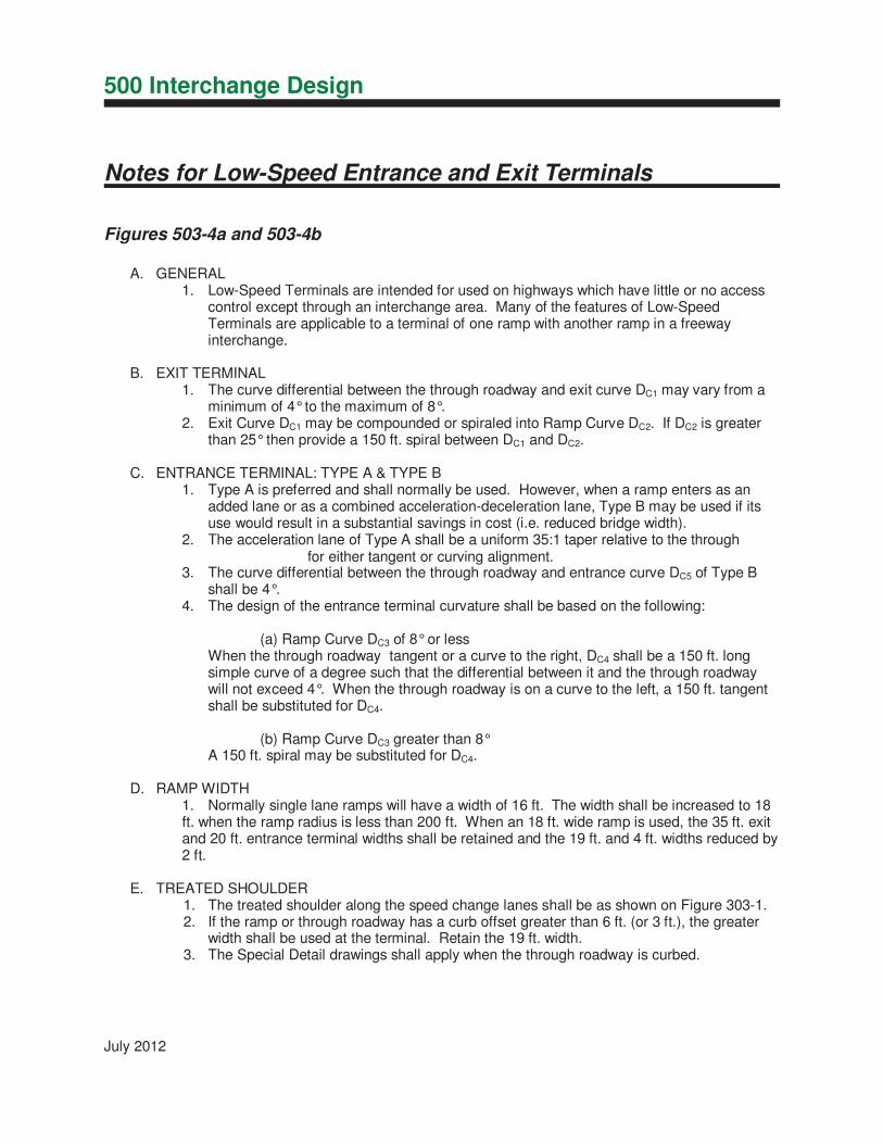
A. GENERAL 1. Low-Speed Terminals are intended for used on highways which have little or no access
control except through an interchange area. Many of the features of Low-Speed Terminals are applicable to a terminal of one ramp with another ramp in a freeway interchange.
B. EXIT TERMINAL 1. The curve differential between the through roadway and exit curve DC1 may vary from a
minimum of 4° to the maximum of 8°. 2. Exit Curve DC1 may be compounded or spiraled into Ramp Curve DC2. If DC2 is greater
than 25° then provide a 150 ft. spiral between DC1 and DC2.
C. ENTRANCE TERMINAL: TYPE A & TYPE B 1. Type A is preferred and shall normally be used. However, when a ramp enters as an
added lane or as a combined acceleration-deceleration lane, Type B may be used if its use would result in a substantial savings in cost (i.e. reduced bridge width).
2. The acceleration lane of Type A shall be a uniform 35:1 taper relative to the through for either tangent or curving alignment.
3. The curve differential between the through roadway and entrance curve DC5 of Type Bshall be 4°.
4. The design of the entrance terminal curvature shall be based on the following:
(a) Ramp Curve DC3 of 8° or less When the through roadway tangent or a curve to the right, DC4 shall be a 150 ft. long simple curve of a degree such that the differential between it and the through roadway will not exceed 4°. When the through roadway is on a curve to the left, a 150 ft. tangent shall be substituted for DC4.
(b) Ramp Curve DC3 greater than 8° A 150 ft. spiral may be substituted for DC4.
D. RAMP WIDTH 1. Normally single lane ramps will have a width of 16 ft. The width shall be increased to 18ft. when the ramp radius is less than 200 ft. When an 18 ft. wide ramp is used, the 35 ft. exit and 20 ft. entrance terminal widths shall be retained and the 19 ft. and 4 ft. widths reduced by 2 ft.
E. TREATED SHOULDER 1. The treated shoulder along the speed change lanes shall be as shown on Figure 303-1.2. If the ramp or through roadway has a curb offset greater than 6 ft. (or 3 ft.), the greater
width shall be used at the terminal. Retain the 19 ft. width.3. The Special Detail drawings shall apply when the through roadway is curbed.


REFERENCE SECTIONS
TW
O-
LA
NE
EXIT
TE
RMIN
AL
TW
O-
LA
NE
EXIT
TE
RMIN
AL
Diverging Nose Diverging Nose
PC
PC
Each additio
nal div
ergin
g road
way lane
must be developed as sho
wn
2500'
Mainlin
e
Desig
n Speed,
V
mph
Each additio
nal div
ergin
g road
way lane
must be developed as sho
wn
2500'
100'
Desig
n Speed,
V
mph
2500'
100'
100'
505.2
January 2015
EXIT TERMINALS
HIGH-SPEED TWO-LANE 505-2bE
EQ
UA
LS T
HE
NU
MB
ER
OF
AP
PR
OA
CH L
AN
ES
TH
E T
OT
AL
NU
MB
ER
OF L
AN
ES B
EY
ON
D T
HE
NO
SE
Thru Lanes
EQ
UA
LS T
HE
NU
MB
ER
OF
AP
PR
OA
CH L
AN
ES P
LU
S
ON
E
TH
E T
OT
AL
NU
MB
ER
OF L
AN
ES B
EY
ON
D T
HE
NO
SE
Thru Lanes
Fig
ure 505-2a
Table
A
L -
Gore Lenth
Fig
ure 505-2a
Table
A
N -
Nose
Width
Fig
ure 505-2a
See Table B
For
Div
ergin
g Curvature
Fig
ure 505-2a
Table
A
L -
Gore Lenth
Fig
ure 505-2a
Table
A
N -
Nose
Width
Fig
ure 505-2a
See Table B
For
Div
ergin
g Curvature


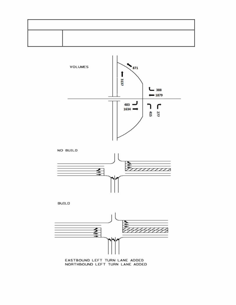
Calculation Sheet for Determination of Constrained Traffic Volumes Example
Example: Determine whether construction of additional turn lanes at a ramp intersection will degrade freeway operations. The proposed improvements consist of adding a secondary eastbound left turn lane on the arterial to the entrance ramp and adding a northbound left turn lane on the exit ramp. There is demand volume of 483 eastbound left turns, 388 westbound right turns, and 3,137 northbound through trips on the freeway mainline at the merge point. See diagram for traffic intersection layout and traffic volumes. The freeway is operating at LOS F in the no-build condition. (Note: An improvement is deemed to degrade the freeway operation if it increases traffic on freeway mainline by greater than 2.00% when the freeway is operating at LOS E or F in the No-Build condition.)
NO BUILD CONDITION Full demand eastbound left turn DHV onto freeway ramp = 483 vph v/c is 1.18 (from HCS analysis), > 1.0 so constrained Capacity Constrained volume = vph/(v/c) = 483/1.18 = 409 vph
Full demand westbound right turn DHV onto freeway ramp = 388 vph v/c is 0.61 (from HCS analysis), < 1.0 so not constrained
Total volume entering freeway ramp = constrained EBLT +WBRT = 409 + 388 = 797 vph
BUILD CONDITION Full demand eastbound left turn DHV onto freeway ramp = 483 vph v/c is 1.06 (from HCS analysis), > 1.0 so constrained Capacity Constrained volume = vph/(v/c) = 483/1.06 = 456 vph
Full demand westbound right turn DHV onto freeway ramp = 388 vph v/c is 0.51 (from HCS analysis), < 1.0 so not constrained
Total volume entering freeway ramp = constrained EBLT +WBRT = 456 + 388 = 844 vph
COMPARISON 844-797 = 47 additional vehicles entering the freeway with the proposed improvements.
% traffic added to freeway mainline due to improvements = additional vehicles entering freeway after improvements / (trips on mainline + No Build constrained vehicles entering from ramp)
47/(3137+797) = 1.19 % more traffic added to freeway due to improvement
1.19 % < 2.00 % Therefore, improvement does not degrade freeway operation

July 2012

July 2012