5. technicality of implementation of lump
TRANSCRIPT

5. Technicality of Implementation of LUMP
5.0 Introduction Implementation of LUMP requires land reclamation as per LUMP.
This requires suitable reclamation techniques. Further, implementability of the LUMP obviously depends upon its technical feasibility. Hence a provision has been kept in the suggested LUPg system for assessing technical feasibility of developing any suggested scenario through a specific reclamation activity.
In this reference it appears justified to detail some reclamation technologies to be used to mitigate the environmental impacts of mining on land and LU together with technical feasibility of these reclamation technologies.
Land reclamation in mining areas concerns mainly reclamation of quarries, solid waste dumps and subsided areas. The reclamation method to be followed depends upon the depth (& real extent) of the quarry, geology of the quarry site and the volume of OB/spoil available. Thus the matter has been discussed next following the different possible conditions.
5.1 Shallow pit without topsoil/solid waste There may be shallow pits without any (or much) of top soil or OB
or SP as in case of clay quarries or other shallow deposits. The best way to reclaim these is to backfill with suitable soil or soil substitutes, greenmulch, compost etc. and renewed for agriculture. Some abandoned pits resulting from exploitation of float ores in the neighbourhood of Mansar mine of MOIL have been refilled by OB and reclaimed by spreading topsoil stored earlier (Anon, 2000, pp.10).
5.2 Deep quarry without solid waste In case the quarry is deep without OB or any other form of solid
waste or SP or has not been back filled due to some cause or other, the most economic way to reclaim the quarry is to form a lake. These generally form perennial water bodies, as in most cases such OC mines behade aquifers. These hence form a perennial water source for the region around and helps compensating water scarcity due to mining, (if any such is caused). These can be dressed to generate fishery, swimming pool or any recreational facility to form an economic resource even (Nelson et al. 1982). In Indian condition quarries from limestone, manganese, dolomite iron ore etc. are best suitable for such reclamation.

Chapter 5
However, all quarries cannot be turned into lakes because that will cause huge number of water bodies disturbing the balance in the land-water-ecosystem in mining areas and will keep OB/SP-dumps unused, to be reclaimed separately. Hence, side by side, there should be an attempt to restore the original topography as far as possible, the final suggestion should however follow from LUMP.
5.3 Deep quarry with solid waste If it follows from LUPg that a big quarry is to be reclaimed by
backfilling, it is better to decide it at the premining stage itself; and the workplan should be chalked out to decide whether the quarry is to be backfilled by OB generated at the neighbourhood or by any other solid waste (SP). In such backfilling care should be taken on two points:
Filling should be made as compact as possible, using dumper or heavy earth moving machinery (HEMM) after each 2.5 to 3.5 meter, and finer compaction should be made by rollers, otherwise the openspace below the land generated by backfilling may disturb its usability. Even some layers of finer solid waste (if locally available) may be put in intermediate positions.
The newly developed land should match with surrounding topography, keeping in mind that such filling materials generally do not have soil or soil nutrient. These are to be covered by 25cm to 40cm of fertile soil or soil substitutes e.g. green mulch, organic compost etc. and then can be used for plantation of local hardy species. After long period of plantation the land will get compacted and come back to original condition.
Such backfilling will help using-up huge volume of OB and SP material also.
If it happens that the excavation takes out the total thickness of aquifer together with its base, simple backfilling cannot regenerate the impermeable base of the lost aquifer and the aquifer is lost for ever (Fig. 3.3). While the land generated by such backfilling is attempted for biological reclamation, i.e. to generate a sustainable greenery, common activity is to blanket the total land by topsoil (transported from somewhere else) or make pits of optimum size on the land and fill these with similar good soil, then greeneries are put on it.
Such activity grows greenery on the land with low survival rate because the abandoned quarry filled with OB material retains very high porosity and permeability (even if mechanically compacted), so that the topsoil put on it whenever receives any amount of water, the total soil together with water goes down rapidly upto the base of the backfilled

Technicality of implementation of LUMP
quarry, far beyond the reach of the saplings planted on the land. This results virtually to loss of topsoil. The saplings cannot get natural water from underground as the aquifer has already been excavated out.
Further, whatever greenery grows on such land, it grows at the cost of greenery growing potentiality of some other piece of land from which the topsoil was taken. The problem can be alleviated by regenerating some aquifer at optimum depth and searching out some substitute of topsoil. The procedure for these and hence the system to be followed for backfilling of such abandoned quarries has been detailed in Fig. 5.1 and in the flow chart Fig. 5.2 (Ghosh 2000c).
Information on rainfall becomes specially required if the quarry is not in sedimentary terrain or if the information on pre-mining water table/ aquifer can not be made available. With reference to the flow of activities required for the purpose (Fig. 5.2) to decide the position of the impermeable barrier to be formed, one has to know the depth (dm) and thickness Tm of the aquifer to be re-generated (or generated freshly).
The best means to decide this is by knowing the geology of the area. To plan any mining project it needs drilling in the region as a pre-requisite to confirm the deposit. Such bore-hole logs (or drill-cores if available) may be analysed thoroughly to know the depth and thickness of the aquifer lost or to be lost by excavation. The impermeable layer should be made at a calculated depth such that the lower boundary of the porous and permeable layer (made by the filling material) be in continuity of the base of the previous aquifer.
If due to some cause (stated above) or other, such information is not available, an alternative procedure of calculating the depth and thickness of aquifer to be constructed may be as detailed next: 1. Get information on average rainfall receipt
per yr. in the region : say, `X’ meter
(m). 2. Measure porosity of the solid waste to be
used for backfilling : say, a%.
3. Calculate the thickness of solid waste of a% porosity, required to hold `X’ m water
: say, `Y’ m.
4. The abandoned quarry should be first filled with any solid waste
: leaving `(Y+1)’ m unfilled.
5. The depth of aquifer base to be formed is : `(Y+1)’m. 6. The thickness of aquifer to be formed is : `Y’ m

Chapter 5
Fig. 5.2: Flow-chart of activities for aquifer (re) generation
Backfill the quarry by: SP/OB upto the base of aquifer planned
Make an impermeable layer by : clay/cement/polythene/ grouting or any as suits the situation
Cover it with grass mulch
Fill the depression with ob-material (a bit carefully not to damage the impermeable layer) upto 0.5m below the surrounding contour
Cover with grass weed-mulch
Put a layer of composted dairy/poultry/domestic/organic waste
Spray mixed seeds of suitable species
Cover with non grazable-weed-mulch
Level, doze & compact the backfilled quarry base
Based on above: decide the depth & thickness of aquifer to be formed
Get information on: (a) depth & thickness of pre-existing aquifer (b) amount of annual rainfall
Technicality of implementation of LUMP
5.4 Mining on slope In case of contour-strip mining artificial shelves are created on hill
slopes, these are to be reclaimed by planting local hardy species on benches. Such plantation should definitely merge with and add to the aesthetic value of the surroundings. A technique for growing greenery on such irregular stoney land is detailed next.
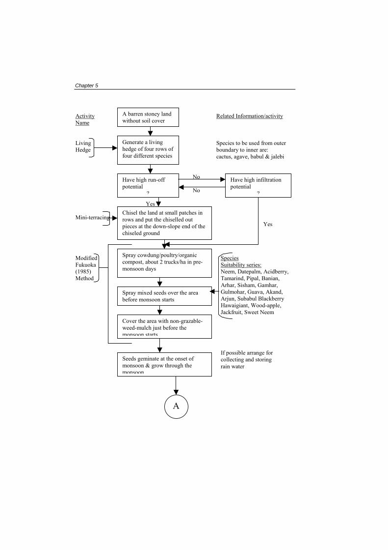
The chief requirements to make any plantation activity successful is soil, water and nutrients. The technique suggested for this has been generated through real-field case studies (Ghosh 1999a) on two extreme varieties of lands, one with high, deep infiltration and zero run-off while the other with high run-off, zero infiltration. Hence both the lands were having no water, no soil and no soil nutrient. Different sets of experiments were conducted for identifying the most suitable strategy on the following points for two extreme varieties of mining degraded lands mentioned above.
species suitability,
plot preparation technique
stages of sowing
process of sowing
after care
watering
Recommendations generated out of these experiments form a working model for soil rehabilitation/ regeneration which has been presented in the form of a flow chart of activities in Fig. 5.3 (Ghosh 1999a). The model is good for growing greenery on any barren land without requiring any topsoil.
While spreading of cowdung/ poultry/ organic compost has been suggested in the technique (Ghosh op.cit.1999), use of other waste products as listed in table 5.1 (c.f. Bradshaw & Chadwick 1980) and hydroseeding specifications as listed in table 5.2 (c.f. Bradshaw & Chadwick, op. cit) may also produce good results under certain conditions.
Chapter 5
Activity Related Information/activityName Living Species to be used from outer Hedge boundary to inner are: cactus, agave, babul & jalebi No No Mini-terracing Modified Fukuoka (1985) Method
Generate a living hedge of four rows of four different species
A barren stoney land without soil cover
Have high run-off potential
Yes
Sp Su Ne Ta Ar Gu Ar Ha
Jac
If p col rai
?
Chisel the land at small patches in rows and put the chiselled out pieces at the down-slope end of the chiseled ground
Spray cowdung/poultry/organic compost, about 2 trucks/ha in pre-monsoon days
Spray mixed seeds over the area before monsoon starts
A
Have high infiltration potential
Yes
ecies itability series:em, Datepalm, Acidberry, marind, Pipal, Banian, har, Sisham, Gamhar, lmohar, Guava, Akand, jun, Subabul Blackberry waigiant, Wood-apple, kfruit, Sweet Neem
?
Cover the area with non-grazable-weed-mulch just before the monsoon starts
ossible arrange for lecting and storing n water
Seeds geminate at the onset of monsoon & grow through the monsoon

Technicality of implementation of LUMP
Formation A depression may be arranged of mini- to collect community waste embankment water & thus generate an artifi- cial perennial water source Modified drip irrigation 2nd tier sowing
Fig.: 5 NB: If the situa
Agave andSeeds fromin next mgreening.
At the end of monsoon, dress the rotten weed-mulch to get depressions at the base of the saplings and elevations at the down-slope margin of the base land
A
As the plants show signs of water requirement, watering is to be done in early morning, only at the depressions made (as in previous step) to avoid run-off-evaporation-loss. Water from artificial perennial source to be used
Species Suitability series Arhar, self propagating Grass, castor, cowpea
.3: Flow of activities for greening stoney lands
tions do not permit following the total set of activities, only /or cactus may be grown in the whole plot in first monsoon. first part of species suitability series and/or grass to be tried onsoon. In the third monsoon the field will be ready for
At the beginning of next monsoon modified Fukuoka method to be repeated to green left over inter spaces
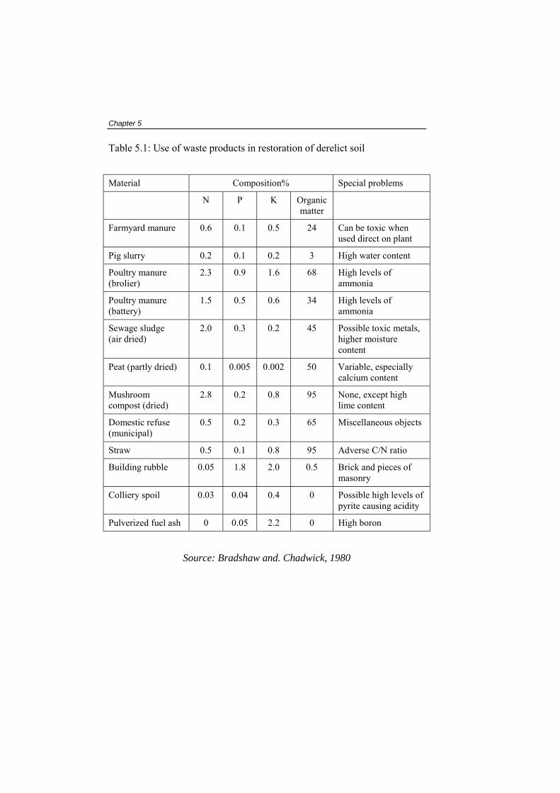
Chapter 5 Table 5.1: Use of waste products in restoration of derelict soil
Material Composition% Special problems
N P K Organic matter
Farmyard manure 0.6 0.1 0.5 24 Can be toxic when used direct on plant
Pig slurry 0.2 0.1 0.2 3 High water content
Poultry manure (brolier)
2.3 0.9 1.6 68 High levels of ammonia
Poultry manure (battery)
1.5 0.5 0.6 34 High levels of ammonia
Sewage sludge (air dried)
2.0 0.3 0.2 45 Possible toxic metals, higher moisture content
Peat (partly dried) 0.1 0.005 0.002 50 Variable, especially calcium content
Mushroom compost (dried)
2.8 0.2 0.8 95 None, except high lime content
Domestic refuse (municipal)
0.5 0.2 0.3 65 Miscellaneous objects
Straw 0.5 0.1 0.8 95 Adverse C/N ratio
Building rubble 0.05 1.8 2.0 0.5 Brick and pieces of masonry
Colliery spoil 0.03 0.04 0.4 0 Possible high levels of pyrite causing acidity
Pulverized fuel ash 0 0.05 2.2 0 High boron
Source: Bradshaw and. Chadwick, 1980

Technicality of implementation of LUMP
Table 5.2: Hydroseeding specifications for establishing grass/legume cover in temperate climates
Sl. No.
Material Rate of application
1. Mixture (appropriate) of grass-seeds (including nursecrop in exposed situations)
70 kg/ha
2. Wild white clover or other legume (innoculated and pre-germinated if necessary)
10 kg/ha
3. Mulch: woodfibre, chopped straw or glasswool
1-2 t/ha
4. Stablizer: woodfibre, alginate PVA or latex (if likelihood of severe erosion)
Depending on stablizer
5. Fertilizer: complete 15:15:15 (slow release N-fertilizer value if legume is not included)
200 kg/ha followed by 300 kg/ha after 8 weeks
or
Dry organic matter 500 kg/ha
6. Lime (if pH requires this and may have to be spread separately)
0-500 kg/ha
Source: Bradshaw and Chadwick, 1980
5.5 Soil management If the mineral to mine is deep-seated, covered by OB and topsoil,
preservation of this topsoil is very important. It is to be collected separately by scraping the top 10-150 cm layer (depending upon the soil profile) and stored properly to preserve its biolife and physical properties. In Indian condition (tropical climate) such scraped soil prove to be vulnerable to erosion, and if lost, create serious ecological damage by forming siltation on surrounding land and water and also creating loss of topsoil, a worthy natural resource; as nature takes several years to form 1 cm of topsoil.
Hence it will not be justified to loose the topsoil by getting mixed with subsoil or OB. Thus a calendar programme has been chalked out to reuse topsoil for its (most rapid use) on back-filled quarries even without

Chapter 5 requiring preservation through long time and has been named as “continuous and concurrent reclamation mining” (Ghosh & Ghosh, 1990a) as detailed below.
The model postulated here for reclamation in OC mining areas uses the “continuous reclamation mining method” outlined in Coates (1981, pp.600) as the base. Originally a somewhat similar method was used by EXXON Mining Corporation for surface mining without leaving significant scars on the land. A significant improvement in the proposed model over the earlier methods is the scope for special care to preserve and utilise the topsoil and subsoil separately and effectively. The method is good mainly for sedimentary deposits only.
As a first step, the total area for OC mining should be divided into more or less uniform plots of smaller size so that mining in each plot can be finished in 6 months. The exact size of the plot should depend on the mechanisation and labour force available. Actual operation should start with corner plot, i.e. plot 1, which should be excavated first only to take out and dump the topsoil and subsoil separately in the fringe area of this plot. Preservation of these dumps should be such that these are not washed away within one year. For this, any available natural depression (not holding an usable water source) should be preferred as dumping ground. Suitable embankments may be constructed to prevent rain washing. A comparatively easy method, involving minimum expenses for preservation of sub-soil is to put on the dump the cut-out twings and leafy parts of the plants and other types of greeneries to form a mulch. In fact site preparation would require cutting out some amount of greeneries which can be used for such purposes. Grasses with their roots and 6″ of soil (in the form of soddings) can be used to cover the topsoil dump to obtain a special care for preserving biolife of the soil. The grasses will survive very easily and will form a temporary cover on the soil heaps and protect it from being washed away by rain waters. The leaves will protect the soil at their base until they are dried, rotten and decomposed. The roots of grass and cut-out plants will act as soil binder until these are decomposed. After decomposition these will add nutrients to the underlying soil. Even some of the roots may grow to give rise to some natural vegetation and protect soil from erosion (Haigh, 1976). Thus according to this plan, the soil along with its fertility will be preserved for one year at a minimal cost in terms of labour only.
The next step would involve excavation of OB from plot 1. The OB is to be dumped separately at a properly selected site and preserved by planting rapidly growing grass and shrubs on the dump so that the dump is preserved for a longer time. Studies about slopes of lands disturbed by

Technicality of implementation of LUMP
surface mines suggest that the slopes covered by a dense seeded turf have about a third of soil loss than the unvegetated parts (Haigh, 1976).
Then comes the actual exploitation of the mineral and its transportation. Towards the last phase of extraction of mineral from plot 1, site preparation should begin in the neighbouring plot2. This starts with removal of vegetation and its temporary dumping over the topsoil and sub-soil heaps from plot 1. This is followed by removal of topsoil and sub-soil from plot 2, to be covered immediately by the freshly heaped vegetation mulches over the topsoil and subsoil heap from plot 1. By this time mining operation should be completed in plot 1.
The removal of OB from plot 2 starts, which should be put in the exploited pit of plot 1. Then as the excavation starts in plot 2, another group of labour should put back first the sub-soil and then the topsoil dump of plot 1, along with the decomposed plant tissues in the filled in (by OB) quarry of plot 1.
Every stage would require mechanical compaction. Two groups of labours in necessary strength should be deployed in a calculated manner, so that this cycle of four stages is completed within one year, before the topsoil and sub-soil looses its nutrients and fertility and hence capacity to grow fresh vegetation.
Repetition of this sequential plan in successively adjacent plots, one after another, should be done to cover the entire area. Finally, the OB dump of plot 1 should be used to fillup the quarry in the last plot. Hence it was mentioned that due care should be taken to select the dumping site for OB from plot 1, and its preservation. An operation plan for this model is presented in Fig. 5.4.
This method has three specific advantages: Each plot is receiving its topsoil and sub-soil back to its
original position before one year, i.e. before its biolife and nutrients are lost. It is expected that in most cases the land will grow at least grass on it naturally (as in grazing fields) leading to a natural soil conservation. It may be worth mentioning here that according to Haigh (1977) spreading a vegetation cover is the best method to check the rate of accelerated soil erosion on the surfaces disturbed by mining activities. Aforestation or plantation or cultivation may be taken up later, if so required. These areas will now be covered by relatively loose soil containing composted mulches and therefore will be suitable for cultivation, which will gradually lead to compaction.

Chapter 5
By this method only two plots of land are getting damaged in a single phase of time, while the rest of the area will remain usable, at least for agricultural purpose.
The method requires only planned activity and soil rehandling but not much of extra cost to achieve greening of the area.
The natural vegetation and compaction thus obtained should be followed by cultivation. This type of vegetation in two phases is practiced in outer Himalayas (Shastry et al., 1981). Regarding species selection, Kilmartin & Haigh (1988) has indicated that, the first priority is to clothe the ground with some kind of vegetation. Moreover, it is easier to construct a stable self-sustaining ecosystem by using local natural biological resources. The best solution may be to use species which are naturally colonizing in the sites around.
For cases where this system cannot be applied, an alternative to “continuous and concurrent reclamation mining” is “growing greenery without topsoil” as detailed in section 5.4 through Fig. 5.3.
5.6 Solid waste management
5.6.1 Management strategy The solid waste in case of OC mining is generally OB, or tailings or
by-products of mineral processing (SP).
The best way of solid waste management is to use-it-up. That part of solid waste not used in quarry backfilling forms a dump, occupies some land and disturbs the surrounding land also which has already been discussed.
The use of dump material depends on its quality (physical & chemical characteristics). If the dump is composed of igneous or metamorphic or any very hard and compact rock, its crushing strength bearing strength etc. should be tested in the laboratory for its suitability as construction material/road metal etc. and may be used suitably. The softer ones, i.e. those coming out from sedimentary deposits should be better used for backfilling the quarries. Such materials can also be used for stabilising slopes by forming "ripraps" (Coates 1981). 5.6.2 Dump management
Volume of solid waste, which cannot be used-up by any means may be allowed to form "waste dumps".
The location to form the waste dump should be decided through LUMP. Its topsoil should be scrapped first to use

Technicality of implementation of LUMP
somewhere else or to store for future use. During site selection for forming such waste dumps, the regions LU, topography hydrogeology etc. should be thoroughly studied. The importance and procedure of such activity has been detailed in a model study made on JCF (Ghosh & Ghosh 1990b).
The final shape of waste dump should be such that the surfaces are stable. The out slopes should not exceed 20° from the horizontal.
Long slopes allow high surface runoff and hence high erosion, so the slope surfaces should be short lengthed so that the vertical fall in individual terrace donot exceed 10m.
Drainage lines (grassed water ways) should be constructed to prevent runoff on slope and gully erosion.
Any gully, if forms even after above care, should be plugged at different places on the slope (across the length of the gully) at a distance of 1 to 2 m such that base of upper barrier is slightly below the top of the next barrier downslope (section 5.7.5).
The dumps should be bounded by toe-barriers around the base. These should be low height walls with sloping walls outside so that the base is wider than the top with openings at selected sites so that the water can be collected at suitable sites, treated and allowed to flow through planned avenue and not to create any land degradation.
The basic clue of "waste management" is "waste recycling". This is true for "waste space" or "waste dump" even. As a quarry (space) can be best managed by using it for any purpose, similar is the case of a waste dump, when it acts as a "resource". An old example very relevant at this point is the early mining of iron ore in the Adirondack mountains, where the old tailing dumps of ilmenite were rewarked as a resource for Ti and the dump was being used up (as detailed in section 3.3.2).
The basis of LUMP follows from the above. Any piece of land holding some unusable solid, liquid or condition (chemical or physical) needs altering that unusable one to usable state. The exact activity required will be case specific, as the situations may vary between wide ranges, some of which have already been discussed.
5.7 Water resource management Importance of water resource management in LU has been
emphasised by Lee e. al., (1991) and Chandra (1992). The matter has been detailed next to a considerable extent.
Chapter 5 5.7.1 Management strategies
Biological regeneration of an area is required in many cases for implementation of the suggested LUMP. Mining activities are bound to damage water resource in the area in one way or other. Water resource and LUP in any area are complementary to each other. To develop any suggested LUP optimum quality and quantity of water resource is very much required. Similarly proper, well planned LUP is a tool to achieve optimum water resource.
In the background of this basic concept the table 5.3 has been generated to summarise the impacts of mining on water regime and possible mitigation strategies. However water balance study and water balancing is of prime importance in all such activities.
5.7.2 Water balance study Classical System: Water balance of an area, is defined classically by a hydrologic equation given below, which is based on the assumption that in a specified period of time all water entering in a given area must be consumed, stored or allowed to go out as surface or sub-surface flow (Garg, 1993)
P + Wi = R + Et + Wo ± <Sg ± <Ss …..............(1)
Where P = precipitation, Wi = surface and groundwater imported from areas outside the
region, R = stream out-flow, Et = evapotranspiration,
Wo = groundwater out-flow,
<Sg = change in groundwater storage, and
<Ss = change in soil moisture storage.
The parameters in equation (1) are defined next so as to understand these for practical purposes.
Technicality of implementation of LUMP
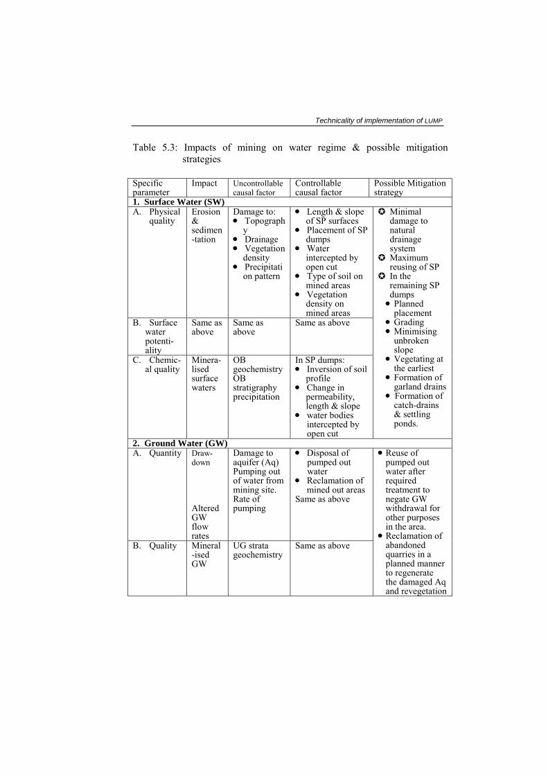
Table 5.3: Impacts of mining on water regime & possible mitigation strategies
Specific parameter
Impact Uncontrollable causal factor
Controllable causal factor
Possible Mitigation strategy
1. Surface Water (SW) A. Physical
quality
Erosion & sedimen-tation
Damage to: • Topograph
y • Drainage • Vegetation
density • Precipitati
on pattern
• Length & slope of SP surfaces
• Placement of SP dumps
• Water intercepted by open cut
• Type of soil on mined areas
• Vegetation density on mined areas
B. Surface water potenti-ality
Same as above
Same as above
Same as above
C. Chemic-al quality
Minera-lised surface waters
OB geochemistry OB stratigraphy precipitation
In SP dumps: • Inversion of soil
profile • Change in
permeability, length & slope
• water bodies intercepted by open cut
Minimal damage to natural drainage system
Maximum reusing of SP
In the remaining SP dumps
• Planned placement
• Grading • Minimising
unbroken slope
• Vegetating at the earliest
• Formation of garland drains
• Formation of catch-drains & settling ponds.
2. Ground Water (GW) A. Quantity Draw-
down Altered GW flow rates
Damage to aquifer (Aq) Pumping out of water from mining site. Rate of pumping
• Disposal of pumped out water
• Reclamation of mined out areas
Same as above
B. Quality Mineral-ised GW
UG strata geochemistry
Same as above
• Reuse of pumped out water after required treatment to negate GW withdrawal for other purposes in the area.
• Reclamation of abandoned quarries in a planned manner to regenerate the damaged Aq and revegetation
Chapter 5 Precipitation (P) – The total water received through hailstorm, snowfall,
rainfall, etc. over the area. Imported water (Wi) - Surface water flowing in the streams, and ground
water inflow in the area. Stream outflow (R) - The quantity of water outflowing through streams
from the area. Evapotranspiration (Et) - The quantity of water lost through evaporation
from the ground surface and transpiration through the leaves of the plants.
Groundwater outflow (Wo) - Ground water flowing out of the area.
Change in groundwater storage (<Sg) - The change in the volume of saturated thickness of the aquifer.
Change in soil moisture storage (<Ss) - The change in moisture content in top-soil and sub-soil. This is generally taken as negligible for larger time periods.
The Presently Suggested System: The above water balance equation does not take into account the water quality factor, and the requirement of water for various human purposes. For the water balance study, which takes into account all the requirements and environmental considerations the following equation can be used.
Requirement of water (quality and quantity-wise) for all the purposes in the area
↔ Availability of water (quality and quantity wise) from all the sources in the area
If the requirement is more than the availability, the area is deficient in water and on the other hand if the availability of water is more than the requirement the area is surplus in water. Further, if in a region it is seen that a specific quality water is falling short while some other quality water is available more than its requirement, it may be enquired whether this extra water may be treated to upgrade its quality to meet the shortage of better quality water. This treatment may be techno-economically more feasible than meeting the shortage by water transportation. Hence the availability should be assessed and arranged in terms of both quality and quantity. Using this concept the exercise for balancing can be done in the manner described later.

Technicality of implementation of LUMP
As is evident, it is necessary to identify all the water sources and then to assess the availability of water from them both in terms of quality as well as quantity. Similarly, it is also necessary to assess the requirement of water for purposes both quantitatively as well as qualitatively.
A very important point, though understood, worthy mentioning here is, any water balance study should be made for a complete watershed or a mini- or micro-watershed and definitely not for a country, state or district.
Identification of Water sources: The water sources in any area can be classified into the following two categories.
1. Surface water sources
2. Sub-surface and underground water sources
The `Surface Water Sources' include the followings.
Rainfall.
Rivers and their tributaries.
Water storages in the form of lakes, ponds, tanks, etc.
The `Sub-surface and Underground Water sources' include the followings.
Aquifers, both confined and unconfined.
Water being pumped out of the workings below land surface of the mines in mining areas (if it is used through recycling).
Availability of Water: In most area, specially in those having monsoon type climate or seasonal or occasional rainfall, the total quantity of water available from the various sources varies. It is expected to be more in rainy seasons/months and less in dry seasons/months. Therefore, to assess the availability of water from the sources it is necessary to establish an `availability pattern' for each source separately.
The availability pattern can be established on the basis of month-wise water availability data. The data for about 10-years should be taken into consideration to establish this pattern, which then can be used to anticipate the availability of water for future.
In the Indian context it will not be possible to get the water availability data except rainfall for 10-year period and the exercise of water availability assessment may have to depend on the data for one year only.
Month-wise average availability of water can be computed by the available standard methodologies, some of which are briefly given next.

Chapter 5
1. Rivers and their tributaries - The quantity of water flowing through the rivers can be computed by knowing the cross-section of river bed, the height of water level and the rate of flow. In fact for a definite cross-section of a given site the height of river stage can be a direct measure of the water quantity flowing through the stream by using suitably calibrated stage-discharge-relation curve (Hammer & Mackichan, 1981).
2. Mine water - The quantity of water being pumped out of the mines can be computed by knowing the rate of pumping and the time for which pumping is being done. This water comes out from confined and unconfined aquifer as the case may be. It forms a water source only if it is re-used. But if it is thrown off the area (as run-off or evaporation) it is rather to be substracted to calculate the actual water availability.
Similarly water discharged from any place of water use, should be analysed and studied how it can be treated and recycled so that forms a source, otherwise if it is allowed to flow away uselessly it creates a series of additional problems, like pollution of land and water resources etc.
To assess the suitability of water for various uses it is necessary to determine the quality of water available from each source and then compare it with the suitability criteria. If the quality of water available does not conform to the suitability criteria, necessary arrangements may have to be made for treatment of water to achieve the desired quality.
Quality Criteria: Permissible limits for the pollutants for various uses of water and effluent discharges have been defined by the Bureau of Indian Standards (BIS) under IS 10500 for drinking water, IS2490 for effluent discharges on inland surface and water for different purposes, and IS2296 for sewerage discharge.
By analysing the water from the various sources to assess the contaminants present and comparing the extent of contamination with the various water quality standards, the quality of water available from the sources can be defined. However, there may be seasonal variation of water quality, which can be ascertained by assessing the quality in all the seasons.
Water Inventory: With the information on quality and quantity of water from various sources available, an inventory can be drawn in respect of water availability.
Water Availability Forecast: The data on water availability in the past can be used to forecast its availability in future by trend analysis. Since the past

Technicality of implementation of LUMP
data may not be available in most cases in Indian scenario it may not be possible to do the trend analysis. The forecast in such cases may have to be made on the basis of the available data and the data generated during the water balance study.
It may be mentioned here that the water holding capacity of the surface storages, unconfined and confined aquifers may reduce with time. In case of surface storages, the capacity decreases due to silting; while in case of groundwater, recharge decreases due to compaction of the soils, and the aquifers' capacity decreases due to its compaction as a result of ground water withdrawal.
Water Requirement: In any inland area water is required for various purposes, e.g., domestic, agriculture, horticulture, industries, recreation poultry, dairy etc.
Requirements are to be calculated for the present time, after 5 years, 10 years and 15 years; calculation is to be based on the following.
Requirements of population: including ethnic, other supporting services and even floating population, e.g. those coming at the time of sowing, harvesting, etc. As per Indian standard, requirement is 50 gpd per head as against the international standards of 100 gpd and even more.
Requirements for irrigation/watering: Water is required for agriculture (for crops), horticulture (for fruits & vegetables) and pisciculture (for fisheries). Land-use information will give the area for each variety, while crop pattern will give the requirement of water/unit area. Further irrigation requirement depends upon climatic factors e.g. evaporation potential and quantity and distribution of rainfall in "time".
While considering the long time requirement, expected land-use changes are also to be taken care of considering the fact that population-pressure and mining activities effect other land-uses, e.g. agricultural/forest land is converted to settlement area.
Requirements for industries: Water requirement for industries is to be calculated considering input, output and discharge quantity and quality. Thermal power stations require water for energy generation. Central Pollution Control Board (CPCB) specifications are to be considered (as per IS 2490).
Recreational requirement: This is to be calculated considering quantity as well as quality.
The water quality and quantity required for various purposes can be assessed by having an inventory of the planned activities and water
Chapter 5 requirement for them. Depending upon the nature of the activity there may be variation in the requirement of water quantity and quality.
The requirement for domestic consumption: This may not vary much round the year, while for agriculture it will be seasonal and will depend upon the crop pattern and rainfall pattern. In case of the industries the requirement will depend on the nature of the activities in the industries and recycling provisions.
In case of water requirement if the data is available from the past, a trend analysis can be done for forecast of water requirement on the basis of the present level of activities. However, in forecasting the water requirement, both in terms of quality and quantity, for any area the activities planned for future should be taken into account.
With the help of the data it should be possible to assess and forecast the qualitative and quantitative requirement of water for various purposes in any given area.
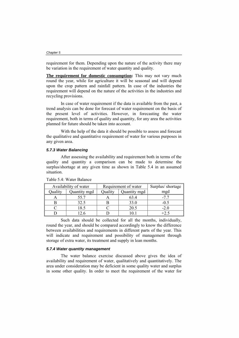
5.7.3 Water Balancing After assessing the availability and requirement both in terms of the
quality and quantity a comparison can be made to determine the surplus/shortage at any given time as shown in Table 5.4 in an assumed situation.
Table 5.4: Water Balance Availability of water Requirement of water
Quality Quantity mgd Quality Quantity mgd Surplus/ shortage
mgd A 55.7 A 63.4 -7.7 B 32.5 B 33.0 -0.5 C 18.5 C 20.5 -2.0 D 12.6 D 10.1 +2.5
Such data should be collected for all the months, individually, round the year, and should be compared accordingly to know the difference between availabilities and requirements in different parts of the year. This will indicate and requirement and possibility of management through storage of extra water, its treatment and supply in lean months.
5.7.4 Water quantity management The water balance exercise discussed above gives the idea of
availability and requirement of water, qualitatively and quantitatively. The area under consideration may be deficient in some quality water and surplus in some other quality. In order to meet the requirement of the water for

Technicality of implementation of LUMP
various purposes not only for the present but also for future it is necessary to look into management measures. Some of the measures are discussed hereunder. From the water quality which stands extra, if the surplus amount can be treated to meet the deficiency of some other quality and the treatment cost is economic, it may serve the purpose.
In some situations there may be locational difference in the availability and requirement, i.e., the required quality and quantity of water is available at some distance from the place of requirement. In such cases suitable water transportation arrangements are to be made, e.g., through canals, pipe line transport, etc. It would be advisible to compare such transportation cost with the cost of treatment of water of other quality in required quantity to required quality, if available nearby.
If the water is to be brought from outside the area, it would be necessary to locate the sources of water and the quality of water available therein and then examine the various options for transporting and treating the water so as to make it available at the place of requirement economically.
As mentioned in Table 5.3 reclamation of abandoned quarries may be achieved by different processes generated through different research activities. Mention may be made of aquifer regeneration (Ghosh 2000a&c), revegetation (Ghosh & Ghosh 1993, Ghosh et al., 1993, Singh & Ghosh, 1996, and Ghosh, 1999a), formation of surface water storages (Ghosh and Ghosh 1994) as some of the best ways of water resource management.
Augmentation of water quantity in mining complexes can be done by taking the following actions.
By producing green cover on mined out areas at the earliest (Ghosh 1999a).
By storing water in underground openings in the abandoned underground mines (Saxena, 1999).
By regenerating aquifers while backfilling the opencast mining areas (Ghosh 2000c).
By forming surface water storages in reclaimed opencast mining areas (Nelson et al., 1982).
Reactivating water table in subsided areas by suitably plugging the cracks.
Rain water harvesting (Vishwanath, 2001).
Optimum development of water resources can be achieved by the conjunctive use of surface and ground waters. Ground water recharge

Chapter 5 occurs in nature by seepage from canals and reservoirs and return flow from irrigation. It can be augmented by artificial methods such as spreading of pumped out mine water or storm water in ponds or basins Fig.5.5a, recharge pits recharge Fig. 5.5b, wells Fig. 5.5c and shafts. Even pumped-out mine-water may be poured (after due consideration of its quality) in goaves (Saxena, 1999) at proper distance (not to generate more pumping-requirement at the excavation site) or, may be poured in abandoned quarries to form a surface water storage or may be used for other purposes on the surface to curtail pumping requirements for those purposes (Fig.5.6) (Ghosh & Ghosh 1994). Nelson et al. (1982, pp.1.3-3) have proposed mine-cut lakes and has mentioned that such lakes may be of equal or better economic or public use as compared to pre-mining land-use. The usable capacity of the ground water reservoir can be developed by planned extraction of ground water during periods of low precipitation while subsequent replenishment can be made during periods of surplus surface supply. Such a coordinated operation of surface and ground water supplies is possible if there is sufficient ground water storage to meet the requirements for regulation of local and imported water supplies and if the aquifers possess sufficient transmissibility to permit the movement of recharged water to the area of extraction. Also, the underground storage is free of losses due to evaporation etc. The lesser danger of destruction of ground water reservoir structures and wide dispersion of outlet facilities in earthquake areas, in places liable for atomic attacks, etc. make ground water basins of inestimable value as an emergency supply. Large ground water reservoirs thus developed not only meet the deficiencies of the surface supplies in seasons of drought but also supplement these to a large extent. These conjunctive operations result in a more economic yield as they provide more water at a lower average cost. The benefits accruing from the conjunctive use of water sources are being listed below.
1. Formation of a large-subsurface storage at a relatively lower cost and safe against any risk of dam failures or pollution.
2. Provides water supplies during a series of drought years while a surface storage can at the most tide over one such year.
3. Provides efficient water use from well-spaced wells due to smaller surface distribution system than a canal irrigation scheme.
4. Water table can be controlled by pumping from wells and prevent water logging in canal-irrigated areas. This can reduce land subsidence due to reduced ground water levels particularly in confined aquifers.

Technicality of implementation of LUMP
5.7.5 Water quality control As discussed earlier water in mining complexes is polluted due to
various activities and to meet the water requirement for various purposes it is necessary to supply the desired quality of water. Hence, water quality control in the mining complexes is important.
In the mining complexes water is available from various sources including the water being pumped out of the mines. In order to plan and undertake the water quality control measures it is necessary to know the quality of water that is being pumped out of the mines and the charcterisistics of the effluents.
Depending upon the characteristics of the pumped water, waste waters and the effluents and the quality requirement, the water pollution control and management strategies are planned. The various methodologies that can be used in water and effluent treatment are as listed hereunder (Ghosh, et al.,2002).
1. Control of suspended solids • Mechanical separation • Centrifuges • Cyclones • Screening • Filtering • Thickening • Inclined plate settlers • Flocculation • Floatation
Floto-flocculation• Settling ponds •
tro f dissolved solids 2. Con l o• Neutralisation • Adsorption • Ion-exchange • Reverse-osmosis
3. Con l o etc.
The var s to be addressed in water management in mining
• Freezing tro f bacteria, • Disinfection iou issues that are
complexes are as discussed hereunder.
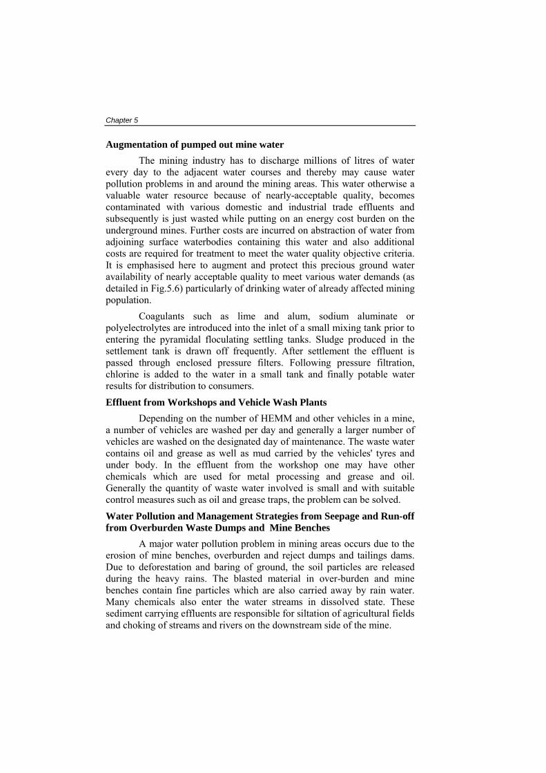
Chapter 5 Augmentation of pumped out mine water
The mining industry has to discharge millions of litres of water every d
ulants such as lime and alum, sodium aluminate or polyelec
le Wash Plants ehicles in a mine,
a numb
ff
urs due to the erosion
ay to the adjacent water courses and thereby may cause water pollution problems in and around the mining areas. This water otherwise a valuable water resource because of nearly-acceptable quality, becomes contaminated with various domestic and industrial trade effluents and subsequently is just wasted while putting on an energy cost burden on the underground mines. Further costs are incurred on abstraction of water from adjoining surface waterbodies containing this water and also additional costs are required for treatment to meet the water quality objective criteria. It is emphasised here to augment and protect this precious ground water availability of nearly acceptable quality to meet various water demands (as detailed in Fig.5.6) particularly of drinking water of already affected mining population.
Coagtrolytes are introduced into the inlet of a small mixing tank prior to
entering the pyramidal floculating settling tanks. Sludge produced in the settlement tank is drawn off frequently. After settlement the effluent is passed through enclosed pressure filters. Following pressure filtration, chlorine is added to the water in a small tank and finally potable water results for distribution to consumers. Effluent from Workshops and Vehic
Depending on the number of HEMM and other ver of vehicles are washed per day and generally a larger number of
vehicles are washed on the designated day of maintenance. The waste water contains oil and grease as well as mud carried by the vehicles' tyres and under body. In the effluent from the workshop one may have other chemicals which are used for metal processing and grease and oil. Generally the quantity of waste water involved is small and with suitable control measures such as oil and grease traps, the problem can be solved. Water Pollution and Management Strategies from Seepage and Run-ofrom Overburden Waste Dumps and Mine Benches
A major water pollution problem in mining areas occof mine benches, overburden and reject dumps and tailings dams.
Due to deforestation and baring of ground, the soil particles are released during the heavy rains. The blasted material in over-burden and mine benches contain fine particles which are also carried away by rain water. Many chemicals also enter the water streams in dissolved state. These sediment carrying effluents are responsible for siltation of agricultural fields and choking of streams and rivers on the downstream side of the mine.

Technicality of implementation of LUMP
Mining areas in general fall under monsoonal influence with relatively heavy seasonal rainfall with a natural propensity for high erosion and run-
el is to collect all the run-off water from higher
at the top of channel - 50 cm to 60 cm
s laid across the slop f water in these while it
rains are used to
mber of rills leads
d to be provided (length of
off rates. In the overburden dumps, a low angle of slope should be adopted with terracing and bamboo barricades in the slopes, stone barriers at the toe of dumps, check-dams in the channels and gully plugging. These measures apart from considerably reducing run-off also prevent mechanical damage to plants already existing and raised, save agricultural fields and adjoining river water courses from pollution. Some of the measures are briefly described below.
1. Catch-Drains and Diversion Channels: As the very name implies, the function of such a channlocations and prevent it from running down a vulnerable slope. These are to be laid across the slope on the uphill side before the commencement of a vulnerable slope. Suggested (Changmai, 1999) dimensions of such a channel are :
Width at the bottom of channel - 20 cm to 30 cm
Width
Depth of channel - 30 cm to 45 cm
While carrying such water through diversion channele, it is very much necessary to minimise velocity o comes from highland to lowland. Thus diversion channels should
be connected by grassed/vegetated waterways along the prevailing slope. The greeneries hinder the run-off for a while, also arrest the solid particles which were being carried by it and hence work as "catch-drains".
Such diversion ditches are useful even in guiding the water to main sumps from the mine benches. In underground mines, garland d
reduce water inflow through subsidence cracks.
2. Gully Plugging: Formation of rills or micro-channels is inevitable in the slopes in the existing conditions, and convergence of a nuto the formation of a gully. Such gully should be treated by providing suitable plugs filling up the width of the gully from the highest location downwards. A plug generally consists of two rows of driven-in stout branch-cuttings (or species that sprout readily) “Agave” is specially good for gully plugging. The suggested (Changmani, op.cit.) spacing between two row being about 60 cm to 1m. The gap between the rows is to be filled up by prostrate rows of brush-wood. (Fig.5.7a).
In case it is required to form a masonary/stone plug, on the down-stream side of the plug, a boulder-lined apron nee

Chapter 5 apron b
ses which carry the run-off materials from the
ocated 6 to 10m away from the base of the
ided to sedimentation ponds for settlement of suspended solids
eing about twice the height of plug) (Fig. 5.7b). The interval between successive plugs should be such that the top of the down-stream plug is at the same level as the bottom of the adjacent plug on the upstream side. To be really effective, the entire length of a gully may be covered by such barriers or plugs.
3. Check Dams or Spoil Dams: These barriers are to be set across channels or water-couroverburden dumps and are intended for holding up such run-off materials and preventing transportation/deposition of those in downstream areas. It is suggested (Changmai, 1999) in order to be effective, in each channel there should be series of such check-dams, erected along the width of the channel (to extend and protrude into the firm banks on either side), starting from the commencement of the channel. Each successive dam in a channel should be located in such a way, that a line, joining the bottom (ground level) of the upstream dam and the top of the next down-stream one, should not have a gradient in excess of 1 in 500. On the downstream side of each dam, there should be an apron of 50 cm deep layer of boulders engaged in wire-netting, covering the entire width of the channel. The length of apron (along the length of the channel) should be twice the height of the related check dam. The check-dams are to be built up of boulders (at least 30 cm diam), laid over a wirenetting at the bottom and the same wire netting raised along the sides also, so as to enclose the entire mass of boulders making up the dam. There should be no earth or sand input to fill up the voids in the boulders. The height of the first dam at the highest upstream location will vary according to the height of the banks and those of the subsequent dams on downstream locations will be governed by the thumb-rule indicated earlier in this para. The wires of the wire-netting used in these constructions should be of at least 8-gauge category.
4. Toe Barriers: These barriers, made up of dry stone masonry, are erected parallel to the toe of the dumps, ltoe. These barriers are not designed to serve the purpose of retaining walls for which a much more massive and costly structure will be required. The barriers are intended for containing the finer particles of run-off from spreading onto adjacent areas. For a stone-wall having a height of 2.5m, it is stipulated that the width of the foundation should at least be 4m, the width at the base should be at least 3m, and the slope of the wall on the outer or down-hill side should be flatter (1 in 1) to provide a proper batter (Ghosh et al., 2002).
5. Sedimentation Ponds: All surface run-off water containing sediments should be gubefore discharge of water into natural streams. Provision of such
Technicality of implementation of LUMP
sedimentation ponds have recently been made in a number of mining areas. However, the cleaning and maintenance of these ponds is required to be done on periodic basis. Technique for calculating the size of such ponds and the required detention time of run-off in it can be worked out by following the calculations of Brune (1953), Segarra & Loganathan (1992) and Loganathan et al. (1994) respectively. These have been further used by Raghunath (1985) and Mays (1996).
Installation of oil and grease traps to prevent the discharge of effluents from vehicle wash and workshop is required though quantity of effluent
m for
e of all efforts it
s generated is comparatively small in volume. Then the treated effluents can be combined with sewerage system for final treatment.
6. Artificial Rim For Controlling Run-off From Stockpile: Mined out materials should be stacked on prepared floor with an artificial ricollecting run off to prevent uncontrolled discharge of polluted water from the stockpile. The artificial rim can be made of waste rock in which case it works as a filter and also permits guiding of the run-off water to the central pool from where it can be sent to the sedimentation pond.
7. Collecting and Recycling of Seepage Water From Tailings Dams: This topic has been detailed in Ghosh et al., (2002). Inspitis sometimes not possible to make tailings dams completely seepage free. The common way to control water pollution from such seepage is to prepare a small toe dam on the downstream side and collect the seepage water which can be pumped back to the main reservoir. In this manner zero discharge can be achieved from the slurry pond. While all efforts should be made to reduce and control water pollution in mining areas it must be remembered that hydrologic disturbance is created in another way, namely, reducing availability of water in the aquifer and surface streams on the downstream side of the mining project. The quantity of water used for spraying purposes in crusher houses, and for spraying on haul road etc. is almost wholly lost to the atmosphere by evaporation and only a small proportion goes as run-off to the mine sump. Mining can also destroy the recharge area in many cases, or through deforestation reduce the infiltration ratio and increase the run-off. This is another cause of reduction in the water availability for the community because of the mining project. All efforts should, therefore, be made to reduce the industrial water consumption in mining. The use of wetting agents and road dust control chemicals instead of spraying water should be practised and the process water from mills and washeries should be reused. At the final stage of an opencast mine, it should be the national policy to create a water body of about 30m depth which would be a community asset in providing irrigation water and recharge of ground water in the region.