4wd_jm
TRANSCRIPT

4WD SYSTEM (ITM: Interactive Torque Management)
Chonan Technical Service Training Center 1
Electronically Controlled
On-Demand 4WD System

4WD SYSTEM (ITM: Interactive Torque Management)
Chonan Technical Service Training Center 2
CONTENTS
1. INTRODUCTION ----------------------------------------------------------------------
2. T/M & TRANSFER CASE ---------------------------------------------------
3. COUPLING & REAR AXLE ASSEMBLY ---------------------------------------
4. INPUTS AND OUTPUTS -------------------------------------------------------------
5. DIAGNOSIS ------------------------------------------------------------------------------
6. WIRING DIAGRAM ---------------------------------------------------------------------
7. 4WD COUPLING ASSEMBLY -------------------------------------------------------
4WD SYSTEM (ITM: Interactive Torque Management)
Chonan Technical Service Training Center 3
1. INTRODUCTION
Controllability of the vehicle in all driving situations is becoming an important promotional factor for
All-Wheel-Drive. An AWD vehicle has better road handling and is safer in all driving situations.
Answering these requirements, the new Electronically Controlled On-Demand 4WD of JM offers
fully controllable torque transfer characteristics and extremely rapid activation and deactivation
automatically. SANTA FE equipped Diesel VGT (Variable Geometric Turbocharger) engine has
been already using this system since November 2002. However most parts of the system such
as T/M case, transfer case, front differential and rear differential cannot be interchangeable
between JM and SANTA FE.
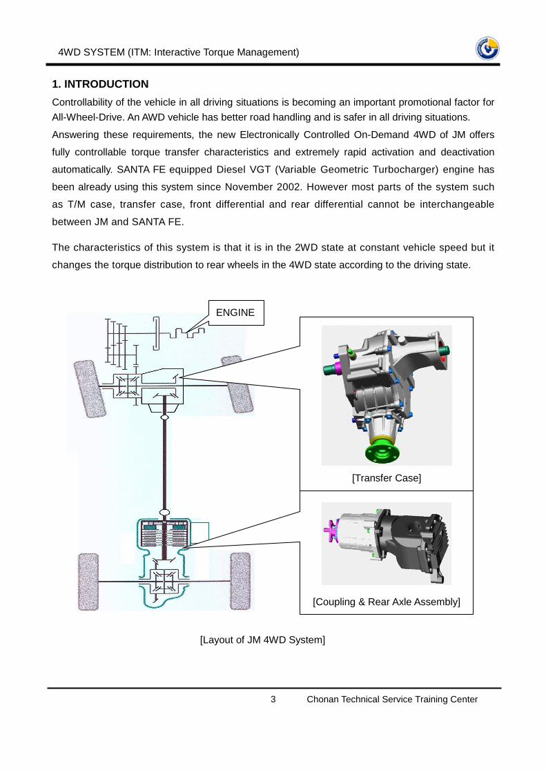
The characteristics of this system is that it is in the 2WD state at constant vehicle speed but it
changes the torque distribution to rear wheels in the 4WD state according to the driving state.
ENGINE
[Transfer Case]
[Coupling & Rear Axle Assembly]
[Layout of JM 4WD System]

4WD SYSTEM (ITM: Interactive Torque Management)
Chonan Technical Service Training Center 4
1.1 APPLICATION
REGION
LINE-UP
M/T
A/T
M/T
A/T
д-2.7V6
A/T
AUSEC
SO
-
-
O
- O
GENERALAREA
O -OO
O
O
в-2.0CVVT
- O
MIDDLEEAST
KOREANORTH
AMERICA
DDC 2.0DSL
O -O
OOO
- O OOO
O
O
O
O
* O: Optional Item, S; Standard Item
1.2 ADVANTAGES
Maximum performance and safety are achieved in all driving situations, as shown here:
Enhanced Vehicle Traction
- Torque transfer up to 1,200 Nm
- Full function in reverse
- Instant activation on differential speed
Enhanced Vehicle Dynamics
- Improved dynamics during acceleration and deceleration
- Rapid activation and deactivation
- Fully controllable torque transfer characteristics
Enhanced Vehicle System Compatibility
- On-line communication with the CAN system
Enhanced Vehicle Driving Comfort and Transparency
- No wind-up during tight cornering and parking
- Optimal traction during acceleration
Enhanced Optimization of Weight and Fuel Consumption
- The fully controllable torque transfer characteristic decreases the design requirements of the
complete AWD drive line, resulting in reduced weight and reduced fuel consumption

4WD SYSTEM (ITM: Interactive Torque Management)
Chonan Technical Service Training Center 5
Variable Torque Control
- At Parking: Low or zero torque transfer needed for easy and comfortable maneuverability
- Acceleration: High torque transfer for maximum traction on all four wheels
- High speed driving: Reduced torque transfer, to minimum, still adding dynamic stability
- Driving on slippery/wet roads:
Swift activation of the coupling for maximum traction and safety depending on the slip of the
wheels. The coupling is in on-line communication with other safety systems in the vehicle
- Braking/ABS: Immediate deactivation on ABS signal to ensure full function of ABS system
- ESP/TCS
Immediate deactivation on ESP/TCS signal to ensure full function of ESP/TCS system.
Alternative is to communicate with the ESP/TCS system for adding the control possibility of the
new ON-Demand 4WD System to the ESP/TCS System
- Off-road: Rapid activation with high torque transfer for maximum traction

4WD SYSTEM (ITM: Interactive Torque Management)
Chonan Technical Service Training Center 6
2. T/M & TRANSFER CASE
- 4WD Transfer Case: Santa Fe base modification
- T/M Case: Modification of 4WD transfer matching part
- T/M Differential for 4WD: Modification of transfer matching part

4WD SYSTEM (ITM: Interactive Torque Management)
Chonan Technical Service Training Center 7
3. COUPLING & REAR AXLE ASSEMBLY
- Coupling: Same as Santa Fe
- Rear Axle: Santa Fe base modification
- Control Unit: Santa Fe base modification (Location: under the driver seat)
3.1 SPECIFICATION (ITM: Interactive Torque Management)
FeatureSelf-contained, compact, light-weight, torquetransfer device for on-demand 4WD
Torque 2000 Nm
Weight 8 kg
Size 150mm Long, 140mm OD, 120mm ID
Housing Aluminum
Operating Voltage 12 volts
Operating Temperature -40 Ў Й ~ 150 Ў Й
4WD Coupling Oil Mobil Fluid – LT (0.15L)
Primary Clutch Disc (3 EA), Plate (3 EA)
Secondary Clutch Disc (10 EA), Plate (10 EA)
ITM
4WD SYSTEM (ITM: Interactive Torque Management)
Chonan Technical Service Training Center 8
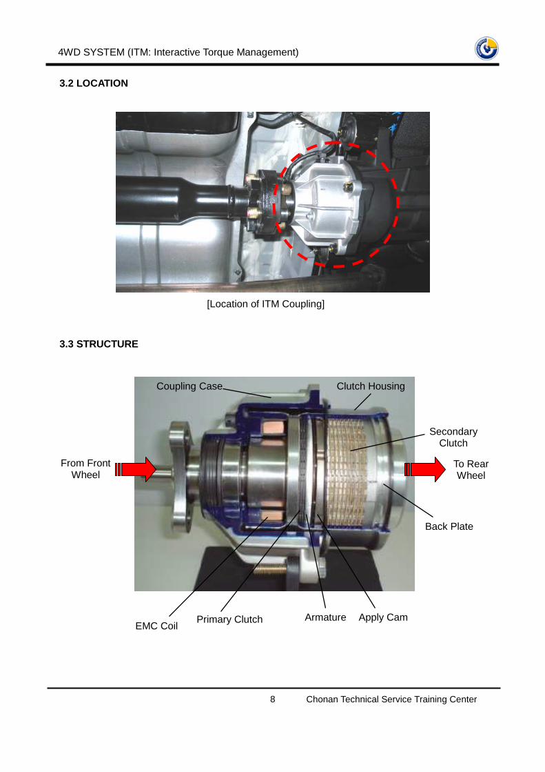
3.2 LOCATION
3.3 STRUCTURE
[Location of ITM Coupling]
EMC Coil Primary Clutch Apply Cam
Secondary Clutch
Back Plate
Armature
Clutch Housing Coupling Case
From Front Wheel
To Rear Wheel

4WD SYSTEM (ITM: Interactive Torque Management)
Chonan Technical Service Training Center 9
3.4 COMPONENTS
Wave spring
Snap ring
Oil seal
Snap ring
Back plate Snap ring
Thrust race
Thrust washer
Base cam
Steel balls (6EA)
Disc
(10EA)
Plate
(10EA)
Disc
(3EA) Plate
(3EA)
Armature
Input shaft Nut
Spacer Oil seal
Flange
Oil seal
Snap ring
Coupling case
Electric magnetic clutch
Clutch housing
Primary clutch
Secondary clutch
214-218 (2140-2180, 158-161)
TORQUE : N⋅⋅⋅⋅m (kg⋅⋅⋅⋅cm, lb⋅⋅⋅⋅ft)

4WD SYSTEM (ITM: Interactive Torque Management)
Chonan Technical Service Training Center 10
4WD ECU
[Housing] Primary Clutch [Primary Clutch]
Armature Base Cam [Base Cam]
[Armature]
Apply Cam Balls
Back Plate To rear differential EMC connector

4WD SYSTEM (ITM: Interactive Torque Management)
Chonan Technical Service Training Center 11
3.5 OPERATION OF COUPLING
- Constant speed drive: almost 2WD state
- Torque distribution (4WD state) changes according to the driving state (ex: sudden start,
turning, at low-mu surface) by the ECU logic
- Basic information: Input torque (Throttle Position Sensor), Steering Angle Sensor, Wheel
Speed Sensor, Brake Signal as well as ABS signal
- EMC Coil energizes to operate the Primary Clutch
- The amount of electromagnetic force in the Primary Clutch decides displacement of a Base
Cam
- Displacement of the Base Cam increases frictional force between Inner Plates and Outer
Plates of the Secondary Clutch
- While braking: performs a different control logic to get efficient braking
·Throttle Position Sensor
·Wheel Speed Sensor
·Steering Angle Sensor
·ABS Signal
4WD ECU
Torque distributed at the
4WD coupling
Judge the driving
state
Decide an optimal
torque distribution
4WD operation
[Operating Chart]

4WD SYSTEM (ITM: Interactive Torque Management)
Chonan Technical Service Training Center 12
1) MODULATING PRIMARY CLUTCH
Ошибка!
When an EMC Coil energizes, electromagnetic field is generated attracting an Armature as well as
Primary Clutch and it increase the frictional force between inner metal plates and outer metal
plates of Primary Clutch.
Higher frictional force applies bigger torque to rotate the Base Cam because the outer plates
splined to a clutch housing and the inner plates splined to a Base Cam..
PRIMARY CLUTCH
CLUTCH HOUSING
ARMATURE
Compress Primary Clutch
Primary torque in base cam
Input torque from propeller shaft
Magnetic Field
EMC COIL
Modulating Primary Clutch
Apply Force Multiplier
Secondary Wet Friction Clutch

4WD SYSTEM (ITM: Interactive Torque Management)
Chonan Technical Service Training Center 13
2) APPLY FORCE AMPLIFIER
When the primary torque in the Base Cam increases, the Base Cam begins to rotates over the Ball
on the Apply Cam and it pushes the Apply Cam increasing the apply force to the Secondary Clutch.
3) SECONDARY WET FRICTION CLUTCH
The apply force from the Apply Cam compresses the Secondary Clutch and it increases the
frictional force between inner plates which is splined with a Input Shaft and outer plates which is
splined to a Clutch Housing. The more frictional force generates the higher output torque.
Back Plate
Clutch Plates
Apply Cam
Compress
Secondary Clutch
Clutch Housing
Output torque to Rear Axle
Apply Force
Primary torque in base cam
Ball
Apply Cam
Base Cam
Ball cam at rest
Primary torque in base cam

4WD SYSTEM (ITM: Interactive Torque Management)
Chonan Technical Service Training Center 14
4. INPUTS AND OUTPUTS
* CAN (Controller Area Network)
4WD
CONTROL
MODULE
(ITMCM)
BATTERY & IGNITION1
STEERING ANGLE SENSOR (ESP by CAN)
WHEEL SPEED SENSOR (ABS/TCS, ESP by CAN)
ABS ACTIVE (by CAN)
4WD LOCK SWITCH
TPS (by CAN)
EMC
4WD WARNING LAMP
DIAGNOSIS
INPUTS OUTPUTS
4WD LOCK LAMP

4WD SYSTEM (ITM: Interactive Torque Management)
Chonan Technical Service Training Center 15
1) STEERING ANGLE SENSOR (Refer to ESP section for detailed information)
Steering angle signals of the vehicle with ESP (Electronic Stability
Program) come to the ITMCM through the CAN BUS line. However
without ESP, steering angle signals directly come to the ITMCM from the
sensor side. With the steering angle information, the ITMCM detects the
amount of steering and it controls the EMC coil current to prevent torque
conflict between the front wheels and the rear wheels.
2) WHEEL SPEED SENSOR (Refer to ESP section for detailed information)
Wheel speed sensor signals of the vehicle with ABS/TCS, ESP come to
the ITMCM through the CAN BUS line. However vehicle with a
conventional brake system, wheel speed signals directly come to the
ITMCM from the sensor side. 4WD system always comes with ABS/TCS,
ESP or conventional brake system not with ABS only.
ITMCM varies the EMC current by the Information of the speed
difference between the front wheels and the rear wheels.
For example, if the speed difference is high, more EMC current is applied by the ITMCM to
reduce the speed gap.
� Front wheel speed = (FL Wheel Speed + FR Wheel Speed) / 2
� Rear wheel speed = (RL Wheel Speed + RR Wheel Speed) / 2
3) ABS ACTIVE SIGNAL
Vehicle is in ABS control, ITMCM does not control the EMC current. Vehicle condition is in 2WD
state.
4) TPS
ABSCM
17
10㏀
IGN
ITMCM
(NO ABS CONTROL �� 9.0V, ABS IN CONTROL �� 0.5V)
- Type : ABSCM side --- OPEN COLLECTOR TYPE
- ITMCM side --- 12V PULL UP
- PULL UP resistance = 10§ �
4WD SYSTEM (ITM: Interactive Torque Management)
Chonan Technical Service Training Center 16
TPS information comes from the ECM through the CAN BUS line. TPS is an input torque data.
TPS angle suddenly increases, then the applied current to an EMC goes up. Therefore the
torque distribution to rear wheels goes up.
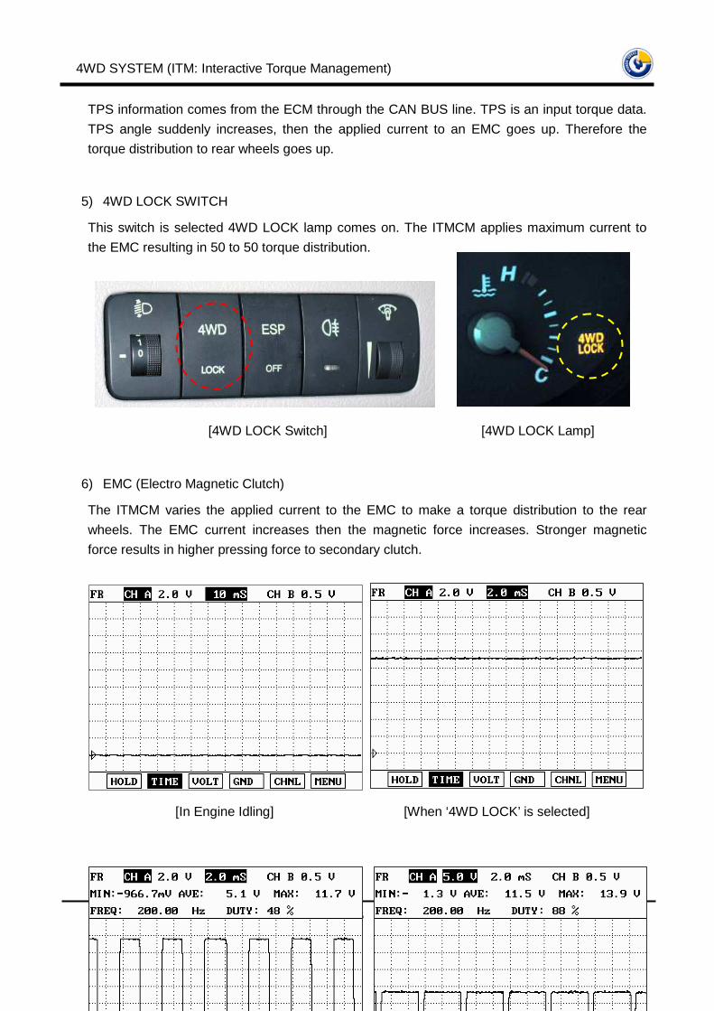
5) 4WD LOCK SWITCH
This switch is selected 4WD LOCK lamp comes on. The ITMCM applies maximum current to
the EMC resulting in 50 to 50 torque distribution.
6) EMC (Electro Magnetic Clutch)
The ITMCM varies the applied current to the EMC to make a torque distribution to the rear
wheels. The EMC current increases then the magnetic force increases. Stronger magnetic
force results in higher pressing force to secondary clutch.
[4WD LOCK Switch] [4WD LOCK Lamp]
[In Engine Idling] [When ‘4WD LOCK’ is selected]

4WD SYSTEM (ITM: Interactive Torque Management)
Chonan Technical Service Training Center 17
7) 4WD WARNING LAMP
4WD warning lamp blinks (2Hz) when a system failure is detected.
5. DIAGNOSIS

4WD SYSTEM (ITM: Interactive Torque Management)
Chonan Technical Service Training Center 18
While the ITMCM is actived it periodically monitors its inputs
and outputs. If a fault is detected the Diagnostic Bulb is
illuminated and flash at a rate of 0.25 seconds “ON”, and 0.25
seconds “OFF”. A fault code will also be stored in the ECU
memory.
The first time a fault is detected a DTC is stored in the ECU’s
Non-Volatile memory. This DTC will remain in memory until
the ITMCM is instructed to erase DTC's by the diagnostic tester.
DTC's will not be erased by disconnecting power to the ITMCM.
DTCs ITMES DESCRIPTION
P1717 Steer 1 Loss of signal out of range
P1718 Steer 2 Loss of signal out of range
P1719 Steer C Loss of signal out of range
P1726 TPS input-loss of signal Loss of signal out of range
P1728 EMC-open/short to battery Short/Open to battery
P1729 EMC-short to ground Short to ground
P1750 FLSS loss of signal Malfunction of front & left speed sensor
P1751 FRSS loss of signal Malfunction of front & right speed sensor
P1752 RLSS loss of signal Malfunction of rear & left speed sensor
P1753 RRSS loss of signal Malfunction of rear & right speed sensor
P1764 ECM-ITM CAN line, or ECM side
malfunction Malfunction of ECM-ITMCM CAN line
P1765 TCS-ITM CAN line, or ECM side
malfunction Malfunction of TCSCM-ITMCM CAN line
Input Error
Description Diagnostic
Diagnostic Lamp
Clearing Strategy
[ITM Control Module]
4WD SYSTEM (ITM: Interactive Torque Management)
Chonan Technical Service Training Center 19
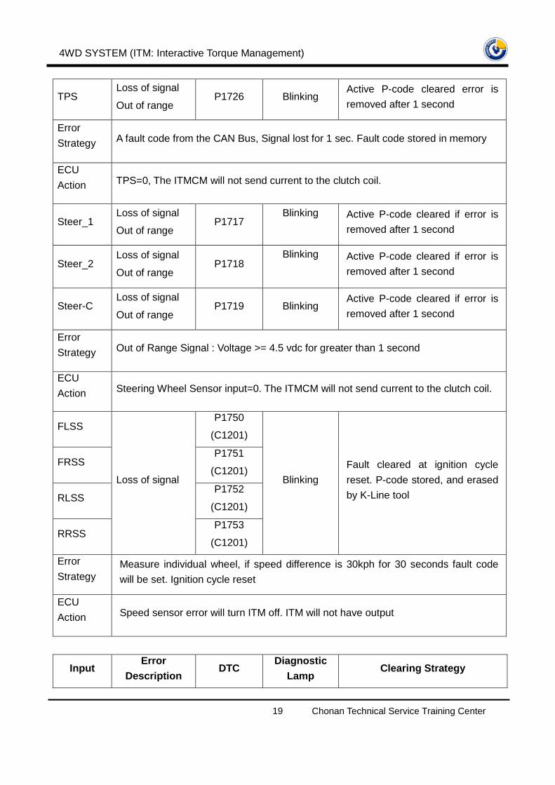
TPS Loss of signal
Out of range P1726 Blinking
Active P-code cleared error is
removed after 1 second
Error
Strategy A fault code from the CAN Bus, Signal lost for 1 sec. Fault code stored in memory
ECU
Action TPS=0, The ITMCM will not send current to the clutch coil.
Steer_1 Loss of signal
Out of range P1717
Blinking Active P-code cleared if error is
removed after 1 second
Steer_2 Loss of signal
Out of range P1718
Blinking Active P-code cleared if error is
removed after 1 second
Steer-C Loss of signal
Out of range P1719 Blinking
Active P-code cleared if error is
removed after 1 second
Error
Strategy Out of Range Signal : Voltage >= 4.5 vdc for greater than 1 second
ECU
Action Steering Wheel Sensor input=0. The ITMCM will not send current to the clutch coil.
FLSS P1750
(C1201)
FRSS P1751
(C1201)
RLSS P1752
(C1201)
RRSS
Loss of signal
P1753
(C1201)
Blinking
Fault cleared at ignition cycle
reset. P-code stored, and erased
by K-Line tool
Error
Strategy Measure individual wheel, if speed difference is 30kph for 30 seconds fault code
will be set. Ignition cycle reset
ECU
Action Speed sensor error will turn ITM off. ITM will not have output
Input Error
Description DTC
Diagnostic Lamp
Clearing Strategy

4WD SYSTEM (ITM: Interactive Torque Management)
Chonan Technical Service Training Center 20
C.A.N
ECM-ITMCM
Communication
Line, or ECM
side malfunction
P1764 Blinking Active P-code cleared if error is
removed
Error
Strategy Loss of the following signals TPS, Transmission type.
ECU
Action The ITMCM will not send current to the clutch coil.
C.A.N
TCSCM-ITMCM
CAN Line, or
ECM side
malfunction
P1765 Blinking Active P-code cleared if error is
removed
Error
Strategy Loss of the following signals Wheel Speed No signal for greater than 1 second, and
a fault will be set.
ECU
Action Speed sensor error will turn ITM off. ITM will not have output
Short/Open to
Battery P1728 Blinking
EMC
Short to Grid P1729 Blinking
Same as Speed sensor fault
Error
Strategy 25 occurrences in a row mature
ECU
action EMC Error will turn ITM off. The ITMCM will not send current to the clutch coil
6. WIRING DIAGRAM (for CBS)

4WD SYSTEM (ITM: Interactive Torque Management)
Chonan Technical Service Training Center 21
Ошибка!
[Connector-Male]

4WD SYSTEM (ITM: Interactive Torque Management)
Chonan Technical Service Training Center 22
PIN DESCRIPTION
Pin No.44-50-000-093-a
(95447-39980, CBS)44-50-000-094-a
(95447-39982, ABS/TCS)44-50-000-095-a
(99447-39984, ESP)
1 EMC GND EMC GND EMC GND
2 STEERING REF GND STEERING REF GND
3 STEERING REF C STEERING REF C
4 4WD LOCK SWITCH INPUT 4WD LOCK SWITCH INPUT 4WD LOCK SWITCH INPUT
5 RRSS GND RTN
6 RLSS GND RTN
7 FRSS GND RTN
8 FLSS GND RTN
9 CAN H CAN H CAN H
10 CAN L CAN L CAN L
11 ITMCM GROUND ITMCM GROUND ITMCM GROUND
12
13 BATTERY INPUT BATTERY INPUT BATTERY INPUT
14 EMC OUTPUT EMC OUTPUT EMC OUTPUT
15 STEERING REF 5V STEERING REF 5V
16 STEERING 2 INPUT STEERING 2 INPUT
17 STEERING 1 INPUT STEERING 1 INPUT
18
19 4WD WARNING LAMP 4WD WARNING LAMP 4WD WARNING LAMP
20 RR SPEED SENSOR
21 RL SPEED SENSOR
22 FR SPEED SENSOR
23 FL SPEED SENSOR
24 4WD LOCK LAMP 4WD LOCK LAMP 4WD LOCK LAMP
25 IGNITION INPUT IGNITION INPUT IGNITION INPUT
26 K LINE K LINE K LINE
* CBS: Conventional Brake System (without ABS)
7. 4WD COUPLING ASSEMBLY

4WD SYSTEM (ITM: Interactive Torque Management)
Chonan Technical Service Training Center 23
7.1 SPECAL TOOLS
TOOLS
(PART NUMBER & NAME) ILLUSTRATION USE
09432-33200
Bearing removing plate
Removal of 4WD coupling
flange oil seal
09478-26000
Flange oil seal installer
Installation of 4WD coupling
flange oil seal
09478-26100
Back plate remover
Removal of 4WD coupling
back plate
7.2 TORQUE
ITEMS N⋅⋅⋅⋅m kg⋅⋅⋅⋅cm lb⋅⋅⋅⋅ft
Coupling flange lock nut 214-218 2140-2180 158-161
EMC (Electric Magnetic Clutch) mounting nuts
(3EA) 8-11 80-110 6-8
Rear propellar shaft to 4WD coupling mounting
bolts (3EA) 100-120 1000-1200 74-88
4WD coupling to rear differential carrier bolts 60-65 600-650 44-48
4WD SYSTEM (ITM: Interactive Torque Management)
Chonan Technical Service Training Center 24
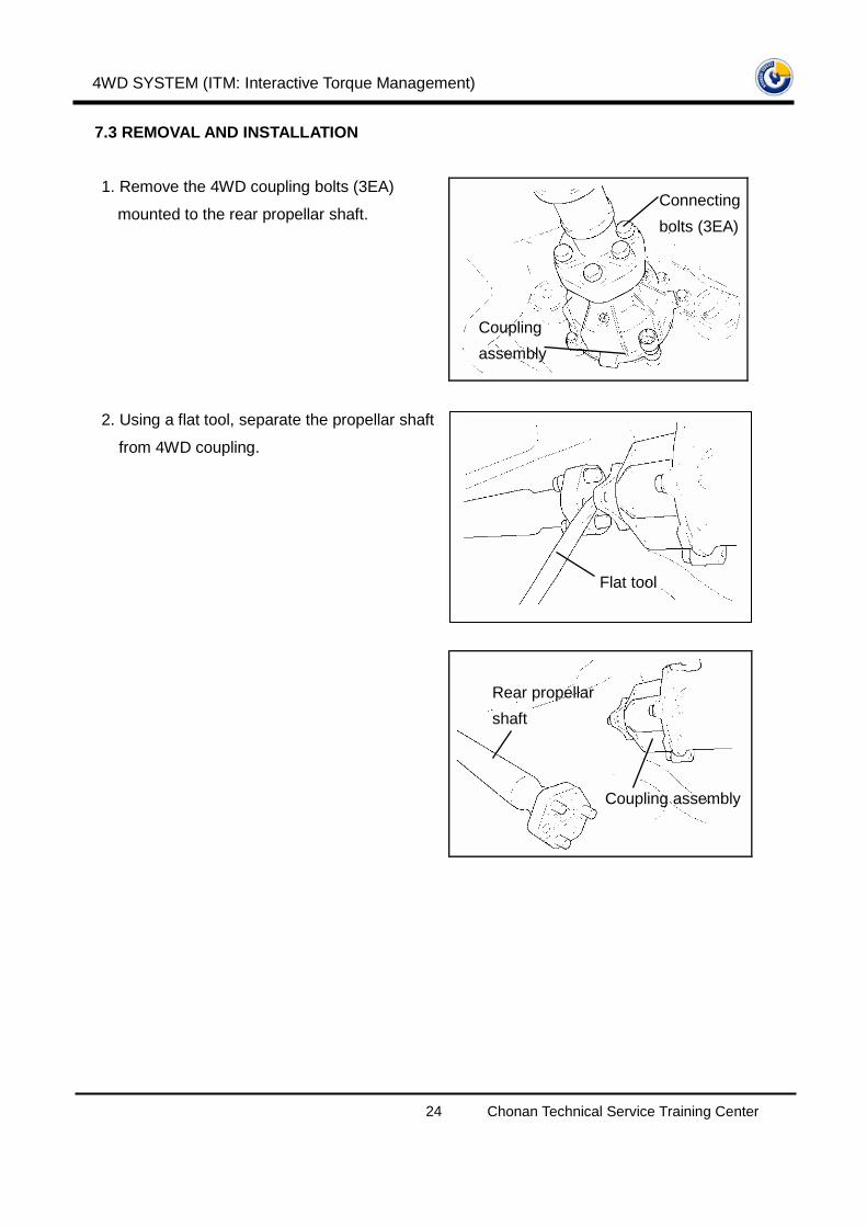
7.3 REMOVAL AND INSTALLATION
1. Remove the 4WD coupling bolts (3EA)
mounted to the rear propellar shaft.
2. Using a flat tool, separate the propellar shaft
from 4WD coupling.
Connecting
bolts (3EA)
Coupling
assembly
Flat tool
Rear propellar
shaft
Coupling assembly

4WD SYSTEM (ITM: Interactive Torque Management)
Chonan Technical Service Training Center 25
3. Remove the rear axle (Differential carrier)
bolts mounted to the 4WD coupling.
4. Remove the electric magnetic clutch
connector.
5. Using a flat tool, separate the 4WD coupling
assembly from the rear differential carrier.
6. Remove the 4WD coupling assembly.
7. Installation is the reverse of the removal.
Socket
Coupling
assembly Rear differential
carrier
Magnetic clutch connector
Flat tool
Rear differential carrier
Coupling assembly

4WD SYSTEM (ITM: Interactive Torque Management)
Chonan Technical Service Training Center 26
7.4 DISASSEMBLY
1. Remove the coupling flange mounting nut.
2. Remove the flange spacer.
3. Remove the coupling flange oil seal.
Nut
Flange
Spacer
Oil seal

4WD SYSTEM (ITM: Interactive Torque Management)
Chonan Technical Service Training Center 27
4. Using a general tool, 3-way puller, remove
the flange assembly.
5. Remove the flange oil seal using special tool
(09432-33200).
6. Remove the coupling case assembly.
1) Remove the coupling case oil seal.
NOTE
Insert the (-) driver between the oil seal
and the clutch housing, then remove the oil
seal.
3-way puller
Flange
Suitable tool
09432-33200
Oil seal
Press
�
Coupling
case
Clutch housing
Oil seal

4WD SYSTEM (ITM: Interactive Torque Management)
Chonan Technical Service Training Center 28
2) Remove the snap ring.
3) Remove the Electric Magnetic clutch
mounting nuts (3EA).
7. Remove the wave spring for fixing the back
plate and the secondary clutch assembly.
8. Remove the snap ring.
Snap ring
Magnetic
clutch
Wave
spring
Back plate
Snap
ring

4WD SYSTEM (ITM: Interactive Torque Management)
Chonan Technical Service Training Center 29
9. After removing the oil seal, remove the snap
ring.
10. Remove the back plate and the secondary
clutch assembly simultaneously using
special tool (09478-26100).
1) Separate the back plate from the input
shaft.
2) Remove the plates (10EA) and the discs
(10EA).
09478-26100
Back plate &
secondary
clutch
Back
plate
Plate
Disc

4WD SYSTEM (ITM: Interactive Torque Management)
Chonan Technical Service Training Center 30
3) Remove the armature.
4) Remove the input shaft.
11. Remove the steel balls (6EA) on the base
cam.
12. Remove the base cam.
Armature
Input shaft
Steel ball
Base cam

4WD SYSTEM (ITM: Interactive Torque Management)
Chonan Technical Service Training Center 31
13. Remove the thrust washer.
14. Remove the thrust race.
15. Remove the clutch of the primary clutch.
16. Remove the plate of the primary clutch.
NOTE
Additionally remove each 2EA discs and
plates alternately.
Thrust
washer
Thrust race
Snap ring
Plate

4WD SYSTEM (ITM: Interactive Torque Management)
Chonan Technical Service Training Center 32
7.5 REASSEMBLY
1. When reassembling the back plate oil seal,
reassemble it using a suitable tool.
2. In case of the coupling case oil seal, too,
reassemble it using a suitable tool.
3. When reassembling the 4WD coupling
assembly and the flange, too, reassemble
them using a suitable tool.
4. Install the flange oil seal using special tool.
Suitable tool
Oil seal
Suitable tool
Coupling case oil seal
Suitable tool Flange
09478-2600
Flange
Oil seal