48th aiaa/asme/asce/ahs/asc structures, structural ... · 48th aiaa/asme/asce/ahs/asc structures,...
TRANSCRIPT
48th AIAA/ASME/ASCE/AHS/ASC Structures, Structural Dynamics and Materials Conference, April 23–26, Waikiki, Hawaii
Novel Multistable Corrugated Structures
Alex D. Norman,∗ Simon D. Guest † and Keith A. Seffen ‡
Cambridge University, Engineering Department, Trumpington Street, Cambridge, CB2 1PZ, UK
We have been investigating the properties, behaviour and stability of multistable opencorrugated shells. This multistability arises from the interaction between internal pre-stresses created during forming and non-linear geometrical changes during deformation.Two modes of bistability are described here: prestressed corrugated shells which, whenbuckled, can coil up into a tube repeatably and reversibly, and corrugated sheets with aglobal cylindrical curvature, which is stable in either of two symmetric directions. Bothmodes can be present at the same time, creating a tristable shell. Using simplified analyticalelastic models, we homogenise the properties of the shells through simultaneously consid-ering the material on two scales: the ‘local’ scale of the isotropic material and the ‘global’scale of the corrugated sheet, which is then modelled as a homogenised, flat, anisotropicsheet. The models produce similar behaviour to our prototypes, and have taught us howto incorporate or eradicate the various modes at will. The insights and methods developedfrom these simple models are paving the way to developing more complex corrugated formswith even more general and interesting shape-changing characteristics.
Nomenclature
θ Angle (degrees ◦)κ Curvature (m−1)λ Corrugation wavelength (m)ν Poisson’s ratioa Corrugation amplitude at a point, measured from the mid-plane of the corrugated sheetc Corrugation curvature (m−1)t Local shell thicknessD Bending stiffness (N m)E Young’s Modulus (N m−2)M Bending moment per unit length (N)U Energy per unit area (N m−1)Subscripts & superscripts() Dimensionless property() Mean average over the material area/length()M Value at a local energy minimum (i.e. a stable point)
I. Introduction
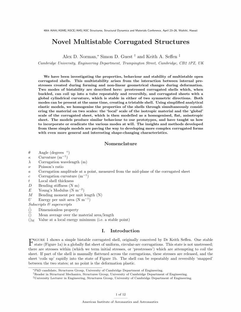
Figure 1 shows a simple bistable corrugated shell, originally conceived by Dr Keith Seffen. One stablestate (Figure 1a) is a globally flat sheet of uniform, circular-arc corrugations. This state is not unstressed;
there are stresses within (which we term initial stresses, or ‘prestresses’) which are attempting to coil thesheet. If part of the shell is manually flattened across the corrugations, these stresses are released, and thesheet ‘coils up’ rapidly into the state of Figure 1b. The shell can be repeatably and reversibly ‘snapped’between the two states; at no point is the deformation plastic.
∗PhD candidate, Structures Group, University of Cambridge Department of Engineering.†Reader in Structural Mechanics, Structures Group, University of Cambridge Department of Engineering.‡University Lecturer in Engineering, Structures Group, University of Cambridge Department of Engineering.
1 of 12
American Institute of Aeronautics and Astronautics
(a) In corrugated sheet form (b) The ‘coiled’ mode
Figure 1: A typical bistable shell. A bending prestress is held in equilibrium by the moment arm of themembrane stresses in the corrugated sheet (left): when the corrugations are elastically flattened, theprestresses are released and the sheet coils up.
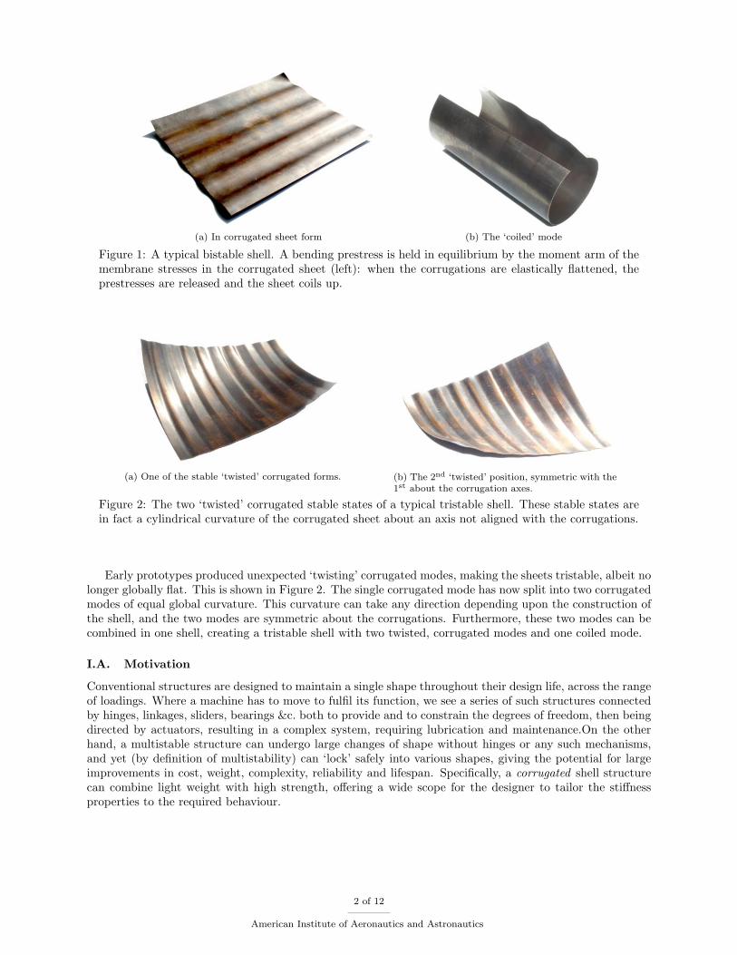
(a) One of the stable ‘twisted’ corrugated forms. (b) The 2nd ‘twisted’ position, symmetric with the1st about the corrugation axes.
Figure 2: The two ‘twisted’ corrugated stable states of a typical tristable shell. These stable states arein fact a cylindrical curvature of the corrugated sheet about an axis not aligned with the corrugations.
Early prototypes produced unexpected ‘twisting’ corrugated modes, making the sheets tristable, albeit nolonger globally flat. This is shown in Figure 2. The single corrugated mode has now split into two corrugatedmodes of equal global curvature. This curvature can take any direction depending upon the construction ofthe shell, and the two modes are symmetric about the corrugations. Furthermore, these two modes can becombined in one shell, creating a tristable shell with two twisted, corrugated modes and one coiled mode.
I.A. Motivation
Conventional structures are designed to maintain a single shape throughout their design life, across the rangeof loadings. Where a machine has to move to fulfil its function, we see a series of such structures connectedby hinges, linkages, sliders, bearings &c. both to provide and to constrain the degrees of freedom, then beingdirected by actuators, resulting in a complex system, requiring lubrication and maintenance.On the otherhand, a multistable structure can undergo large changes of shape without hinges or any such mechanisms,and yet (by definition of multistability) can ‘lock’ safely into various shapes, giving the potential for largeimprovements in cost, weight, complexity, reliability and lifespan. Specifically, a corrugated shell structurecan combine light weight with high strength, offering a wide scope for the designer to tailor the stiffnessproperties to the required behaviour.
2 of 12
American Institute of Aeronautics and Astronautics
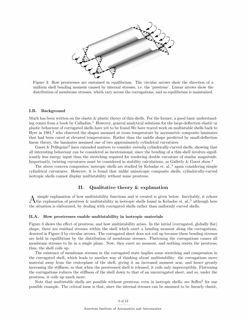
Figure 3: How prestresses are sustained in equilibrium. The circular arrows show the direction of auniform shell bending moment caused by internal stresses, i.e. the ‘prestress’. Linear arrows show thedistribution of membrane stresses, which vary across the corrugations, and so equilibrium is maintained.
I.B. Background
Much has been written on the elastic & plastic theory of thin shells. For the former, a good basic understand-ing comes from a book by Calladine.1 However, general analytical solutions for the large-deflection elastic orplastic behaviour of corrugated shells have yet to be found.We have traced work on multistable shells back toHyer in 1981,2 who observed the shapes assumed at room temperature by asymmetric composite laminatesthat had been cured at elevated temperatures. Rather than the saddle shape predicted by small-deflectionlinear theory, the laminates assumed one of two approximately cylindrical curvatures.
Guest & Pellegrino3 have extended matters to consider initially cylindrically-curved shells, showing thatall interesting behaviour can be considered as inextensional, since the bending of a thin shell involves signif-icantly less energy input than the stretching required for rendering double curvature of similar magnitude.Importantly, twisting curvatures must be considered in stability calculations, as Galletly & Guest show.4
The above concern composites; isotropic shells are studied by Kebadze et. al.,5 again considering simplecylindrical curvatures. However, it is found that unlike anisotropic composite shells, cylindrically-curvedisotropic shells cannot display multistability without some prestress.
II. Qualitative theory & explanation
A simple explanation of how multistability functions and is created is given below. Inevitably, it echoesthe explanation of prestress & multistability in isotropic shells found in Kebadze et. al.,5 although here
the situation is elaborated, by dealing with corrugated shells rather than uniformly curved shells.
II.A. How prestresses enable multistability in isotropic materials
Figure 3 shows the effect of prestress, and how multistability arises. In the initial (corrugated, globally flat)shape, there are residual stresses within the shell which exert a bending moment along the corrugations,denoted in Figure 3 by circular arrows. The corrugated sheet does not coil up because these bending stressesare held in equilibrium by the distribution of membrane stresses. Flattening the corrugations causes allmembrane stresses to lie in a single plane. Now, they exert no moment, and nothing resists the prestress;thus, the shell coils up.
The existence of membrane stresses in the corrugated state implies some stretching and compression inthe corrugated shell, which leads to another way of thinking about multistability: the corrugations movematerial away from the centreplane of the shell, giving it an increased moment arm, and hence greatlyincreasing the stiffness, so that when the prestressed shell is released, it coils only imperceptibly. Flatteningthe corrugations reduces the stiffness of the shell down to that of an uncorrugated sheet, and so, under theprestress, it coils up much more.
Note that multistable shells are possible without prestress, even in isotropic shells; see Seffen6 for onepossible example. The critical issue is that, since the internal stresses can be assumed to be linearly elastic,
3 of 12
American Institute of Aeronautics and Astronautics

any distortion mechanism in which the force-displacement curve is also linear (i.e. the stiffness is constantover large deflections) will provide only one equilibrium solution. Therefore, multistability can only arisewhere, due (for example) to geometrical effects, the force-displacement curve is nonlinear.
II.B. The method of construction
If a multistable shell is not prestressed, construction is a straightforward matter of pressing or otherwiseforming the desired shape. However, if prestresses must be built in, the shell is first pressed into the shapeinto which the prestresses (when released) deform it. The structure is then deformed plastically to createthe new shape; this deformation will affect the prestresses, but not remove them.
When we construct our prototypes, this final plastic deformation must be performed cold, so as to preservethe residual stresses. Most prototypes were formed from a Copper-Beryllium alloy, chosen for its high yieldstrain; shim steel has also been used successfully.
III. Analytical modelling
Simple analysis is needed to explain the observed behaviour in a way consistent with general elastic theory.Here, we set up two simple elastic models which take what we believe to be the starting conditions for
bistability, and then evaluate the internal energy as the shape of the shell varies. We expect to see localenergy minima corresponding to the stable shapes observed.
The following models do not consider the method by which the shells are formed. We have found bothupper-bound and lower-bound analyses to be inadequate to predict the final behaviour from the formingprocess (or, in similar fashion, to specify the forming process for a desired final behaviour), and have thereforeproduced a plastic flow model, assuming an Elastic-Perfectly Plastic (EPP) material that yields to a Trescacriterion. This plastic flow model has provided a useful insight into the formation process and the resultinginternal stresses, but they are not part of the subject of this paper: see Norman’s first year PhD report.7
It is trivial to combine the two models here to describe tristable shells, which we leave to the reader.
III.A. Elastic principles
Definitions of curvature are identical to those of Calladine.1 This analysis assumes that the material islinear-elastic, obeying Hooke’s law with a Young’s modulus E and a Poisson’s ratio ν. Since the shell is thin,plane stress behaviour can be assumed. Accordingly, Calladine1 assembles the following generalised Hooke’slaw for an isotropic shell in bending (for anisotropic materials, the bending stiffness matrix D changes); Mxx −Mxx0
Myy −Myy0
Mxy −Mxy0
= M −M0 = D(κ− κ0) = D
1 ν 0ν 1 00 0 1−ν
2
κxx − κxx0
κyy − κyy0
2(κxy − κxy0)
(1)
where D is the shell bending stiffness, defined by
D =Et3
12(1− ν2)(2)
Defining the change in curvature k = κ − κ0, the elastic strain energy density at a given point for a givenstate is the integral of the work done MTk over deformation from the initial state to that state. This is aconservative system, and therefore history-independent; the energy density U relative to the initial state κ0,M0 is
U =12kTDk + MT
0 k (3)
Remember that D can be a general anisotropic matrix, over and above the isotropic form.One condition of stability is that the equilibrium states have positive stiffness, thereby equating to local
energy minima. This can be expanded into two specific criteria;
1. for equilibrium, there must be no mechanism driving the system in any direction; therefore, the localenergy gradient (partial derivatives with respect to any shape factors) must be zero, and
4 of 12
American Institute of Aeronautics and Astronautics

2. for stability, the stiffness matrix must be positive definite at that point, so that any small deformationwill place the structure in a state from which it has a direct mechanism back to the previous form.
Equilibrium points which do not fulfil the second criteria come in three forms:
1. maxima, with all second-order derivatives zero or negative: they are unstable, and the structure maydeform in any direction;
2. saddle points with some negative second-order derivatives and some positive, which are unstable onlyin one direction, and stable in orthogonal directions;
3. metastable points: the second derivatives are zero in all directions, and the structure has zero stiffness.
This can all be determined analytically. However, once the equilibrium points are found, it is quicker toexamine a contour plot of energy to determine whether they are minima, maxima, saddles or metastable.
III.B. The elastic properties of corrugated sheets
The fundamental concept used to simplify the problem is the distinction between two scales: a ‘global’ scale,in which the corrugated sheet is rendered as a flat or developable sheet with anisotropic properties, andthe ‘local’ scale within the corrugations, where the sheet is isotropic. While a global curvature along thecorrugations will produce local tensions & strains, the strain energy within the sheet due to these strains isthe same as the purely bending strain energy of the anisotropic global sheet, and the complex problem ofnon-zero Gaussian curvature on the local scale is turned into the simpler problem of developable curvatureon the global scale. Only changes to the corrugation profile itself need be considered at the local scale,and this is, again, purely a bending effect. No net tension or compression is applied to the shells in theseanalyses.
The bending stiffness of the corrugated sheet in the y direction is the same as the local value D. Inaddition, the global twisting stiffness takes the local value (1− ν)D/2 and the Poisson coupling of curvaturein the x and y directions remains at νD, as for the isotropic sheet. Only the bending stiffness along thecorrugations is affected by the presence of the corrugations. In that direction, the local stiffness D isaugmented by the moment-arm of the material about the central plane, giving an additional stiffness αD,where α is a function of the shape of the corrugations. This gives a new stiffness matrix
D =
(1 + α)D νD 0νD D 00 0 1−ν
2 D
(4)
If we were to consider stretching of the global sheet, we would have to develop a much more sophisticatedmodel, since (for a corrugated sheet) stretching across the corrugations has a significant effect on bendingstiffness along them.
III.C. Elastic model 1: coiling bistability
This model deals purely with the behaviour of a flat corrugated sheet in which prestress tends to coil it up,and does not consider twist deformation. A sheet is modelled as having corrugations that run parallel to thex axis of the sheet. These corrugations are taken to be composed of alternating circular arcs, curving in they direction.
III.C.1. Equations
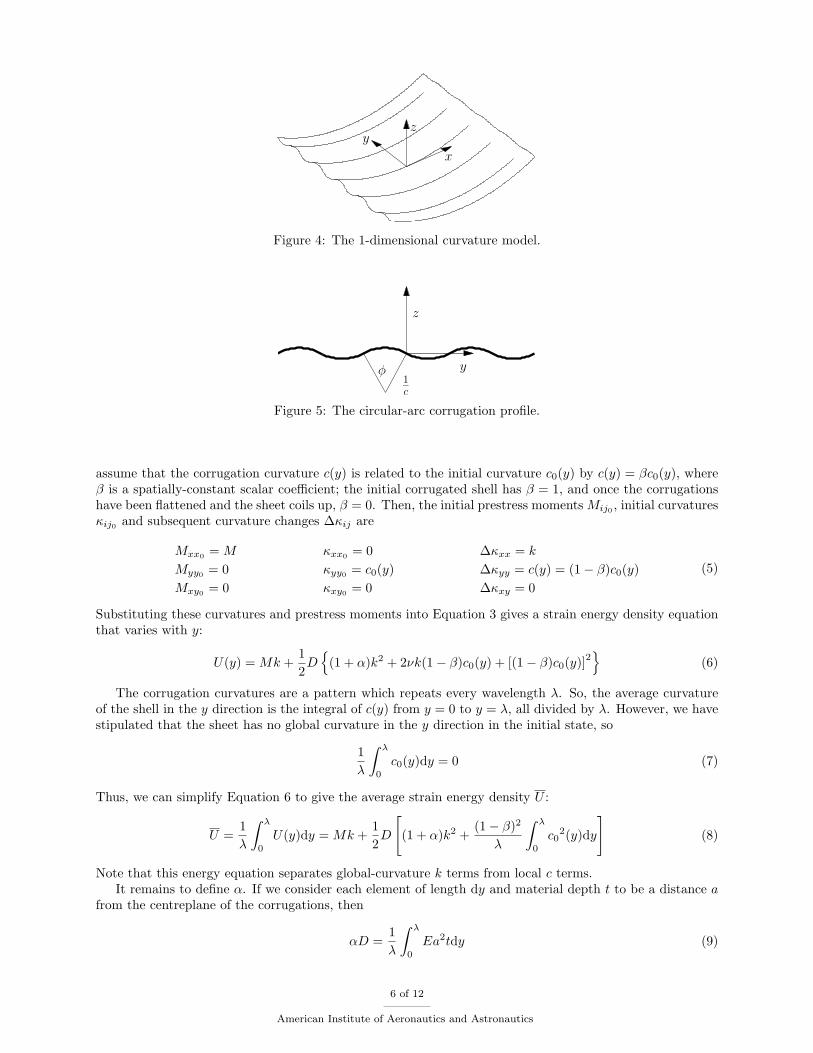
Figure 4 shows a section from a corrugated sheet in which edge effects are neglected. This figure shows simul-taneously the y-direction corrugation curvature of the corrugated mode and the global x-direction curvatureof the coiled mode, although we expect to find that the stable states have just one or the other present withnon-negligible magnitude. The global curvature in the x direction is defined as k. The corrugation curvaturevaries in the y direction, and is termed c(y).
The initial state is taken to be the corrugated mode (k = 0), and the corrugation takes some initial valuec0(y). There is a prestress moment M purely in the direction of the corrugations. From this initial state,
5 of 12
American Institute of Aeronautics and Astronautics
x
z
y
Figure 4: The 1-dimensional curvature model.
y
z
φ1
c
Figure 5: The circular-arc corrugation profile.
assume that the corrugation curvature c(y) is related to the initial curvature c0(y) by c(y) = βc0(y), whereβ is a spatially-constant scalar coefficient; the initial corrugated shell has β = 1, and once the corrugationshave been flattened and the sheet coils up, β = 0. Then, the initial prestress moments Mij0 , initial curvaturesκij0 and subsequent curvature changes ∆κij are
Mxx0 = M
Myy0 = 0Mxy0 = 0
κxx0 = 0κyy0 = c0(y)κxy0 = 0
∆κxx = k
∆κyy = c(y) = (1− β)c0(y)∆κxy = 0
(5)
Substituting these curvatures and prestress moments into Equation 3 gives a strain energy density equationthat varies with y:
U(y) = Mk +12D
{(1 + α)k2 + 2νk(1− β)c0(y) + [(1− β)c0(y)]2
}(6)
The corrugation curvatures are a pattern which repeats every wavelength λ. So, the average curvatureof the shell in the y direction is the integral of c(y) from y = 0 to y = λ, all divided by λ. However, we havestipulated that the sheet has no global curvature in the y direction in the initial state, so
1λ
∫ λ
0
c0(y)dy = 0 (7)
Thus, we can simplify Equation 6 to give the average strain energy density U :
U =1λ
∫ λ
0
U(y)dy = Mk +12D
[(1 + α)k2 +
(1− β)2
λ
∫ λ
0
c02(y)dy
](8)
Note that this energy equation separates global-curvature k terms from local c terms.It remains to define α. If we consider each element of length dy and material depth t to be a distance a
from the centreplane of the corrugations, then
αD =1λ
∫ λ
0
Ea2tdy (9)
6 of 12
American Institute of Aeronautics and Astronautics
Corrugation flattening 1− βD
imen
sionle
sspre
stre
ssm
om
entM
φ0 = 57 ◦
φ0 = 7 ◦
Constant-prestress lineStable equilibrium pointsUnstable equilibrium points
0 0.2 0.4 0.6 0.8 10
2
4
6
8
10
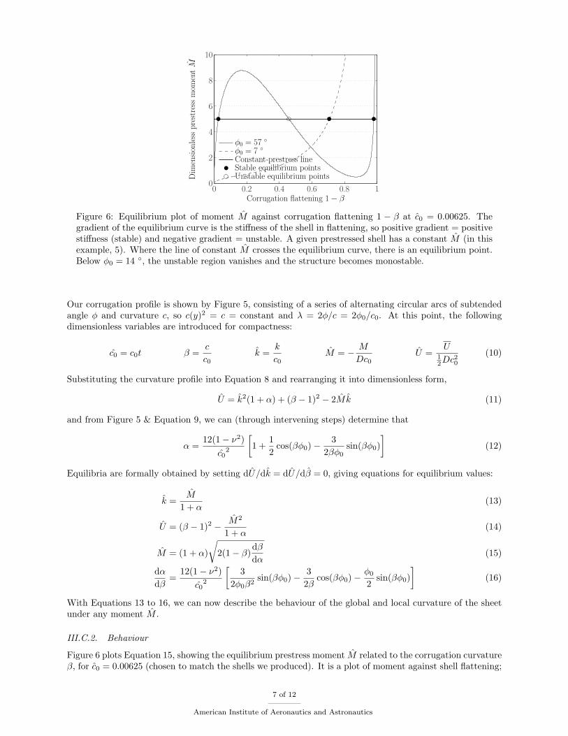
Figure 6: Equilibrium plot of moment M against corrugation flattening 1 − β at c0 = 0.00625. Thegradient of the equilibrium curve is the stiffness of the shell in flattening, so positive gradient = positivestiffness (stable) and negative gradient = unstable. A given prestressed shell has a constant M (in thisexample, 5). Where the line of constant M crosses the equilibrium curve, there is an equilibrium point.Below φ0 = 14 ◦, the unstable region vanishes and the structure becomes monostable.
Our corrugation profile is shown by Figure 5, consisting of a series of alternating circular arcs of subtendedangle φ and curvature c, so c(y)2 = c = constant and λ = 2φ/c = 2φ0/c0. At this point, the followingdimensionless variables are introduced for compactness:
c0 = c0t β =c
c0k =
k
c0M = − M
Dc0U =
U12Dc2
0
(10)
Substituting the curvature profile into Equation 8 and rearranging it into dimensionless form,
U = k2(1 + α) + (β − 1)2 − 2Mk (11)
and from Figure 5 & Equation 9, we can (through intervening steps) determine that
α =12(1− ν2)
c02
[1 +
12
cos(βφ0)−3
2βφ0sin(βφ0)
](12)
Equilibria are formally obtained by setting dU/dk = dU/dβ = 0, giving equations for equilibrium values:
k =M
1 + α(13)
U = (β − 1)2 − M2
1 + α(14)
M = (1 + α)
√2(1− β)
dβ
dα(15)
dα
dβ=
12(1− ν2)c0
2
[3
2φ0β2sin(βφ0)−
32β
cos(βφ0)−φ0
2sin(βφ0)
](16)
With Equations 13 to 16, we can now describe the behaviour of the global and local curvature of the sheetunder any moment M .
III.C.2. Behaviour
Figure 6 plots Equation 15, showing the equilibrium prestress moment M related to the corrugation curvatureβ, for c0 = 0.00625 (chosen to match the shells we produced). It is a plot of moment against shell flattening;
7 of 12
American Institute of Aeronautics and Astronautics
Dimensionless global curvature k
Dim
ensi
onle
sspre
stre
ssm
om
entM
φ0 = 7 ◦
φ0 = 14 ◦
φ0 = 29 ◦
φ0 = 57 ◦
10−2 100
10−1
100
101
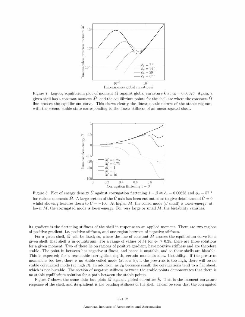
Figure 7: Log-log equilibrium plot of moment M against global curvature k at c0 = 0.00625. Again, agiven shell has a constant moment M , and the equilibrium points for the shell are where the constant-Mline crosses the equilibrium curve. This shows clearly the linear-elastic nature of the stable regimes,with the second stable state corresponding to the linear stiffness of an uncorrugated sheet.
Corrugation flattening 1− β
Dim
ensi
onle
ssen
ergy
U
M = 0.25M = 0.75M = 1M = 5M = 10
0 0.2 0.4 0.6 0.8 1-100
-50
-20
-0.5
0
0.5
1
Figure 8: Plot of energy density U against corrugation flattening 1− β at c0 = 0.00625 and φ0 = 57 ◦
for various moments M . A large section of the U axis has been cut out so as to give detail around U = 0whilst showing features down to U = −100. At higher M , the coiled mode (β small) is lower-energy; atlower M , the corrugated mode is lower-energy. For very large or small M , the bistability vanishes.
its gradient is the flattening stiffness of the shell in response to an applied moment. There are two regionsof positive gradient, i.e. positive stiffness, and one region between of negative stiffness.
For a given shell, M will be fixed; so, where the line of constant M crosses the equilibrium curve for agiven shell, that shell is in equilibrium. For a range of values of M for φ0 ≥ 0.25, there are three solutionsfor a given moment. Two of these lie on regions of positive gradient, have positive stiffness and are thereforestable. The point in between has negative stiffness, and hence is unstable, and so these shells are bistable.This is expected; for a reasonable corrugation depth, certain moments allow bistability. If the prestressmoment is too low, there is no stable coiled mode (at low β); if the prestress is too high, there will be nostable corrugated mode (at high β). In addition, as φ0 becomes small, the corrugations tend to a flat sheet,which is not bistable. The section of negative stiffness between the stable points demonstrates that there isno stable equilibrium solution for a path between the stable points.
Figure 7 shows the same data but plots M against global curvature k. This is the moment-curvatureresponse of the shell, and its gradient is the bending stiffness of the shell. It can be seen that the corrugated
8 of 12
American Institute of Aeronautics and Astronautics
Initial dimensionless corrugation curvature c0
Init
ialco
rruga
tion
angl
eφ
0/◦
Bistability possible
(if material constraints allow)
Corrugations too shallow
for bistability
10−3 10−2 10−10
30
60
90
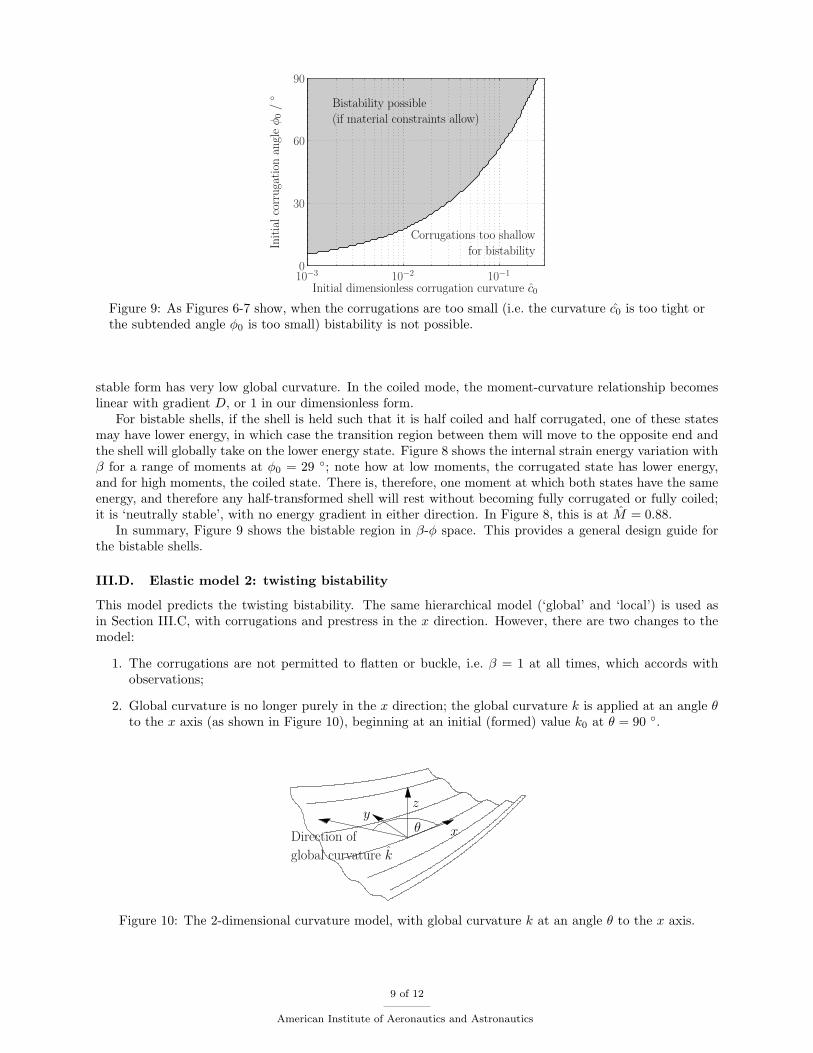
Figure 9: As Figures 6-7 show, when the corrugations are too small (i.e. the curvature c0 is too tight orthe subtended angle φ0 is too small) bistability is not possible.
stable form has very low global curvature. In the coiled mode, the moment-curvature relationship becomeslinear with gradient D, or 1 in our dimensionless form.
For bistable shells, if the shell is held such that it is half coiled and half corrugated, one of these statesmay have lower energy, in which case the transition region between them will move to the opposite end andthe shell will globally take on the lower energy state. Figure 8 shows the internal strain energy variation withβ for a range of moments at φ0 = 29 ◦; note how at low moments, the corrugated state has lower energy,and for high moments, the coiled state. There is, therefore, one moment at which both states have the sameenergy, and therefore any half-transformed shell will rest without becoming fully corrugated or fully coiled;it is ‘neutrally stable’, with no energy gradient in either direction. In Figure 8, this is at M = 0.88.
In summary, Figure 9 shows the bistable region in β-φ space. This provides a general design guide forthe bistable shells.
III.D. Elastic model 2: twisting bistability
This model predicts the twisting bistability. The same hierarchical model (‘global’ and ‘local’) is used asin Section III.C, with corrugations and prestress in the x direction. However, there are two changes to themodel:
1. The corrugations are not permitted to flatten or buckle, i.e. β = 1 at all times, which accords withobservations;
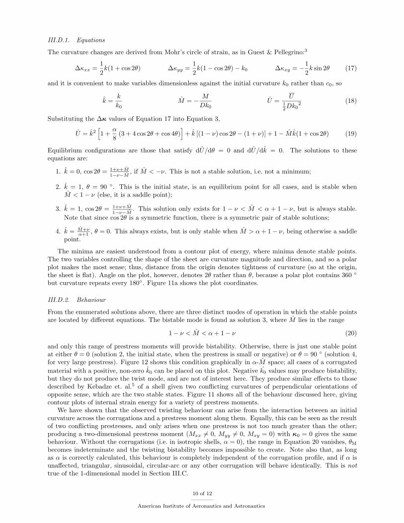
2. Global curvature is no longer purely in the x direction; the global curvature k is applied at an angle θto the x axis (as shown in Figure 10), beginning at an initial (formed) value k0 at θ = 90 ◦.
x
zy
θDirection of
global curvature k
Figure 10: The 2-dimensional curvature model, with global curvature k at an angle θ to the x axis.
9 of 12
American Institute of Aeronautics and Astronautics
III.D.1. Equations
The curvature changes are derived from Mohr’s circle of strain, as in Guest & Pellegrino:3
∆κxx =12k(1 + cos 2θ) ∆κyy =
12k(1− cos 2θ)− k0 ∆κxy = −1
2k sin 2θ (17)
and it is convenient to make variables dimensionless against the initial curvature k0 rather than c0, so
k =k
k0M = − M
Dk0U =
U12Dk0
2 (18)
Substituting the ∆κ values of Equation 17 into Equation 3,
U = k2[1 +
α
8(3 + 4 cos 2θ + cos 4θ)
]+ k [(1− ν) cos 2θ − (1 + ν)] + 1− Mk(1 + cos 2θ) (19)
Equilibrium configurations are those that satisfy dU/dθ = 0 and dU/dk = 0. The solutions to theseequations are:
1. k = 0, cos 2θ = 1+ν+M1−ν−M
, if M < −ν. This is not a stable solution, i.e. not a minimum;
2. k = 1, θ = 90 ◦. This is the initial state, is an equilibrium point for all cases, and is stable whenM < 1− ν (else, it is a saddle point);
3. k = 1, cos 2θ = 1+ν+M1−ν−M
. This solution only exists for 1 − ν < M < α + 1 − ν, but is always stable.Note that since cos 2θ is a symmetric function, there is a symmetric pair of stable solutions;
4. k = M+να+1 , θ = 0. This always exists, but is only stable when M > α + 1− ν, being otherwise a saddle
point.
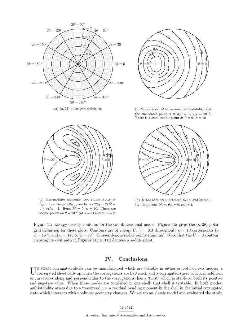
The minima are easiest understood from a contour plot of energy, where minima denote stable points.The two variables controlling the shape of the sheet are curvature magnitude and direction, and so a polarplot makes the most sense; thus, distance from the origin denotes tightness of curvature (so at the origin,the sheet is flat). Angle on the plot, however, denotes 2θ rather than θ, because a polar plot contains 360 ◦
but curvature repeats every 180◦. Figure 11a shows the plot coordinates.
III.D.2. Behaviour
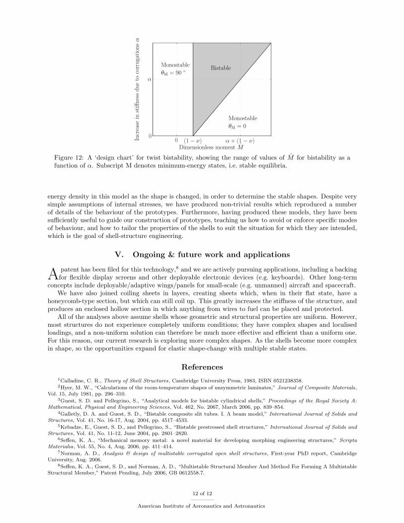
From the enumerated solutions above, there are three distinct modes of operation in which the stable pointsare located by different equations. The bistable mode is found as solution 3, where M lies in the range
1− ν < M < α + 1− ν (20)
and only this range of prestress moments will provide bistability. Otherwise, there is just one stable pointat either θ = 0 (solution 2, the initial state, when the prestress is small or negative) or θ = 90 ◦ (solution 4,for very large prestress). Figure 12 shows this condition graphically in α-M space; all cases of a corrugatedmaterial with a positive, non-zero k0 can be placed on this plot. Negative k0 values may produce bistability,but they do not produce the twist mode, and are not of interest here. They produce similar effects to thosedescribed by Kebadze et. al.5 of a shell given two conflicting curvatures of perpendicular orientations ofopposite sense, which are the two stable states. Figure 11 shows all of the behaviour discussed here, givingcontour plots of internal strain energy for a variety of prestress moments.
We have shown that the observed twisting behaviour can arise from the interaction between an initialcurvature across the corrugations and a prestress moment along them. Equally, this can be seen as the resultof two conflicting prestresses, and only arises when one prestress is not too much greater than the other;producing a two-dimensional prestress moment (Mxx 6= 0, Myy 6= 0, Mxy = 0) with κ0 = 0 gives the samebehaviour. Without the corrugations (i.e. in isotropic shells, α = 0), the range in Equation 20 vanishes, θM
becomes indeterminate and the twisting bistability becomes impossible to create. Note also that, as longas α is correctly calculated, this behaviour is completely independent of the corrugation profile, and if α isunaffected, triangular, sinusoidal, circular-arc or any other corrugation will behave identically. This is nottrue of the 1-dimensional model in Section III.C.
10 of 12
American Institute of Aeronautics and Astronautics
k = 0.5
k = 1
k = 1.5
k = 2
2θ = 30◦
2θ = 210◦
2θ = 60◦
2θ = 240◦
2θ = 90◦
2θ = 270◦
2θ = 120◦
2θ = 300◦
2θ = 150◦
2θ = 330◦
2θ = 180◦ 2θ = 0
(a) (κ, 2θ) polar grid definition.
θ = 90◦ θ = 0
0.10.25
0.51
25 10
20
30
40
(b) Monostable: M is too small for bistability, and
the one stable point is at kM = 1, θM = 90 ◦.There is a small saddle point at k = 0. α = 10
θ = 90◦ θ = 0
−1.8−1.5−0.75
0
−
1.5
−
0.75
02 5 10
15
20
(c) Intermediate moments; two stable states at
kM = 1, at angle ±θM given by cos 2θM = 2(M −1 + ν)/α − 1. Here, M = 5, α = 10. There are
saddle points on θ = 90 ◦ (at k = 1) and on θ = 0.
θ = 90◦ θ = 0
0−1
−3
−7
−11
−
15−
17 −
19
−20
−20.2
5(d) M has here been increased to 15, and bistabil-
ity disappears. Now, θM = 0, kM > 1.
Figure 11: Energy-density contours for the two-dimensional model. Figure 11a gives the (κ, 2θ) polargrid definition for these plots. Contours are of energy U . ν = 0.3 throughout. α = 10 corresponds toφ = 15 ◦, and α = 145 to φ = 30◦. Crosses denote stable points (minima). Note that the U = 0 contourcrossing its own path in Figures 11c & 11d denotes a saddle point.
IV. Conclusions
Uniform corrugated shells can be manufactured which are bistable in either or both of two modes: acorrugated sheet coils up when the corrugations are flattened, and a corrugated sheet which, in addition
to curvatures along and perpendicular to the corrugations, has a ‘twist’ which is stable at both its positiveand negative value. When these modes are combined in one shell, that shell is tristable. In both modes,multistability arises due to a ‘prestress’, i.e. a residual bending moment in the shell in the initial corrugatedstate which interacts with nonlinear geometry changes. We set up an elastic model and evaluated the strain
11 of 12
American Institute of Aeronautics and Astronautics
Dimensionless moment M
Incr
ease
inst
iffnes
sdue
toco
rruga
tion
sα
BistableMonostable
θM = 90 ◦
Monostable
θM = 0
0 (1− ν) α + (1− ν)0
α
Figure 12: A ‘design chart’ for twist bistability, showing the range of values of M for bistability as afunction of α. Subscript M denotes minimum-energy states, i.e. stable equilibria.
energy density in this model as the shape is changed, in order to determine the stable shapes. Despite verysimple assumptions of internal stresses, we have produced non-trivial results which reproduced a numberof details of the behaviour of the prototypes. Furthermore, having produced these models, they have beensufficiently useful to guide our construction of prototypes, teaching us how to avoid or enforce specific modesof behaviour, and how to tailor the properties of the shells to suit the situation for which they are intended,which is the goal of shell-structure engineering.
V. Ongoing & future work and applications
A patent has been filed for this technology,8 and we are actively pursuing applications, including a backingfor flexible display screens and other deployable electronic devices (e.g. keyboards). Other long-term
concepts include deployable/adaptive wings/panels for small-scale (e.g. unmanned) aircraft and spacecraft.We have also joined coiling sheets in layers, creating sheets which, when in their flat state, have a
honeycomb-type section, but which can still coil up. This greatly increases the stiffness of the structure, andproduces an enclosed hollow section in which anything from wires to fuel can be placed and protected.
All of the analyses above assume shells whose geometric and structural properties are uniform. However,most structures do not experience completely uniform conditions; they have complex shapes and localisedloadings, and a non-uniform solution can therefore be much more effective and efficient than a uniform one.For this reason, our current research is exploring more complex shapes. As the shells become more complexin shape, so the opportunities expand for elastic shape-change with multiple stable states.
References
1Calladine, C. R., Theory of Shell Structures, Cambridge University Press, 1983, ISBN 0521238358.2Hyer, M. W., “Calculations of the room-temperature shapes of unsymmetric laminates,” Journal of Composite Materials,
Vol. 15, July 1981, pp. 296–310.3Guest, S. D. and Pellegrino, S., “Analytical models for bistable cylindrical shells,” Proceedings of the Royal Society A:
Mathematical, Physical and Engineering Sciences, Vol. 462, No. 2067, March 2006, pp. 839–854.4Galletly, D. A. and Guest, S. D., “Bistable composite slit tubes. I. A beam model,” International Journal of Solids and
Structures, Vol. 41, No. 16-17, Aug. 2004, pp. 4517–4533.5Kebadze, E., Guest, S. D., and Pellegrino, S., “Bistable prestressed shell structures,” International Journal of Solids and
Structures, Vol. 41, No. 11-12, June 2004, pp. 2801–2820.6Seffen, K. A., “Mechanical memory metal: a novel material for developing morphing engineering structures,” Scripta
Materialia, Vol. 55, No. 4, Aug. 2006, pp. 411–414.7Norman, A. D., Analysis & design of multistable corrugated open shell structures, First-year PhD report, Cambridge
University, Aug. 2006.8Seffen, K. A., Guest, S. D., and Norman, A. D., “Multistable Structural Member And Method For Forming A Multistable
Structural Member,” Patent Pending, July 2006, GB 0612558.7.
12 of 12
American Institute of Aeronautics and Astronautics