41515-ed 113 41505-ed - grieger-automation.com eng... · resistance up to 370 h (test operated...
TRANSCRIPT

41 515/113 ED 1/24
41 515/113 ED
OPERATING PRINCIPLE
— The solenoid operated directional control valves are in
compliance with ATEX 94/9/EC standards and are
suitable for the use in potentially explosive atmospheres,
that fall within the ATEX II 2GD either for gas or for dust
classif ication. See par. 4 for ATEX classif ication,
operating temperatures and electrical characteristics.
— These valves are direct operated type, ISO 4401-03
(CETOP 03) size and pilot operated type, CETOP P05,
ISO 4401-05 (CETOP R05), ISO 4401-07 (CETOP 07),
ISO 4401-08 (CETOP 08) and ISO 4401-10 (CETOP 10).
— With the valve and the distributor the statement of
conformity to the upmentioned standards is always
supplied.
— The DS3KD2 valves are supplied with a finishing surface
treatment (zinc-nickel) suitable to ensure a salt spray
resistance up to 370 h (test operated according to UNI EN
ISO 9227 standards and test evaluation operated
according to UNI EN ISO 10289 standards); for DSP*KD2
valves, this treatment is available upon request.
PERFORMANCES (working with mineral oil of viscosity of 36 cSt at 50°C)
DS3KD2 ISO 4401-03 (CETOP 03)
DSP5KD2 CETOP P05DSP5RKD2 ISO 4401-05 (CETOP R05)DSP7KD2 ISO 4401-07 (CETOP 07)DSP8KD2 ISO 4401-08 (CETOP 08)DSP10KD2 ISO 4401-10 (CETOP 10)
DS(P)*KD2 EXPLOSION-PROOF VERSION
SOLENOID OPERATEDDIRECTIONAL CONTROL VALVES
in compliance with ATEX 94/9/EC
TYPE EXAMINATION CERTIFICATE NUMBER: 1131-CEC 13 ATEX 030
DS3KD2DSP5KD2
DSP5RKD2DSP7KD2 DSP8KD2 DSP10KD2
Maximum operating pressure
P - A - B ports bar 350 320 350 350 350
T port 210 see operating limits at paragraph 7.2
Maximum flow from P port to A - B - T l/min
see operating
limits at
paragraph 2.2150 300 600 1100
Ambient temperature range °C -20 / +80 (NBR and FPM) -40 / +80 (NL)
Fluid temperature range °C -20 / +80 (NBR and FPM) -40 / +80 (NL)
Fluid viscosity range cSt 10 ÷ 400
Fluid contamination degree According to ISO 4406:1999 class 20/18/15
Recommended viscosity cSt 25
Mass single solenoid valve
double solenoid valvekg
1,8
2,8
6,8
7,8
8,6
9,6
15,5
16,5
52
53

41 515/113 ED 2/24
*KD2 1 - IDENTIFICATION OF DIRECT OPERATED SOLENOID VALVES DS3KD2
1.1 - Identification code
1.2 - Available spools
Spool type (see par. 1.2)
S* TA TB RK
SA* TA02 TB02
SB* TA23 TB23
Series No.: (the overall and mountingdimensions remain unchanged from 10 to 19)
D S 3 KD2 - / 10 - K9 /
Direct operated solenoidvalve
Size ISO 4401-03 (CETOP 03)
Seals:
For temperature range -20 / +80 °C
N = NBR seals for mineral oil (standard)
V = FPM seals for special fluids
For temperature range -40 / +80 °C
NL = seal for low temperatures (for mineral oil)
Power supply
D12 = 12 VD24 = 24 VD48 = 48 VD110 = 110 V
R120 = 120 VR240 = 240 V
Coil electrical connection:
electrical connection byterminal block
Connection type for cable gland
Available for upper connection:T01 = M20x1.5 - ISO 261T02 = Gk 1/2 - UNI EN 10226-2T03 = 1/2” NPT - ANSI B1.20.1(ex ANSI B2.1)
Available for side connection:S04 = M16x1.5 - ISO 261
(only for power supply D24)
S01 = M20x1.5 - ISO 261(available upon request only)
Version S*:
2 solenoids - 3 positions
with spring centering
Version TA:
1 solenoid side A
2 external positions
with return spring
Version TB:
1 solenoid side B
2 external positions
with return spring
Version SA*:
1 solenoid side A
2 positions (central + external)
with spring centering
Explosion-proof version, accordingto ATEX - II 2GD for gas or for dust (protection type of the coil: “d”)
Manual override:CM = manual override, bootprotected (standard for both Nand V seals - not available forNL seals)CB = blind ring nut (standardfor NL seals - available uponrequest for both N and V seals)CH = lever manual override
For dimension details of CBand CH versions, seeparagraph 16
Version RK:
2 solenoids - 2 positions
with mechanical retention
@ rectified current (RAC)
@ continuous current (DC)
Version SB*:
1 solenoid side B
2 positions (central + external)
with spring centering
NOTE: zinc-nickel standard finishing surface treatment.
NOTE: TA02/TB02 spool is not available
for RAC solenoid valves.
41 515/113 ED 3/24
*KD2
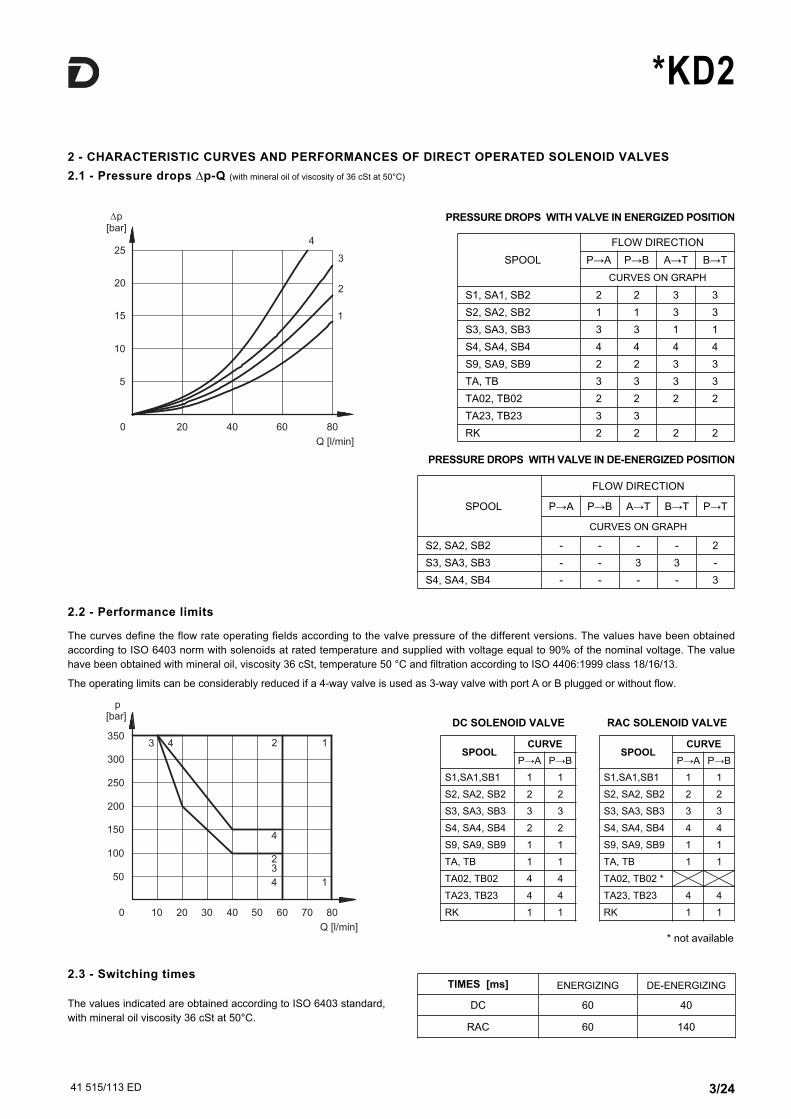
2.1 - Pressure drops ∆p-Q (with mineral oil of viscosity of 36 cSt at 50°C)
2 - CHARACTERISTIC CURVES AND PERFORMANCES OF DIRECT OPERATED SOLENOID VALVES
SPOOL
FLOW DIRECTION
P→A P→B A→T B→T
CURVES ON GRAPH
S1, SA1, SB2 2 2 3 3
S2, SA2, SB2 1 1 3 3
S3, SA3, SB3 3 3 1 1
S4, SA4, SB4 4 4 4 4
S9, SA9, SB9 2 2 3 3
TA, TB 3 3 3 3
TA02, TB02 2 2 2 2
TA23, TB23 3 3
RK 2 2 2 2
2.2 - Performance limits
PRESSURE DROPS WITH VALVE IN ENERGIZED POSITION
PRESSURE DROPS WITH VALVE IN DE-ENERGIZED POSITION
SPOOL
FLOW DIRECTION
P→A P→B A→T B→T P→T
CURVES ON GRAPH
S2, SA2, SB2 - - - - 2
S3, SA3, SB3 - - 3 3 -
S4, SA4, SB4 - - - - 3
The curves define the flow rate operating fields according to the valve pressure of the different versions. The values have been obtained
according to ISO 6403 norm with solenoids at rated temperature and supplied with voltage equal to 90% of the nominal voltage. The value
have been obtained with mineral oil, viscosity 36 cSt, temperature 50 °C and filtration according to ISO 4406:1999 class 18/16/13.
The operating limits can be considerably reduced if a 4-way valve is used as 3-way valve with port A or B plugged or without flow.
SPOOL CURVE
P→A P→B
S1,SA1,SB1 1 1
S2, SA2, SB2 2 2
S3, SA3, SB3 3 3
S4, SA4, SB4 2 2
S9, SA9, SB9 1 1
TA, TB 1 1
TA02, TB02 4 4
TA23, TB23 4 4
RK 1 1
2.3 - Switching times
The values indicated are obtained according to ISO 6403 standard,
with mineral oil viscosity 36 cSt at 50°C.
TIMES [ms] ENERGIZING DE-ENERGIZING
DC 60 40
RAC 60 140
SPOOL CURVE
P→A P→B
S1,SA1,SB1 1 1
S2, SA2, SB2 2 2
S3, SA3, SB3 3 3
S4, SA4, SB4 4 4
S9, SA9, SB9 1 1
TA, TB 1 1
TA02, TB02 *
TA23, TB23 4 4
RK 1 1
DC SOLENOID VALVE RAC SOLENOID VALVE
* not available
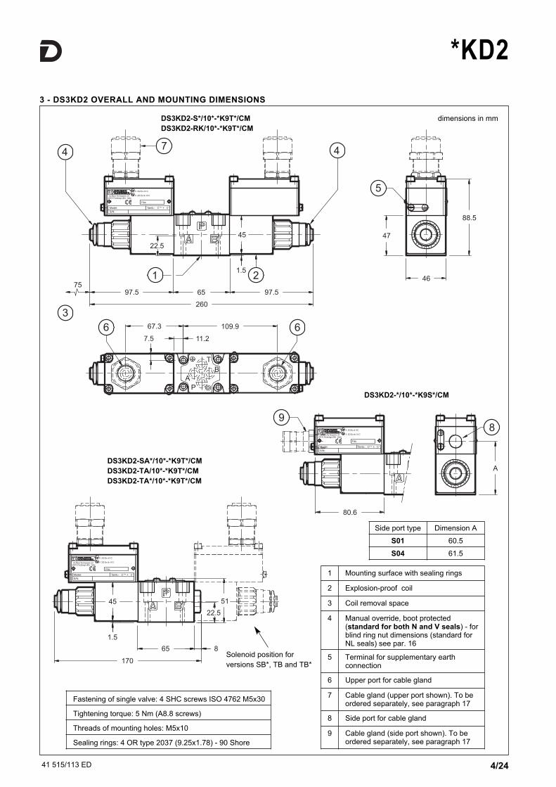
3 - DS3KD2 OVERALL AND MOUNTING DIMENSIONS
dimensions in mm
41 515/113 ED 4/24
*KD2
DS3KD2-S*/10*-*K9T*/CM
DS3KD2-RK/10*-*K9T*/CM
DS3KD2-SA*/10*-*K9T*/CM
DS3KD2-TA/10*-*K9T*/CM
DS3KD2-TA*/10*-*K9T*/CM
Fastening of single valve: 4 SHC screws ISO 4762 M5x30
Tightening torque: 5 Nm (A8.8 screws)
Threads of mounting holes: M5x10
Sealing rings: 4 OR type 2037 (9.25x1.78) - 90 Shore
1 Mounting surface with sealing rings
2 Explosion-proof coil
3 Coil removal space
4 Manual override, boot protected(standard for both N and V seals) - forblind ring nut dimensions (standard forNL seals) see par. 16
5 Terminal for supplementary earthconnection
6 Upper port for cable gland
7 Cable gland (upper port shown). To beordered separately, see paragraph 17
8 Side port for cable gland
9 Cable gland (side port shown). To beordered separately, see paragraph 17
Side port type Dimension A
S01 60.5
S04 61.5
Solenoid position for
versions SB*, TB and TB*
DS3KD2-*/10*-*K9S*/CM

41 515/113 ED 5/24
*KD2
MARKING FOR GASES, VAPOURS, MISTS
II 2G Ex d IIC T4 Gb (-40°C Ta +80°C)
EX: Specific marking of explosion protection as ATEX 94/9/EC
directive and related technical specification requests.
II: Group II for surface plants
2: Category 2 high protection, eligible for zone 1
(therefore also eligible for category 3 zone 2)
G: Type of atmosphere with gases, vapours, mists
Ex d: “d” protection type, explosion-proof case
IIC: Gas group
(therefore also eligible for group IIA and IIB)
T4: Temperature class (max surface temperature)
Gb: EPL protection level for electrical devices
-40°C Ta +80°C: Ambient temperature range
MARKING FOR DUSTS
II 2D Ex tb IIIC T154°C Db IP66/IP68 (-40°C Ta +80°C)
EX: Specific marking of explosion protection as ATEX 94/9/EC
directive and related technical specification requests.
II: Group II for surface plants
2: Category 2 high protection, eligible for zone 21
(therefore also eligible for category 3 zone 22)
D: Type of atmosphere with dusts
Ex tb : ‘tb’ protection type
IIIC:Dusts group
(therefore also eligible for group IIIA and IIIB)
T154°C: Temperature class (max surface temperature)
Db: EPL protection level for electrical devices
IP66/IP68: Valve IP degree
-40°C Ta +80°C: Ambient temperature range
4 - ATEX CLASSIFICATION, OPERATING TEMPERATURES AND ELECTRICAL CHARACTERISTICS
For valves suitable for application and installation in potentially explosive atmospheres, according to ATEX directive prescriptions,
Duplomatic certificated the combination valve-coil; the supply always includes the declaration of conformity to the directive and the
operating and maintenance manual, that contains all the informations needed for a correct use of the valve in potentially explosive
environments.
Coils assembled on these valves have been separately certified according to ATEX directive and so they are suitable for use in potentially
explosive atmospheres.
4.1 - Valve ATEX classification
The valves can be used for applications and installations in potentially explosive atmospheres that fall within either the ATEX II 2G or the ATEX
II 2D classification, with the follow marking:
4.2 - Coils ATEX classification
The coil of the explosion-proof valves is identified with its own tag, which carries the relative ATEX marking. The mechanical construction of
the coil housing is made in order to ensure its resistance to possible internal explosion and to avoid any explosion propagation to
the outside environment, matching an “Ex d” type protection (explosion-proof coil).
Moreover, the solenoid is designed to maintain its surface temperature below the limits specified to the relevant class.
The R* coils (for alternating current supply) contain a built-in rectifier bridge.
Here below you find the coils marking:
MARKING FOR GASES, VAPOURS, MISTS
II 2G IIC T4 Gb (-20°C Ta +80°C) for both N and V seals
II 2G IIC T4 Gb (-40°C Ta +80°C) for NL seals
EX: Specific marking of explosion protection as ATEX 94/9/EC
directive and related technical specification requests.
II: Group II for surface plants
2: Category 2 high protection, eligible for zone 1
(therefore also eligible for category 3 zone 2)
G: Type of atmosphere with gases, vapours, mists
IIC: Gas group
(therefore also eligible for group IIA and IIB)
T4: Temperature class (max surface temperature)
Gb: EPL protection level for electrical devices
-20°C Ta +80°C: Ambient temperature range for valves with both N
and V seals
-40°C Ta +80°C: Ambient temperature range for valves with NL
seals
MARKING FOR DUSTS
II 2D IIIC T154°C Db (-20°C Ta +80°C) for both N and V seals
II 2D IIIC T154°C Db (-40°C Ta +80°C) for NL seals
EX: Specific marking of explosion protection as ATEX 94/9/EC
directive and related technical specification requests.
II: Group II for surface plants
2: Category 2 high protection, eligible for zone 21
(therefore also eligible for category 3 zone 22)
D: Type of atmosphere with dusts
IIIC:Dusts group
(therefore also eligible for group IIIA and IIIB)
T154°C: Temperature class (max surface temperature)
Db: EPL protection level for electrical devices
-20°C Ta +80°C: Ambient temperature range for valves with both N
and V seals
-40°C Ta +80°C: Ambient temperature range for valves with NL seals
41 515/113 ED 6/24
*KD2
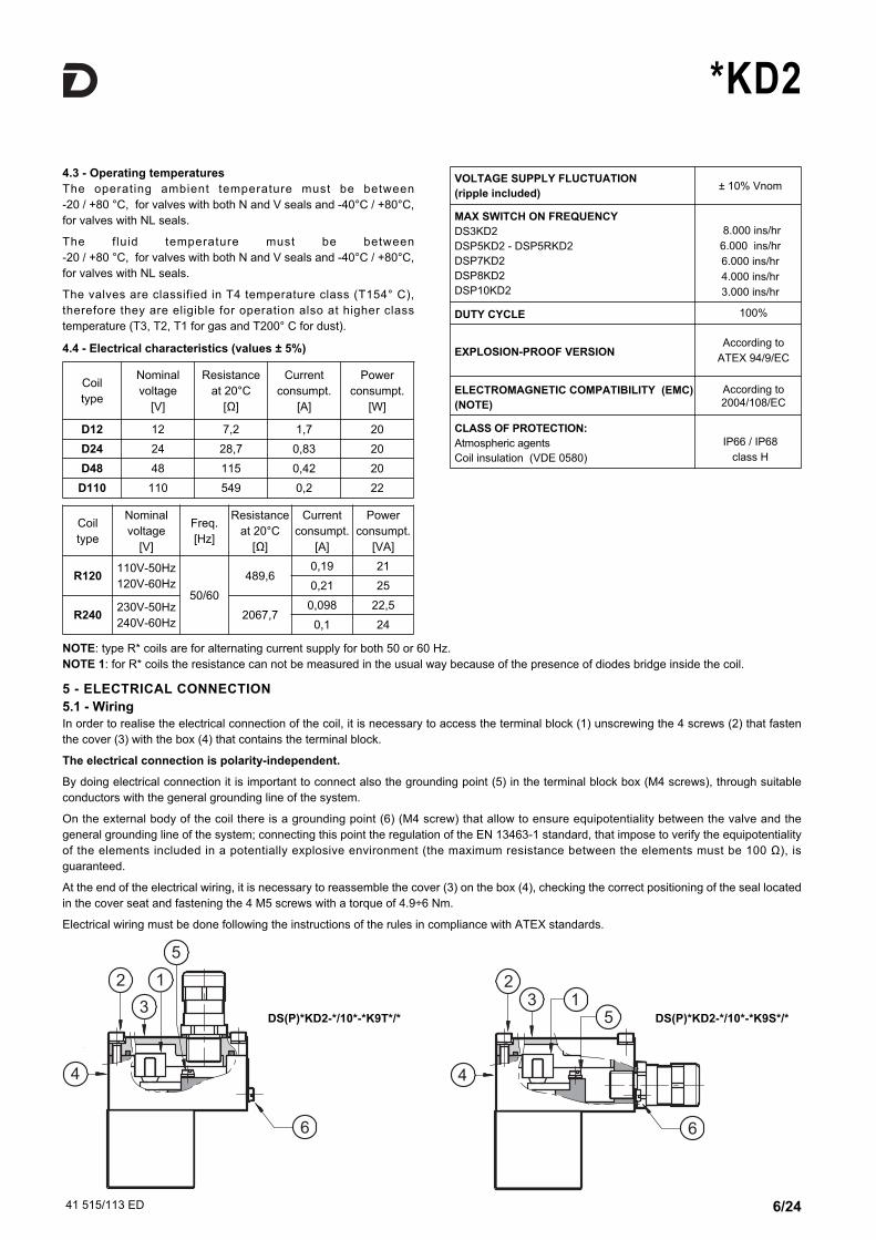
5 - ELECTRICAL CONNECTION
5.1 - Wiring
In order to realise the electrical connection of the coil, it is necessary to access the terminal block (1) unscrewing the 4 screws (2) that fasten
the cover (3) with the box (4) that contains the terminal block.
The electrical connection is polarity-independent.
By doing electrical connection it is important to connect also the grounding point (5) in the terminal block box (M4 screws), through suitable
conductors with the general grounding line of the system.
On the external body of the coil there is a grounding point (6) (M4 screw) that allow to ensure equipotentiality between the valve and the
general grounding line of the system; connecting this point the regulation of the EN 13463-1 standard, that impose to verify the equipotentiality
of the elements included in a potentially explosive environment (the maximum resistance between the elements must be 100 Ω), is
guaranteed.
At the end of the electrical wiring, it is necessary to reassemble the cover (3) on the box (4), checking the correct positioning of the seal located
in the cover seat and fastening the 4 M5 screws with a torque of 4.9÷6 Nm.
Electrical wiring must be done following the instructions of the rules in compliance with ATEX standards.
4.3 - Operating temperatures
The operating ambient temperature must be between
-20 / +80 °C, for valves with both N and V seals and -40°C / +80°C,
for valves with NL seals.
The fluid temperature must be between
-20 / +80 °C, for valves with both N and V seals and -40°C / +80°C,
for valves with NL seals.
The valves are classified in T4 temperature class (T154° C),
therefore they are eligible for operation also at higher class
temperature (T3, T2, T1 for gas and T200° C for dust).
Coil
type
Nominal
voltage
[V]
Resistance
at 20°C
[Ω]
Current
consumpt.
[A]
Power
consumpt.
[W]
D12 12 7,2 1,7 20
D24 24 28,7 0,83 20
D48 48 115 0,42 20
D110 110 549 0,2 22
NOTE: type R* coils are for alternating current supply for both 50 or 60 Hz.
NOTE 1: for R* coils the resistance can not be measured in the usual way because of the presence of diodes bridge inside the coil.
VOLTAGE SUPPLY FLUCTUATION
(ripple included)± 10% Vnom
MAX SWITCH ON FREQUENCY
DS3KD2
DSP5KD2 - DSP5RKD2
DSP7KD2
DSP8KD2
DSP10KD2
8.000 ins/hr
6.000 ins/hr
6.000 ins/hr
4.000 ins/hr
3.000 ins/hr
DUTY CYCLE 100%
EXPLOSION-PROOF VERSIONAccording to
ATEX 94/9/EC
ELECTROMAGNETIC COMPATIBILITY (EMC)
(NOTE)
According to
2004/108/EC
CLASS OF PROTECTION:
Atmospheric agents
Coil insulation (VDE 0580)
IP66 / IP68
class H
4.4 - Electrical characteristics (values ± 5%)
Coil
type
Nominal
voltage
[V]
Freq.
[Hz]
Resistance
at 20°C
[Ω]
Current
consumpt.
[A]
Power
consumpt.
[VA]
R120110V-50Hz
120V-60Hz50/60
489,60,19 21
0,21 25
R240230V-50Hz
240V-60Hz2067,7
0,098 22,5
0,1 24
DS(P)*KD2-*/10*-*K9T*/* DS(P)*KD2-*/10*-*K9S*/*
41 515/113 ED 7/24
*KD2
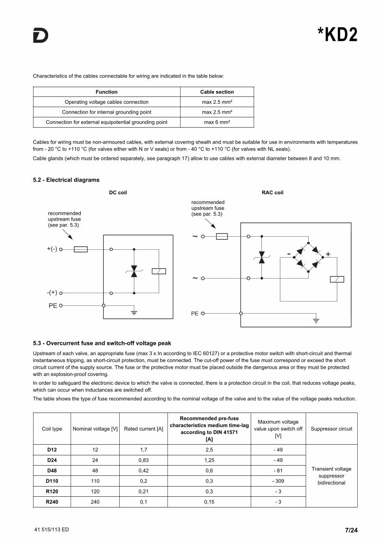
5.2 - Electrical diagrams
5.3 - Overcurrent fuse and switch-off voltage peak
Upstream of each valve, an appropriate fuse (max 3 x In according to IEC 60127) or a protective motor switch with short-circuit and thermal
instantaneous tripping, as short-circuit protection, must be connected. The cut-off power of the fuse must correspond or exceed the short
circuit current of the supply source. The fuse or the protective motor must be placed outside the dangerous area or they must be protected
with an explosion-proof covering.
In order to safeguard the electronic device to which the valve is connected, there is a protection circuit in the coil, that reduces voltage peaks,
which can occur when inductances are switched off.
The table shows the type of fuse recommended according to the nominal voltage of the valve and to the value of the voltage peaks reduction.
Characteristics of the cables connectable for wiring are indicated in the table below:
Cables for wiring must be non-armoured cables, with external covering sheath and must be suitable for use in environments with temperatures
from - 20 °C to +110 °C (for valves either with N or V seals) or from - 40 °C to +110 °C (for valves with NL seals).
Cable glands (which must be ordered separately, see paragraph 17) allow to use cables with external diameter between 8 and 10 mm.
Function Cable section
Operating voltage cables connection max 2.5 mm²
Connection for internal grounding point max 2.5 mm²
Connection for external equipotential grounding point max 6 mm²
Coil type Nominal voltage [V] Rated current [A]
Recommended pre-fuse
characteristics medium time-lag
according to DIN 41571
[A]
Maximum voltage
value upon switch off
[V]
Suppressor circuit
D12 12 1,7 2,5 - 49
Transient voltage
suppressor
bidirectional
D24 24 0,83 1,25 - 49
D48 48 0,42 0,6 - 81
D110 110 0,2 0,3 - 309
R120 120 0,21 0,3 - 3
R240 240 0,1 0,15 - 3
DC coil RAC coil
recommendedupstream fuse(see par. 5.3)
recommendedupstream fuse(see par. 5.3)

41 515/113 ED 8/24
*KD2
6.1 - Identification code
Size:
5 = CETOP P055R = ISO 4401-05 (CETOP R05)7 = ISO 4401-07 (CETOP 07)8 = ISO 4401-08 (CETOP 08)
10 = ISO 4401-10 (CETOP 10)
Pilot operateddirectional valve
Spool type (see par. 6.2)
S* TA TB RK
SA* TA02 TB02
SB*
Series No.: (the overall and mounting dimensionsremain unchanged from 10 to 19)
Drainage:
I = InternalE = External
Piloting:
I = internal (not available for spools S2 - S4 - TA02 - TB02- S*2 - S*4. If interal piloting should be necessary, choose piloting type C)
E = externalC = internal piloting with backpressure valve
(available on DSP7 and DSP8)Z = internal piloting with 30 bar fixed adjustment pressure reducing valve
D S P KD2 10 / /- / - /
Coil electrical connection:
electrical connection byterminal block
K9
6 - IDENTIFICATION OF PILOT OPERATED SOLENOID VALVES DSP*KD2
Options:
C = main spool stroke control
D = main spool shifting speed control
P08 = Subplate with restrictor Ø 0,8 on port Pplaced under the solenoid valve - for valvesDSP5 - DSP5R - DSP7 - DSP8
P15 = subplate with restrictor Ø 1,5 on port Pplaced under the solenoid valve - only for valvesDSP10
Explosion-proof version, according to ATEX - II 2GD for gas orfor dust (protection type of the coil: “d”)
Power supply:
D12 = 12 VD24 = 24 VD48 = 48 VD110 = 110 V
R120 = 120 VR240 = 240 V @ rectified current (RAC)
Connection type for cable gland
Available for upper connection:T01 = M20x1.5 - ISO 261T02 = Gk 1/2 - UNI EN 10226-2T03 = 1/2” NPT - ANSI B1.20.1(ex ANSI B2.1)
Available for side connection:S04 = M16x1.5 - ISO 261
(only for power supply D24)
S01 = M20x1.5 - ISO 261(available upon request only)
It is available, upon request, except for DSP5RKD2 and DSP10KD2 valve, the version suitable for an operating pressure value of
420 bar on ports P - A - B. For this version the maximum pressure values on port T with external drainage and the piloting
pressure can be equal to 350 bar. The maximum pressure on port T with internal drainage is 140 bar. Add the suffix H to request
this version (ex. DSP5HKD2).
Seals:
For temperature range -20 / +80 °C
N = NBR seals for mineral oil (standard)
V = FPM seals for special fluids
For temperature range -40 / +80 °C
NL = seal for low temperatures (for mineral oil)
Manual override:CM = manual override, bootprotected (standard forboth N and V seals - notavailable for NL seals)CB = blind ring nut(standard for NL seals -available upon request forboth N and V seals)For dimension details of CBversions, see paragraph 16
@ continuous current (DC)
Option: surfacetreatment notstandard. Omit ifnot required (seeNOTE 1)
NOTE 1: the valve is supplied with standard surface treatment of
phosphating black for the main body and zinc-nickel for the pilot body.
Upon request we can supply these valves completely with zinc-nickel
surface treatment; for this option add the suffix /W7 at the end of the
identification code.
41 515/113 ED 9/24
*KD2
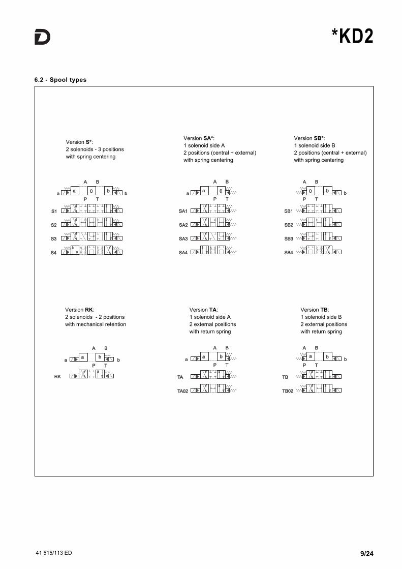
6.2 - Spool types
Version S*:
2 solenoids - 3 positions
with spring centering
Version TA:
1 solenoid side A
2 external positions
with return spring
Version TB:
1 solenoid side B
2 external positions
with return spring
Version RK:
2 solenoids - 2 positions
with mechanical retention
Version SA*:
1 solenoid side A
2 positions (central + external)
with spring centering
Version SB*:
1 solenoid side B
2 positions (central + external)
with spring centering

41 515/113 ED 10/24
*KD2
7.1 - Pressure drops ∆p-Q (values obtained with viscosity 36 cSt at 50 °C)
7 - CHARACTERISTIC CURVES AND PERFORMANCES OF PILOT OPERATED SOLENOID VALVES
SPOOL
FLOW DIRECTION
P→A P→B A→T B→T
CURVES ON GRAPH
S1, SA1, SB1 4 4 1 1
S2, SA2, SB2 3 3 1 2
S3, SA3, SB3 4 4 1 1
S4, SA4, SB4 5 5 2 3
TA, TB 4 4 1 1
TA02, TB02 3 3 1 1
RK 4 4 1 1
PRESSURE DROPS WITH VALVE IN ENERGIZED POSITION
PRESSURE DROPS WITH VALVE IN DE-ENERGIZED POSITION
SPOOL
FLOW DIRECTION
P→A P→B A→T B→T P→T
CURVES ON GRAPH
S2, SA2, SB2 - - - - 5
S3, SA3, SB3 - - 4 4 -
S4, SA4, SB4 - - - - 5
SPOOL
FLOW DIRECTION
P→A P→B A→T B→T
CURVES ON GRAPH
S1, SA1, SB1 1 1 3 4
S2, SA2, SB2 1 1 4 4
S3, SA3, SB3 1 1 4 4
S4, SA4, SB4 2 2 4 5
TA, TB 1 1 3 4
TA02, TB02 1 1 4 4
RK 1 1 3 4
PRESSURE DROPS WITH VALVE IN ENERGIZED POSITION
PRESSURE DROPS WITH VALVE IN DE-ENERGIZED POSITION
SPOOL
FLOW DIRECTION
P→A P→B A→T B→T P→T
CURVES ON GRAPH
S2, SA2, SB2 - - - - 2
S3, SA3, SB3 - - 4 4 -
S4, SA4, SB4 - - - - 4
DSP5KD2 - DSP5RKD2
DSP7KD2

41 515/113 ED 11/24
*KD2
DSP8KD2
SPOOL
FLOW DIRECTION
P→A P→B A→T B→T
CURVES ON GRAPH
S1, SA1, SB1 2 2 3 3
S2, SA2, SB2 1 1 2 1
S3, SA3, SB3 2 2 2 1
S4, SA4, SB4 4 4 3 5
TA, TB 2 2 3 3
TA02, TB02 2 2 3 3
RK 2 2 3 3
PRESSURE DROPS WITH VALVE IN ENERGIZED POSITION
PRESSURE DROPS WITH VALVE IN DE-ENERGIZED POSITION
SPOOL
FLOW DIRECTION
P→A P→B A→T B→T P→T
CURVES ON GRAPH
S2, SA2, SB2 - - - - 4
S3, SA3, SB3 - - 4 4 -
S4, SA4, SB4 - - - - 6
SPOOL
FLOW DIRECTION
P→A P→B A→T B→T
CURVES ON GRAPH
S1, SA1, SB1 1 1 1 1
S2, SA2, SB2 2 2 2 2
S3, SA3, SB3 1 1 4 4
S4, SA4, SB4 2 2 2 2
TA, TB 1 1 1 1
TA02, TB02 1 1 1 1
RK 1 1 1 1
PRESSURE DROPS WITH VALVE IN ENERGIZED POSITION
PRESSURE DROPS WITH VALVE IN DE-ENERGIZED POSITION
SPOOL
FLOW DIRECTION
P→A P→B A→T B→T P→T
CURVES ON GRAPH
S2, SA2, SB2 - - - - 3
S3, SA3, SB3 - - 4 4 -
S4, SA4, SB4 - - - - 4
DSP10KD2

41 515/113 ED 12/24
*KD2
7.2 - Performance limits
The values indicated refer to a solenoid valve working with piloting
pressure of 100 bar, with mineral oil at a temperature of 50°C, at
viscosity of 36 cSt and with PA and BT connections.
The energizing and de-energizing times are obtained at the
pressure variation which occurs on the lines.
TIMES (± 10%)
[ms]
ENERGIZING DE- ENERGIZING
DC - RAC DC RAC
DSP5KD2 - DSP5RKD2 70 60 160
DSP7KD2 80 70 170
DSP8KD2 90 70 170
DSP10KD2 120 90 190
7.3 - Switching times
MAXIMUM FLOW RATES DSP5KD2
DSP5RKD2DSP7KD2 DSP8KD2 DSP10KD2
Spool typePRESSURES
at 210 bar at 320 bar at 210 bar at 350 bar at 210 bar at 350 bar at 210 bar at 350 bar
S4 - SA4 - SB4[l/min]
120 100 200 150 500 450 750 (NOTE) 600 (NOTE)
Other spools 150 120 300 300 600 500 900 700
NOTE 1: minimum piloting pressure can be the lower range value at low flows rates, but with higher flow rates the higher value is needed.
NOTE 2: if the valve operates with higher pressures it is necessary to use the version with external pilot and reduced pressure. Otherwise, the
valve with internal pilot and pressure reducing valve with 30 bar fixed adjustment can be ordered. Add the letter Z to the identification code to
order this option (see par. 6.1). Consider that, by adding the pressure reducing valve, the overall dimensions increase 40 mm in height.
NOTE: for the DSP10KD2 valve these values are the same for S2 - SA2 - SB2 spools.
PRESSURESDSP5KD2
DSP5RKD2DSP7KD2 DSP8KD2 DSP10KD2
Max pressure in P, A, B ports 320 350 350 350
Max pressure in T line with internal drainage 140 140 140 140
Max pressure in T line with external drainage 210 210 210 210
Min piloting pressure NOTE 1 5 ÷ 10 5 ÷ 12 7 ÷ 14 6 ÷ 12
Max piloting pressure NOTE 2 210 210 210 210

41 515/113 ED 13/24
*KD2
X: plug M5x6 for external pilot
Y: plug M5x6 for external drain
X: plug M6x8 for external pilot
Y: plug M6x8 for external drain
DSP8KD2
DSP7KD2
T
DSP5KD2DSP5RKD2
8 - PILOTING AND DRAINAGEDSP*KD2 valves are available with piloting and drainage, both
internal and external.
The version with external drainage allows for a higher back
pressure on the outlet.
P
X: plug M6x8 for external pilot
Y: plug M6x8 for external drain
X: plug M6x8 for external pilot
Y: plug M6x8 for external drain
DSP10KD2
TYPE OF VALVEPlug assembly
X Y
IEINTERNAL PILOT ANDEXTERNAL DRAIN
NO YES
IIINTERNAL PILOT ANDINTERNAL DRAIN
NO NO
EEEXTERNAL PILOT ANDEXTERNAL DRAIN
YES YES
EIEXTERNAL PILOT ANDINTERNAL DRAIN
YES NO

41 515/113 ED 14/24
*KD2
pilot always internal
Y: plug M6x8 for external drain
8.1 - Backpressure valve incorporated on line P (C option)
DSP7KD2 and DSP8KD2 valves are available upon request with backpressure valve incorporated on line P.
This is necessary to obtain the piloting pressure when the control valve, in rest position, has the line P
connected to the T port (spools S2 - S4 - S*2 - S*4 - TA02 - TB02). The cracking pressure is of 5 bar with a
minimum flow rate of 15 l/min.
In the C version the piloting is always internal.
NOTE: the backpressure valve can’t be used as check valve because it doesn’t assure the seal.
Add C to the identification code for this request (see paragraph 6.1).
For DSP7KD2 only, the backpressure valve can be also delivered separately and it can be easily mounted on line P of the main control valve.
Ask for code 0266577 to order the backpressure valve.
The curve refers to the pressure drop (body part only) with
backpressure valve energized to which the pressure drop of
the reference spool must be added (see paragraph 7.1).
DSP8KD2DSP7KD2
41 515/113 ED 15/24
*KD2
DSP*KD2-*/D
DSP*KD2-*/P*
DSP*KD2-*/C
dimensions in mm
dimensions in mm
dimensions in mm
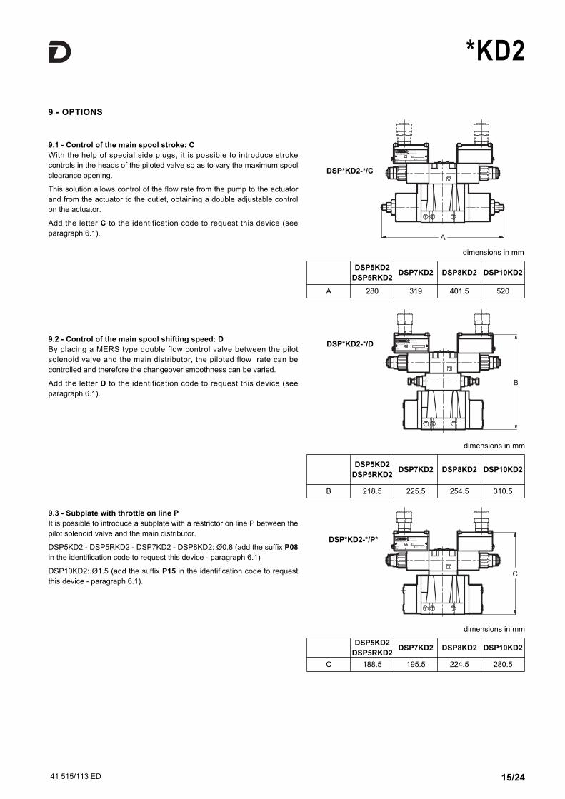
9 - OPTIONS
9.1 - Control of the main spool stroke: C
With the help of special side plugs, it is possible to introduce stroke
controls in the heads of the piloted valve so as to vary the maximum spool
clearance opening.
This solution allows control of the flow rate from the pump to the actuator
and from the actuator to the outlet, obtaining a double adjustable control
on the actuator.
Add the letter C to the identification code to request this device (see
paragraph 6.1).
9.2 - Control of the main spool shifting speed: D
By placing a MERS type double flow control valve between the pilot
solenoid valve and the main distributor, the piloted flow rate can be
controlled and therefore the changeover smoothness can be varied.
Add the letter D to the identification code to request this device (see
paragraph 6.1).
9.3 - Subplate with throttle on line P
It is possible to introduce a subplate with a restrictor on line P between the
pilot solenoid valve and the main distributor.
DSP5KD2 - DSP5RKD2 - DSP7KD2 - DSP8KD2: Ø0.8 (add the suffix P08
in the identification code to request this device - paragraph 6.1)
DSP10KD2: Ø1.5 (add the suffix P15 in the identification code to request
this device - paragraph 6.1).
DSP5KD2
DSP5RKD2DSP7KD2 DSP8KD2 DSP10KD2
A 280 319 401.5 520
DSP5KD2
DSP5RKD2DSP7KD2 DSP8KD2 DSP10KD2
B 218.5 225.5 254.5 310.5
DSP5KD2
DSP5RKD2DSP7KD2 DSP8KD2 DSP10KD2
C 188.5 195.5 224.5 280.5
41 515/113 ED 16/24
*KD2
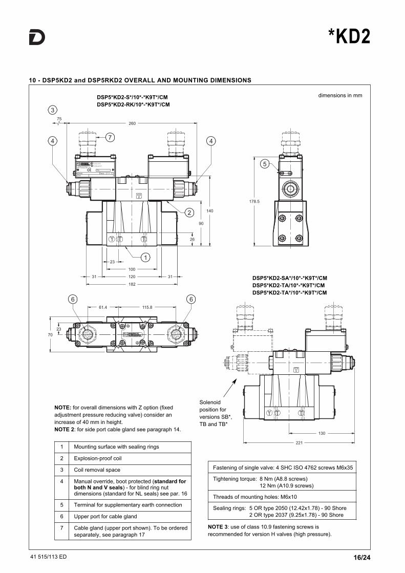
10 - DSP5KD2 and DSP5RKD2 OVERALL AND MOUNTING DIMENSIONS
dimensions in mm
Fastening of single valve: 4 SHC ISO 4762 screws M6x35
Tightening torque: 8 Nm (A8.8 screws)
12 Nm (A10.9 screws)
Threads of mounting holes: M6x10
Sealing rings: 5 OR type 2050 (12.42x1.78) - 90 Shore
2 OR type 2037 (9.25x1.78) - 90 Shore
NOTE: for overall dimensions with Z option (fixed
adjustment pressure reducing valve) consider an
increase of 40 mm in height.
NOTE 2: for side port cable gland see paragraph 14.
1 Mounting surface with sealing rings
2 Explosion-proof coil
3 Coil removal space
4 Manual override, boot protected (standard forboth N and V seals) - for blind ring nutdimensions (standard for NL seals) see par. 16
5 Terminal for supplementary earth connection
6 Upper port for cable gland
7 Cable gland (upper port shown). To be ordered
separately, see paragraph 17
DSP5*KD2-S*/10*-*K9T*/CM
DSP5*KD2-RK/10*-*K9T*/CM
DSP5*KD2-SA*/10*-*K9T*/CM
DSP5*KD2-TA/10*-*K9T*/CM
DSP5*KD2-TA*/10*-*K9T*/CM
Solenoid
position for
versions SB*,
TB and TB*
NOTE 3: use of class 10.9 fastening screws is
recommended for version H valves (high pressure).
41 515/113 ED 17/24
*KD2
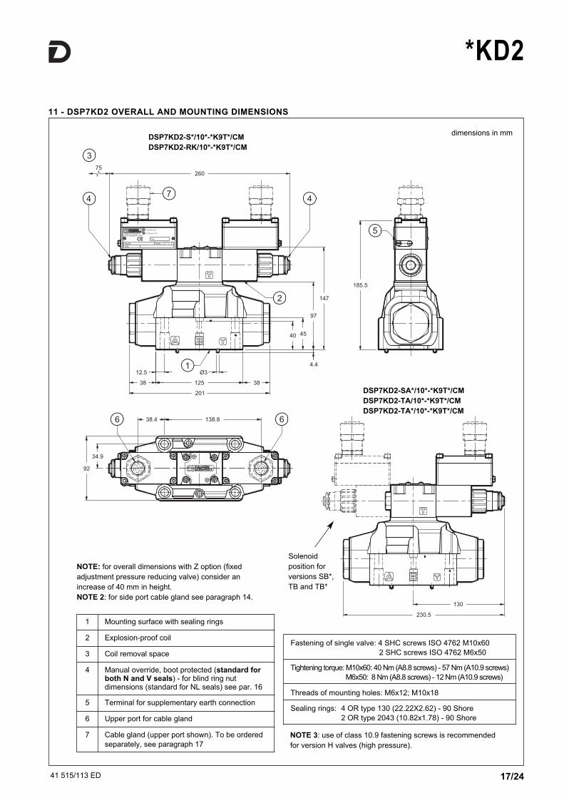
11 - DSP7KD2 OVERALL AND MOUNTING DIMENSIONS
dimensions in mm
NOTE: for overall dimensions with Z option (fixed
adjustment pressure reducing valve) consider an
increase of 40 mm in height.
NOTE 2: for side port cable gland see paragraph 14.
Fastening of single valve: 4 SHC screws ISO 4762 M10x60
2 SHC screws ISO 4762 M6x50
Tightening torque: M10x60: 40 Nm (A8.8 screws) - 57 Nm (A10.9 screws)
M6x50: 8 Nm (A8.8 screws) - 12 Nm (A10.9 screws)
Threads of mounting holes: M6x12; M10x18
Sealing rings: 4 OR type 130 (22.22X2.62) - 90 Shore
2 OR type 2043 (10.82x1.78) - 90 Shore
1 Mounting surface with sealing rings
2 Explosion-proof coil
3 Coil removal space
4 Manual override, boot protected (standard forboth N and V seals) - for blind ring nutdimensions (standard for NL seals) see par. 16
5 Terminal for supplementary earth connection
6 Upper port for cable gland
7 Cable gland (upper port shown). To be ordered
separately, see paragraph 17
DSP7KD2-S*/10*-*K9T*/CM
DSP7KD2-RK/10*-*K9T*/CM
DSP7KD2-SA*/10*-*K9T*/CM
DSP7KD2-TA/10*-*K9T*/CM
DSP7KD2-TA*/10*-*K9T*/CM
Solenoid
position for
versions SB*,
TB and TB*
NOTE 3: use of class 10.9 fastening screws is recommended
for version H valves (high pressure).

41 515/113 ED 18/24
*KD2
12 - DSP8KD2 OVERALL AND MOUNTING DIMENSIONS
dimensions in mm
NOTE: for overall dimensions with Z option (fixed
adjustment pressure reducing valve) consider an
increase of 40 mm in height.
NOTE 2: for side port cable gland see paragraph 14.
Fastening of single valve: 6 SHC ISO 4762 screws M12x60
Tightening torque: 69 Nm (A8.8 screws) - 97 Nm (A10.9 screws)
Threads of mounting holes: M12x20
Sealing rings: 4 OR type 3118 (29.82x2.62) - 90 Shore
2 OR type 3081 (20.24x2.62) - 90 Shore
1 Mounting surface with sealing rings
2 Explosion-proof coil
3 Coil removal space
4 Manual override, boot protected (standard forboth N and V seals) - for blind ring nutdimensions (standard for NL seals) see par. 16
5 Terminal for supplementary earth connection
6 Upper port for cable gland
7 Cable gland (upper port shown). To be ordered
separately, see paragraph 17
DSP8KD2-S*/10*-*K9T*/CM
DSP8KD2-RK/10*-*K9T*/CM
DSP5KD2-SA*/10*-*K9T*/CM
DSP5KD2-TA/10*-*K9T*/CM
DSP5KD2-TA*/10*-*K9T*/CM
Solenoid
position for
versions SB*,
TB and TB*
NOTE 3: use of class 10.9 fastening screws is
recommended for version H valves (high pressure).
41 515/113 ED 19/24
*KD2
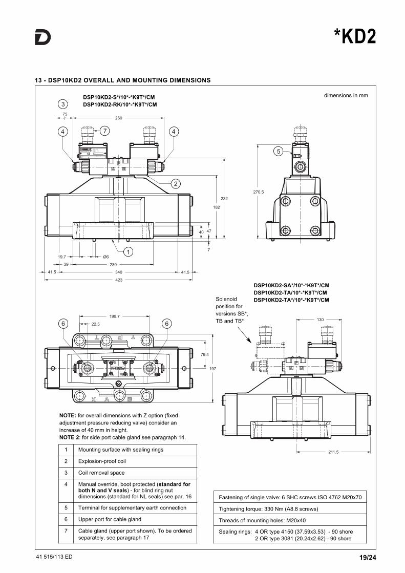
13 - DSP10KD2 OVERALL AND MOUNTING DIMENSIONS
dimensions in mm
NOTE: for overall dimensions with Z option (fixed
adjustment pressure reducing valve) consider an
increase of 40 mm in height.
NOTE 2: for side port cable gland see paragraph 14.
Fastening of single valve: 6 SHC screws ISO 4762 M20x70
Tightening torque: 330 Nm (A8.8 screws)
Threads of mounting holes: M20x40
Sealing rings: 4 OR type 4150 (37.59x3.53) - 90 shore
2 OR type 3081 (20.24x2.62) - 90 shore
1 Mounting surface with sealing rings
2 Explosion-proof coil
3 Coil removal space
4 Manual override, boot protected (standard forboth N and V seals) - for blind ring nutdimensions (standard for NL seals) see par. 16
5 Terminal for supplementary earth connection
6 Upper port for cable gland
7 Cable gland (upper port shown). To be ordered
separately, see paragraph 17
Solenoid
position for
versions SB*,
TB and TB*
DSP10KD2-S*/10*-*K9T*/CM
DSP10KD2-RK/10*-*K9T*/CM
DSP10KD2-SA*/10*-*K9T*/CM
DSP10KD2-TA/10*-*K9T*/CM
DSP10KD2-TA*/10*-*K9T*/CM
41 515/113 ED 20/24
*KD2
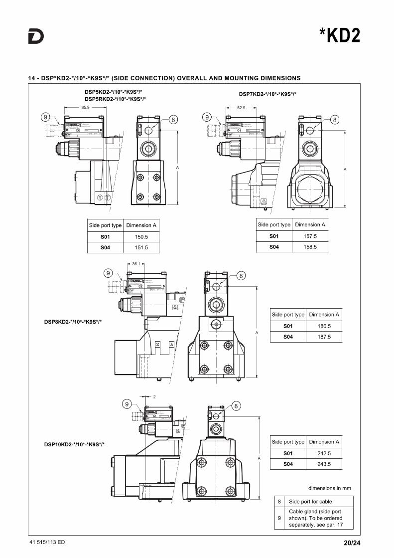
14 - DSP*KD2-*/10*-*K9S*/* (SIDE CONNECTION) OVERALL AND MOUNTING DIMENSIONS
DSP5KD2-*/10*-*K9S*/*
DSP5RKD2-*/10*-*K9S*/*DSP7KD2-*/10*-*K9S*/*
DSP8KD2-*/10*-*K9S*/*
DSP10KD2-*/10*-*K9S*/*
Side port type Dimension A
S01 150.5
S04 151.5
Side port type Dimension A
S01 157.5
S04 158.5
Side port type Dimension A
S01 186.5
S04 187.5
Side port type Dimension A
S01 242.5
S04 243.5
8 Side port for cable
9
Cable gland (side port
shown). To be ordered
separately, see par. 17
dimensions in mm
41 515/113 ED 21/24
*KD2
0.75
T
B31.75
P
A25.915.5
5.1
12.7
31
M5
Ø4
Ø7.5 (max)Ø7.5 (max)
21.5
30.2
40.5
33
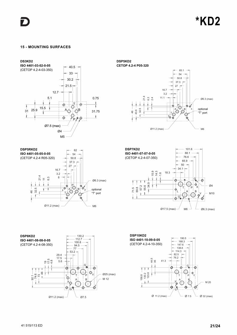
DS3KD2
ISO 4401-03-02-0-05
(CETOP 4.2-4-03-350)
Ø6.3 (max)
attacco "T"
M6
facoltativo
54
65.1
50.8
27
37.3
B
P
A
11.1
3.2
16.7
Ty
Ø11.2 (max)
x
46
43
.6
32
.5
21
.4
6.3
2.4
54
62
50.8
y
P
B
facoltativo
M6
attacco "T"
Ø6.3 (max)8
3.2
16.7
Tx A
Ø11.2 (max)
37.3
27
46 32
.5
21
.4
11 6.3
DSP5KD2
CETOP 4.2-4 P05-320
DSP5RKD2
ISO 4401-05-05-0-05
(CETOP 4.2-4 R05-320)
101.6
88.1
76.6
65.9
50
34.1
Y
Ø4
M10
Ø6.3 (max)
BA
P
L
T
G
M6
X
G
18.3
Ø17.5 (max)
71
.5
69
.8 57
.2
55
.6 34
.9
15
.9
14
.3
1.6
DSP7KD2
ISO 4401-07-07-0-05
(CETOP 4.2-4-07-350)
130.2112.7
G
Ø25 (max)
M 12
P
B
Y
Ø7.5
53.229.417.5
5.6
L
X
G
Ø11.2 (max)
A
T
7794.5100.8
92
.17
4.6
73 4
6
19
17
.54
.8
DSP8KD2
ISO 4401-08-08-0-05
(CETOP 4.2-4-08-350)
15 - MOUNTING SURFACES
190.5
168.3
Y
G
P
76.2
114.3
82.5
T
138.6
147.6
M 20
Ø 32 (max)Ø 7.5
G
XA B
41.3
Ø 11.2 (max)
15
8.8
13
0.2
12
3.8
44
.5
35
DSP10KD2
ISO 4401-10-09-0-05
(CETOP 4.2-4-10-350)
optional
“T” port
optional
“T” port
41 515/113 ED 22/24
*KD2
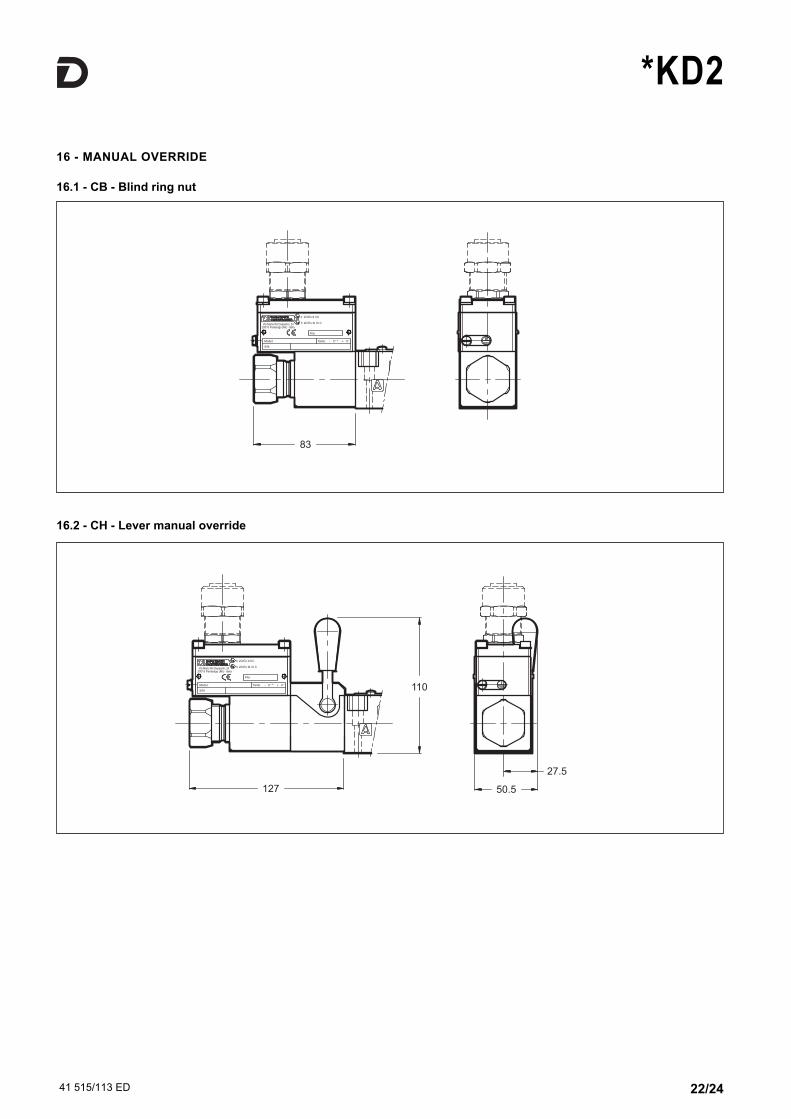
16 - MANUAL OVERRIDE
16.1 - CB - Blind ring nut
16.2 - CH - Lever manual override
41 515/113 ED 23/24
*KD2
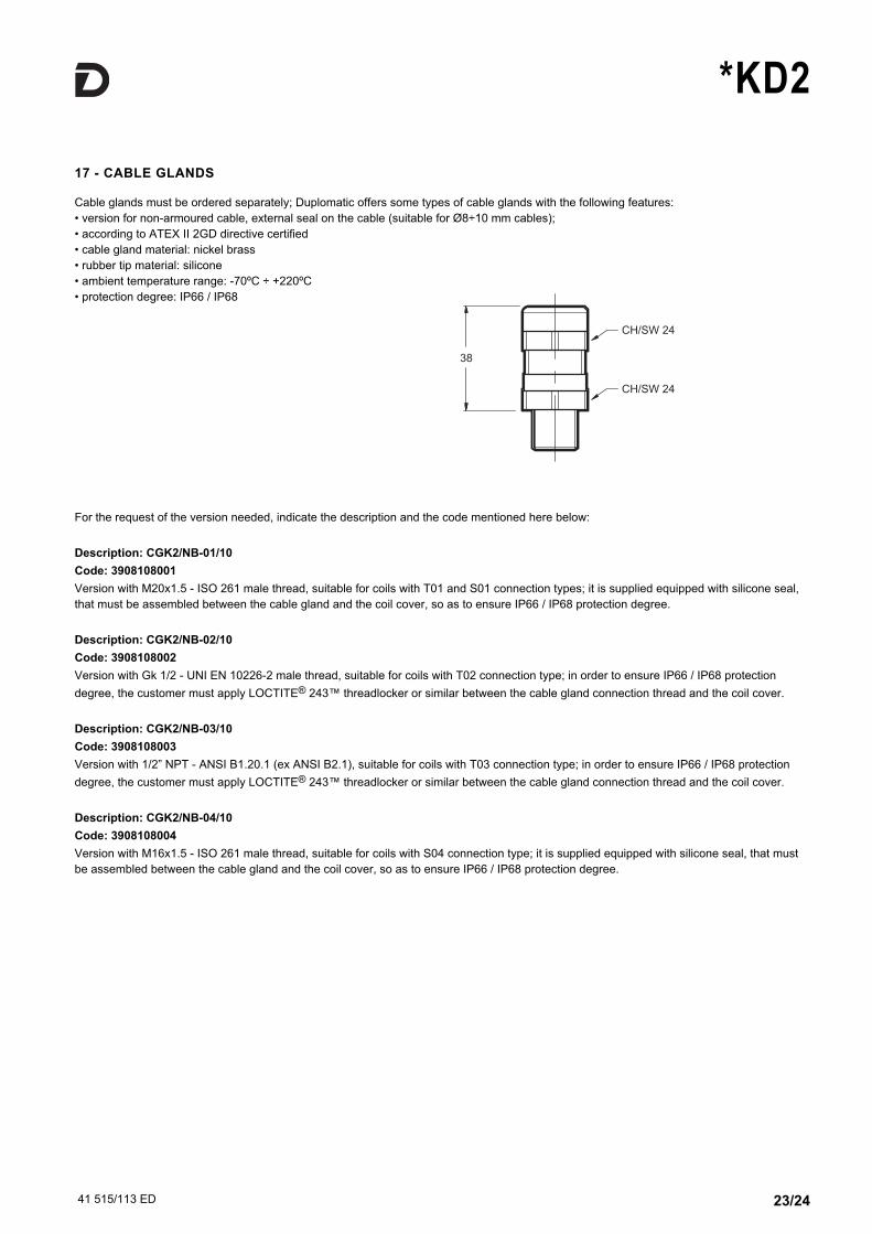
17 - CABLE GLANDS
Cable glands must be ordered separately; Duplomatic offers some types of cable glands with the following features:
• version for non-armoured cable, external seal on the cable (suitable for Ø8÷10 mm cables);
• according to ATEX II 2GD directive certified
• cable gland material: nickel brass
• rubber tip material: silicone
• ambient temperature range: -70ºC ÷ +220ºC
• protection degree: IP66 / IP68
For the request of the version needed, indicate the description and the code mentioned here below:
Description: CGK2/NB-01/10
Code: 3908108001
Version with M20x1.5 - ISO 261 male thread, suitable for coils with T01 and S01 connection types; it is supplied equipped with silicone seal,
that must be assembled between the cable gland and the coil cover, so as to ensure IP66 / IP68 protection degree.
Description: CGK2/NB-02/10
Code: 3908108002
Version with Gk 1/2 - UNI EN 10226-2 male thread, suitable for coils with T02 connection type; in order to ensure IP66 / IP68 protection
degree, the customer must apply LOCTITE® 243™ threadlocker or similar between the cable gland connection thread and the coil cover.
Description: CGK2/NB-03/10
Code: 3908108003
Version with 1/2” NPT - ANSI B1.20.1 (ex ANSI B2.1), suitable for coils with T03 connection type; in order to ensure IP66 / IP68 protection
degree, the customer must apply LOCTITE® 243™ threadlocker or similar between the cable gland connection thread and the coil cover.
Description: CGK2/NB-04/10
Code: 3908108004
Version with M16x1.5 - ISO 261 male thread, suitable for coils with S04 connection type; it is supplied equipped with silicone seal, that must
be assembled between the cable gland and the coil cover, so as to ensure IP66 / IP68 protection degree.
41 515/113 ED 24/24
! "# ! $$$%&'())'*'+,,#-%&'())'
*KD2
REPRODUCTION IS FORBIDDEN. THE COMPANY RESERVES THE RIGHT TO APPLY ANY MODIFICATIONS.
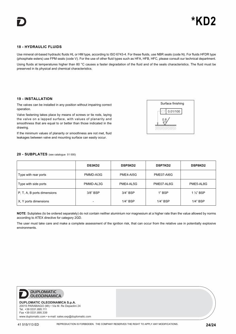
19 - INSTALLATION
The valves can be installed in any position without impairing correct
operation.
Valve fastening takes place by means of screws or tie rods, laying
the valve on a lapped surface, with values of planarity and
smoothness that are equal to or better than those indicated in the
drawing.
If the minimum values of planarity or smoothness are not met, fluid
leakages between valve and mounting surface can easily occur.
18 - HYDRAULIC FLUIDS
Use mineral oil-based hydraulic fluids HL or HM type, according to ISO 6743-4. For these fluids, use NBR seals (code N). For fluids HFDR type
(phosphate esters) use FPM seals (code V). For the use of other fluid types such as HFA, HFB, HFC, please consult our technical department.
Using fluids at temperatures higher than 80 °C causes a faster degradation of the fluid and of the seals characteristics. The fluid must be
preserved in its physical and chemical characteristics.
20 - SUBPLATES (see catalogue 51 000)
DS3KD2 DSP5KD2 DSP7KD2 DSP8KD2
Type with rear ports PMMD-AI3G PME4-AI5G PME07-AI6G
Type with side ports PMMD-AL3G PME4-AL5G PME07-AL6G PME5-AL8G
P, T, A, B ports dimensions
X, Y ports dimensions
3/8” BSP
-
3/4” BSP
1/4” BSP
1” BSP
1/4” BSP
1 ½” BSP
1/4” BSP
NOTE: Subplates (to be ordered separately) do not contain neither aluminium nor magnesium at a higher rate than the value allowed by norms
according to ATEX directive for category 2GD.
The user must take care and make a complete assessment of the ignition risk, that can occur from the relative use in potentially explosive
environments.
Surface finishing