4-unit hthp filter press with load cell option · 175-ml hthp test cells for simultaneous testing....
TRANSCRIPT
4-Unit HTHP Filter Press With Load Cell Option
#170-00-4S - 115 VAC #170-00-4S-230 - 230 VAC
#170-00-4S-LC Load Cell Option
Instruction Manual Updated 10/5/2015
Ver. 4.0OFI Testing Equipment, Inc.
11302 Steeplecrest Dr. · Houston, Texas · 77065 · U.S.A. Tele: 832.320.7300 · Fax: 713.880.9886 · www.ofite.com
©Copyright OFITE 2015

OFITE, 11302 Steeplecrest Dr., Houston, TX 77065 USA / Tel: 832-320-7300 / Fax: 713-880-9886 / www.ofite.com 1
Intro....................................................................................................... 2Specifications ...................................................................................... 2Components ........................................................................................ 2Safety .................................................................................................... 3Setup..................................................................................................... 4Operation.............................................................................................. 5Load Cell Option ................................................................................ 10
Software Setup ...............................................................................11
Calibration ...................................................................................... 14
Appendix ............................................................................................ 15Driver Install ................................................................................... 15
Warranty and Return Policy ............................................................. 18
Table ofContent

OFITE, 11302 Steeplecrest Dr., Houston, TX 77065 USA / Tel: 832-320-7300 / Fax: 713-880-9886 / www.ofite.com 2
The OFITE 4-Unit HTHP Filter Press Heat Jacket is designed to hold four, 175-mL HTHP test cells for simultaneous testing. Each cell has a separate temperature controller and two pressure regulators (drive pressure and back pressure) for independent testing.
Maximum Temperature: 425°F (218.3°C) Maximum Inlet Pressure: 3,000 PSI (20.7 MPa) Maximum Drive Pressure: 1,350 PSI (9.3 MPa) Maximum Back Pressure: 750 PSI (5.2 MPa) Power Requirements: 115 VAC or 230 VAC configurations available (power cord included) Cell Size: 175 mL (Cells not included)
Included: #120-05-005 Fuse Holder (230 Volt) #120-05-005-1 Fuse Holder (115 Volt) #120-70-1-052 Hose, Stainless Steel, 18" #130-81-015 Relief Valve #130-81-028 Regulator #152-37 AC Power Cord (115 Volt) #152-38 AC Power Cord (230 Volt) #153-14 Graduated Cylinder, 50 mL × 1 mL, Glass #170-06-1 Back Pressure Receiver #170-07 O-ring for Receiver Body#170-19 Filter Paper, Specially Hardened for Filter Presses, 2.5"
(6.35 cm) Diameter, Box of 100#170-20 Manifold Block #170-93 Wrench for Valve Stem #171-45-7 Thermocouple #171-23-1 Safety Pin with Lanyard #174-03 Temperature Controller
Test Cells: Test cells are not included with the instrument. The following 175 mL cells are available. #170-12-1 Test Cell for Filter Paper, 175 mL, Single Cap #170-45 Test Cell with Cement Screens, 175 mL, Double Cap #170-48 Test Cell for Ceramic Disks, 175 mL, Single Cap #170-46 Test Cell for Ceramic Disks, 175 mL, Double Cap
Accessories: #170-13-3 O-ring for Test Cell, Viton®/Fluorocarbon (FKM) #170-16 Valve Stem #170-17 O-ring for Valve Stem, Viton®/Fluorocarbon (FKM) #170-26-1 Locking Screw, Hardened Alloy Steel
Intro
Specifications
Components

OFITE, 11302 Steeplecrest Dr., Houston, TX 77065 USA / Tel: 832-320-7300 / Fax: 713-880-9886 / www.ofite.com 3
Safety
Optional: Load Cell Accessory Kit: #170-00-4S-LC Load Cell Assembly; Qty: 4 #170-00-4S-013 4-Port USB Hub
Nitrogen must be supplied in an approved Nitrogen Gas Cylinder and secured to meet safety standards.
Due to the high temperatures and pressures involved in this test, extreme care must be exercised at all times. All safety precautions must be met, especially in the cell breakdown procedure after the filtration procedure has been completed.

OFITE, 11302 Steeplecrest Dr., Houston, TX 77065 USA / Tel: 832-320-7300 / Fax: 713-880-9886 / www.ofite.com 4
Setup 1. Remove the instrument from the crate and place it on a flat, stable surface.
2. Turn off the Nitrogen valve (horizontal). Turn off both Main Power switches and all four Heat switches. Make sure all regulators are backed off completely. Turn them completely counterclockwise.
3. Connect a Nitrogen source to the back of the unit. The inlet connector is ¼" NPT.
4. On the back of the unit is a power inlet configured for 115 VAC or 230 VAC. Plug the supplied power cord into an appropriate power source.
- #170-00-4S: 115 VAC, 50/60 Hz - #170-00-4S-1: 230 VAC, 50/60 Hz

OFITE, 11302 Steeplecrest Dr., Houston, TX 77065 USA / Tel: 832-320-7300 / Fax: 713-880-9886 / www.ofite.com 5
Operation Although all four test cells share a single Nitrogen source, they each have two regulators for adjusting drive pressure and back pressure. Each cell also has a separate temperature controller.
There are two main power switches on the front of the instrument. The switch on the left controls power to the two cells on the left. The switch on the right controls power to the two cells on the right.
The valve on the front controls the flow of Nitrogen pressure to the regulators. When the valve is horizontal, the pressure is turned on. When it is vertical, the pressure is turned off.
1. Before starting a test, make sure the Nitrogen valve is off (vertical). Turn off both Main Power switches and all four Heat switches. Make sure all regulators are backed off completely. Turn them completely counterclockwise.
2. Turn the Main Power switches on.
3. Press the up and down arrows on the temperature controller to set the desired test temperature.
4. Turn the Heat switch on. Each cell has a separate Heat switch.
The light next to the cell will turn on when the heaters are engaged.
5. Be sure all of the o-rings are in good working condition (pliable with no nicks or cuts, etc.), and are not damaged during the assembly procedures. Place a thin film of silicone grease on all o-rings.
Nitril-NBR (Buna N) o-rings (#170-13) are recommended for tests up to 250°F (121°C). For tests up to 400°F (204°C), Fluorocarbon/FKM (Viton®) o-rings (#170-13-3) are recommended. For tests up to 500°F (260°C), Perfluorocarbon (FFKM) o-rings are recommended. Also, for tests with water-based fluids containing no hydrocarbons, Ethylene propylene (EPM/EPDM) o-rings may be used up to 400°F (204°C).
Heater Indicator
Thermocouple Hole
Power to Left Side Power to Right SideNitrogen Valve

OFITE, 11302 Steeplecrest Dr., Houston, TX 77065 USA / Tel: 832-320-7300 / Fax: 713-880-9886 / www.ofite.com 6
6. Screw a valve stem into the test cell on the side opposite the cell cap. Tighten the valve stem completely.
7. Prepare the sample according to API specifications.
8. Carefully pour the sample into the cell. Do not fill the cell closer than 0.5" (13 mm) from the o-ring groove to allow for heat expansion of the fluid. Be careful not to spill fluid in the o-ring groove.
9. Place an o-ring in the o-ring groove inside the cell. Place another o-ring in the recess in the cell cap.
10. Place a circle of filter paper on top of the cell o-ring and slowly push the cell cap into the test cell. Make sure the arrow on the cell cap lines up with the arrow on the cell body. Tighten the cap locking screws.
If the cap locking screw seats are oval shaped and no longer round, there is a possibility of stress failure and the cap should be replaced.
11. Screw another valve stem into the cell cap and tighten it completely. The cell is now completely sealed.
12. Place the cell in the heating jacket with the outlet or filter side of the cell pointed down. Rotate the cell in the heating jacket so that the pin in the bottom of the heating well seats into the hole in the bottom of the cell. This will anchor the cell inside the well and prevent the cell from rotating as the valve stems are opened and closed.
13. Transfer the thermocouple from the heating jacket to the thermometer well within the cell.
Locking Screws, Qty. 6 (#170-26-1)
Valve Stem, Qty. 2 (#170-16)
Cell Cap With Screen (#170-14)
Allen Wrench 5/32" (#170-27)
Valve Stem O-ring, Qty. 4 (#170-17)
Cell Cap O-ring (#170-13-3)
Cell Body (#170-12-1)

OFITE, 11302 Steeplecrest Dr., Houston, TX 77065 USA / Tel: 832-320-7300 / Fax: 713-880-9886 / www.ofite.com 7
14. Connect the manifold block to the top valve stem and lock it in place with the retainer pin. Place the back pressure receiver on the bottom valve stem and lock it in place with the other retainer pin. Make sure both relief valves and both valve stems are closed.
Relief Valve (#170-32)
Manifold Block (#170-20)
Valve Stem (#170-16)
Retainer Pin (#171-23-1)
Retainer Pin (#171-23-1)
Valve Stem (#170-16)
Receiver Body (#170-06-1)
Relief Valve (#120-85-017)

OFITE, 11302 Steeplecrest Dr., Houston, TX 77065 USA / Tel: 832-320-7300 / Fax: 713-880-9886 / www.ofite.com 8
15. Turn the Nitrogen valve on.
16. Set the top and bottom regulators to the recommended back pressure for your test.
The upper and lower limits of the test pressure differential are determined by the test temperature. As this temperature exceeds 212°F (100°C), the back pressure must be increased in order to prevent vaporization of the filtrate. The 500 PSI differential pressure must be maintained, so the top pressure will have to be increased accordingly. The table below shows the pressures recommended for various test temperatures.
Recommended Minimum Back PressureTest Temperature Vapor Pressure Minimum Back Pressure°F °C PSI kPa PSI kPa
212 100 14.7 101 100 690250 121 30 207 100 690300 149 67 462 100 690350 177 135 932 160 1,104400* 204 247 1,704 275 1,898450* 232 422 2,912 450 3,105500* 260 680 4,692 700 4,830
*For tests above 400°F, use Perfluorocarbon (FFKM) o-rings
17. Open the top valve stem by turning it one quarter turn. This will add pressure to the test cell. Maintain this pressure until the sample temperature stabilizes. The heating time of the sample should never exceed one hour.
18. When the fluid sample reaches the desired test temperature, increase the pressure on the top pressure unit to 500 PSI (3,448 kPa) more than the back pressure. Open the bottom valve stem to initiate filtration.
19. Collect the filtrate for 30 minutes. If the back pressure rises above the initial setting during the test, cautiously reduce the pressure by opening the valve on the receiver and drawing off some of the filtrate into the graduated cylinder.
20. At the end of the test, close (tighten) the top and bottom valve stems. This will seal the cell.
Failure to close the valve stems before releasing pressure (step 22) will damage a regulator by drawing fluid into it.
21. Turn off the heat switch and set the temperature controller to the lowest setting.

OFITE, 11302 Steeplecrest Dr., Houston, TX 77065 USA / Tel: 832-320-7300 / Fax: 713-880-9886 / www.ofite.com 9
22. Slowly turn the regulators counterclockwise to close off the flow of pressurized gas.
23. Open the outlet valve on the back pressure receiver to collect all of the filtrate in the graduated cylinder. Open the relief valve on the top of the cell to release pressure from the lines.
24. Remove the top and bottom retaining pins and remove the manifold block and the back pressure receiver. Drain any residual filtrate collected in the receiver into the graduated cylinder.
25. Remove the cell from the heating jacket after once again checking that the cell valve stems are tightly closed. Allow it to cool to room temperature or quick cool the cell by immersion in cool water.
Pressure inside the sample cell will still be approximately 500 PSI (3,450 kPa). Keep the cell upright and cool it to room temperature before disassembling. The cell must be cool for at least one hour at room temperature or at least 10 minutes in cool water before loosening the cap locking screws and removing the cell cap.
26. Correct the total filtrate volume collected to a standard filtration test area of 7.1 in2 (45.8 cm2) by doubling the filtrate volume collected in 30 minutes. Record this total filtrate volume (doubled), temperature, pressure, and time.
27. Using extreme care to save the filter paper and deposited cake, place the cooled cell upright with the outlet (cap side) or filter side down. Open (loosen) the inlet valve stem to bleed off pressure from the cell body.
Pressure cannot be relieved from the cell by opening the outlet valve stem as the filter cake will seal off the cell. It is a good idea to open the valve stem with the cell inside a sink or with a rag over the valve stem in order to catch any liquid that might be ejected.
28. Loosen, but do not remove, the six cap locking screws, and separate the cap from the cell with a slight rocking motion. Discard the fluid inside the cell and retrieve the filter cake.
29. Wash the filter cake on the paper with a gentle stream of water. Measure and report the thickness of the filter cake to the nearest 1/32" (0.8 mm).
30. Clean and dry the apparatus thoroughly after each use. Inspect and, if necessary, replace all of the o-rings.
31. After all testing is complete, turn off all four heat switches, set the temperature controllers to 0, back off the regulators (counterclockwise), and turn both Main Power switches off.

OFITE, 11302 Steeplecrest Dr., Houston, TX 77065 USA / Tel: 832-320-7300 / Fax: 713-880-9886 / www.ofite.com 10
Load Cell Option
The Load Cell option (#170-00-4S-LC) consists of four low profile precision scales designed to take more accurate measurements of fluid dispensed from filtration tests. Information from each load cell is sent to the user’s computer via USB connections.
1. Set up Load Cells in their designated positions on the base of the 4-unit filter press making sure that the corners of the base plates meet with their correlated posts.
Place load cells 1 and 2 to the left of their designated support rods and load cells 3 and 4 to the right of their designated support rods.
Cell 1 Cell 2 Cell 3 Cell 4
2. Run the USB cables off to the side along the back panel.
3. Plug the USB cables into the (#170-00-4S-013) 4-Port Hub.
Support Rods

OFITE, 11302 Steeplecrest Dr., Houston, TX 77065 USA / Tel: 832-320-7300 / Fax: 713-880-9886 / www.ofite.com 11
Load Cell Option
Software Setup
With the load cell option comes a software program which allows the user to log and archive the data retrieved from each load cell. A driver must be installed before running the software. See page 15 for driver installation instructions.
1. Set up each cell communication port (comport) to determine proper communication between each load cell and the software.
a. Open the Setup screen from the Utilities menu options.
“Cell # Com” - Displays the communication port data is retrieved from.
Each load cell sends data from the COM# displayed in the drop menu below the “Cell # Com” which is always a different number at the time of connection. If the HTHP Filter Press is ever disconnected from the software, the COM# may read a different communication port every time it is reconnected. It is suggested to keep the system connected at all times or else the communication ports will need to be reconfigured every time.
OFITE, 11302 Steeplecrest Dr., Houston, TX 77065 USA / Tel: 832-320-7300 / Fax: 713-880-9886 / www.ofite.com 12
“Archive Path” - The location to save the data files.
“Logo Path” - Select a logo (.JPG format) to print on the graph at the end of the test.
“Print to Printer” - When this option is on, a graph of the test results will automatically print to the printer when a test is complete.
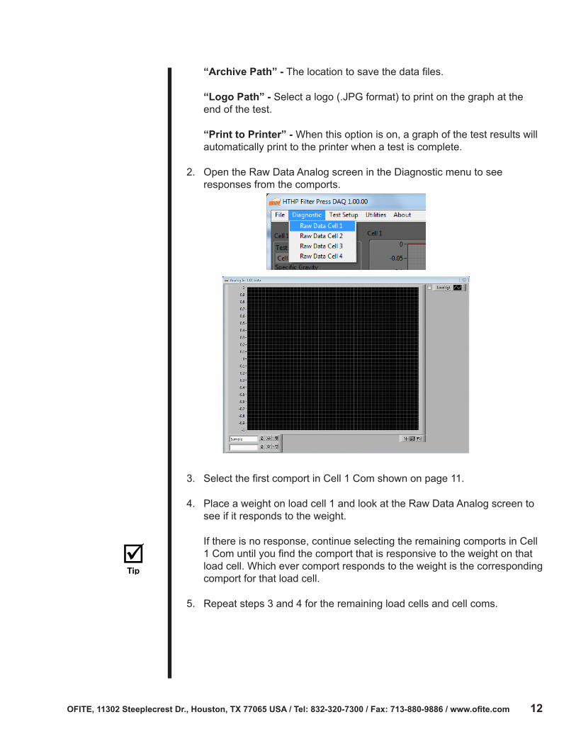
2. Open the Raw Data Analog screen in the Diagnostic menu to see responses from the comports.
3. Select the first comport in Cell 1 Com shown on page 11.
4. Place a weight on load cell 1 and look at the Raw Data Analog screen to see if it responds to the weight.
If there is no response, continue selecting the remaining comports in Cell 1 Com until you find the comport that is responsive to the weight on that load cell. Which ever comport responds to the weight is the corresponding comport for that load cell.
5. Repeat steps 3 and 4 for the remaining load cells and cell coms.

OFITE, 11302 Steeplecrest Dr., Houston, TX 77065 USA / Tel: 832-320-7300 / Fax: 713-880-9886 / www.ofite.com 13
Click the “Start Test” button to open the Load Sample Info dialog box. You can also navigate to this box: Test Setup→Select a cell.
Enter a test name and a specific gravity (1.00 g/cm2). The Specific Gravity displayed is corresponding to the Filtrate Volume for that load sample in the main screen. Click OK.
To view archived tests, open the Open Data Archives file in the File menu options.

OFITE, 11302 Steeplecrest Dr., Houston, TX 77065 USA / Tel: 832-320-7300 / Fax: 713-880-9886 / www.ofite.com 14
Calibrate each load cell (one at a time) prior to testing. This is to be done once each communication port has been confirmed.
1. Navigate to the calibration window – Utilities→Select a Cell Number to calibrate.
2. Place a desired amount of weights onto a load cell.
3. Enter the value of the weight in the 1st set weight (g) field and press the green arrow to display the Raw value.
4. Add desired weight to the load cell.
5. Enter the value of the weight in the 2nd set weight (g) field and press the green arrow to display the Raw value.
6. Add desired weight to the load cell.
7. Enter the value of the weight in the 3rd set weight (g) field and press the green arrow to display the Raw value.
8. Press the “Store Cal” button to save the calibrations and exit.
9. Repeat steps 2 – 8 for the remaining three load cells.
Load Cell Option
Calibration

OFITE, 11302 Steeplecrest Dr., Houston, TX 77065 USA / Tel: 832-320-7300 / Fax: 713-880-9886 / www.ofite.com 15
Appendix Driver Install
A driver is software that a device (the HTHP Filter Press) uses to work with a computer. Every HTHP Filter Press requires a driver to work with your PC before the software can be operated.
1. Insert the software/driver CD to the computer and select the file labeled: CDM20828.exe
2. A prompt will open, asking if you want to run this file. Press Enter or click “Run”.
3. The FTDI CDM Driver will open to allow you to extract the driver and launch the installer. Click “Extract”.
4. A welcome window will open. Click “Next”.

OFITE, 11302 Steeplecrest Dr., Houston, TX 77065 USA / Tel: 832-320-7300 / Fax: 713-880-9886 / www.ofite.com 16
5. Accept the licence agreement and click “Next”.
6. Once the driver installation is complete, Click “Finish”.
7. Plug he USB portion of the USB/RS232 cable (#130-76-19) to the computer.
The computer will continue installing the software. Wait for it to finish installing.
8. Once the installation is complete, navigate to the Device Manager: Click the Start Menu. Open the “Control Panel”. Click the “Hardware and Sound” link. Click on the Device Manager link in the “Devices and Printers” options.

OFITE, 11302 Steeplecrest Dr., Houston, TX 77065 USA / Tel: 832-320-7300 / Fax: 713-880-9886 / www.ofite.com 17
9. Confirm which communication port (COM Port) the USB Serial Port is located in. The window below is indicating that this sample port was connected to “COM3” which can be a different COM# depending on the computer and the port it was connected to. This is the COM Port that the driver has been assigned to.
10. Open the Options screen in the software. Choose the COM port listed in Device Manager.

OFITE, 11302 Steeplecrest Dr., Houston, TX 77065 USA / Tel: 832-320-7300 / Fax: 713-880-9886 / www.ofite.com 18
Warranty and Return Policy
Warranty:OFI Testing Equipment, Inc. (OFITE) warrants that the products shall be free from liens and defects in title, and shall conform in all respects to the terms of the sales order and the specifications applicable to the products. All products shall be furnished subject to OFITE’s standard manufacturing variations and practices. Unless the warranty period is otherwise extended in writing, the following warranty shall apply: if, at any time prior to twelve (12) months from the date of invoice, the products, or any part thereof, do not conform to these warranties or to the specifications applicable thereto, and OFITE is so notified in writing upon discovery, OFITE shall promptly repair or replace the defective products. Notwithstanding the foregoing, OFITE’s warranty obligations shall not extend to any use by the buyer of the products in conditions more severe than OFITE’s recommendations, nor to any defects which were visually observable by the buyer but which are not promptly brought to OFITE’s attention.
In the event that the buyer has purchased installation and commissioning services on applicable products, the above warranty shall extend for an additional period of twelve (12) months from the date of the original warranty expiration for such products.
In the event that OFITE is requested to provide customized research and development for the buyer, OFITE shall use its best efforts but makes no guarantees to the buyer that any products will be provided.
OFITE makes no other warranties or guarantees to the buyer, either express or implied, and the warranties provided in this clause shall be exclusive of any other warranties including ANY IMPLIED OR STATUTORY WARRANTIES OF FITNESS FOR PURPOSE, MERCHANTABILITY, AND OTHER STATUTORY REMEDIES WHICH ARE WAIVED.
This limited warranty does not cover any losses or damages that occur as a result of:
• Improper installation or maintenance of the products
• Misuse
• Neglect
• Adjustment by non-authorized sources
• Improper environment
• Excessive or inadequate heating or air conditioning or electrical power failures, surges, or other irregularities
• Equipment, products, or material not manufactured by OFITE
• Firmware or hardware that have been modified or altered by a third party
• Consumable parts (bearings, accessories, etc.)
Returns and Repairs:Items being returned must be carefully packaged to prevent damage in shipment and insured against possible damage or loss. OFITE will not be responsible for equipment damaged due to insufficient packaging.
Any non-defective items returned to OFITE within ninety (90) days of invoice are subject to a 15% restocking fee. Items returned must be received by OFITE in original condition for it to be accepted. Reagents and special order items will not be accepted for return or refund.
OFITE employs experienced personnel to service and repair equipment manufactured by us, as well as other companies. To help expedite the repair process, please include a repair form with all equipment sent to OFITE for repair. Be sure to include your name, company name, phone number, email address, detailed description of work to be done, purchase order number, and a shipping address for returning the equipment. All repairs performed as “repair as needed” are subject to the ninety (90) day limited warranty. All “Certified Repairs” are subject to the twelve (12) month limited warranty.
Returns and potential warranty repairs require a Return Material Authorization (RMA) number. An RMA form is available from your sales or service representative.
Please ship all equipment (with the RMA number for returns or warranty repairs) to the following address:
OFI Testing Equipment, Inc. Attn: Repair Department 11302 Steeplecrest Dr. Houston, TX 77065 USA
OFITE also offers competitive service contracts for repairing and/or maintaining your lab equipment, including equipment from other manufacturers. For more information about our technical support and repair services, please contact [email protected].