4 - bracing strut systems - issue 3 tech file - mgf.ltd.uk · bracing strut systems ... prior to...
TRANSCRIPT

01942 402 [email protected]
MGF 200 Series Strut 4.1
MGF 300 Series Strut 4.2
MGF 400 Series Strut 4.3
MGF 600 Series Strut 4.4
MGF 1000 Series Strut 4.5
BRACING STRUT SYSTEMSSECTION 4

MGF Bracing Strut System at the Chiltern Project for CJ O’Shea in London
MG
F 20
0 SE
RIE
S ST
RU
TM
GF
TEC
HN
ICAL
FIL
E
4.1.1Issue 3
4 1 1
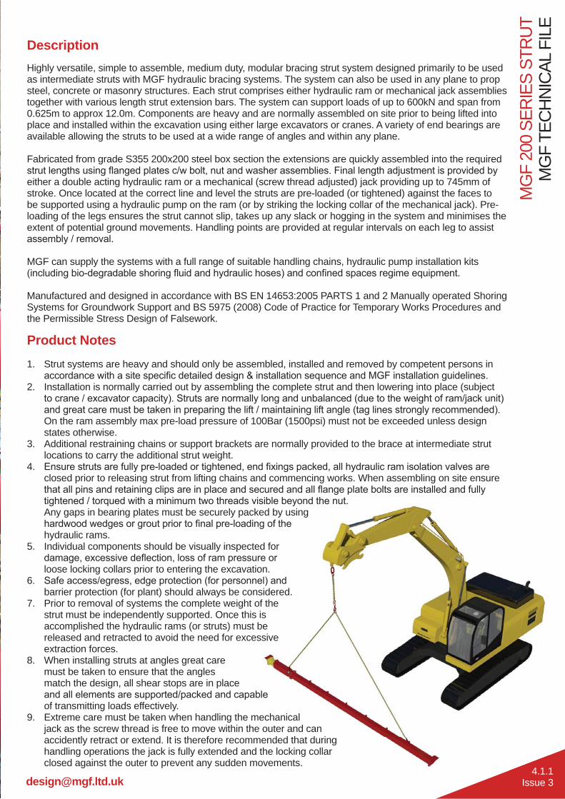
DescriptionHighly versatile, simple to assemble, medium duty, modular bracing strut system designed primarily to be used as intermediate struts with MGF hydraulic bracing systems. The system can also be used in any plane to prop steel, concrete or masonry structures. Each strut comprises either hydraulic ram or mechanical jack assemblies together with various length strut extension bars. The system can support loads of up to 600kN and span from 0.625m to approx 12.0m. Components are heavy and are normally assembled on site prior to being lifted into place and installed within the excavation using either large excavators or cranes. A variety of end bearings are available allowing the struts to be used at a wide range of angles and within any plane.
Fabricated from grade S355 200x200 steel box section the extensions are quickly assembled into the required
either a double acting hydraulic ram or a mechanical (screw thread adjusted) jack providing up to 745mm of stroke. Once located at the correct line and level the struts are pre-loaded (or tightened) against the faces to be supported using a hydraulic pump on the ram (or by striking the locking collar of the mechanical jack). Pre-loading of the legs ensures the strut cannot slip, takes up any slack or hogging in the system and minimises the extent of potential ground movements. Handling points are provided at regular intervals on each leg to assist
MGF can supply the systems with a full range of suitable handling chains, hydraulic pump installation kits
Manufactured and designed in accordance with BS EN 14653:2005 PARTS 1 and 2 Manually operated Shoring Systems for Groundwork Support and BS 5975 (2008) Code of Practice for Temporary Works Procedures and the Permissible Stress Design of Falsework.
Product Notes1. Strut systems are heavy and should only be assembled, installed and removed by competent persons in
2. Installation is normally carried out by assembling the complete strut and then lowering into place (subject
On the ram assembly max pre-load pressure of 100Bar (1500psi) must not be exceeded unless design states otherwise.
3. Additional restraining chains or support brackets are normally provided to the brace at intermediate strut locations to carry the additional strut weight.
4. closed prior to releasing strut from lifting chains and commencing works. When assembling on site ensure
Any gaps in bearing plates must be securely packed by using
hydraulic rams.5. Individual components should be visually inspected for
loose locking collars prior to entering the excavation.6.
barrier protection (for plant) should always be considered.7. Prior to removal of systems the complete weight of the
strut must be independently supported. Once this is accomplished the hydraulic rams (or struts) must be released and retracted to avoid the need for excessive extraction forces.
8. When installing struts at angles great care must be taken to ensure that the angles match the design, all shear stops are in place
of transmitting loads effectively.9. Extreme care must be taken when handling the mechanical
jack as the screw thread is free to move within the outer and can accidently retract or extend. It is therefore recommended that during handling operations the jack is fully extended and the locking collar closed against the outer to prevent any sudden movements.
Tel. 01942 402 704
MG
F TE
CH
NIC
AL F
ILE
MG
F 20
0 SE
RIE
S ST
RU
T
4.1.2Issue 3
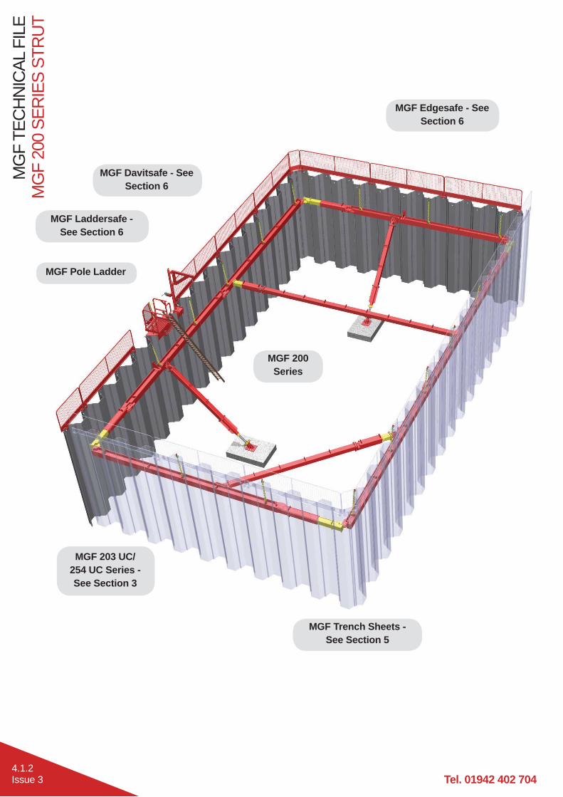
MGF Pole Ladder
MGF Davitsafe - See Section 6
MGF 203 UC/ 254 UC Series - See Section 3
MGF Laddersafe - See Section 6
MGF Edgesafe - See Section 6
MGF Trench Sheets - See Section 5
MGF 200 Series

MG
F 20
0 SE
RIE
S ST
RU
TM
GF
TEC
HN
ICAL
FIL
E
4.1.3Issue 3
Handling PointWLL = 7.0t
Strut assemblies are lifted and handled by attaching MGF lifting
points as shown.
Strut Flange Connection Detail200 Series Struts and Extensions
(300x300x20mm) using 8 No. grade
(recommended min. torque 300Nm).
Top Swivel Bearing Detail The swivel is secured to the UC section by bolting RSA sections to the swivel base plate using 12
and washers.
Base Swivel Bearing Detail The swivel can be secured
bolts.
Vertical Shear Restraint Detail The vertical restraint detail should be used whenever there is a raking prop. It can either be welded to the pan of
sheets or bolted to a concrete wall using anchors.

Tel. 01942 402 704
MG
F TE
CH
NIC
AL F
ILE
MG
F 20
0 SE
RIE
S ST
RU
T
4.1.4Issue 3
Cleat End Bearing Detail The end cleat is bolted to the strut or extension using 4 No. grade 8.8 M20 countersunk bolts
UC section. When using this end detail MGF recommend that restraining chains are used to lash the waler and strut together at each end to prevent
the strut being dislodged if struck accidently.
Knee Brace End Bearing Detail
The swivel is secured to the UC section by bolting RSA sections to the swivel base plate using 12 No.
washers.

MG
F 20
0 SE
RIE
S ST
RU
TM
GF
TEC
HN
ICAL
FIL
E
4.1.5Issue 3
540kN Mechanical Strut
Axial load only
Axial + 10kN accidental load
600kN Hydraulic Strut
Axial load only
Axial + 10kN accidental load
Safe Working Load for MGF 200 Series (kN)
250kN Hydraulic Strut
Axial + 10kN accidental load

Tel. 01942 402 704
MG
F TE
CH
NIC
AL F
ILE
MG
F 20
0 SE
RIE
S ST
RU
T
4.1.6Issue 3
Product Description Product ID
Face to Face Dimension (mm) Weight (kg)Min. Max.
250kN Hydraulic Strut 9.400 625 925 105540kN Mechanical Strut 9.015 1085 1830 147600kN Hydraulic Strut 9.016 1150 1750 375
Product Description Product ID Weight (kg)200 Series 0.25m Extension 9.206 40200 Series 0.5m Extension 9.205 52200 Series 1.0m Extension 9.210 76200 Series 1.5m Extension 9.215 101200 Series 2.0m Extension 9.220 124200 Series 3.0m Extension 9.230 173200 Series 4.0m Extension 9.240 223200 Series 5.0m Extension 9.250 268200 Series 6.0m Extension 9.260 316
540kN mechanical strut assembly comprises inner screw threaded sections and outer sleeved steel sections combined with a threaded collar to provide up to 745mm of leg adjustment.
250kN and 600kN hydraulic strut assemblies comprise of inner and outer sleeved steel box sections housing a double acting (DA) hydraulic ram to provide up to 600mm of leg adjustment.
200 Series extension bars range in length from 0.25m to 6.0m and are connected to each other via 8 No. grade 8.8 M20 bolts

MG
F 20
0 SE
RIE
S ST
RU
TM
GF
TEC
HN
ICAL
FIL
E
4.1.7Issue 3
Extension Bar200x200x8 SHS
Material Grade S355Unit Mass 47.7kg/mAxial SWL 600kN
Moment SWL 100kNmJoint Moment SWL 100kNm
Hydraulic Ram Inner Section Outer Section200x200x12.5 SHS
(+ 4 No. 90x10mm thk. stiffening plates)
250x250x12.5 SHS
Material Grade S355 S355Unit Mass 95.8kg/m 91.9kg/mAxial SWL 600kN 600kN
Moment SWL 100kNm 100kNm
Mechanical Jack Inner Section Outer Section
100x12.5 thk. CHS 120x120x8 SHS
Material Grade ST52 S355Screw Thread Detail
Unit Mass 27.0kg/m 50.8kg/mAxial SWL 540kN 540kN
Moment SWL 22kNm 100kNm

Tel. 01942 402 704
MG
F TE
CH
NIC
AL F
ILE
MG
F 20
0 SE
RIE
S ST
RU
T
4.1.8Issue 3
Hydraulic Ram Inner Section Outer Section140x140x8 SHS 160x160x8 SHS
Material Grade S355 S355Unit Mass 32.6kg/m 37.6kg/mAxial SWL 250kN 250kN
Moment SWL 50kNm 65kNm
MGF’s new 250kN Hydraulic Strut has been designed for use with 203 UC Series and 254 UC Series Brace as well as MGF’s new 152 UC Waler. It is suitable for narrow trenches and is compatible with 200 Series extensions and adaptors.
When used with the 152 UC Waler the 250kN hydraulic struts must be clamped in position. The 250kN strut can also be used as Endsafe when used in the outermost position.
When used with 203 UC or 254 UC Series Brace the 250kN hydraulic strut can either bear directly onto the UC using end cleats or clamping plates (4.1.11) as above, or connect
using these Strut Adaptors the 200 Series can also be used as an End Protection Strut.

MG
F 20
0 SE
RIE
S ST
RU
TM
GF
TEC
HN
ICAL
FIL
E
4.1.9Issue 3
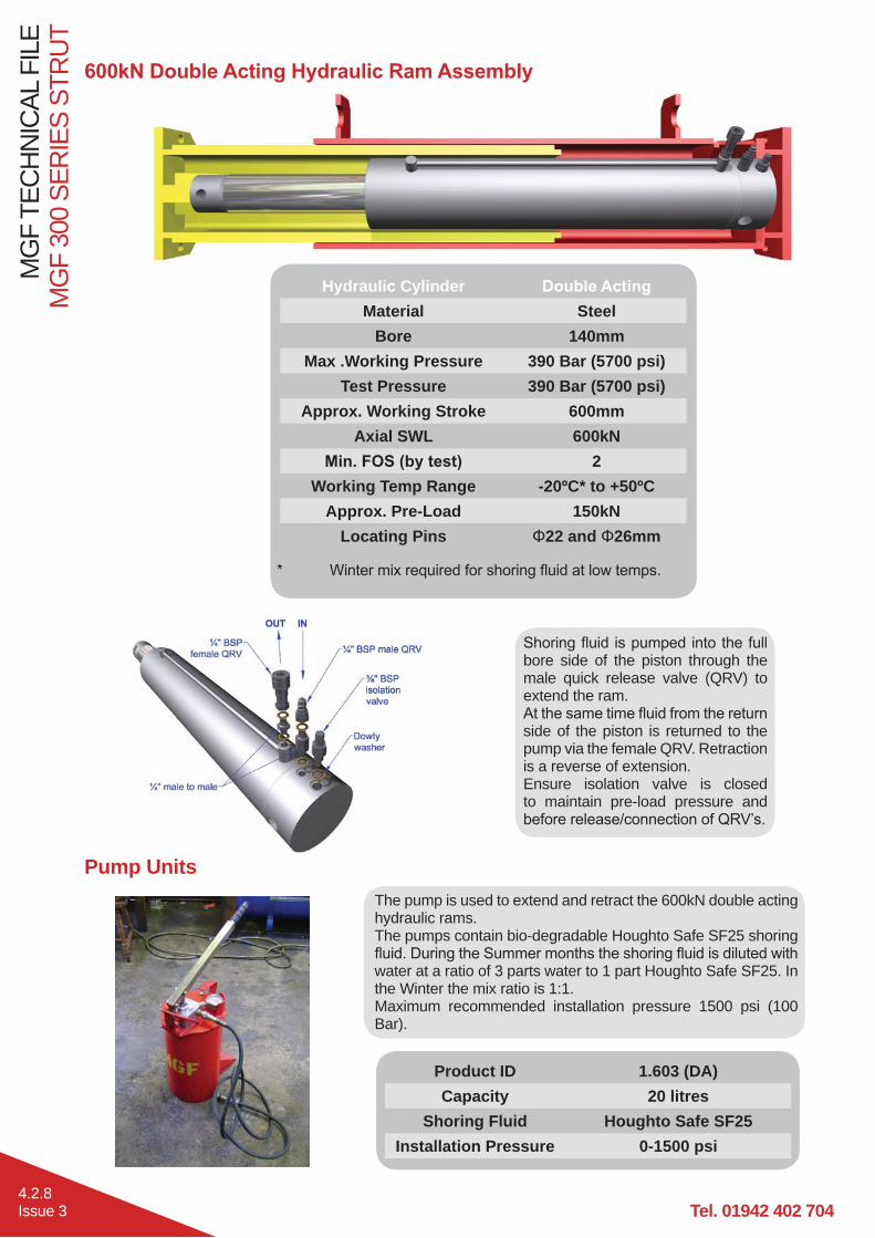
Pump Units
Product ID 1.603 (DA)Capacity 20 litres
Shoring Fluid Houghto Safe SF25Installation Pressure 0-1500 psi
The pump is used to extend and retract the 250kN and 600kN double acting hydraulic rams. The pumps contain bio-degradable Houghto Safe SF25 shoring
water at a ratio of 3 parts water to 1 part Houghto Safe SF25. In the Winter the mix ratio is 1:1.Maximum recommended installation pressure 1500 psi (100 Bar).
bore side of the piston through the male quick release valve (QRV) to extend the ram.
return side of the piston is returned to the pump via the female QRV. Retraction is a reverse of extension.Ensure isolation valve is closed to maintain pre-load pressure
QRV’s.
Hydraulic CylinderMaterial Steel Steel
Bore 85mm 140mmMax .Working Pressure 440 Bar (6400 psi) 390 Bar (5700 psi)
Test Pressure 440 Bar (6400 psi) 390 Bar (5700 psi)Approx. Working Stroke 300mm 600mm
Axial SWL 250kN 600kN2 2
Working Temp Range -20ºC* to +50ºC -20ºC* to +50ºCApprox. Pre-Load 65kN 150kN
Locating Pins 22 22 and 26mm

Tel. 01942 402 704
MG
F TE
CH
NIC
AL F
ILE
MG
F 20
0 SE
RIE
S ST
RU
T
4.1.10Issue 3
200 Series Swivel Type A Type BProduct ID 9.301 9.209 & 9.2095
Weight 75kg 32kgRaking Prop Operating
Range 22°- 40° 65°- 90°
Knee Brace/Cross Strut Operating Range 22°- 65° 65°- 90°
Axial SWL 600kN 600kNSwivel Base Plate 385 x 420 x 30mm thk. (S355) 300 x 300 x 20mm thk. (S275)
Base Plate Hole Details 20 No. 22 holes 8 No. 22 holesPin Detail 62 (080M40/EN8) 50 (708M40/EN19A)
‘Type A’ swivels can be connected directly to concrete structures or the
‘Type B’ swivels can be connected to both the 203 UC and 254 UC Brace Systems by using the 200 Series Clamping Plate as detailed on page 4.1.11.

MG
F 20
0 SE
RIE
S ST
RU
TM
GF
TEC
HN
ICAL
FIL
E
4.1.11Issue 3
200 Series Ancillaries
200 Series End Seating Plate
200 Series Clamping Plate
200/300 Series Vertical Restraint
Product ID 9.314Weight 45kgMaterial
Bolting Details
4 No. grade 8.8 M20
and 8 No. grade 8.8
and washersBearing SWL 600kN
Product ID 9.313Weight 25kgMaterial
Weld Details weld Shear SWL 600kN
Product ID 9.300Weight 15kgMaterial
Bolting Details
4 No. grade 8.8 M20 countersunk
washersBearing SWL 600kN
200 Series 152 UC Waler Clamp
Product ID 9.317Weight 3kgMaterial S275
Bolting Details
2 No. grade 8.8 M20 countersunk
washers
When connecting 200 Series to 152 UC, 2 No. of the above clamps should be attached to each end of the strut.
Tel. 01942 402 704
MG
F TE
CH
NIC
AL F
ILE
MG
F 20
0 SE
RIE
S ST
RU
T
4.1.12Issue 3
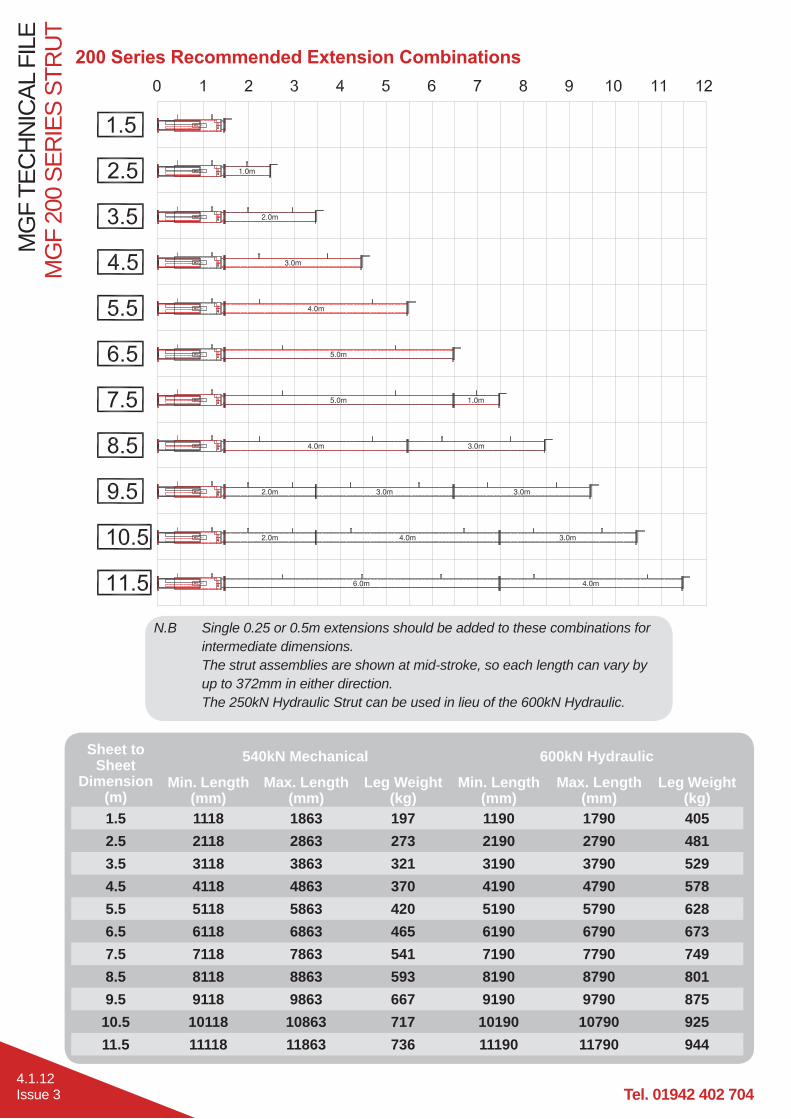
Sheet to Sheet
Dimension (m)
540kN Mechanical 600kN Hydraulic
Min. Length (mm)
Max. Length (mm)
Leg Weight (kg)
Min. Length (mm)
Max. Length (mm)
Leg Weight (kg)
1.5 1118 1863 197 1190 1790 4052.5 2118 2863 273 2190 2790 4813.5 3118 3863 321 3190 3790 5294.5 4118 4863 370 4190 4790 5785.5 5118 5863 420 5190 5790 6286.5 6118 6863 465 6190 6790 6737.5 7118 7863 541 7190 7790 7498.5 8118 8863 593 8190 8790 8019.5 9118 9863 667 9190 9790 875
10.5 10118 10863 717 10190 10790 92511.5 11118 11863 736 11190 11790 944
N.B Single 0.25 or 0.5m extensions should be added to these combinations for intermediate dimensions. The strut assemblies are shown at mid-stroke, so each length can vary by up to 372mm in either direction. The 250kN Hydraulic Strut can be used in lieu of the 600kN Hydraulic.

MG
F 20
0 SE
RIE
S ST
RU
TM
GF
TEC
HN
ICAL
FIL
E
4.1.13Issue 3
Typical Raking Prop Application
Typical bearing detail on RC capping beam.
Typical bearing detail on concrete thrust
block.

MGF 200 Series Struts

MG
F 30
0 SE
RIE
S ST
RU
TM
GF
TEC
HN
ICAL
FIL
E
4.2.1Issue 3
DescriptionHighly versatile, simple to assemble, medium duty, modular bracing strut system designed primarily to be used as intermediate struts with MGF hydraulic bracing systems. The system can also be used in any plane to prop steel, concrete or masonry structures. Each strut comprises either hydraulic ram or mechanical jack assemblies together with various length strut extension bars. The system can support loads of up to 600kN and span from 1.1m to approx 18.0m and can incorporate a central cruciform bar offering intermediate vertical support to perpendicular struts. Components are heavy and are normally assembled on site prior to being lifted into place and installed within the excavation using either large excavators or cranes. A variety of end bearings are available allowing the struts to be used at a wide range of angles and within any plane.
Fabricated from grade S355 300x300 steel box section the extensions are quickly assembled into the required
either a double acting hydraulic ram or a mechanical (screw thread adjusted) jack providing up to 745mm of stroke. Once located at the correct line and level the struts are pre-loaded (or tightened) against the faces to be supported using a hydraulic pump on the ram (or by striking the locking collar of the mechanical jack). Pre-loading of the legs ensures the strut cannot slip, takes up any slack or hogging in the system and minimises the extent of potential ground movements. Handling points are provided at regular intervals on each leg to assist
MGF can supply the systems with a full range of suitable handling chains, hydraulic pump installation kits
Manufactured and designed in accordance with BS EN 14653:2005 PARTS 1 and 2 Manually operated Shoring Systems for Groundwork Support and BS 5975 (2008) Code of Practice for Temporary Works Procedures and the Permissible Stress Design of Falsework.
Product Notes1. Strut systems are heavy and should only be assembled, installed and removed by competent persons in
2. Installation is normally carried out by assembling the complete strut and then lowering into place (subject
On the ram assembly max pre-load pressure of 100Bar (1500psi) must not be exceeded unless design states otherwise.
3. Additional restraining chains or support brackets are normally provided to the brace at intermediate strut locations to carry the additional strut weight.
4. closed prior to releasing strut from lifting chains and commencing works. When assembling on site ensure
Any gaps in bearing plates must be securely packed by using hardwood
5. Individual components should be visually inspected for damage,
to entering the excavation.6.
barrier protection (for plant) should always be considered.7. Prior to removal of systems the complete weight of the
strut must be independently supported. Once this is accomplished the hydraulic rams (or struts) must be released and retracted to avoid the need for excessive extraction forces.
8. When installing struts at angles great care must be taken to ensure that the angles match the design, all shear stops
capable of transmitting loads effectively.9. Extreme care must be taken when handling the mechanical
jack as the screw thread is free to move within the outer and can accidently retract or extend. It is therefore recommended that during handling operations the jack is fully extended and the locking collar closed against the outer to prevent any sudden movements.

Tel. 01942 402 704
MG
F TE
CH
NIC
AL F
ILE
MG
F 30
0 SE
RIE
S ST
RU
T
4.2.2Issue 3
MGF Pole Ladder
MGF Davitsafe - See Section 6
MGF 203UC/ 254 UC Series - See Section 3
MGF Laddersafe - See Section 6
MGF Edgesafe - See Section 6
MGF Trench Sheets - See Section 5
MGF 300 Series
Cruciform strut option
using 254 UC 200/300 Series Strut Adaptors Note: 300 Series Cruciforms should
greater than 12.0m

MG
F 30
0 SE
RIE
S ST
RU
TM
GF
TEC
HN
ICAL
FIL
E
4.2.3Issue 3
Handling PointWLL = 7.0t
Strut assemblies are lifted and handled by attaching MGF lifting
points as shown.
Top Swivel Bearing Detail The swivel is secured to the UC section by bolting RSA sections to the swivel base plate using 12
and washers.
Base Swivel Bearing Detail The swivel can be secured
bolts.
Vertical Shear Restraint Detail The vertical restraint detail should be used whenever there is a raking prop. It can either be welded to the pan of
sheets or bolted to a concrete wall using anchors.
Strut Flange Connection Detail300 Series Strut assemblies and swivel plates are connected to 300 Series Extensions using a transition plate (400x400x20mm), 8 No. grade 8.8 M20
(recommended min. torque 300Nm).

Tel. 01942 402 704
MG
F TE
CH
NIC
AL F
ILE
MG
F 30
0 SE
RIE
S ST
RU
T
4.2.4Issue 3
Cleat End Bearing Detail The end cleat is bolted to the strut or extension
washers. The cleat then sits on the UC section. When using this end detail MGF recommend that restraining chains are used to lash the waler and
strut together at each end to prevent the strut being dislodged if struck accidently.
Knee Brace End Bearing Detail
The swivel is secured to the UC section by bolting RSA sections to the swivel base plate using 12 No.
washers.

MG
F 30
0 SE
RIE
S ST
RU
TM
GF
TEC
HN
ICAL
FIL
E
4.2.5Issue 3
540kN Mechanical Strut
Axial load only
Axial + 10kN accidental load
600kN Hydraulic Strut
Axial + 10kN accidental load
Safe Working Load for MGF 300 Series (kN)
300
350
400
450
500
550
600
650
1 2 3 4 5 6 7 8 9 10 11 12 13 14 15
Max
imum
SW
L (k
N)
Strut Span (m)

Tel. 01942 402 704
MG
F TE
CH
NIC
AL F
ILE
MG
F 30
0 SE
RIE
S ST
RU
T
4.2.6Issue 3
Product Description Product ID
Face to Face Dimension (mm) Weight (kg)Min. Max.
540kN Mechanical Strut 9.015 1085 1830 147kg600kN Hydraulic Strut 9.016 1150 1750 375kg
Product Description Product ID Weight (kg)300 Series 0.5m Extension 9.000 107300 Series 1.0m Extension 9.001 163300 Series 2.0m Extension 9.002 280300 Series 3.0m Extension 9.003 388300 Series 5.0m Extension 9.005 610
540kN mechanical strut assembly
comprises inner screw threaded sections and
outer sleeved steel sections combined
with a threaded collar to provide up
to 745mm of leg adjustment.
600kN hydraulic strut assembly comprises
inner and outer sleeved steel box sections
housing a double acting (DA) hydraulic ram to
provide up to 600mm of leg adjustment.
300 Series extension bars range in length
from 0.5m to 5.0m and are connected to each other via 8 No. grade
and washers.

MG
F 30
0 SE
RIE
S ST
RU
TM
GF
TEC
HN
ICAL
FIL
E
4.2.7Issue 3
Extension Bar300x300x12.5 SHS
Material Grade S355Unit Mass 112.0kg/mAxial SWL 600kN
Moment SWL 308kNmJoint Moment SWL 100kNm
Hydraulic Ram Inner Section Outer Section200x200x12.5 SHS
(+ 4 No. 90x10mm thk. stiffening plates)
250x250x12.5 SHS
Material Grade S355 S355Unit Mass 95.8kg/m 91.9kg/mAxial SWL 600kN 600kN
Moment SWL 100kNm 100kNm
Mechanical Jack Inner Section Outer Section
100x12.5 thk. CHS 120x120x8 SHS
Material Grade ST52 S355Screw Thread Detail
Unit Mass 27.0kg/m 50.8kg/mAxial SWL 540kN 540kN
Moment SWL 22kNm 100kNm
Tel. 01942 402 704
MG
F TE
CH
NIC
AL F
ILE
MG
F 30
0 SE
RIE
S ST
RU
T
4.2.8Issue 3
Pump Units
Hydraulic CylinderMaterial Steel
Bore 140mmMax .Working Pressure 390 Bar (5700 psi)
Test Pressure 390 Bar (5700 psi)Approx. Working Stroke 600mm
Axial SWL 600kN2
Working Temp Range -20ºC* to +50ºCApprox. Pre-Load 150kN
Locating Pins 22 and 26mm
Product ID 1.603 (DA)Capacity 20 litres
Shoring Fluid Houghto Safe SF25Installation Pressure 0-1500 psi
The pump is used to extend and retract the 600kN double acting hydraulic rams. The pumps contain bio-degradable Houghto Safe SF25 shoring
water at a ratio of 3 parts water to 1 part Houghto Safe SF25. In the Winter the mix ratio is 1:1.Maximum recommended installation pressure 1500 psi (100 Bar).
bore side of the piston through the male quick release valve (QRV) to extend the ram.
side of the piston is returned to the pump via the female QRV. Retraction is a reverse of extension.Ensure isolation valve is closed to maintain pre-load pressure and

MG
F 30
0 SE
RIE
S ST
RU
TM
GF
TEC
HN
ICAL
FIL
E
4.2.9Issue 3
200 Series Swivel Type A Type BProduct ID 9.301 9.209 & 9.2095
Weight 75kg 32kgRaking Prop Operating
Range 22°- 40° 0°- 28°
Knee Brace/Cross Strut Operating Range 22°- 65° 65°- 90°
Axial SWL 600kN 600kNSwivel Base Plate 385 x 420 x 30mm thk. (S355) 300 x 300 x 20mm thk. (S275)
Base Plate Hole Details 20 No. 22 holes 8 No. 22 holesPin Detail 62 (080M40/EN8) 50 (708M40/EN19A)
Systems by bolting on the associated clamp assemblies.
‘Type B’ swivels can be connected to both the 203 UC and 254 UC Brace Systems by using the 200 Series Clamping Plate as detailed on page 4.2.10.

Tel. 01942 402 704
MG
F TE
CH
NIC
AL F
ILE
MG
F 30
0 SE
RIE
S ST
RU
T
4.2.10Issue 3
300 Series Ancillaries
200/300 Series End Seating Plate
200 Series Clamping Plate
200/300 Series Vertical Restraint
Product ID 9.314Weight 45kgMaterial
Bolting Details
4 No. grade 8.8 M20
and 8 No. grade 8.8
and washersBearing SWL 600kN
Product ID 9.313Weight 25kgMaterial
Weld Details weld Shear SWL 600kN
Product ID 9.3005Weight 27kgMaterial
Bolting Details
4 No. grade 8.8 M20
washers
Bearing SWL 600kN
300 Series Cruciform
Product ID 9.315Weight 140kgMaterial
Bolting Details c/w nuts and washersStrut Adaptor SWL 600kN
Axial SWL 600kNMoment SWL 308kNm

MG
F 30
0 SE
RIE
S ST
RU
TM
GF
TEC
HN
ICAL
FIL
E
4.2.11Issue 3
Sheet to Sheet
Dimension (m)
540kN Mechanical 600kN Hydraulic
Min. Length (mm)
Max. Length (mm)
Leg Weight (kg)
Min. Length (mm)
Max. Length (mm)
Leg Weight (kg)
6.5 6138 6883 852 6210 6810 10277.5 7138 7883 1015 7210 7810 11908.5 8138 8883 1132 8210 8810 13079.5 9138 9883 1240 9210 9810 1415
10.5 10138 10883 1412 10210 10810 158711.5 11138 11883 1520 11210 11810 169512.5 12138 12883 1625 12210 12810 180013.5 13138 13883 1742 13210 13810 191714.5 14138 14883 1850 14210 14810 202515.5 15138 15883 2022 15210 15810 219716.5 16138 16883 2072 16210 16810 224717.5 17138 17883 2235 17210 17810 2410
N.B Single 0.5m extensions should be added to these combinations for intermediate dimensions. The strut assemblies are shown at mid-stroke, so each length can vary by up to 372mm in either direction.
Tel. 01942 402 704
MG
F TE
CH
NIC
AL F
ILE
MG
F 30
0 SE
RIE
S ST
RU
T
4.2.12Issue 3
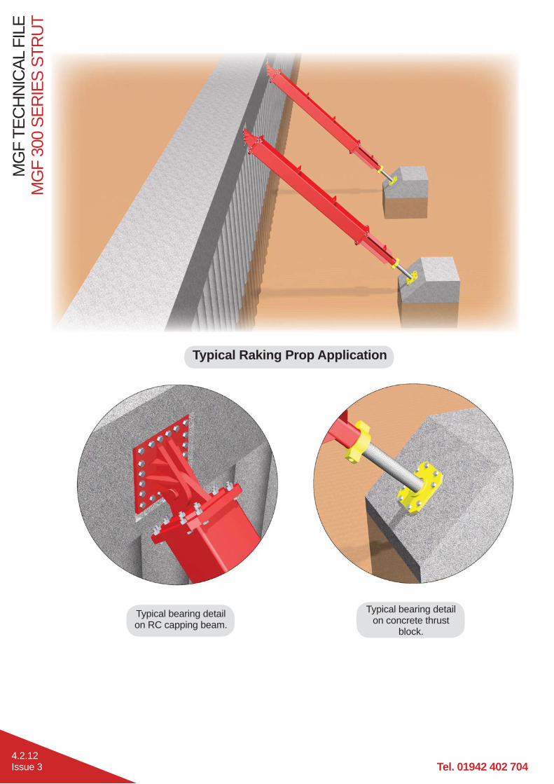
Typical Raking Prop Application
Typical bearing detail on RC capping beam.
Typical bearing detail on concrete thrust
block.

MG
F 40
0 SE
RIE
S ST
RU
TM
GF
TEC
HN
ICAL
FIL
E
4.3.1Issue 3
DescriptionHighly versatile, simple to assemble, heavy duty, modular bracing strut system designed primarily to be used as intermediate struts with MGF hydraulic bracing systems. The system can also be used in any plane to prop steel, concrete or masonry structures. Each strut comprises either hydraulic ram or mechanical jack assemblies together with various length strut extension bars. The system can support loads of up to 2500kN and span from 1.6m to approx 24.0m and can incorporate a central cruciform bar offering intermediate vertical support to perpendicular struts. Components are heavy and are normally assembled on site prior to being lifted into place and installed within the excavation using either large excavators or cranes. A variety of end bearings are available allowing the struts to be used at a wide range of angles and within any plane.
Fabricated from grade S355 400x400 steel box section the extensions are quickly assembled into the required
either a double acting hydraulic ram or a mechanical (screw thread adjusted) jack providing up to 800mm of stroke. Once located at the correct line and level the struts are pre-loaded (or tightened) against the faces to be supported using a hydraulic pump on the ram (or by striking the locking collar of the mechanical jack). Pre-loading of the legs ensures the strut cannot slip, takes up any slack or hogging in the system and minimises the extent of potential ground movements. Handling points are provided at regular intervals on each leg to assist
MGF can supply the systems with a full range of suitable handling chains, hydraulic pump installation kits
Manufactured and designed in accordance with BS EN 14653:2005 PARTS 1 and 2 Manually operated Shoring Systems for Groundwork Support and BS 5975 (2008) Code of Practice for Temporary Works Procedures and the Permissible Stress Design of Falsework.
Product Notes1. Strut systems are very heavy and should only be assembled, installed and removed by competent persons
2. Installation is normally carried out by assembling the complete strut and then lowering into place (subject
On the ram assembly max pre-load pressure of 100Bar (1500psi) must not be exceeded unless design states otherwise.
3. Additional restraining chains or support brackets are normally provided to the brace at intermediate strut locations to carry the additional strut weight.
4. hydraulic ram isolation valves are closed prior to releasing strut from lifting chains and commencing works. When assembling on site ensure that all
threads visible beyond the nut. Any gaps in bearing plates must be securely packed by using hardwood wedges or
5. Individual components should be visually inspected
pressure or loose locking collars prior to entering the excavation.
6. and barrier protection (for plant) should always be considered.
7. Prior to removal of systems the complete weight of the strut must be independently supported. Once this is accomplished the hydraulic rams (or struts) must be released and retracted to avoid the need for excessive extraction forces.
8. When installing struts at angles great care must be taken to ensure that the
packed and capable of transmitting loads effectively.9. Extreme care must be taken when handling the mechanical jack as the screw thread can
detach from the outer if fully wound out.

Tel. 01942 402 704
MG
F TE
CH
NIC
AL F
ILE
MG
F 40
0 SE
RIE
S ST
RU
T
4.3.2Issue 3
MGF Pole Ladder
MGF Davitsafe - See Section 6
MGF 406 UC Series - See Section 3
MGF Laddersafe - See Section 6
MGF Edgesafe - See Section 6
MGF Trench Sheets - See Section 5
MGF 400 Series

MG
F 40
0 SE
RIE
S ST
RU
TM
GF
TEC
HN
ICAL
FIL
E
4.3.3Issue 3
Handling PointWLL = 7.0t
Strut assemblies are lifted and handled by attaching MGF lifting
points as shown.
Strut Flange Connection Detail400 Series Struts and Extensions are connected
washers (recommended min. torque 400Nm).
Top Swivel Bearing Detail The swivel hooks over the
and when the strut is pre-loaded the birds mouth detail bears onto
Base Swivel Bearing Detail The swivel can be secured
bolts.
Vertical Shear Restraint Detail The vertical restraint detail should be used whenever there is a raking prop. It can either be welded to the pan of
sheets or bolted to a concrete wall using anchors.

Tel. 01942 402 704
MG
F TE
CH
NIC
AL F
ILE
MG
F 40
0 SE
RIE
S ST
RU
T
4.3.4Issue 3
Cleat End Bearing Detail The end cleat is bolted to the strut or extension using 9 No. grade 8.8 M24 countersunk bolts
UC section. When using this end detail MGF recommend that restraining chains are used to lash the waler and strut together at each end to prevent
the strut being dislodged if struck accidently.
Knee Brace End Bearing Detail
The swivel is secured to the UC section using 2 No. swivel clamps as detailed on page 4.3.13 using 8 No. grade 8.8 M30

MG
F 40
0 SE
RIE
S ST
RU
TM
GF
TEC
HN
ICAL
FIL
E
4.3.5Issue 3
1250kN Mechanical/Hydraulic Strut
Axial load only2500kN Hydraulic Strut
Axial load only
Axial + 10kN accidental load
Safe Working Load for MGF 400 Series (kN)
1700
1800
1900
2000
2100
2200
2300
2400
2500
2600ax
imum
SW
L (k
N)
1000
1100
1200
1300
1400
1500
1600
1700
1800
1900
2000
2100
2200
2300
2400
2500
2600
10 11 12 13 14 15 16 17 18 19 20 21 22 23 24
Max
imum
SW
L (k
N)
Strut Span (m)

Tel. 01942 402 704
MG
F TE
CH
NIC
AL F
ILE
MG
F 40
0 SE
RIE
S ST
RU
T
4.3.6Issue 3
Product Description Product ID
Face to Face Dimension (mm) Weight (kg)Min. Max.
1250kN Mechanical Strut 9.701 795 1170 3261250kN Hydraulic Strut 8.400 1476 2276 10472500kN Hydraulic Strut 8.500 1685 2485 1716
1250kN and 2500kN hydraulic strut assembly comprises inner and outer sleeved steel box sections housing a double acting (DA) hydraulic ram to provide up to 800mm of leg adjustment.
400 Series extension bars range in length from 0.25m to 10.0m and are connected to each other via 12 No. grade 8.8 M24 bolts
Product Description Product ID Weight (kg)400 Series 0.25m Extension 9.706 165400 Series 0.5m Extension 9.705 214400 Series 1.0m Extension 9.710 310400 Series 2.0m Extension 9.720 505400 Series 3.0m Extension 9.730 697400 Series 4.0m Extension 9.740 889400 Series 5.0m Extension 9.750 1083400 Series 6.0m Extension 9.760 1275400 Series 7.0m Extension 9.770 1465400 Series 8.0m Extension 9.780 1849
400 Series 10.0m Extension 9.799 2048
1250kN mechanical strut assembly comprises inner threaded rod and outer threaded tube providing up to 400mm of leg adjustment.
Handling Point WLL = 8t

MG
F 40
0 SE
RIE
S ST
RU
TM
GF
TEC
HN
ICAL
FIL
E
4.3.7Issue 3
Extension Bar400x400x16 SHS
Material Grade S355Unit Mass 191.0kg/mAxial SWL 2500kN
Moment SWL 703kNmJoint Moment SWL 277kNm
Mechanical Jack Inner Section Outer Section
127x25.4 thk. CHS152.4x19.1 thk. CHS
plates)Material Grade ST52 S355
Screw Thread Detail 5” ACMEUnit Mass 63.6kg/m 105kgAxial SWL 1250kN 1250kN
Moment SWL 60kNm 277kNm

Tel. 01942 402 704
MG
F TE
CH
NIC
AL F
ILE
MG
F 40
0 SE
RIE
S ST
RU
T
4.3.8Issue 3
Hydraulic Ram Inner Section Outer Section350x350x16 SHS
(+ 8 No. 100x6 thk. stiffening plates)
400x400x16 SHS
Material Grade S355 S355Unit Mass 166kg/m 191kg/mAxial SWL 1250kN 1250kN
Moment SWL 277kNm 277kNm
Hydraulic Ram Inner Section Outer Section400x400x16 SHS 450x450x20 SHS
Material Grade S355 S355Unit Mass 191kg/m 275kg/mAxial SWL 2500kN 2500kN
Moment SWL 277kNm 277kNm

MG
F 40
0 SE
RIE
S ST
RU
TM
GF
TEC
HN
ICAL
FIL
E
4.3.9Issue 3
Hydraulic CylinderMaterial Steel Steel
Bore 200mm 250mmMax. Working Pressure 400 Bar (5800 psi) 500 Bar (7250 psi)
Test Pressure 400 Bar (5800 psi) 500 Bar (7250 psi)Approx. Working Stroke 800mm 800mm
Axial SWL 1250kN 2500kN2 2
Working Temp Range -50ºC to +50ºC -50ºC to +50ºCApprox. Pre-Load 300kN 500kN
Locating Pins 30 30
full bore side of the piston through the male quick release valve (QRV) to extend the ram.
the return side of the piston is returned to the pump via the female QRV. Retraction is a reverse of extension.Ensure isolation valve is closed to maintain pre-load pressure
QRV’s.
Motorised Pump Units
Electric Pump Diesel PumpRating 8kW
Product ID 8.4001 / 8.4003 8.4006Capacity 120 / 190 litres 100 litres
Shoring Fluid Houghto Safe SF25 Houghto Safe SF25Installation Pressure 0-1500 psi 0-1500 psi
The motorised pumps are used to extend and retract the 400 Series double acting hydraulic rams. The pumps contain neat bio-degradable Houghto
Maximum recommended installation pressure 1500 psi (100 Bar).MGF supply 2 different types of motorised pump, electric and diesel.

Tel. 01942 402 704
MG
F TE
CH
NIC
AL F
ILE
MG
F 40
0 SE
RIE
S ST
RU
T
4.3.10Issue 3
400 Series Swivel Type A Type BProduct ID 9.704 9.315
Weight 264kg 320kgRaking Prop Operating
Range 22°- 40° 0°- 28°
Knee Brace/Cross Strut Operating Range 22°- 65° 65°- 90°
Axial SWL 2500kN 2500kNSwivel Base Plate 500 x 600 x 30mm thk. (S355) 600 x 600 x 40mm thk. (S355)
Base Plate Hole Details 14 No. 32 holes 16 No. 32 holesPin Detail 90 (817M40/EN24T) 90 (817M40/EN24T)
These swivels can be connected directly to concrete structures or the 406 UC Brace Systems by bolting on the associated clamp assemblies detailed on page 4.3.13.
Type B Swivel base plate also available as 700 x 600 x 40 (product ID 9.310) - this type is not suitable
beams.

MG
F 40
0 SE
RIE
S ST
RU
TM
GF
TEC
HN
ICAL
FIL
E
4.3.11Issue 3
Type A swivels can be connected directly to the 406 UC Brace Systems.
Birdsmouth Type A Type BProduct ID 9.312 9.3125
Weight 309kg 225kgRaking Prop Operating
Range 22°- 40° 22°- 40°
Axial SWL 2500kN 2500kNBearing Plate 20mm thk. (S355) 20mm thk. (S355)
Bearing Plate Hole Details 8 No. 26 holes 2 No. 26 holesPin Detail 90 (817M40/EN24T) 90 (817M40/EN24T)
Type B swivels can bear directly onto the corners of concrete structures such as pile caps or capping beams.

Tel. 01942 402 704
MG
F TE
CH
NIC
AL F
ILE
MG
F 40
0 SE
RIE
S ST
RU
T
4.3.12Issue 3
400 Series Ancillaries
400 Series End Seating Plate
400 Series Vertical Restraint
Product ID 8.4002Weight 35kgMaterial
Weld Details weld Shear SWL 2500kN
Product ID 9.703Weight 102kgMaterial
Bolting Details
9 No. grade 8.8 M24 countersunk
washersBearing SWL 2500kN
400 Series Cruciform
Product ID 9.609Weight 475kgMaterial
Bolting Details c/w nuts and washersStrut Adaptor SWL 1250kN
Axial SWL 1250kNMoment SWL 703kNm
Max. Span 16m

MG
F 40
0 SE
RIE
S ST
RU
TM
GF
TEC
HN
ICAL
FIL
E
4.3.13Issue 3
2500kN Swivel Clamping Plates Type A
Swivel Clamp Type A is to be used on 2500kN Swivel Type A, when used on a knee brace connected to
Swivel Clamp Type B is to be used on 2500kN Swivel Type B, when used as a cross strut connected
Desc. Swivel Clamp Type A Swivel Clamp Type B Modular Swivel Cleat
Product ID 8.303 (305 UC)8.40016 (406 UC)
8.304 (305 UC)8.40017 (406 UC) 9.809
Weight 34kg (305 UC)46kg (406 UC)
45kg (305 UC)54kg (406 UC) 53kg
Material30mm & 25mm thk. (305
UC) or 40mm thk. (406 UC) 30mm & 25mm thk. (305
UC) or 40mm thk. (406 UC)
Bolting Details c/w nuts and washers c/w nuts and washers
5 No. M30 grade 8.8
washersBearing SWL 2500kN 2500kN -Shear SWL - - 700kN
2500kN Swivel Clamping Plates Type B
2500kN Swivel Type A & B - Modular Swivel Cleat
The Modular Swivel Cleat is compatible
They simply bolt onto the swivel base plate to allow bracing struts to cleat onto concrete capping beams or thrust blocks without anchoring into the concrete.

Tel. 01942 402 704
MG
F TE
CH
NIC
AL F
ILE
MG
F 40
0 SE
RIE
S ST
RU
T
4.3.14Issue 3
N.B Single 0.25m and 0.5m extensions should be added to these combinations for intermediate dimensions. The strut assemblies are shown at mid-stroke, so each length can vary by up to 400mm in either direction.

MG
F 40
0 SE
RIE
S ST
RU
TM
GF
TEC
HN
ICAL
FIL
E
4.3.15Issue 3
Face to Face
Dimension (m)
1250kN Hydraulic 2500kN Hydraulic
Min. Length (mm)
Max. Length (mm)
Leg Weight (kg)
Min. Length (mm)
Max. Length (mm)
Leg Weight (kg)
3 2536 3336 1357 2745 3545 2026
4 3536 4336 1552 3745 4545 2221
5 4536 5336 1744 4745 5545 2412
6 5536 6336 1936 5745 6545 2605
7 6536 7336 2130 6745 7545 2799
8 7536 8336 2320 7745 8545 2989
9 8536 9336 2512 8745 9545 3181
10 9536 10336 2822 9745 10545 3491
11 10536 11336 3017 10745 11545 3686
12 11536 12336 3209 11745 12545 3878
13 12536 13336 3405 12745 13545 4074
14 13536 14336 3600 13745 14545 4269
15 14536 15336 3979 14745 15545 4648
16 15536 16336 3984 15745 16545 4653
17 16536 17336 4178 16745 17545 4847
18 17536 18336 4368 17745 18545 5037
19 18536 19336 4560 18745 19545 5229
20 19536 20336 4875 19745 20545 5544
21 20536 21336 5067 20745 21545 5736
22 21536 22336 5261 21745 22545 5930
23 22536 23336 5442 22745 23545 6111
24 23536 24336 5828 23745 24545 6497

Tel. 01942 402 704
MG
F TE
CH
NIC
AL F
ILE
MG
F 40
0 SE
RIE
S ST
RU
T
4.3.16Issue 3
Typical Concrete Propping Application
Typical bearing detail on RC capping beam concrete corbel.
Typical bearing detail Typical bearing detail on concrete piles.
Typical steel corbel knee brace application

MG
F 60
0 SE
RIE
S ST
RU
TM
GF
TEC
HN
ICAL
FIL
E
4.4.1Issue 3
DescriptionSimple to assemble, heavy duty, modular bracing strut systems designed primarily to be used as cross struts
prop reinforced concrete piles and capping beams forming the walls of major basements structures. Each strut comprises hydraulic ram assemblies together with various length strut extension bars. The system can support loads of up to 2500kN and span up to 30.0m unsupported. Components are extremely heavy and are normally assembled on site prior to being lifted into place and installed within the excavation using large cranes. A variety of end bearings are available allowing the struts to be used at a range of angles.
washer assemblies. Final length adjustment is provided by a double acting hydraulic ram providing up to 800mm of stroke. Once located at the correct line and level the struts are pre-loaded (or tightened) against the faces to be supported using a hydraulic pump on the ram. Pre-loading of the legs ensures the strut cannot slip, takes up any slack or hogging in the system and minimises the extent of potential ground movements. Handling points
MGF can supply the systems with a full range of suitable handling chains, hydraulic pump installation kits
Manufactured and designed in accordance with BS EN 14653:2005 PARTS 1 and 2 Manually operated Shoring Systems for Groundwork Support and BS 5975 (2008) Code of Practice for Temporary Works Procedures and the Permissible Stress Design of Falsework.
Product Notes1. Strut systems are very heavy and should only be assembled, installed and removed by competent persons
2. Installation is normally carried out by assembling the complete strut and then lowering into place (subject
On the ram assembly max pre-load pressure of 100Bar (1500psi) must not be exceeded unless design states otherwise.
3. Additional restraining chains or support brackets are normally provided to the brace at intermediate strut locations to carry the additional strut weight.
4. are closed prior to releasing strut from lifting chains and commencing works. When assembling on site
visible beyond the nut. Any gaps in bearing plates
pre-loading of the hydraulic rams.5. Individual components should be visually inspected
pressure or loose locking collars prior to entering the excavation.
6. personnel) and barrier protection (for plant) should always be considered.
7. Prior to removal of systems the complete weight of the strut must be independently supported. Once this is accomplished the hydraulic rams (or struts) must be released and retracted to avoid the need for excessive extraction forces.
8. When installing struts at angles great care must be taken to ensure that the angles match the design, all shear stops are in place and all elements
of transmitting loads effectively. On large unsupported spans the pre-load must be applied prior to removing vertical support to minimise sagging.

Tel. 01942 402 704
MG
F TE
CH
NIC
AL F
ILE
MG
F 60
0 SE
RIE
S ST
RU
T
4.4.2Issue 2
MGF 600 Series
Handling PointsWLL = 12.0t
Strut assemblies are lifted and handled by attaching MGF lifting
points as shown.Assemblies can also be handled
using a fork lift on the pockets on the underside of the extensions.
Strut Flange Connection Detail600 Series Struts and Extensions are connected to each other via a
x30mm) using
and washers (recommended min. torque 400Nm).
Transition Flange Connection Detail
The transition adaptor is connected to the hydraulic strut or 400 series
(520x520x30mm) and connects to 600 Series via a circular
end plate( x30mm) both connections using 12 No. grade 8.8
(recommended min. torque 400Nm).
MGF 406 UC Series - See Section 3
MGF Trench Sheets - See Section 5
MGF Edgesafe - See Section 6
MGF Laddersafe - See Section 6
MGF Davitsafe -
See Section 6
MGF Pole Ladder

MG
F 60
0 SE
RIE
S ST
RU
TM
GF
TEC
HN
ICAL
FIL
E
4.4.3Issue 3
Swivel End Bearing Detail Swivels can be anchored directly to concrete or clamped to the UC Brace System using 2 No. swivel clamps as
detailed on page 4.4.12.
Cleat End Bearing Detail The end cleat is bolted to the strut or
cleat then sits on the UC section. When using this end detail MGF recommend that restraining
chains are used to prevent the strut being dislodged if struck accidently.

Tel. 01942 402 704
MG
F TE
CH
NIC
AL F
ILE
MG
F 60
0 SE
RIE
S ST
RU
T
4.4.4Issue 3
Safe Working Load for MGF 600 Series (kN)
1250kN Hydraulic Strut
Axial load only2500kN Hydraulic Strut
Axial load only
Axial + 10kN accidental load
Axial + 10kN accidental load

MG
F 60
0 SE
RIE
S ST
RU
TM
GF
TEC
HN
ICAL
FIL
E
4.4.5Issue 3
600 Series extension bars range in length from 1.0m to 11.5m and are connected to each other via 12 No. grade 8.8
washers.
Product Description Product ID Weight (kg)600 Series 1.0m Extension 9.605 480600 Series 2.0m Extension 9.611 700600 Series 3.0m Extension 9.610 880600 Series 4.0m Extension 9.606 1065600 Series 7.0m Extension 9.607 1680600 Series 11.5m Extension 9.608 2600
Product Description Product ID
Face to Face Dimension (mm) Weight (kg)Min. Max.
1250kN Hydraulic Strut 8.400 1476 2276 10472500kN Hydraulic Strut 8.500 1685 2485 1716
1250kN and 2500kN hydraulic strut assembly comprises inner and outer sleeved steel box sections housing a double acting (DA) hydraulic ram to provide up to 800mm of leg adjustment.
Handling Point WLL = 8t
660 tube extensions are also available, please contact MGF Design for further details.

Tel. 01942 402 704
MG
F TE
CH
NIC
AL F
ILE
MG
F 60
0 SE
RIE
S ST
RU
T
4.4.6Issue 3
Hydraulic Ram Inner Section Outer Section350x350x16 SHS
(+ 8 No. 100x6 thk. stiffening plates)
400x400x16 SHS
Material Grade S355 S355Unit Mass 166kg/m 191kg/mAxial SWL 1250kN 1250kN
Moment SWL 277kNm 277kNm
Hydraulic Ram Inner Section Outer Section400x400x16 SHS 450x450x20 SHS
Material Grade S355 S355Unit Mass 191kg/m 275kg/mAxial SWL 2500kN 2500kN
Moment SWL 277kNm 277kNm
Extension Bar 600 Series610x12.5 CHS
Material Grade X70Unit Mass 184kg/mAxial SWL 2500kN
Moment SWL 1418kNm

MG
F 60
0 SE
RIE
S ST
RU
TM
GF
TEC
HN
ICAL
FIL
E
4.4.7Issue 3
Motorised Pump Units
Hydraulic CylinderMaterial Steel Steel
Bore 200mm 250mmMax .Working Pressure 400 Bar (5800 psi) 500 Bar (7250 psi)
Test Pressure 400 Bar (5800 psi) 500 Bar (7250 psi)Approx. Working Stroke 800mm 800mm
Axial SWL 1250kN 2500kN2 2
Working Temp Range -50ºC to +50ºC -50ºC to +50ºCApprox. Pre-Load 300kN 500kN
Locating Pins 30 30
Electric Pump Diesel PumpRating 8kW
Product ID 8.4001 / 8.4003 8.4006Capacity 120 / 190 litres 100 litres
Shoring Fluid Houghto Safe SF25 Houghto Safe SF25Installation Pressure 0-1500 psi 0-1500 psi
The motorised pumps are used to extend and retract the 600 Series double acting hydraulic rams. The pumps contain neat bio-degradable Houghto
Maximum recommended installation pressure 1500 psi (100 Bar).MGF supply 2 different types of motorised pump, electric and diesel.
full bore side of the piston through the male quick release valve (QRV) to extend the ram.
the return side of the piston is returned to the pump via the female QRV. Retraction is a reverse of extension.Ensure isolation valve is closed to maintain pre-load pressure
QRV’s.

Tel. 01942 402 704
MG
F TE
CH
NIC
AL F
ILE
MG
F 60
0 SE
RIE
S ST
RU
T
4.4.8Issue 3
400 Series Swivel Type A Type BProduct ID 9.704 9.315
Weight 264kg 320kgKnee Brace/Cross Strut
Operating Range 22°- 65° 65°- 90°
Axial SWL 2500kN 2500kNSwivel Base Plate 500 x 600 x 30mm thk. (S355) 600 x 600 x 40mm thk. (S355)
Base Plate Hole Details 14 No. 32 holes 16 No. 32 holesPin Detail 90 (817M40/EN24T) 90 (817M40/EN24T)
These swivels can be connected directly to concrete structures or the 305 UC or 406 UC Brace Systems by bolting on the associated clamp assemblies detailed on page 4.4.12.
Type B Swivel base plate also available as 700 x 600 x 40 (product ID 9.310) - this type is not suitable
beams.

MG
F 60
0 SE
RIE
S ST
RU
TM
GF
TEC
HN
ICAL
FIL
E
4.4.9Issue 3
600 Series Adaptors
1000/600 Series Transition
600/400 Series Transition
Transition 1000/600 600/400Product ID 9.800 9.604
Weight 475kg 352kgMaterial
Bolting Details 12/24 No. grade 8.8 M24 c/w nuts and washers
Strut Adaptor SWL 2500kN 2500kNAxial SWL 2500kN 2500kN
Moment SWL 1125kNm 396kNmJoint Moment SWL 396/1125 kNm 277/396 kNm

Tel. 01942 402 704
MG
F TE
CH
NIC
AL F
ILE
MG
F 60
0 SE
RIE
S ST
RU
T
4.4.10Issue 3
N.B Single 0.25 or 0.5m 400 Series extensions should be added to these combinations for intermediate dimensions. The strut assemblies are shown at mid-stroke, so each length can vary by up to 400mm in either direction. Individual 7m pieces can be exchanged for a 3m and 4m. Additional compatible extensions are available (660 diameter / 1000 Series). Contact MGF Design department for details.
The above strut combinations use the 600 Series Extensions (610 tube).

MG
F 60
0 SE
RIE
S ST
RU
TM
GF
TEC
HN
ICAL
FIL
E
4.4.11Issue 3
Face to Face Dimension (m)
2500kN Hydraulic
Min. Length (mm) Max. Length (mm) Leg Weight (kg)
15 14875 15675 5660
16 15875 16675 6140
17 16875 17675 6620
18 17875 18675 6634
19 18875 19675 6785
20 19875 20675 7265
21 20875 21675 7575
22 21875 22675 7340
23 22875 23675 7910
24 23875 24675 8220
25 24875 25675 8314
26 25875 26675 8465
27 26875 27675 8474
28 27875 28675 8954
29 28875 29675 9020
30 29875 30675 9330

Tel. 01942 402 704
MG
F TE
CH
NIC
AL F
ILE
MG
F 60
0 SE
RIE
S ST
RU
T
4.4.12Issue 3
2500kN Swivel Clamping Plates Type A
Swivel Clamp Type A is to be used on 2500kN Swivel Type A, when used on a knee brace connected to
Swivel Clamp Type B is to be used on 2500kN Swivel Type B, when used as a cross strut connected
Desc. Swivel Clamp Type A Swivel Clamp Type B Modular Swivel Cleat
Product ID 8.303 (305 UC)8.40016 (406 UC)
8.304 (305 UC)8.40017 (406 UC) 9.809
Weight 34kg (305 UC)46kg (406 UC)
45kg (305 UC)54kg (406 UC) 53kg
Material30mm & 25mm thk. (305
UC) or 40mm thk. (406 UC) 30mm & 25mm thk. (305
UC) or 40mm thk. (406 UC)
Bolting Details c/w nuts and washers c/w nuts and washers
5 No. M30 grade 8.8
washersBearing SWL 2500kN 2500kN -Shear SWL - - 700kN
2500kN Swivel Clamping Plates Type B
2500kN Swivel Type A & B - Modular Swivel Cleat
The Modular Swivel Cleat is compatible
They simply bolt onto the swivel base plate to allow bracing struts to cleat onto concrete capping beams or thrust blocks without anchoring into the concrete.

MG
F 60
0 SE
RIE
S ST
RU
TM
GF
TEC
HN
ICAL
FIL
E
4.4.13Issue 3
Typical Basement Wall Application
Typical bearing detail on RC corbel.

Tel. 01942 402 704
MG
F TE
CH
NIC
AL F
ILE
MG
F 60
0 SE
RIE
S ST
RU
T
4.4.14Issue 3
MGF 1000 Series Strut

MG
F 10
00 S
ERIE
S ST
RU
TM
GF
TEC
HN
ICAL
FIL
E
4.5.1Issue 3
DescriptionSimple to assemble, heavy duty, modular bracing strut systems designed primarily to be used as cross struts with the MGF 406 UC hydraulic bracing system on major excavations. The system can also be used to prop reinforced concrete piles and capping beams forming the walls of major basements structures. Each strut comprises hydraulic ram assemblies together with various length strut extension bars. The system can support loads of up to 2500kN and span up to 45.0m unsupported. Components are extremely heavy and are normally assembled on site prior to being lifted into place and installed within the excavation using large cranes. A variety of end bearings are available allowing the struts to be used at a range of angles.
Fabricated from API grade X65 1067x14.3 hollow circular steel section, the extensions are quickly assembled
adjustment is provided by a double acting hydraulic ram providing up to 800mm of stroke. Once located at the correct line and level the struts are pre-loaded (or tightened) against the faces to be supported using a hydraulic pump on the ram. Pre-loading of the legs ensures the strut cannot slip, takes up any slack or hogging in the system and minimises the extent of potential ground movements. Handling points are provided at regular
MGF can supply the systems with a full range of suitable handling chains, hydraulic pump installation kits
Manufactured and designed in accordance with BS EN 14653:2005 PARTS 1 and 2 Manually operated Shoring Systems for Groundwork Support and BS 5975 (2008) Code of Practice for Temporary Works Procedures and the Permissible Stress Design of Falsework.
Product Notes1. Strut systems are extremely heavy and should only be assembled, installed and removed by competent
guidelines.2. Installation is normally carried out by assembling the complete strut and then lowering into place (subject
On the ram assembly max pre-load pressure of 100Bar (1500psi) must not be exceeded unless design states otherwise.
3. Additional restraining chains or support brackets are normally provided to the brace at intermediate strut locations to carry the additional strut weight.
4. all hydraulic ram isolation valves are closed prior to releasing strut from lifting chains and commencing works. When assembling on site ensure that all pins and retaining clips are in place and
gaps in bearing plates must be securely packed using grout prior
5. Individual components should be visually inspected for damage,
collars prior to entering the excavation.6.
(for personnel) and barrier protection (for plant) should always be considered.
7. Prior to removal of systems the complete weight of the strut must be independently supported. Once this is accomplished the hydraulic rams (or struts) must be released and retracted to avoid the need for excessive extraction forces.
8. When installing struts at angles great care must be taken to ensure that the angles match the design, all shear stops are in place
effectively. On large unsupported spans the pre-load must be applied prior to removing vertical support to minimise sagging.

Tel. 01942 402 704
MG
F TE
CH
NIC
AL F
ILE
MG
F 10
00 S
ERIE
S ST
RU
T
4.5.2Issue 3
MGF 1000 Series
Handling PointWLL = 12.0t
Strut assemblies are lifted and handled by attaching MGF lifting
points as shown.
Strut Flange Connection Detail1000 Series Struts and Extensions are connected to each other via a
x30mm) using
and washers (recommended min. torque 400Nm).
Transition Flange Connection Detail
The transition adaptor is connected
( x30mm) using 12 No. grade
(recommended min. torque 400Nm).

MG
F 10
00 S
ERIE
S ST
RU
TM
GF
TEC
HN
ICAL
FIL
E
4.5.3Issue 3
Swivel End Bearing Detail
Swivels can be anchored directly to concrete or clamped to the 406 UC Brace System using 2 No. swivel clamps as
detailed on page 4.5.12.

Tel. 01942 402 704
MG
F TE
CH
NIC
AL F
ILE
MG
F 10
00 S
ERIE
S ST
RU
T
4.5.4Issue 3
2500kN Hydraulic Strut
Axial + 25kN accidental load
Safe Working Load for MGF 1000 Series (kN)
2000
2100
2200
2300
2400
2500
2600im
um S
WL
(kN
)
1500
1600
1700
1800
1900
2000
15 17 19 21 23 25 27 29 31 33 35 37 39 41 43 45
Max
i
Strut Span (m)

MG
F 10
00 S
ERIE
S ST
RU
TM
GF
TEC
HN
ICAL
FIL
E
4.5.5Issue 3
Product Description Product ID
Face to Face Dimension (mm) Weight (kg)Min. Max.
1000 Series 2500kN Hydraulic Strut 8.600 1585 2385 1935
1000 Series extension bars range in length from 5.0m to 10.0m and are connected to each other via 24 No. grade
and washers.
Product Description Product ID Weight (kg)1000 Series 5.0m Extension 9.850 21051000 Series 6.0m Extension 9.860 24801000 Series 7.0m Extension 9.870 2850
1000 Series 10.0m Extension 9.899 40001000 Series 11.5m Extension 9.900 4930
2500kN hydraulic strut assembly comprises inner and outer sleeved steel box sections housing a double acting (DA) hydraulic ram to provide up to 800mm of leg adjustment.
Handling Point WLL = 8t
Stronger Super 1000 Series Extensions and adaptors are available, please contact MGF Design for further details.

Tel. 01942 402 704
MG
F TE
CH
NIC
AL F
ILE
MG
F 10
00 S
ERIE
S ST
RU
T
4.5.6Issue 3
Extension Bar1067x14.3 CHS
Material Grade X65 (448N/mm2)Unit Mass 371kg/mAxial SWL 2500kN
Moment SWL 3668kNmJoint Moment SWL 1125kNm
Hydraulic Ram Inner Section Outer Section400x400x16 SHS 450x450x20 SHS
Material Grade S355 S355Unit Mass 191kg/m 275kg/mAxial SWL 2500kN 2500kN
Moment SWL 277kNm 396kNm

MG
F 10
00 S
ERIE
S ST
RU
TM
GF
TEC
HN
ICAL
FIL
E
4.5.7Issue 3
Hydraulic CylinderMaterial Steel
Bore 250mmMax .Working Pressure 500 Bar (7250 psi)
Test Pressure 500 Bar (7250 psi)Approx. Working Stroke 800mm
Axial SWL 2500kN2
Working Temp Range -50ºC to +50ºCApprox. Pre-Load 500kN
Locating Pins 30
full bore side of the piston through the male quick release valve (QRV) to extend the ram.
the return side of the piston is returned to the pump via the female QRV. Retraction is a reverse of extension.Ensure isolation valve is closed to maintain pre-load pressure
QRV’s.
Motorised Pump Units
Electric Pump Diesel PumpRating 8kW
Product ID 8.4001 / 8.4003 8.4006Capacity 120 / 190 litres 100 litres
Shoring Fluid Houghto Safe SF25 Houghto Safe SF25Installation Pressure 0-1500 psi 0-1500 psi
The motorised pumps are used to extend and retract the 1000 Series double acting hydraulic rams. The pumps contain neat bio-degradable Houghto
Maximum recommended installation pressure 1500 psi (100 Bar).MGF supply 2 different types of motorised pump, electric and diesel.

Tel. 01942 402 704
MG
F TE
CH
NIC
AL F
ILE
MG
F 10
00 S
ERIE
S ST
RU
T
4.5.8Issue 3
400 Series Swivel Type A Type BProduct ID 9.704 9.315
Weight 264kg 320kgKnee Brace/Cross Strut
Operating Range 22°- 65° 65°- 90°
Axial SWL 2500kN 2500kNSwivel Base Plate 500 x 600 x 30mm thk. (S355) 600 x 600 x 40mm thk. (S355)
Base Plate Hole Details 14 No. 32 holes 16 No. 32 holesPin Detail 90 (817M40/EN24T) 90 (817M40/EN24T)
These swivels can be connected directly to concrete structures or the 406 UC Brace Systems by bolting on the associated clamp assemblies detailed on page 4.5.12.
Type B Swivel base plate also available as 700 x 600 x 40 (product ID 9.310) - this type is not suitable
beams.

MG
F 10
00 S
ERIE
S ST
RU
TM
GF
TEC
HN
ICAL
FIL
E
4.5.9Issue 3
1000 Series Adaptors
1000/600 Series Transition
600/400 Series Transition
Transition 1000/600 600/400Product ID 9.800 9.604
Weight 475kg 352kgMaterial
Bolting Details 12/24 No. grade 8.8 M24 c/w nuts and washers
Strut Adaptor SWL 2500kN 2500kNAxial SWL 2500kN 2500kN
Moment SWL 1125kNm 396kNmJoint Moment SWL 396/1125 kNm 277/396 kNm

Tel. 01942 402 704
MG
F TE
CH
NIC
AL F
ILE
MG
F 10
00 S
ERIE
S ST
RU
T
4.5.10Issue 3
N.B Single 0.5m extensions should be added to these combinations for intermediate dimensions. The strut assemblies are shown at mid-stroke, so each length can vary by up to 400mm in either direction.

MG
F 10
00 S
ERIE
S ST
RU
TM
GF
TEC
HN
ICAL
FIL
E
4.5.11Issue 3
Face to Face Dimension (m)
2500kN Hydraulic
Min. Length (mm) Max. Length (mm) Approx Leg Weight (kg)
16 15535 16335 8267
17 16535 17335 8457
18 17535 18335 8647
19 18535 19335 8837
20 19535 20335 9027
21 20535 21335 10462
22 21535 22335 10652
23 22535 23335 10842
24 23535 24335 11032
25 24535 25335 11222
26 25535 26335 11416
27 26535 27335 11606
28 27535 28335 11796
29 28535 29335 11986
30 29535 30335 12176
31 30535 31335 12370
32 31535 32335 12560
33 32535 33335 12750
34 33535 34335 14181
35 34535 35335 14371
36 35535 36335 13324
37 36535 37335 14755
38 37535 38335 14945
39 38535 39335 15135
40 39535 40335 15325
41 40535 41335 15519
42 41535 42335 15709
43 42535 43335 15899
44 43535 44335 17330
45 44535 45335 17520

Tel. 01942 402 704
MG
F TE
CH
NIC
AL F
ILE
MG
F 10
00 S
ERIE
S ST
RU
T
4.5.12Issue 3
2500kN Swivel Clamping Plates Type A
Desc. Swivel Clamp Type A Swivel Clamp Type B Modular Swivel CleatProduct ID 8.40016 8.40017 9.809
Weight 46kg 54kg 53kg
Material 30mm & 40mm thk. 30mm & 40mm thk.
Bolting Details
8 No. grade 8.8 M30
washers
10 No. grade 8.8 M30
washers
5 No. M30 grade 8.8
washersBearing SWL 2500kN 2500kN -Shear SWL - - 700kN
Swivel Clamp Type A is to be used on 2500kN Swivel Type A, when used on a knee brace connected to 406 UC.
Swivel Clamp Type B is to be used on 2500kN Swivel Type B, when used as a cross strut connected to 406 UC.
2500kN Swivel Clamping Plates Type B
2500kN Swivel Type A & B - Modular Swivel Cleat
The Modular Swivel Cleat is compatible
They simply bolt onto the swivel base plate to allow bracing struts to cleat onto concrete capping beams or thrust blocks without anchoring into the concrete.

MG
F 10
00 S
ERIE
S ST
RU
TM
GF
TEC
HN
ICAL
FIL
E
4.5.13Issue 3
Typical Basement Wall Application
Typical bearing detail on RC corbel.