3d printing tips and tricks - university of...
TRANSCRIPT

3D Printing Tips and Tricks
Vincent KhauEleanor LoureyStefan Napau
Version 1 - April 11, 2017

Contents
1 Why Use 3D Printing? 1
2 General Computer Aided Design (CAD) Advice 22.1 Common CAD Pitfalls . . . . . . . . . . . . . . . . . . . . . . . . . . . . . . . . . . . . . . 22.2 Model Resolution . . . . . . . . . . . . . . . . . . . . . . . . . . . . . . . . . . . . . . . . . 2
3 3D Printing Tips and Tricks 43.1 Model Orientation . . . . . . . . . . . . . . . . . . . . . . . . . . . . . . . . . . . . . . . . 43.2 Support Material and Overhang . . . . . . . . . . . . . . . . . . . . . . . . . . . . . . . . . 53.3 Infill . . . . . . . . . . . . . . . . . . . . . . . . . . . . . . . . . . . . . . . . . . . . . . . . 53.4 Layer Height . . . . . . . . . . . . . . . . . . . . . . . . . . . . . . . . . . . . . . . . . . . 63.5 Shells . . . . . . . . . . . . . . . . . . . . . . . . . . . . . . . . . . . . . . . . . . . . . . . 7
4 Troubleshooting with 3D Printing 84.1 Warping in 3D Printing . . . . . . . . . . . . . . . . . . . . . . . . . . . . . . . . . . . . . 8
5 Questions/Feedback/Contact 8
i

1 Why Use 3D Printing?
3D printing is an emerging technology that is being increasingly employed as a rapid prototyping tech-nique in many companies around the world - in some cases, it is even the technology used to producethe final product (for example, 3D printed jet engine turbines). Despite being popularised in the earlyto mid 2000s, 3D printing has actually been around since 1984 and has since allowed engineers to createdesigns that would have otherwise been very difficult to manufacture by traditional techniques. It is acomparatively low-cost manufacturing technique for parts that need to be printed on demand for shortrun productions and thus increases the accessibility of rapid prototyping.
1

2 General Computer Aided Design (CAD) Advice
To get started in Computer Aided Design software, there are free CAD workshops organised by ResearchPlatforms Services at the University of Melbourne - http://melbourne.resbaz.edu.au/
The following section provides some pointers on CAD files and some common errors that may result ina file that cannot be processed. Solutions to these errors will not be documented as each CAD file willrequire different tools and processes to fix and hence it is up to the user to submit a suitable .print fileto the 3D Innovation Centre.
2.1 Common CAD Pitfalls
To 3D print a CAD file, it needs to be converted into an .stl (stereolithography/standard tessellationlanguage) file - there are many other options available, although .stl is the most commonly acceptedby conventional 3D printing software. This process is automatically done by most CAD software andit interprets the 3D part as a mesh made out of small triangles (the size of these triangles depends onthe level of specified accuracy). The .stl file will be converted into a .print file via MakerBot Printthat translates the triangular mesh into many slices: eg. a 100mm tall bunny at a 0.2mm z-resolutionconsists of 500 layers. These slices are essentially layers of GCode that instruct the 3D printer of thecartesian coordinates where the nozzle and build platform need to be in order for the model to beconstructed.
In order to have a working .stl file, the part has to be ’manifold’. A manifold part is a combination ofgeometries that can be physically recreated: this means that the geometry cannot intersect one another.Each surface has to have a thickness and two geometries cannot share just one edge or point.
2.2 Model Resolution
When exporting a CAD model as a .stl file, there are a few options for the resolution of the model. Lowerresolutions mean that the number of polygons in the triangular mesh are lower than a high resolution.stl - however the file size is lower overall.
Figure 1: Model Resolution Differences
2

Although an in-depth understanding of .stl model resolution is not necessary, Figures 2a and 2b areprovided for interest.
• Surface deviation is a measure of how much the tessellated object deviates from the true surface;it measures the edge of a facet to the actual surface.
• Angular deviation compares the surface normal of two adjacent faces and cannot deviate morethan the specified amount.
(a) Surface Deviation (b) Angular Deviation
Figure 2: Model Resolution Settings
3

3 3D Printing Tips and Tricks
3.1 Model Orientation
When orientating CAD models in the MakerBot Print software, there are a few rules of thumb tofollow. A tutorial of how to use MakerBot Print is not provided here, but can be easily foundonline.
When orientating models, care should be taken into considering if support material will be generated(explained in more detail in Section 3.2)- each layer needs to be printed on a pre-existing layer althoughthere are some exceptions to this. Exploring Example 1 in Figure 3, it can be seen that the Bad Orien-tation has overhanging sections that will require support material to be printed in order to support theoverhang - if support is not selected, failed overhangs may result as per Figure 4. A simple reorientationwill resolve this issue. In some cases, there may be no optimal print orientation and support materialmay need to be generated no matter how the CAD model is orientated.
Figure 3: Examples of Good and Bad Model Orientations
Figure 4: Failed Overhangs with No Support
There are exceptions to this and general guidelines can be used to determine how much of an angle canbe printed without support, or how much of a horizontal bridge can be constructed without supportmaterial/failed overhangs. This is documented in Section 3.2.
4

If strength is a requirement in the design, model orientation is an important consideration when 3Dprinting. Generally speaking, the build direction (the z-axis which controls the height of the buildlayers) will be the weakest under bending due to the comparatively low bond strength between layers. Re-orientating the model such that the bending stresses act to bend the filament layers would be best.
3.2 Support Material and Overhang
Support material may be required for the print if part of the print will not be building upon existinglayers. This is referred to as either overhang (where the print is extended out to the side, beyond theborders of the layer underneath) or bridging (where the print layer is supported by layers underneathon either ends) . If the support option is selected, material with a light fill will be printed underneaththese areas which can be removed once the print is completed.
For overhang, printing with PLA will accommodate designs with an overhang angle 65 degrees fromthe vertical. A design with an angle greater than this will require support in order to print. For bridgingthe 3D printers at the 3D Innovation Centre are able to accommodate up to a 5cm horizontal bridgewith no support. This can be seen in Figures 5a and 5b. Printing with support requires more printingmaterial, so will take longer and be more costly.
(a) (b)
Figure 5: Angles and Horizontal Overhang with No Support Material
A preference for support material can be indicated in the submitted .print file, however it is up tothe operator’s discretion as to whether support is required or used. When the job has been successfullycompleted and harvested, the support material will still be attached to the part. The print will also beprinted on a raft (a light printed base attached to the print). Both raft and support can be removed bygently pulling this away from the print. The 3D Innovation Centre DOES NOT remove support/raftmaterial NOR take any responsibility for fragile designs that may break during the removal of thesupport/raft material.
3.3 Infill
Infill refers to the density of the material used in filling the printed object. The percentage infill specifieshow dense the print needs to be and high percentages consume more material, as well as taking longerto print (illustrated in Figure 6). Most prints do not require a high infill unless they will be undergoinghigh concentrated stresses. The 3D Innovation Centre standard is to set the infill to 10%. If a higherinfill is required, the desired infill may be requested as long as the reason for using the requested infillare provided - please fill in the ’Notes’ section of the Job Request. If infill has been set higher than10% without a reasonable justification, the operators will automatically change the setting to meet thestandard.
5

Figure 6: Varying Percentage Infill
3.4 Layer Height
The layer height is the thickness of each printed layer. Prints with a greater layer height will thereforehave less accuracy and detail in the print than prints with a lower layer height - this can be seen inFigure 7. However, printing with a low layer height will take much longer to print and require morematerial, increasing the cost of the print. The standard in the 3D Innovation Centre is to print witha 0.2mm layer height. If a print is required with a lower layer height, the desired layer height mustbe requested in the notes attached to the print request. If sufficient explanation is not provided, theoperators will automatically change the setting to meet the standard.
Figure 7: Varying Layer Heights
6

3.5 Shells
The shell is the outer wall of the printed object. Shells refers to the number of these printed walls -depicted in Figure 8. A print with a higher number of shells will therefore be able to withstand more forceapplied to the outside of the print. The standard for printing is 2 shells. Once again, a higher number ofshells will generally not be required, but if requested, reasons must be provided within the print requestnotes otherwise the operators will automatically change the setting to meet the standard.
Figure 8: Varying Number of Shells
7
4 Troubleshooting with 3D Printing
Although there are a number of problems that can arise with 3D printing, the operators at the Engi-neering Workshop will be responsible for mitigating the large majority of these issues. What the userwill need to be aware of though, is warping.
4.1 Warping in 3D Printing
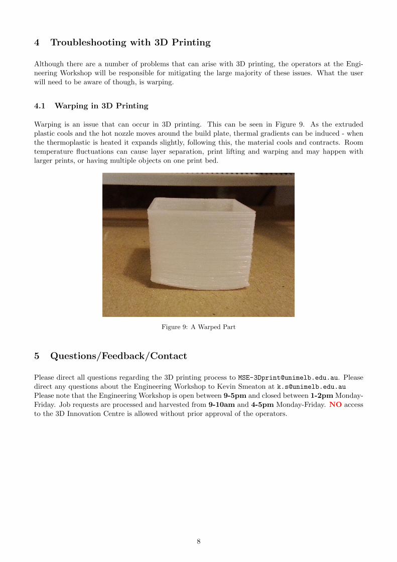
Warping is an issue that can occur in 3D printing. This can be seen in Figure 9. As the extrudedplastic cools and the hot nozzle moves around the build plate, thermal gradients can be induced - whenthe thermoplastic is heated it expands slightly, following this, the material cools and contracts. Roomtemperature fluctuations can cause layer separation, print lifting and warping and may happen withlarger prints, or having multiple objects on one print bed.
Figure 9: A Warped Part
5 Questions/Feedback/Contact
Please direct all questions regarding the 3D printing process to [email protected]. Pleasedirect any questions about the Engineering Workshop to Kevin Smeaton at [email protected] note that the Engineering Workshop is open between 9-5pm and closed between 1-2pm Monday-Friday. Job requests are processed and harvested from 9-10am and 4-5pm Monday-Friday. NO accessto the 3D Innovation Centre is allowed without prior approval of the operators.
8