36z owner's manual 10-7-10 -...
TRANSCRIPT

Note: This manual is published in accordance with ISO standard 10240:1995E Small Craft - Owner’s Manual
1
89 Pinckney Street, Boston MA 02114 Tel 617-723-3629 Fax 617-723-3629
March 2011
Dear 36z Owner: Congratulations on becoming Captain and Owner of the world’s best built and most fuel efficient yacht of its size. The enclosed copy of the 36z Owner’s Manual should further contribute to your enjoyment and proficiency afloat. This manual was created jointly with Zurn Yacht Design, Boston BoatWorks and MJM Yachts. Our experience with the 120 boats (40z’s 34z’s and 29z’s included) built to date has been incorporated to make this manual as useful and relevant as possible. Keep in mind there maybe some variances such as location of the breakers on the panel. And, from time-to-time we will change specifications to keep pace with changes made to improve the boat. When addressing a problem with a specific piece of equipment, this 36z Owner’s Manual is to be regarded only as a preliminary source of information. The equipment manufacturer’s own manual with trouble-shooting procedures, etc. is the primary source and authority. An ISO CE Mark “Owner’s Manual” accompanies, and forms part of, this MJM produced 36z Owner Manual. This booklet has many universal handling and operating tips worth reviewing. This Owner’s Manual is designed to be a living document, not only for builder updates but for your own use and record. Each boat is provided with a copy of the current Manual organized in a STAPLES “Mini-Ring” type binder that allows you to add pages as needed. One of the great advantages of purchasing a series-built or semi-custom design is that owners have the benefit of learning from one another. So, with your continued input and comments we can keep adding useful information and helpful hints to this manual. Part of the ISO CE Mark Certification Program is confirmation by the owner that the manual has been received. Please sign the extra page No. 3 included in the Manual as a receipt and return it in the stamped envelope provided. Best wishes for fair winds and sunny skies. On behalf of the builder and designer, we are most appreciative, and I am particularly honored, that you have chosen the 36z.
Robert L. Johnstone Chief Operating Member

Note: This manual is published in accordance with ISO standard 10240:1995E Small Craft - Owner’s Manual
2
Length Overall (Including Swim Platform and Bow Roller) 39.3 ft.
Length on Deck 36.0 ft.
Length Waterline 33.3 ft.
Beam 11.0 ft.
Hull Draft/Max Draft with Drives Down 1.5 ft/2.5”
Displacement (1/2 load) 13,100 lbs.
Fuel Tanks (combined) 200 gals.
Fresh Water Tank 100 gals.
Hot Water Tank 13 gals.
Holding Tank 25 gals.
Height over Water (w/ radar mounted directly on hard top) Approx 9.0’ ft.
Height over Road (w/ radar on trailer) Check, as will vary by trailer. Approx. 12.5 ft.
36z

2
Subject: BOAT INFORMATION BOAT MODEL: 36z Downeast HULL SERIAL # (HIN): EOU36z04K011 DESIGN PATENT: Patent No. US D475.338S (3Jun03) DELIVERY DATE: January 4, 2011_______ REGISTRATION #: ENGINES MAKE: Volvo-Penta MODEL: D3- 220A-3 DPS SERIAL #: 2003018715 and 716 Volvo 24 Hour Service 877-747-3682 or Joel Rumelhart 207-632-6868 DRIVES MAKE: Volvo-Penta # 3869465 MODEL: DPS-A-OXI Serial#: A152600 and 601 SKX TSK A149444 & 447 RATIO: 1:78:1 PROPELLERS MAKE: Volvo#3851494 BLADES: Duo Props – 4 Blade DIA./PITCH: F4 SS DuoProp ______ OTHER: MJM YACHTS, LLC CONTACT: Robert L. Johnstone PHONE: 617-723-3629 MA MOBILE: 401-862-4367 FAX: 617-723-3643 Email: [email protected] ADDRESS: 89 Pinckney St., Boston MA 02114 NAVAL ARCHITECT NAME: Doug Zurn FIRM: Zurn Yacht Design PHONE: 781-639-0678 ADDRESS: 89 Front St., Marblehead, MA 01945 LICENSED BUILDER NAME: Boston BoatWorks, LLC CONTACT: Scott R. S. Smith PHONE 617-561-9111 MOBILE 207-252-7190 FAX 617-561-9222 EMAIL [email protected] ADDRESS 256 Marginal St., Boston MA 02128 DEALER PHONE: ADDRESS: CE CERTIFICATION CERTIFICATE NO. BBBW003 (pending)

3
AUTHORITY: International Marine Certification Institute ADDRESS: Rue Abbe Cuypers 3
B-1040 Bruxelles, Belgique PHONE: +32-2-741-2418 WEBSITE: www.imci.org CLASSIFICATION: ISO CE Mark Design Category A Ocean (EC Directive 94/25/EC) for
craft designed for offshore voyages (1) where the vessel is correctly handled in the sense of good seamanship and operated at a speed appropriate to the prevailing sea state and (2) with significant wave heights above 4 m (calculations are based on 7 m) and wind speeds in excess of Beautort Force 8, but excluding abnormal conditions, e.g. hurricanes.
CAPACITY PERSONS: Maximum 12 Persons PERSONS/GEAR: Maximum Load -------------------------------------------------------------------------------------------------------------------------------------------- RECEIPT BY OWNER In compliance with ISO 10240:1995(E) the owner hereby certifies receipt of this manual and has read and agrees to the terms of the Builder’s Limited Warranty included herein.
Signature Printed Name Date Boat Name Hull # Address City, State, Zip Tel. Email NOTE: PLEASE SIGN ONE OF THE TWO COPIES OF THIS PAGE AND RETURN IT IN THE ATTACHED STAMPED ENVELOPE TO: MJM YACHTS at 89 Pinckney Street, Boston MA 02114.
Denotes an extreme intrinsic hazard exits which would result in high probability of death or irreparable injury if proper precautions are not taken.
Denotes a hazard exists which can result in injury or death if proper precautions
are not taken.
Denotes a reminder of safety practices or directs attention to unsafe practices which could result in personal injury or damage to the craft or components.

TABLE OF CONTENTS
4
CHAPTER 1 OPERATION 1.0 GENERAL 1.1 QUICK START GUIDE 1.2 OPERATING PROCEDURES 1.3 NAVIGATION 1.4 TOWING 1.5 HAULING OUT
CHAPTER 2 SAFETY EQUIPMENT
2.0 GENERAL 2.1 FUEL SHUT-OFFS 2.2 FIRE
CHAPTER 3 PROPULSION SYSTEM INTRO – TOP 10 REASONS of ENGINE FAILURE
3.0 GENERAL 3.1 NEW ENGINE BREAK IN 3.2 LUBRICATION 3.3 ZINCS 3.4 AIR INTAKES 3.5 EVC CONTROL PANEL 3.6 EVC DISPLAY 3.7 THROTTLE/SHIFT 3.8 STARTING 3.9 ALARMS 3.10 STOPPING 3.11 OPERATION
CHAPTER 4 STEERING SYSTEM
4.0 JOYSTICK DOCKING 4.1 HELM STATION 4.2 CONSOLE SWITCHES 4.3 POWER TRIM CONTROL 4.4 TRIM MODE OPTIONS 4.5 BOW THRUSTER (IF INSTALLED) 4.6 TRIM TABS 4.8 AUTOPILOT 4.9 WINDSHIELD WIPERS
CHAPTER 5 FUEL SYSTEM
5.0 GENERAL 5.1 FUEL SHUT OFFS 5.2 FILLING THE TANKS 5.3 RACOR FILTERS 5.4 FUEL CONSUMPTION & LOG
CHAPTER 6 ELECTRICAL SYSTEM
6.0 GENERAL 6.1 12 VOLT DC SYSTEM 6.2 120 VOLT 60 CYCLE AC SYSTEM 6.3 INVERTER/CHARGER 6.4 SHORE POWER 6.5 AC GENERATOR 6.6 REVERSE POLARITY 6.7 ELECTROLYSIS & CORROSION 6.8 BONDING 6.9 ELECTRICAL SAFETY 6.10 BREAKER & FUSE LOCATIONS 6.11 RAYMARINE FUSE LOCATIONS 6.12 INLINE & ANL FUSE LOCATIONS
CHAPTER 7 FRESHWATER SYSTEM 7.0 GENERAL 7.1 FILLING 7.2 USING & MAINTAINING 7.3 DOCK INLET 7.4 HOT WATER 7.5 WATER PURIFIER
CHAPTER 8 RAW WATER SYSTEM
8.0 GENERAL 8.1 ENGINE RAW WATER 8.2 ADDITIONAL RAW WATER USES
CHAPTER 9 SANITATION SYSTEM
9.1 VACUFLUSH CHAPTER 10 GRAY WATER SYSTEM
10.1 GENERAL 10.2 GRAY WATER TANK 10.3 BILGE PUMPS 10.4 HIGH WATER ALARM 10.5 COMMON DRAINS CHAPTER 11 OPTIONAL EQUIPMENT
11.0 OPEN 11.1 GENERAL 11.2 ANCHOR WINDLASS 11.3 PILOTHOUSE CURTAINS 11.4 PRIVACY/SUNSCREEN CURTAINS 11.5 REFRIGERATION 11.6 COOKTOP 11.7 MICROWAVE/OVEN 11.8 AIR-CONDITIONING 11.9 DIESEL HEATER 11.10 CLARION STEREO 11.11 SIRIUS SATELLITE SYSTEM 11.12 SAMSUNG TELEVISION 11.13 FLIR NIGHT VISION
CHAPTER 12 ROUTINE MAINTENANCE
VOLVO SCHEDULE ENGINE DIAGRAMS
CHAPTER 13 SEASONAL MAINTENANCE CHAPTER 14 FIGURES
14.0 SYSTEMS 14.14 TRUCKING CHECKLIST
CHAPTER 15 LIMITED WARRANTY CHAPTER 16 QUICK START

CHAPTER 1 OPERATION
5
1.1 GENERAL
This manual has been compiled to help you operate your yacht with safety and pleasure. It contains details of the yacht; the equipment supplied or fitted, its systems, and information on its operation and maintenance. Please read it carefully, and familiarize yourself with the yacht before using it. If this is your first yacht, or you are changing to a type of yacht you are not familiar with, for your own comfort and safety, please insure that you obtain handling and operating experience before assuming command of the yacht. Your dealer or yacht club will be pleased to advise you of local schools, or competent instructors. PLEASE KEEP THIS MANUAL IN A SECURE PLACE ON THE BOAT, AND HAND IT OVER TO THE NEW OWNER IF YOU EVER SELL THE CRAFT. This Owner’s Manual is not intended to be a course in boating safety, boat handling, navigation or general boating skills. It is the responsibility of the user to independently gain these skills. Instead, this manual will serve as a reference for matters specific to the 36z. Standard options are included in the manual with which your particular yacht may or may not be fitted. Custom options may be addressed in an addendum.
1.2 QUICK START GUIDE (See CHAPTER 16)
A separate “Quick Start Guide” is included that briefly reviews the key items to check before departure. Please review the topics in this manual before relying on the checklist – it is simply an “at-a-glance” sheet to insure that you don’t overlook anything important.
1.3 OPERATING PROCEDURES – ENGINE INSPECTION
To access the propulsion system, the cockpit engine hatch must be raised. The procedure is as follows:
Make sure personnel and equipment are clear of any moving parts before
operating.
- Turn ON house battery switch (located in top right of DC electrical panel) - Turn ON DC main disconnect breaker & engine hatch breaker at the DC panel - Activate the lift with the small black rubber toggle switch located in the starboard cockpit seat locker.
1.4 NAVIGATION
The optional builder installed navigation system includes autopilot w/compass, depth-sounder, chart-plotter, and radar. Modern marine electronics are a subject unto themselves and you should refer to the manuals that came with the equipment you purchased. However, here are a few points to consider: ! If you are unfamiliar with navigation, educate yourself before using the boat. Electronic
equipment is NOT a substitute for dead-reckoning navigation skills. ! It is not recommended to rely solely on electronic charts- bring paper chart back-ups. ! It is prudent to check (or have checked) your compass alignment once the boat is in your
primary area of operation. See the Ritchie instructions for compensation. ! Check that all equipment is functioning, even if you intend not to use it. ! Radar and its overlay projection on the plotter should be properly aligned (Double-check
when underway) See manual to adjust, tune and operate.

CHAPTER 1 OPERATION
6
Compass Heading & Calibration There are 3 heading references for navigation on the 36z: (1) The compass on the dash, (2) Autopilot digital compass, and (3) GPS COG (Course Over Ground). All of these headings should be within a degree or so of each other when underway. If not, it is recommended that differences be recorded on a deviation card after following the calibration method outlined below or employing the services of a compass adjuster. Use COG as the primary reference at a time when you are not influenced by wind/wave/tidal set. The digital compass sensor is located on a stringer outboard to port under the cabin sole. It is accessible by opening the cabin sole hatch and looking aft and to port. Avoid storing steel or iron items such as tools next to it. Ritchie Ship’s Compass Calibration Method 1) With the compass in its intended position, but not finally secured, select a course on your chart using two identifiable marks, buoys or landmarks that are within ten degrees (10°) of the north/south line. Try to select this course so that you can maneuver your boat "down range" of the marks selected. 2) From a position down range of the North/South marks, and keeping the marks lined up, run the boat visually along the northerly course selected. Turn the port/starboard compensator until the compass reads correctly. 3) Reversing direction, run the boat southerly, again keeping the marks lined up. If the compass is not correct at this time, there is an alignment error. To correct, rotate the compass itself to remove one half of this error. Repeat Steps 1 and 2 and then recheck this Step 3. 4) Simply repeat the procedures of Steps 1, 2 and 3, except this time, using an east/west course and the fore/aft compensator, although at this time any alignment error should have been eliminated. 5) Upon completing the procedure, secure the compass in its final position. Boat Speed Rather than a paddle-wheel or sonic device, the Raymarine C120 plotter is used to generate SOG (Speed Over Ground) that is displayed by the chart-plotter and may also be shown in larger digits on the Autopilot display. Eventually, you will learn to approximate boat speed through the water by relating it to RPM on the tachometer.
1.5 TOWING
Refer to the included ISO Owner’s Manual or to a book on seamanship and boat handling for towing guidelines.
1.6 HAULING OUT
A facility that is unfamiliar with the 36z may require information before hauling the boat with a Travel-Lift or crane & straps. Refer to the illustration included at the back of this manual. The keel (centerline of the boat) and chines (edges) should be used to position weight bearing supports. You will note that the fore and aft lift points are located approximately at either end of the pilot house... e.g. abeam of the windshield and the aft end of the hard top.
Point loading flat areas other than centerline and chine or setting the weight of
the hull on supports of insufficient area may result in damage to the hull.

CHAPTER 2 SAFETY EQUIPMENT
2.1 GENERAL
Spend time reviewing where your safety equipment is and how it functions BEFORE you need it. Remember, the best way to protect yourself and others from accidents is to eliminate potential causes of accidents before they occur. Good seamanship and common sense go a long way in this endeavor. [See Figure 14.1] Here is a safety checklist derived in part from the USCG Vessel Check List. State Regulations may vary: PFD’s A wearable USCG approved personal flotation device (life-jacket) must be provided for each person aboard. On the 36z, these can be types I, II, III or V. Also, one type IV throwable PFD must be immediately available for use. Children under 13 years of age are required to wear a USCG life jacket that fits when underway unless they are in an enclosed cabin or belowdecks. Visual Distress Signals (VDS) You must carry VDS’s aboard. If operating between sunset and sunrise, they must be suitable for night use and be within the age dates marked on the side of the flares. A minimum of 3 day/night use combination pyrotechnic flares are required. For a list of USCG approved devices, see the USCG recreational checklist. Fire Extinguisher In addition to the automatic fire suppression system fitted in the engine space, you are required to carry at least one type B-1 extinguisher aboard. This should be checked regularly. EPIRB If operating offshore, an EPIRB (electronic position indicating radio beacon) is recommended. Ships Papers & Registration You should carry the vessel’s registration papers and number plate. Pollution Regulation Plaques 5”x8” Oil Discharge Plaque and a 4”x9” Waste Discharge Placard should be fixed were visible. Charts & Light Lists Charts, light lists and a USCG required copy of the Inland “Rules of the Road” Navigation Rules Horn or Whistle Recommended to signal intentions or signal position. For instance, when in a narrow channel or the Intracoastal Waterway: To signal which side of another boat you will pass on, blow 1 blast if you are passing to their starboard side and 2 blasts if passing on their port side. Life Raft If you plan to be coastal cruising out of sight of land, it is prudent to carry a Coastal Life Raft which come in compact sizes that can be stored in one of the aft cockpit lockers. Heaving Line These floating lines are available and handy to have ready in case of emergency or to simply trail behind the boat when swimming, .with the end attached to one of the stern cleats. First Aid Kit Not a place to scrimp. It is advisable to carry a good, comprehensive, and well-organized (by injury) marine first-aid kit with manual. We recommend that it be stored in the head and that everyone onboard be informed of its location. (Remember, you may be the one in need of it!)

CHAPTER 2 SAFETY EQUIPMENT
2.2 FUEL SHUT-OFF VALVES
The fuel shut-off valves are located on top of the fuel tanks and are accessible through pilothouse settee lockers. Make sure you know how to shut off the fuel valve. (When the handle is perpendicular to the hose, the valve is closed.) In case of a fuel fire, STOP any machinery and close the valve to cut the supply of fuel to the fire/engine. If you should ever see fuel in the bilges, turn off the valve, clean the bilges, and find the source of the leak immediately. Also note that there are fuel shut off valves, normally left closed to designate one tank for each engine, on the lower inboard aft corner of the fuel tanks, which connect the two tanks together at the bottom for self leveling. There is only one fuel level sensor and that is on the starboard tank.
2.3 FIRE
Fire aboard a boat is a serious matter, and fire safety begins with fire prevention. You can reduce the risk of fire by following common sense guidelines:
! Do not allow debris or oily rags to collect in bilges or machinery spaces. ! Understand your electrical system, allow only qualified marine electricians to work on it, and shut
down as many circuits as practical when leaving the boat. Do not leave appliances running while unattended.
! Have your fire suppression equipment inspected regularly and learn how to use it. An automatic fire suppression system is installed on every boat in the engine and generator space. It is heat activated. Read the information that comes with the equipment. The system can also be manually activated at the helm station. [See Helm Console Section] Because a diesel engine would evacuate the suppression agent from the affected space, the system will shut down the engine (and generator) when it discharges. If manually activating the system, the engine should be shut down first. After the situation has stabilized, the shut-down feature can be over-ridden to restart the engine. A loud warning alarm will sound when the system has been activated. The hand-held fire extinguisher is rated to fight type A, B & C fires. To extinguish a fire, the most effective method is to cut the source of fuel to the fire. In the case of a diesel fuel fire, the fuel tank valves should be closed. In the case of an electrical fire, the main battery switches or main disconnect breakers should be turned off. Fire needs oxygen to burn, so if a fire should occur in an enclosed area, the best course of action may be to exit the area and seal it from the outside by closing all means of air inta

CHAPTER 3 PROPULSION SYSTEM
9
INTRO - THE TOP 9 CAUSES OF DIESEL ENGINE FAILURE (Motorboating Magazine - 2006). 1. NO FUEL: This is probably less of a problem on a fuel-efficient MJM than on other boats, but don’t think that it will never run out! Lack of owner attention to fuel consumption is the primary culprit for engine failure. A boat’s fuel tank can be nearly dry as a bone – even when the guage claims there’s a 1/8th of a tank left. Remember that at cruising speed, the gauge shows the tanks reading more than when the boat is at rest. A good rule of thumb is to never pass a fuel dock if your gauge is showing under 1/3 full. 1b. AIR IN FUEL LINE: If air gets drawn into the fuel lines because of either a small leak in a fuel line connection or the Racor Filter lid gasket/filter basket tabs have interfered with the lid being secured fully, you may find the engine will turn over, but won’t start. Check the Racor to insure the fuel level is within an inch of the top. Check the Volvo owner manual for the location of a manual primer pump. 2. DIRTY FUEL: Engine problems are caused by dirt and water in the fuel. Debris, stirred up from the bottom of the tank by wave action, is drawn into the fuel line and clogs the fuel filter element. Starved for fuel, the engine begins to run poorly, and then not at all. Moisture condenses out of the highly humid air on the inside walls of a fuel tank, then runs down into the fuel. Water can also be introduced at the fuel dock from a contaminated fuel supply. Fuel floats on top of water and the fuel pick ups are near the bottom of the tank. A fuel/water separator protects against this by handily extracting the water. Check the bowl daily and drain off the accumulated water. For severe contamination, use a fuel drying additive. 3. FUEL BUGS: Diesel engines suffer from microbial bugs growing in the fuel. If left unchecked, these critters clog filters. If you leave the same diesel fuel in the tank for any length of time, a fuel conditioner similar to that supplied with your boat by the builder will kill the bugs and break up any hydrocarbon residue into particles that will burn completely in the combustion process. 4. TIRED PUMP: As boats age, a worn-out circulating water pump is another engine killer. Impeller blades are commonly made of nitrile that stiffens over time and can break off entirely, reducing coolant flow. Periodic engine maintenance procedures can prevent this problem. A spare is provided in the Yanmar Spares Kit. 5. HARD HOSE: As water intake hoses age, they lose their resiliency and collapse under suction, causing a restriction in the flow of engine coolant. This results in over-heating. Prevention is easy: Visually inspect cooling hoses and squeeze them to be sure they retain shape and set. 6. CLOGGED INTAKE: Floating debris in the water is another culprit. Things like discarded plastic baggies, weeds, etc. can plug up the raw-water intake. You can avoid this problem by visually inspecting the strainer basket. When removing debris, be sure to properly replace the seal, otherwise the pump will either lose suction or spray salt water onto the air intake, depending on the strainer location. Smearing the seal with Vaseline or other marine-grade grease helps and firmly securing the top is important. 7. HARD KNOCKS: Collision with an underwater obstacle that damages the propulsion system. Often you can still operate the boat at low RPM to return to port, being careful to avoid excessive vibration that might otherwise compound the damage by damaging the transmission. The problem may be corrected in a day or so without hauling by an experienced diver who has access to a prop shop where the blades can be repaired and the prop re-balanced, then re-installed. 8. BAD BATTERY: Marine starting batteries die from old age and neglect. Keep the terminals and posts clean from that green corrosion that builds up, restricting the flow of current – preventing the cless from fully charging. Periodically have your batteries tested to determine their condition and expected longevity. The 36z is equipped with a “parallel” switch which can be turned on to employ the 400 ampere-hour house bank in starting the engine. 9. SAGGING BELT: As V-belts wear, they stretch and begin to slip. Consequently, alternators and water pumps don’t spin to their full speed. Batteries may not fully charge and coolant circulates sluggishly. The solution is to check belt tension regularly and tighten belts when necessary. Drive belts

CHAPTER 3 PROPULSION SYSTEM
10
can also snap. The only way to avoid this malady is to replace them once they begin to show wear. Spare belts are provided in the Volvo spares kit 3.0 PROPULSION SYSTEM (Optional Volvo-Penta Twin 220A-DPS Engines Shown) 3.1 GENERAL Your 36z is propelled by twin Volvo diesel engines turning duo-prop propellors. The dual-lever electronic control acts as a combination throttle and gear selector. Care should be taken when shifting. Always allow the transmission to engage the new gear before throttling up. If the two levers are set to within 200 RPM of one another, they will automatically synchronize.
The engine should never be running when swimmers are near the boat.
Engines are accessed by raising the cockpit hatch using the electric lift.
3.2 COOLING
Your engine passes seawater (raw water) through an intake in the sterndrive unit under the swim platform to the impeller (pump) then through the raw water intake strainter then through a heat exchanger where it cools the engine’s coolant. This coolant is circulated through the engine and returns to the heat exchanger. For the engine to keep cool, it must have an adequate supply of raw water and coolant.
RAW WATER INTAKE STRAINERS
ENGINE OIL DIPSTICKS
Unscrew Cap when engine cold to check COOLANT LEVEL
See Volvo D3 Operator’s Manual for greater detail of engine components
GEAR OIL LEVEL

CHAPTER 3 PROPULSION SYSTEM
11
If you get a high water temperature alarm, most likely the raw water strainer has become clogged. Check to be sure it’s clean first. Best to check the coolant level before embarking on your journey by opening the caps on top of the engine. Coolant should be visible (reach it with you finger when the engine isn’t hot) of the reservoir which is on top of the front starboard corner of the engines. Do not attempt to remove the coolant cap of a hot engine. For details on what type of coolant to use it is very important to, consult the Volvo-Penta operator manual. As the water and exhaust exit out the back of the drives, it is not as easy to check raw water flow. It is recommended to pay close attention to water temperature (167°-194° F is normal) at the outset. Engine oil temperature should be running at less than 220 degrees F. It’s a good idea to have a container of spare coolant aboard at all times.
3.2 NEW ENGINE BREAK-IN
While running the engine for the first time and after shut-down, check for proper engine oil pressure, diesel fuel leaks, engine oil leaks, coolant leaks, proper operation of the indicators and gauges, proper exhaust color, engine vibrations and sounds, If coolant or oil temperature is high (a) Is the raw water intake seacock open at the base of the IPS drives? (b) Are the raw water strainers clogged?
The engine may seize if it is operated when seawater intake is restricted or if load is applied without allowing the water temperature (engine) to warm up. During the first 10 hours of operation, full load should only be applied for short periods. Never run the engine for a long period at a constant RPM during this period. Higher oil consumption is typical at this time, so carefully observe oil pressure, oil temperature and coolant temperature, exhaust color and check engine oil and coolant levels frequently... ie daily.
3.3 LUBRICATION
Both the engine and transmission use oil for lubrication. The transmission will tend to use less oil than the engine, but both should be checked frequently. For the proper type of oils to use (which may depend on the service area and conditions) consult the engine manual. The engine oil may be checked on the port side of the engines by pulling up the red dipsticks, at least ! hour after running of the engines to allow the oil to drain down from the upper part of the engine. The transmission oil levels can be seen in the reservoirs on the transom.
3.4 CORROSION PROTECTION
Read the Volvo Operators Manual (VOM) carefully. In addition to a transom zinc, there are zincs on the sterndrive and engine. Pay close attention to these zincs, inspecting them with a diver at least monthly…a good frequency for cleaning the bottom of optimum performance as well. You’ll find that the timing for replacing zincs varies depending on the type of bottom paint used, the characteristics of the seawater, the amount of electrical current in marinas, or could indicate (if excessive wear is noted) an electrical short on the boat, etc. Inspect engine zincs periodically at the time of oil changes and remove the corroded area on the surface, replacing them when deteriorated to less than 50% of original size. Otherwise corrosion in the cooling system will occur and water leakage or parts breakage will result. Be sure to close raw water intakes at before removing a plug to replace a zinc.

CHAPTER 3 PROPULSION SYSTEM
12
Activates Control Panel. Push twice to Lock.
BACK button returns and steps up from sub-menus to main menu.
Push 1sec Backlight Off or On. Adjust with quick pushes. If pushed on inactive station, menu structure is activated.
2nd Station Lock Indicator See VOM 15
NEUTRAL BUTTON Push to Disengage Drives Green LED = In Nuetral No Light = Engaged
ENTER KNOB –Push in to acknowlege alarms, toggle menus, enter sub menus & confirm choices
Red = Active Station Flashing = Fault
Panel Selector – Not applicable with one Panel
3.5 ENGINE AIR INTAKES
Diesel engines use a large quantity of air for combustion. The engine of the 36z gets this air thru grills under the cockpit coaming, both port and starboard.
3.6 VOLVO PENTA EVC-C CONTROL PANEL
This allows the operator to perform settings and choose information displayed on the engine control LCD screen. See more detail in Volvo Operator’s Manual.
See VOM 16
3.7 EVC-C SYSTEM DISPLAY PANEL
This single display is used instead of traditional gauges. When the engine keys are turned ON to the first position detent (not hard right to START), the words “VOLVO PENTA EVC” will show briefly. This is the “C” version of the EVC Display, which means you can customize the info to be displayed in the main menu and it what form. The feature is called “My View”. See VPOM . ENGINE DATA (button 1) is programmed to show RPM, Coolant Temp, Fuel Level on the 1st page, then will show other info next time button is pushed such as Gallons Remaining, Gallons per Hour, etc. MULTI DATA (button 2) Shows operating info in 4 different windows. The user can choose the info to be displayed as numbers or analog, shifting between modes as button is repeatedly pushed.
1 2 3 4 5

CHAPTER 3 PROPULSION SYSTEM
13
TRIP/FUEL (button 3) Shows Trip Fuel Used, Average GPH on Trip, Hours on Trip and Engine Hours Total. Reset to “0” by pressing 3 seconds until beep heard. GRAPHS (button 4) - Values can be established for a range of 2 minutes to 8 hours. Port engine shown as black line and starboard as a gray line. CONTRAST & MENU (button 5) Push for 1 sec to set contrast to one of five levels by additional taps. Then EXIT. Press Button for 5 seconds to access configuration menu, then navigate using up and down arrows. Select with the right arrow. See VPOM page 20 for more information.
3.8 THROTTLE/SHIFT CONTROL
There 5 positions (front to back). FORWARD
IDLE FORWARD NEUTRAL
IDLE REVERSE REVERSE
The port and starboard engine RPMs will synchronize automatically when within 200 RPM of each other. Emergency Shifting If a fault occurs which prevents electronic gear shifting with the control levers, it is possible to shift manually using the procedure outlined in the VPOM.
SUDDEN MOVEMENT HAZARD This control lever governs both throttle and shifting functions. The boat may start to move abruptly when the marine gear is engaged: Ensure the boat is clear of all obstacles forward and aft. Cautiously shift to the IDLE FORWARD position then quickly back to NEUTRAL position. Observe whether the boat moves as you expect.
3.9 START ENGINE
Before starting the engine, make sure (1) the raw water intake seacock over the IPS drive flange is in the OPEN position (2) the raw water strainer is clean (3) the engine has sufficient oil and coolant (4) transmission fluid is at the proper level (5) there are no restrictions to the air intake grills (6) the fuel valve over the starboard tank is OPEN (8) the HOUSE and BOTH ENGINE battery banks (under the electrical panel) are turned ON (9) the throttle is in the neutral position showing the “N” Green Light on the EVC Control Panel (9) no one is in the water near the boat and (10) all machinery space hatches are closed. TURN ON ENGINE Turn the spring-loaded Ignition Keys clockwise to the first detent a position I. The LCD screen will momentarily show “Volvo Penta EVC”. A long continuous beep indicates that the self-test function has failed. Ignore the top “key” symbol on the EVC panel which is only activated for dual helm station boats. START ENGINES by holding one then the second Ignition Key to the right with pressure to the to position III on the outer key rim, for several seconds until the engine starts. Then release the key,

CHAPTER 3 PROPULSION SYSTEM
14
so it springs back to position I. The engine will not start unless the shift levers are in NEUTRAL. If repeated start attempts are needed, the key must be turned back to position 0 first.
Never engage the starter motor (turning key hard to the right) while the engine is running. This may damage the pinion and/or ring gear. IF BATTERY VOLTAGE is low and you have difficulty turning over the engine, a momentary Parallel Switch is located to the left of two Engine Start Battery Switches underneath the electrical panel belowdecks. By turning this switch on, you add the capacity of the house bank to the start battery. Once started, turn OF the Parallel Switch. It is for emergency use only. TO REV THE ENGINES out of gear. Push the “N” button on the EVC Control Panel until. The green light over “N” flashes to acknowledge shift is disengaged. To disengage the Neutral function for normal operation. Push “N” button. A steady green light acknowleges. Never race the engine when it is cold.
3.10 ALARM DISPLAY
When the ignition key is first turned ON to position I, you may hear an audible alarm signal and see a “Stop Sign” appear on the EVC Display, indicating that the diagnostic function has registered a malfunction. PRESS the center knob once on the EVC Display to acknowledge the alarm. When the fault has been acknowledged, the audible warning will become silent and the source of the problem indicated on the display. Please refer to Volvo Operator’s Manual chapters for detailed information about FAULTS and recommended action starting on page 40 of the VPOM.
3.11 STOP ENGINE
Put both engine controls in NEUTRAL. Turn & hold the spring-loaded Ignition Key with pressure to the left to position S until the engine stops. If unsuccessful, there’s a clearly labeled “Emergency Shutdown” button in the upper middle port side of the engine. Make sure to turn OFF Engine Battery Switches under the electrical panel when leaving the boat. Engine Stop & Restart after Crash-Stop If the engine otherwise stops, the following procedure for re-start must be followed. 1. Put control lever in NEUTRAL 2. Acknowledge any ALARM by pressing the center KNOB on the EVC Panel. 3. TURN & HOLD ignition switch left to OFF until all lamps have gone out. 4. Then TURN the ignition system to the ON (not the engine Start) position only. 5. Acknowledge any ALARM by pressing the center KNOB on the EVC Panel. 6. START the engine by: TURNING & HOLDING the ignition switch to the right. 7. STOP the engine. Wait again until all lamps have gone out. 8. RESTART the Engine.
3.12 OPERATION
Engine trouble can arise if the engine is operated for a long time under overloaded conditions at max RPM. Recommended “Max Cruising Speed” is at least 10% below full throttle of 3400-3600 RPM. While running, pay attention to the engine gauges on the LCD display. A significant change in temperature, oil pressure, or voltage should be investigated immediately, before the engine is damaged. OIL PRESSURE – Normally between 4.5 and 5 bars, except lower when idling

CHAPTER 3 PROPULSION SYSTEM
15
COOLANT TEMPERATURE – Normally between 167 and 194 degrees F. 36z #4 runs at about 181 degrees at 25 knots OIL TEMPERATURE – This should be less than 220 degrees F, or 105 degrees Celsius. CHARGING – Normally about 14 Volts when underway. Depending on hull structure and engine installation, engine and hull resonance may be greater at some speeds than others. This is normal and you will learn to pick the sweet spots. If you hear any abnormal sounds, stop the engine and inspect.
If any warning lights or buzzers activate, stop the engine immediately. Determine the cause and repair the problem before continuing to operate.

CHAPTER 4 STEERING CONTROL SYSTEM
4.0 STEERING SYSTEM
The 36z has an integrated, electronically controlled power steering system, which through electric motors rotate the two sterndrive units mounted on the transom. When running, the 36z is steered as with outboards. Thrust of the propellers is directed more immediately and precisely from side to side through a 26° arc to steer the boat.... rather than bouncing the prop wash pf a conventional straight shaft propulsion unit off a rudder. When the throttle/shift levers are put in (N) neutral and the left-hand button pushed to activate the joystick: Control of the pod drives is transferred from the throttle/shift levers to the joystick that controls the steering computer. When the joystick is activated, the steering wheel is inoperative. Emergency Alignment If a fault occurs which prevents one or both of the sterndrives from being operated with the steering wheel, it is possible to align the faulty propulsion unit(s) so that its aimed straight ahead (and won’t act like a rudder), so as not to impair operation of either the remaining propulsion unit or the steering of the boat with the two engines. See the VPOM. Emergency Steering These controls are attached to the engine with cables, so if the electronic steering ever failed on both propulsion units, a steering method using the two engines can be employed. This is outlined in the VPOM. Emergency Shifting In an emergency, you should be able to shift the drives manually. There is a shift actuator that normally shifts the mechanical drive, if that is not functioning, you can remove the cable from the shift actuator and manual push/pull the cable to shift into gear.
4.1 JOYSTICK DOCKING CONTROL
This control is used only for docking and maneuvering at slow speed. Learn to handle the joystick in a safe and correct manner before you start using the function in tight quarters.
When the joystick is active, the normal engine controls are Neutral and inactive. A computer operates the drives and shifting. Rotation of the wheel is frozen and it should not be turned, as damage may occur.
To Activate: Both engines must be running and the engine control handles must be IN NEUTRAL. Press the left (L) button. A beep confirms it is active and the light above will go on. To DeActivate: Either move the engine controls OUT OF NEUTRAL (forward or reverse) or press the left (L) button again. A double beep will confirm that it is OFF. Boost Function In windy weather or current when you need more oomph, push the right (R) button. A beep will confirm it’s engaged. Deactivate by pushing the button again. The light above will go on and you’ll hear double-beep confirmation. Maneuvering with Joystick Follow the arrows. Lean the joystick post in the direction you’d like to go. Release and the thrust stops. The boat may keep moving, so you may have to tap it in the opposite direction to stop it. The top of the joystick is rotated (twisted) to orient the bow and stern, or to spin the boat completely around on its own axis. Pretty simple Takes some practice until it becomes completely intuitive.
R L

CHAPTER 4 STEERING CONTROL SYSTEM
EVC Display Panel
EVC Control Panel
Volvo Joystick
FLIR Infrared Night Vision Cnntrols
Bilge Pumps (3)
Throttle/Shift Levers
Genset Panel
Spotlight
C140W GPS Plotter/Radar
Engine Start/Stop
ST 60 Depth
Trim Tabs
FireBoy System
Bilge Water Alarm 4”
AutoPilot
Sterndrive Raise/Lower
Windlass Up/Down
12V Cellphone Outlet
Engines Start/Stop
Switches (below)
Joystick Calibration When moving the boat sideways if it seems that the bow or stern moves more than the other, see the Volvo Penta Operator’s Manual to make adjustments.
4.2 HELM STATION
The helm station console is where most of the operational controls of the boat are located. Become familiar with these before you need to use them. In addition, make sure that when you are using the boat, even if you are not using a specific piece of equipment, that the circuit breakers are on for any equipment you might need.
4.3 CONSOLE SWITCH PANEL

CHAPTER 4 STEERING CONTROL SYSTEM
NAV LTS FWD Underway AFT At Anchor
WIPER WASHERS Read Instr Booklet.
Press to Sound HORN
Press when Raising Rode, Chain & Anchor to Wash with Fresh Water
With the exception of the Anchor Washdown which is activated along with the “Windlass” breaker (and must have the “Water Pressure” switch ON as does the washer function of the “Wiper” switch) funcitons of this panel on the console are activated by turning on their respective breaker switches on the DC Electrical Panel in the main saloon. Functions of the panel rocker switches are described below the corresponding switch:
4.4 POWER TRIM CONTROL PANEL
Activate by turning on the ignition. The current position (angle) of the drivea can be shown on the EVC Display. To move both drives simultaneously, RAISE the Bow (and to lift the drive up) PRESS the central “Up Arrow”. To LOWER the Bow ( and lower the drive) PRESS the central “Down Arrow”. To move just one drive at a time, such as raising one drive up to reduce drag while operating just a single drive, use the small black buttons on either side, instead of the central arrows. Emergency Trimming. If a fault prevents the trim panel from working, PRESS & HOLD the BACK button (--) on the EVC Control Panel then trim the drive using the Trim Panel. This action over-rides preset automatic trim limits.
4.5 FOUR TRIM MODES

CHAPTER 4 STEERING CONTROL SYSTEM
Automatic Power Trim Assistant (PTA) Ranges – The trim range is adjusted automatically according to RPM. When a preset RPM level is reached, the drive is angled automatically to the trim angle specified. In addition to “idle”, 4 trim angles can be selected at different RPM levels to attain optimum comfort/performance. The PTA must be activated for this procedure. One example of PTA RPM breakpoint/power trim settings is shown below: Idle -3 1500 -3 2500 -2 3000 0 3600 0 The PTA is turned ON or OFF in the EVC Display menu under “Settings/sub-menu PTA”. Port side is the “master” for a single engine. The function must be turned “Off” before hauling the boat out of the water to prevent any auto trimming if any test are performed with the boat on land. Manual Over-ride. When the PTA is activated and the driver desires a drive angle other than the presets, use of the Trim Panel buttons momentarily deactivates the PTA until one of the preset RPM levels is passed. Automatic mode then resumes. To determine the best trim angle and ranges, familiarize yourself with the characteristics of the boat, recording the RPMs and trim position at various speeds and in various wave conditions. Beach Range – Used for running in shallow water at reduced speed of not greater than 1500 rpm. Make sure the drive’s raw water intake is never trimmed out of the water.
Lift Range – When the drive is tilted to maximum height, but not when running, for trailing. Power trim has an automatic stop that cuts power when the preset end limit has been reached. The stop is reset automatically when activating down trimming. Never run the engine when the drive is in “Lift Range”.
Auto Kick Up – Releases the drive if hits bottom or an object in the water. This feature only protects the drive when going forward. There’s no protection in reverse. If the function has been tripped and drive released, it must be trimmed back to the original position using the control buttons.
Check after any contact that the dirve or
propeller are not damaged, or if there are vibrations from the drive. If this is the case, then the boat (if possible) can be run at slow speed to harbor to haul and inspect. Or turn off the and raise the damaged drive and run on the good drive. Check the oil level in the drive. If colored gray, water has entered. If this is the case or other damage exists, contact an authorized Volvo Penta workshop. If only the propeller is damaged, it must be replaced then the boat run to be sure there is no other damage.
4.6 BOW-THRUSTER (Optional) Normally, with the joystick control, one does not need a bow thruster. If one elects not to install the joystick control system, then the boat can be operated like a conventional twin screw sterndrive. In which case the bpw thruster can be used to greatly increase the maneuverability of the boat at slow speeds in tight quarters around docks and slips.

CHAPTER 4 STEERING CONTROL SYSTEM
Passengers on the foredeck are at risk if the bow thruster is engaged without their prior knowledge.
Consult the user’s manual for specifics about your thruster. In general, thrusters are best used in short bursts. Prolonged use may damage the motor, or at least trip the breaker. When not in a situation where the thruster may be necessary, leave it turned OFF to avoid damage. Consider the fact that your thruster gets DC power from the engine start battery, which is charged by the engine’s alternator. If the engine is not running, has not warmed up for 7-8 minutes to the point that the alternator is charging the start battery, or running at idle, the thruster can consume more energy than the alternator can provide. It is possible to discharge the battery or burn out a thruster motor by over-use of the thruster. The thruster automatically turns OFF after 6 minutes with no use.
Turn on the thruster(s) by holding down the two left buttons (or turning the switch to ON with some models) until the activation light appears. (You will hear the breaker click) If the light does not appear, check to see that the large red knob for the bow-thruster circuit breaker (below ignition panel) is pulled out.
When operating the thrusters, allow a second or two for the propeller to come to complete stop before reversing direction to avoid damage to either the prop or internal coupling sheer pins (Extras in holder on motor housing under accessed through seat or berth forward hatch..
Thruster zincs should be checked periodically and replaced if significantly worn.
4.7 TRIM TABS
At low or high speeds, it’s not necessary to trim the bow up or down, but you may need tab applied to level the boat from side to side due to loading or to counteract wind pressure. The boat leans into a breeze. Tabs are useful for lowering the bow for better visibility or for slicing through waves to avoid pounding. At higher speeds when the boat naturally runs flatter and when running downsea into the back of waves, it’s advisable to raise the bow for dry running and control, allowing the bow to lift. The trim tab breaker on the DC panel must be ON. The trim tab control buttons are wired intuitively (the lights indicate which side is going up or down) By pushing down the starboard arrow, the bow leans down to starboard and the lights go up on the port side. (What’s actually happening under the boat is,the port tab is going down to apply pressure to lift the port aft corner and side of the boat).
4.8 AUTOPILOT (Optional)
The Electronics breaker (on the DC panel) must be ON for the autopilot to function. Check the autopilot display and note the rudder angle indicator which helps in maneuvering the boat. When the compass heading is displayed on the autopilot it is operational and can be activated by pushing AUTO. The boat will then maintain the displayed heading. Push +1 or -1 for one degree course corrections or +10 or –10 for ten degree increments. When not activated, the Autopilot display maybe configured to show BOATSPEED (SOG from the GPS). See the Raymarine manual. The Autopilot has been calibrated specifically for 36z operation. If you notice “hunting” rather than steady course keeping, see the Raymarine Manual to check Configuration parameters applied to your device or Contact Erik Rochelle at Boston BoatWorka.

CHAPTER 4 STEERING CONTROL SYSTEM
4.9 WINDSHIELD WIPERS The 36z is fitted with two windshield wipers. For specific instructions, refer to the user manual.
The wash feature is connected to your boat’s freshwater system and requires that the system be pressurized (i.e. that the freshwater pump is ON). If the wipers are to be used in sub-freezing temperatures, a separate system must be installed which utilizes anti-freeze.
4.10 HELM POSITION TEAK RISER (Optional)
This removable teak & thiokol (to match teak decking) riser raises the level of the helm station sole by 4” to improve visibility over the bow for anyone under 6’2”. This nicely crafted piece of teak simply lifts out and may be stored in one of the pilothouse settee lockers when not in use.
4.11 LOSS OF STEERING NOTE! The following procedures only apply if the boat is equipped with electronic or joystick steering. WARNING! When steering wheel control is lost, engine speed is automatically limited.
WARNING! Do not shut off engines when docking or when you need to maneuver the boat.
When you shut off the engines, the drives will center and stay centered as long as the engine is off. If you are still in motion when this occurs, you will not have steering control and the boat will move straight forward until coming to a standstill. Both Engines Stop Running There are several reasons that both engines would stop running. If the emergency stop switch is pushed, both engines will stop operating. Running out of fuel will also cause the engines to stop functioning. Another possibility is that the propellers become fouled (e.g. anchor line, tow rope, etc.) and cause the engine to stop. One Engine Stops Running In some instances, only one engine may stop functioning or you may want to turn off one engine due concern with oil temperature in one engine, the props on one side are damaged, or to simply run the boat on one engine. The propeller(s) on one drive may become fouled (e.g. anchor line, tow rope, etc.) and cause the engine to stop running. Other possibilities include engine failure, ignition key turned off, and so on. CAUTION! When one engine stops running, oil pressure needed to control steering for that drive side will be lost. While the functioning side will still provide steerage, control characteristics for the boat will be substantially different from that of two running engines. Running on One Engine When using only one engine, the drive on the non- working side should be tilted up. To tilt up the nonworking drive: 1. Turn ignition key on the non-working side to the START position (key on, engine off). 2. Using the small black trim/tilt button on the side of the engine…not the large central tilt arrows…, tilt the drive UP as far as it will go. 3. Turn ignition key OFF. CAUTION! Failure to lift the drive with steering faults may cause the drives to hit one another, potentially causing extensive damage to drives and engines.

CHAPTER 5 FUEL SYSTEM
22
5.0 GENERAL
It is important to understand the fuel system aboard your boat. Diesel fuel is different than gasoline. In most respects it is safer, however precautions need to be taken to maintain the safety of your boat. Please study the safety precautions in the NMMA publication “Sportfish, Cruisers, Yachts – Owner’s Manual.” Diesel engines need to intake more fuel than they burn, and so they differ from gasoline engines in that they return excess fuel to the tank. Both feed & return of port and starboard engines are their respective 175 gallon fuel tanks. The two fuel tanks are connected at the bottom by a “compensating” fuel line with isolating shut-off valves at both aft inboard corners.
5.1 FUEL SHUT-OFF VALVES
These valves are located on top of the fuel tanks aft and are accessed through pilothouse seat lockers. In the photos below they are shown in the open postion, parallel with the fuel lines.
These valves should be shut down if inspecting a Racor filter, in an emergency or in case of a fire in the engine compartment.
A fuel line connects the two fuel tanks with shut off valves in the lower, inboard aft corners of the two tanks, underneath the mesh organizer bags in pilothouse settee lockers. The port valve is shown in this picture. Generally, It’s a good idea to keep these closed, allowing each engine to draw from its own tank and to make filling the tanks easier. With valves closed, fuel tanks can also be used to correct static trim. If you have more gear stored on one side of the boat than the other, add less fuel to the heavier side.to equalize.
STARBOARD TANK showing fuel shut-off , VacuFlush Tank & Pump and Raymarine Autopilot Interface Box
PORT TANK showing fuel shut-off for port engine as well as AC Compressor.

CHAPTER 5 FUEL SYSTEM
23
5.2 FILLING THE TANKS Deck fills are mounted on the side decks, port & starboard, and are labeled “DIESEL.” Each one services only its respective tank, although with the connecting fuel line valve open, you will get some transfer to the opposite tank. As the tank is filled, vapor escapes the tank thru the vent. Overflow is prevented by an in-line fuel/air separator that will not allow fuel to pass.
should be taken while filling. Check the fuel level gauges and listen for the rise in pitch at the deck fill, as fuel reaches the top. Shut off the nozzle immediately. Do not attempt to “top off” the tanks. Have an absorbent cloth handy to prevent any overboard spillage. Variations in temperature as well as trim angle could cause overflow or vent-line blockage.
5.3 RACOR PRIMARY FUEL FILTERS
Racor Filters are your first line of defense against bad fuel and are installed on the bulkhead just forward of the engines and accessed by opening the aft seat engine hatch. Check these filters regularly for any accumulation of water or contamination. Water will appear as a dirty gray, cloudy substance in the clear bowl. You should be able to see thru the pink fuel in the bowl at all times. Also, you should not see bubbles passing through the filter while running. This would indicate a leak on the suction side of the fuel system.
5.4 FUEL CONSUMPTION
The chart below is prepared from the first seatrial in Boston Harbor, September 2010. Fuel efficiency is expected to improve marginally as the engine breaks in.
Range of Efficient Operation It’s interesting to note that it doesn’t matter whether you are going 11 knots or 30 knots on a 36z, nautical miles per gallon remain fairly constant. Cruising Speed Volvo Penta suggest that given suitable conditions, 10% below wide open throttle, or about 3600 RPM at close to knots is an acceptable cruising speed.
CLEAR GLASS INSPECTION BOWL
FILTER ACCESS LID – Be sure to close fuel shut-off valve before opening. Be careful to seal properly without pinching gasket.
WATER DRAIN PETCOCK – If water seen in bowl, hold a paper cup under the petcock and drain until clear fuel seen.
FUEL LINES from tank and to engine

CHAPTER 5 FUEL SYSTEM
24
FUEL EFFICIENCY RANGE
RPM GPH KTS NMPG NMrng* 700 .5 5.1 10.7 1928
1000 1.0 6.6 6.9 1242 1500 2.7 9.1 3.3 595 2000 5.6 12.3 2.2 396 2500 8.4 17.4 2.1 378 3000 11.8 23.4 2.0 360 3200 13.3 25.7 1.9 342 3400 15.1 27.7 1.8 324 3600 16.9 29.7 1.8 324 3800 19.6 31.0 1.6 288 4020 24.0 35.0 1.5 270
*Range based on 90% of 200 gallon
capacity
Remember that fuel level readings when underway, with the fuel pushing back in the tank where the fuel level sensor is located, could be reading " tank more than what’s really there. So, when you get down to 1/3 tank, it’s time to top off.... not roll the dice on finding another fuel dock open later in the day.

CHAPTER 5 FUEL SYSTEM
25
36z FUEL CONSUMPTION LOG
Engine Hours Consumption Date Marina/Fuel
Dock Current Since
Last Fill Diesel (Gals)
Gals/Hours
COMMENTS
CHAPTER 6 ELECTRICAL SYSTEM
26
6.0 GENERAL
The 36z’s electrical system may be more advanced than what you are accustomed to as it combines DC and AC power in several ways. Most of the electrical components on your boat use 12 volt DC power from 4-5 batteries totaling nearly 700 Ampere Hours of capacity. This battery capacity is recharged in 3 ways:(1) Alternator output from the engines when running; (2) From 110V 60cyle AC shorepower through the Mastervolt Charger or (3) From the Northern Lights Generator which outputs 110V 60 cycle power to the charger. 120 volt AC power, typically found in homes, is supplied to the boat in 3 ways: (1) via 1 or 2 shore-power cords plugged into a shoreside receptacle (2) by an optional generator or (3) by inverting DC power from a battery into AC power through the Mastervolt Inverter. The AC components aboard your boat include the cooktop, microwave, some TV components, the air-conditioning, water heater, inverter, and receptacles (to plug in your own AC equipment).
Both AC and DC electrical power sources are potentially dangerous. Do not attempt to work on any part of your boat’s electrical system if you are not a qualified marine electrician.
6.1 12 VOLT DC
There are two battery banks on your boat. The house bank consists of (2) 200Ah, absorbed-glass mat (D4 AGM) batteries. The engine bank consists of two 105Ah Group 31 AGM start batteries which are also used to run the windlass. Whenever a charging source is present (either from the battery charger or an engine-driven alternator) both banks are automatically charged. AGM batteries are essentially no-maintenance.
Do not attempt to open the batteries. Other than keeping them properly charged, stored, and clean (especially between the terminals), there is virtually nothing you need to do to them. The battery charger is factory set specifically for AGMs. If the engine is not running, the batteries can be charged via the battery charger, which is powered by AC electricity either from your generator or shore-power. It is important to read and understand the inverter/charger manual to be sure that the unit is functioning as you expect.
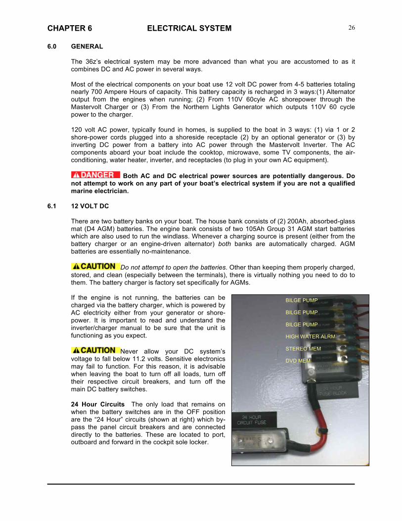
Never allow your DC system’s voltage to fall below 11.2 volts. Sensitive electronics may fail to function. For this reason, it is advisable when leaving the boat to turn off all loads, turn off their respective circuit breakers, and turn off the main DC battery switches. 24 Hour Circuits The only load that remains on when the battery switches are in the OFF position are the “24 Hour” circuits (shown at right) which by-pass the panel circuit breakers and are connected directly to the batteries. These are located to port, outboard and forward in the cockpit sole locker.
BILGE PUMP BILGE PUMP BILGE PUMP HIGH WATER ALRM STEREO MEM DVD MEM

CHAPTER 6 ELECTRICAL SYSTEM
27
House and Generator battery switches These rocker switches with sliding cover are located on the upper right side of the DC panel with a Battery Combiner between. When the battery combiner switch is pushed DOWN, it is OFF. Pushed in UP it is ON. It is recommended to leave it in the middle AUTO position where it stays active at over 13.6 volts and deactivates below 12.7 volts. DC Breaker Panel This custom MJM panel Includes digital readouts for voltage and amperage drain of the House Bank in Position 1 of the display and reads condition of the generator battery in Position 2.
To use DC components, the HOUSE battery bank switch must be ON, the top main DC disconnect breaker on the panel must be ON, and the component’s respective breaker must be ON. Windlass Operation The windlasss uses Engine Batteries, so it is necessary to have the Engine Battery switches turned ON and ideally have the engines operating when using the windlass. The GENERATOR battery switch must remain on when running. Engine Battery Switches The two Engine Battery Switches are located on the top right corner of the AC Panel. To start the engines or use the windlass, the engine START battery switches must remain ON. The Combiner switch between, manually in the UP position combines the two engine start batteries should one of them fail. The DOWN position is OFF and the MIDDLE position is AUTOMATIC combining of the two engine batteries and also the house bank if voltage is under 12.7 volts…deactivating when over 13.7 volts.
6.2 120 VOLT 60 CYCLE AC Breaker Panel The main AC disconnect breakers for AC #1 and AC #2 are located in the middle of the AC Panel. They must be ON for shore-power to supply the boat’s AC power. AC Shore 1 (left half) includes breakers for those items which can be handled by the Mastervolt Inverter. To use the inverter, (1) the house battery selector switch must be ON and (2) the inverter breaker on the AC panel must be ON. Refer to the inverter/charger manual for more information. When the Shore 1 shore-power cable is attached and the Shore 1 select breaker is ON, Shore 1 will supply AC power to AC Panel #1 (forward side of panel). With the inverter ON, the shore-power will override it and the inverter will automatically go into stand-by mode. Freshwater Tank Level Guage

CHAPTER 6 ELECTRICAL SYSTEM
28
The AC Transfer switch allows either Shore 1 or generator to power the AC Panel #2 circuits. If this function is utilized, be aware that using too many AC appliances at once will cause a shorepower breaker to blow. AC Panel Shore 2 (aft or right half of panel) is designed for those items having too much load for the batteries and inverter, thus requiring either shorepower or the generator to supply AC power. The high amperage water heater and air-conditioning systems are best supplied with a shorepower cord to stern INLET #2 which by-passes the inverter and goes right to AC Panel #2. However, they can also be powered from shorepower Inlet #1 using the TRANSFER feature of the panel so long as one doesn’t try to use the Microwave and/or Cooktop or both the Water Heater and AC at the same time. CHARGING The main HOUSE battery switch can be switched OFF when the boat is not used, and the batteries will still accept a charge from 120V SHOREPOWER through the battery charger. Obviously, to keep the Refrigerator going, you’d have to leave the main HOUSE battery switch ON as well as the Refrigeration breaker switch ON. Leave “Inverter/Charger” breaker ON at AC Panel 1. Note green LCD “Charged” on Link 2000 must be ON. “Invert” LED light must be OFF. If you are leaving the boat plugged into shore-power and you wish to turn off all DC loads but still be able charge batteries. Leave the house switch ON and turn off the top Main DC disconnect breaker on the DC panel.
Disconnecting shore power with INVERT LED left ON may cause discharge of the house battery bank.
6.3 INVERTER/CHARGER
The 36z uses the Xantrex Freedom SW 3000 watt combination inverter/charger (in a single unit). This remote panel has its own manual, with which you should become familiar or it may be down-loaded from www.xantrex.com . This unit is located over the starboard fuel tank in the pilothouse settee locker. When a supply of AC power is present (from shore-power or generator), the unit can charge both the house battery bank, generator and the engine start batteries. The Inverter/Charger breaker (on the AC panel) should normally be ON. If no source of AC power is available, the inverter can use DC power from the house bank to create AC power for items on AC Panel #1. If AC power becomes available, either from shore-power or the generator, the inverter/charger transfers this power to AC panel #1. In other words, your batteries will not be used to create AC power if either the generator or shore-power #1 is active and the inverter breaker is ON.
If not functioning , here’s ON/OFF switch and RESET button location

CHAPTER 6 ELECTRICAL SYSTEM
29
INVERTING To use AC power when no generator or shore-power is available, make sure the inverter breaker is ON. Be sure the Xantrex display shows it to be in the default Operating mode and not Safe mode used when adding or removing devices to disable all charging and inverting functions even stopping the generator if its running. To return to operating mode, select Operating from the System Settings menu under Desired Mode then push Enter. To enable inverting on the Xantrex remote panel, scroll down to Inverter using the up/down arrows, then push the Enter button. A light will come on to confirm that AC power is now being supplied to the forward AC Panel #1, which includes those items which may be run from the inverter alone…although not necessarily all at the same time for very long. The inverter can only be powered by the house bank, but can monitor both the house and engine start banks. When finished using AC power through the inverter push Exit to turn off.
CHARGING To activate the charger when SHORE POWER is applied to AC Panel #1 or when GENERATOR is on: Scroll to Charger then push Enter.
CAUTION: DO NOT LEAVE THE BOAT WITH THE INVERT SWITCH “ON” AT THE XANTREX ALONG WITH THE INVERTER/CHARGE SWITCH “ON” ON THE AC PANEL IF YOU ARE NOT INVERTING AS THIS MAY DRAW 10-12 AMPS EVEN IF NO AC DEVICE IS TURNED ON. OR, SEVERAL DAYS LATER YOU MAY END UP WITH DEAD BATTERIES (All of them if the Parallel Switch is “On” too.)
6.4 AC SHOREPOWER
The first of three ways to supply AC power to boat appliances/systems is through Shorepower #1 and #2 30A 125V connections in the transom. These are shown Left to Right with the 3rd Inlet for a TV cable hook-up The cover lid springs open by pushing in at the bottom, If two 30A 125V sockets are not available on the dock,
very often you will find a 50A 225V socket to which you can connect a “Y” pigtail (West Marine 410373). If you overload, an AC circuit, one of two AC shorepower breakers may trip. To reset, locate the shorepower breaker box (shown at right) in the aft starboard corner of cockpit locker. Be sure both switches are ON. Hot Water If a second shore-power receptacle is not available and you have not operated the boat recently, there won’t be any hot water from the engine’s heat exchanger. Simply shift the single cord from the Shore 1

CHAPTER 6 ELECTRICAL SYSTEM
30
receptacle aft to the Shore 2, flick the Hot Water breaker on, wait 15 minutes and your shower will be ready.
6.5 AC GENERATOR (Optional)
The generator, used to create AC electrical power, is located in the cockpit sole locker amidships. To operate, The generator battery selector switch at the top of the DC Panel must be ON and the generator must be selected on the AC panel.
Pre-Start Checks [refer to labeled diagram that follows) (1) Check that cooling water is 1” below filler cap (2) Check the oil at dipstick (3) Open fuel line lever over starboard fuel tank. (4) Close the raw water seacock, check & clean sea strainer & reopen the seacock (port locker) (5) Reach behind the Generator Control Box [13] and be sure that the AC Circuit Breaker and AVR Circuit Breaker are both in the “Up” position (5) Turn ON battery switch for Generator. Note the battery switch must always be kept ON while the generator is running. If the switch is turned OFF with genset running, the battery charging regulator could be ruined. (6) Turn OFF all AC Panel 1&2 switches/breakers, including Generator double-handled switches on top of AC Panels 1 & 2 and AC Breakers below.
PREHEAT: On the Control Panel, ;depress PREHEAT switch ON for 10-20 seconds to activate control system
START: Then, depress START switch while continuing to depress PREHEAT switch. When generator starts, release both switches. Do not crank for more than 20 seconds at a time. Allow the generator to run for about 15 seconds until LED green light appears next to “Generator” on AC 1 Panel below

CHAPTER 6 ELECTRICAL SYSTEM
31
(forward most) indicating that the panel is receiving electric current. ACTIVATE AC PANEL 1: When the green LED light appears on AC 1 Panel, turn ON double Generator Selector switch for AC 1 ONLY. There is a delay until Volts (about 115) register in the digital display over AC-1. ACTIVATE AC PANEL 2: Select “CHARGE” on the Xantrex Panel and when the light comes on Green, the double-Generator Selector switch for AC 2 can be turned ON. See that AC volts are now reading on the digital meter over AC Panel 2. TURN BREAKERS ON for the items you wish to operate. Note: if the generator starts, but no AC voltage is seen at the panel, check first that the selector switches (sliding interlocks) at the top of the AC panel are ON. If so and still no voltage reading, there is a possibility the generator was overloaded and the AC breaker (on the generator itself) has tripped due to a momentary overload. Open the generator cover and reset (pull up) the AC Output Circuit Breaker.
STOP: First, remove any electrical load from the generator Allow the engine to run for a 3-5 minute cool-down period. Depress STOP momentarily on the lower part of the rocker switch.
Break-In Period Change engine oil and filter at 50 hours and again at 100 hours. Oil consumption is greater until piston rings are seated. Maintain at least a 75% load on the generator for the first 100 hours, varying the load to help seat the rings.

CHAPTER 6 ELECTRICAL SYSTEM
32
6.6 REVERSE POLARITY
As a safety precaution, your AC panel is fitted with reverse polarity indicators. If an AC supply were wired incorrectly, either aboard your boat or shoreside, a dangerous shock situation could exist. Normally, the reverse polarity lights should not be illuminated. If they are, disconnect that source of power and alert the appropriate person.
6.7 ELECTROLYSIS & GALVANIC CORROSION
Metallic fittings, particularly the aluminum sterndrives, that are exposed to saltwater are
subject to electrolysis and galvanic corrosion. To minimize potential damage, your boat is fitted with a sacrificial zinc on the transom, on the drives themselves (2), on the top of the trim tabs and on the bow thruster if this option is fitted. This transom zinc is connected to the bonding system of your boat. That zinc and others should be visually inspected at least monthly or and replaced before 1/2 of the zinc has been eroded. Pay special attention to its condition, with even more frequent visual inspection when in new waters and marinas, as environmental conditions affect the rate of deterioration. If the zinc erodes rapidly, current meters can be used to assess possible causes and remedies. The zincs on top of the cavitation plates of the stern drives can be easily inspected idaily. The forward zinc underneath each drive (shown at right) most be inspected by a diver.
5 Zincs are seen in this photo: Trim Tab (2), Drive (2) and Transom Zinc (1)

CHAPTER 6 ELECTRICAL SYSTEM
33
6.8 BONDING
The bonding system of your boat connects all underwater metallic fittings to the sacrificial zinc and the boat’s negative bus bar. In order for the zinc to protect an underwater part, the connection must be clean and secure. The green wires that make up this system are not normally current carrying.
6.9 ELECTRICAL SAFETY
Please read and understand the important safety precautions included in the included ISO CE Mark approved Owner’s Manual” concerning electrical safety.
6.10 BREAKER & FUSE LOCATIONS & SPECIFICATIONS 6.11 RAYMARINE FUSE LIST (Includes Options)
Chart Plotter 7 Amps Autopilot X-Can 10 Amps SeaTalk ng 3 Amps SeaTalk 3 Amps Network Switch 1 Amp RD424D Digital Radar 15 Amps (10A breaker) RS125 GPS 1 Amp DSM 300 Fishfinder 8 Amps Ray55 VHF radio 10 Amps SR100 Sirius Receiver 2 Amps SR6 Sirius Receiver / Network Switch 2 Amps AIS 500 Transceiver 5 Amps
6.12 IN-LINE and ANL FUSE LIST/LOCATION
Item / Fuse Label Size Type Location
1 Bilge Pump 1 5 amp AGC In the Bilge Pump Switch at the Dash 2 Bilge Pump 2 5 amp AGC In the Bilge Pump Switch at the Dash 3 Bilge Pump 3 5 amp AGC In the Bilge Pump Switch at the Dash 4 Bilge Pump 1 7.5 amp ATC Fuse Block next to House Battery 1 (Stbd
Settee Hatch) 5 Bilge Pump 2 7.5 amp ATC Fuse Block next to House Battery 1 (Stbd
Settee Hatch) 6 Bilge Pump 3 7.5 amp ATC Fuse Block next to House Battery 1 (Stbd
Settee Hatch) 7 Stereo Memory 15 amp ATC Fuse Block next to House Battery 1 (Stbd
Settee Hatch) 8 DVD Memory 15 amp ATC Fuse Block next to House Battery 1 (Stbd
Settee Hatch)

CHAPTER 6 ELECTRICAL SYSTEM
34
9 Emergency Parallel Supply 15 amp ATC Fuse Block next to House Battery 1 (Stbd Settee Hatch)
10 High Water Alarm 20 amp ATC Fuse Block next to House Battery 1 (Stbd Settee Hatch)
11 Sea Fire Supply 10 amp AGC House Bus at the Fuse Board (Stbd Settee Hatch)
12 House Switch Supply 15 amp AGC Remote Battery Switch next to House Battery 2 (Port Settee Hatch)
13 House Remote Supply 5 amp AGC Remote Battery Switch next to House Battery 2 (Port Settee Hatch)
14 Start 1 Switch Supply 15 amp AGC Remote Battery Switch next to Start Battery 1 (Stbd Settee Hatch)
15 Start 1 Remote Supply 5 amp AGC Remote Battery Switch next to Start Battery 1 (Stbd Settee Hatch)
16 Start 2 Switch Supply 15 amp AGC Remote Battery Switch next to Start Battery 2 (Stbd Settee Hatch)
17 Start 2 Remote Supply 5 amp AGC Remote Battery Switch next to Start Battery 2 (Stbd Settee Hatch)
18 Generator Switch Supply 15 amp AGC Remote Battery Switch next to Generator Battery (Port Settee Hatch)
19 Generator Remote Supply 5 amp AGC Remote Battery Switch next to Generator Battery (Port Settee Hatch)
20 Combiner 1 Negative 15 amp AGC Battery Combiner next to Air Conditioner Control (Bridge Deck Hatch)
21 Combiner 2 Negative 15 amp AGC Battery Combiner next to Air Conditioner Control (Bridge Deck Hatch)
22 Engine Room Blower 30 amp AGC Start Battery (Stbd Settee Hatch) 23 VacuFlush 3 amp AGC Top of the Holding Tank (Port Aft Hatch) 24 Trim Tab Retract Wire 30 amp AGC Inside Electrical Panel (line side of the DC
Panel) 25 House Battery Voltage
Sense 15 amp ATC Fuse Block next to House Battery 1 (Stbd
Settee Hatch) 26 Generator Voltage Sense 2 amp AGC Generator Battery ( Aft Hatch)
ATC - Plastic Fuse / AGC - Glass Fuse
1 Windlass Fuse 100 amps ANL Stbd Setee Hatch (next to the inverter/charger) 2 24H Fuse Block 100 amps ANL Stbd Setee Hatch ( next to the house battery) 3 Main Panel Fuse 100 amps ANL Stbd Setee Hatch (next to inverter/charger) 4 Start Battery 1 Fuse 200 amps ANL Aft Deck Hatch (behind start battery) 5 House Battery 1 Fuse 200 amps ANL Stbd Setee Hatch ( next to the house battery) 6 Start Battery 2 Fuse 200 amps ANL Aft Deck Hatch (behind start battery) 7 House Battery 2 Fuse 200 amps ANL Port Setee Hatch (next to the house battery) 8 House Bank Fuse 250 amps ANL Port Setee Hatch (next to the house battery) 9 House Parallel Fuse Stbd 250 amps ANL Stbd Setee Hatch ( next to the house battery)
10 House Parallel Fuse Port 250 amps ANL Port Setee Hatch (next to the house battery) 11 Inverter Charger Fuse 250 amps ANL Stbd Setee Hatch (next to the
inverter/charger)) 12 Inverter Fuse 250 amps ANL Stbd Setee Hatch ( next to the house battery) 13 Emergency Parallel
Generator Battery 200 amps ANL Port Setee Hatch (next to the house battery)

CHAPTER 7 FRESHWATER SYSTEM
35
7.0 GENERAL
Your boat incorporates a pressurized freshwater system. A single 100-gallon tank supplies a pump which maintains a constant pressure in the system.
7.1 FILLING
A deck fill is provided on the starboard side and is labeled WATER. As the tank is filled, air escapes thru the vent.
7.2 USING & MAINTAINING
The freshwater pump is turned on at the DC breaker panel. If the pump is heard running continually, check that no faucet has been left open. If this is not the case, turn off the pump and check that the tank has not been emptied. The freshwater system is not a perfectly sealed circuit and it is not uncommon to hear the pump cycle, but if this short cycling occurs more than once per hour, the system and/or pump should be checked for leaks. Some users will want to turn the pump off at night to avoid hearing it cycle. The pump is protected from sediment by an in-line strainer mounted adjacent to the pump. The strainer should be checked periodically and cleaned if necessary.
7.3 DOCK INLET
A dock inlet is installed to permit hooking up with a standard hose. When hooked up to dock water, be sure to turn OFF the Fresh Water breaker on the DC Panel, because pressure is then from the city supply and it’s possible that should boat pressure exceed city water pressure, you could empty your tanks, donating boat water to the city water supply.
7.4 HOT WATER Water in the 13-gallon hot water tank is heated in one of 2 ways: (1) By the engine through the heat exchanger whenever the engine is running or for as long as
24 hours after then engine has stopped run and the Water Heater is turned OFF.
(2) When the Water Heater breaker on AC Panel #2 is turned ON and the boat is connected to shorepower or the generator is running.
The hot water tank is part of the freshwater system and does not need to be filled separately. There is virtually no need for maintenance, but the connections at the tank should be visually inspected occasionally. The coolant lines from one engine to the tank have shut-off valves, located in the forward port side of the engine compartment. These need to be open in order for the engine to heat the water in the tank. For service, or in case or a ruptured line, these valves can be closed to stop this water loop.
7.5 GENERAL ECOLOGY SEAGULL WATER PURIFIER (Option)
[See also Seagull owner’s manual] The galley is fitted with the best available water purifier in the world. It is used on 85 airlines. This purifier has a cartridge (in stainless pressure vessel under sink) that should be replaced annually or when reduced water flow indicates that it has become plugged with sediment. It is best to clear the pressure water system of any winter anti-freeze before running water through the cartridge. The filter is rated for 1000 gallons, which is approximately 15 water tanks’ worth. Replace it at least once per year.

CHAPTER 8 RAW WATER COOLING SYSTEM
36
8.1 GENERAL
Raw water (seawater) is used to cool the engine and the generator. It is also used in air-conditioning options.
8.2 ENGINE RAW WATER
The Volvo Penta D3 engines have integral raw water intakes without seacocks, but with strainers on the forward top of the engines. The generator (if fitted) has a raw water intake seacocks and strainers. Before using the make sure its seacock is in the INTAKE position. In either case, it’s good practice to visually inspect the strainers daily to insure that they are not fouled. Using an engine with restricted raw water flow can cause over-heating and damage to the engine. When you start an engine, it is advisable to check the exhaust as it exits the boat to make sure water is being mixed into the exhaust gas. You should see a surge of water every few seconds. (It may take more than a few seconds for the first surge.)
8.3 ADDITIONAL RAW WATER USERS
In addition to the engines and generator, the air-conditioning system will use raw water and have a seacock(s) and a strainer that needs to be open and clear for the proper operation of equipment.

CHAPTER 9 SANITATION SYSTEM
37
9.1 MARINE VACUFLUSH HEAD SYSTEM
WARNING Waste discharge regulations vary by location. Check with local authorities. The waste system aboard your boat employs freshwater and a vacuum generator. The Fresh Water pump breaker and Head breaker must both be on (DC panel) for the system to work. Further controls are located on a panel in the head (shown). When the foot-pedal of the toilet is depressed for about 3 seconds, waste is drawn through the vacuum generator to the waste tank. Tank capacity is 18 gallons, which may seem small, but since each flush requires about a cup full of fresh water compared to the several quarts of sea-water using a conventional marine pump-head, the capacity is more than adequate and there’s no odor. Waste can be discharged two ways: (a) Dock Pump Out via the shore-side pump-out fitting on deck labeled WASTE using marina facilities. To effectively remove all the waste from the holding tank using, be sure to first turn OFF the vacuum pump system and step on the head flush pedal to remove all vacuum. (b) Overboard Discharge beyond restricted waste disposal zones by (1) OPENING (if not already) the large waste thru-Hull discharge valve, accessible to starboard and aft in the engine compartment locker then (2) TURN & HOLD the switch in the Head to the right to activate overboard pumping using the macerator pump. The control panel lights indicate the level of waste in the holding tank. The level can be double-checked by viewing the dark waste line through the side of the semi-transparent holding tank from the starboard aft cockpit locker.
WARNING Before activating this discharge, check to insure compliance with local regulations.
Refer to the manufacturer’s manual for more details.

CHAPTER 10 GRAY WATER SYSTEM
38
10.1 GENERAL
Gray water is liquid that can legally be pumped overboard, generally from sink drains, shower drains, and bilges. Your boat also directs deck run-off to of all gray water through common drains (port & starboard) in the transom.
10.2 GRAY WATER TANK
The gray water sump box aboard your boat is located in the bilge under the panel below the bottom companionway step. This collects water from the shower drain, the refrigerator drain, and the air-conditioning condensation (if fitted). The sump pump switch on the DC panel operates a bilge pump with normal float switch to empty the tank when any of the above systems are in use. Periodically, the cover of the tank can be removed and the contents cleaned.
10.3 BILGE PUMPS
There are three bilge pumps fitted on your boat, and an emergency engine driven system. The manual bilge pump under the helm station is operated by opening the plastic cover, inserting the handle, and pumping up and down. There is a noticeable difference when the bilge has run dry. This pump is most often used as a back-up system to the three automatic pumps. Its capacity is 15 gal/min.
The automatic pumps, located aft in the engine compartment, in the cockpit locker and under the companionway steps, are wired directly to the 24 hours house battery bank. This means that even when the main battery switches are OFF, the bilge pump can continue to function properly. A three-way switch controls the pumps. When held in the manual position, you can check pump operation as the pump will work regardless of whether there is water in the bilge or not. In the OFF position, the pump will not turn on. In the AUTO position, the pump operates if the water level rises. If water is detected, the pump continues to run until the water is gone. Generally, the pump should be left in the AUTO position.
10.4 HIGH WATER ALARM A high water alarm is fitted to the boat with the sensor located near the gray water sump under the companionway step and the control panel on the bulkhead to starboard of the wheel.
10.5 COMMON DRAINS
To eliminate unnecessary thruhull penetrations in the topsides, a common drain system is utilized on both port and starboard. [See Figure 14.7] Make sure, especially when air-conditioning is running, that the outlets for these drains, located in the transom under the swim platform, are not obstructed. Items that drain into the common drains include: hatch gutters, galley and head sinks, deck drains, sump tank and air-conditioning discharge.
BILGE PUMP SWITCHES

CHAPTER 11 OPTIONAL EQUIPMENT
39
11.1 GENERAL
Although all the exterior equipment on your boat was selected with marine service in mind, it is helpful to rinse the boat with freshwater after exposure to saltwater.
11.2 ANCHOR WINDLASS (Optional)
Refer to the manual that came with your windlass for specific operating instructions. The windlass draws lots of power from the house bank. It’s advisable to only use the windlass when the engine is running, and to allow time for the battery to recharge after windlass use. Never try to move the boat forward with the windlass- it is sized to retrieve the anchoring gear, not to pull the boat forward. If the windlass bogs down, use the boat’s engine to move directly over the anchor. If the anchor has become firmly lodged, use the boat’s engine to free it, then commence retrieval with the windlass. Note: always let the windlass come to a stop before reversing direction; otherwise, the windlass fuse/breaker may blow. To use the windlass, the engine start battery switch and house battery switch must both be ON and the windlass breaker on the panel must be ON. If the windlass is allowing the chain or rode to slip, tighten the break with the windlass handle provided by inserting it into the socket on top.
To avoid chafe on the anchor rode when anchoring, it is advisable to remove the
rode from the anchor roller by grabbing it below the roller, then pulling it up directly from the anchor, feeding it through a bow chock to a mooring cleat. Never rely on the windlass itself to hold the anchor rode- a chain stopper or a cleat should be used to take the load so as to avoid damaging the windlass’ gears or having it run out unexpectedly.
When not using the windlass or when underway, we recommend securing the anchor and chain with a spare fender warp to one of the mooring cleats. This prevents the anchor and rode from inadvertently running free underway and fouling the prop. Anchor Washer By holding down the switch on the console for the Anchor Washer, when the Fresh Water breaker on the DC Panel is ON, you are able wash the anchor rode and chain with a spray of fresh water as it is being retrieved. The anchor washer is a spray nozzle located on the stem of the boat under the anchor roller.
11.3 PILOTHOUSE CURTAINS
There are 3 options with aft curtains (1) the most common is to roll up the center section with screen/window and secure with 2 straps, leaving the side aft curtains in place. (2) roll up all 3 aft curtains by keeping all 3 zipped together and rolled up as a single unit. (3) roll up just the clear window of the center section, leaving the screen in place. Do not use any chemicals or brushes to clean, only mild soap. If the curtains become scratched a mild polishing compound (a white cream similar to what is used on Awlgrip) can be applied by hand to remove them. Test a small, unobtrusive area first. These curtains are easier to snap on when they expand in the heat than when they shrink in the cold. So, it’s best to secure them when it’s still reasonably warm. Always store curtains rolled (usually several together and not folded) in a dry place to prevent creasing or shrinking.

CHAPTER 11 OPTIONAL EQUIPMENT
40
11.4 PRIVACY/SUNSCREEN CURTAINS (OPTION)
Fine white mesh allows you to see out but makes it difficult to see in. When installed at night, these curtains convert the Pilothouse (34z Shown) into an additional stateroom. The 7 Curtain set comes rolled up in its own carry bag. Curtains attach to the inside of the windshields with Velcro and on fixed side windows on openings with shock cord retainers. The best way to store the curtains is to lay them all on top of each other on the pilothouse table, lining up the edges nearest to you and letting the tails accumulate on the far port side of the table and on top the the port settee. Then roll them all up together and slide them into the tubular storage bag.
11.5 DC REFRIGERATION (Optional) The top-opening refrigeration unit utilizes a cold-plate within the refrigerator enclosure which is chilled by a DC powered unit mounted on top the port fuel tank. The refrigerator breaker on the DC panel must be ON for the unit to work. The thermostat for the system is located in the icebox. Once on, the unit will self-regulate. For further information and troubleshooting procedures, refer to the Seafrost operating manual. The partitions in the refrigerator are designed to create freezing temperatures next to the cold plate where the ice-trays are located and under the sliding drawer where 10 lb. bags of ice cubes may be stored. A drain into the gray water sump is located in the aft inboard corner of the icebox. It’s a good idea to put a cork in this when using refrigeration, so that warm air cannot enter.
THERMOSTAT

CHAPTER 11 OPTIONAL EQUIPMENT
41
11.6 COOKTOP (Optional)
The galley cooktop aboard your boat is powered by AC electricity. To use it, make sure the cooktop breaker on the AC panel is ON and that either the inverter, generator or shorepower is supplying AC power. Do not leave the cooktop ON while unattended.
11.7 MICROWAVE OVEN (Optional)
This 5 way convection oven/microwave unit offers multiple cooking modes which maybe operated witho or without shorepower or generator by utilizing the inverter for AC power and turning ON the switch on AC Panel #1. Please refer to the Users Manual for operating instructions and precautions. The manual is stored inside the oven when the boat is initially delivered.
11.8 MARINE-AIR AIR-CONDITIONING (Optional)
If installed, the 16,000 BTU air-conditioning system can help keep the interior of the boat cool. It also has reverse cycle to act as a heater. For a full explanation of the A/C controls, see the manufacturer’s user’s manual. Adjustable louvers are located in the duct outlets to direct more or less air into the main cabin or into the pilothouse. With the curtains lowered, the pilothouse air temperature can be reasonably controlled. The capacity of the unit is designed to efficiently cool interior cabin and can help make the pilothouse cooler in very hot weather, particularly in harbor when the privacy/sunscreen curtains are installed. The heat works particularly well to warm both the interior and pilothouse if the sea temperature is above 40 degrees.
2 FREEZER AREAS

CHAPTER 11 OPTIONAL EQUIPMENT
42
To adjust fan speed range to the lowest setting “1” so that the fan is operating solfty and hardly noticeable, while leaving the high-speed setting “6” has good volume: Push the Fan Control button until “P1” shows. Then Press Star to select “P2” Press Up or Down Arrow until reading “65” Press Star to get to “P3” Press Up or Down Arrow until reading “40” The A/C system uses raw water, much like the engine, for heat exchange. There is an intake seacock, strainer & pump located under the bottom companionway step. These should be checked frequently, and are the first things to check if the unit fails to deliver cold air. WARNING When operating the Air Conditioning System, be sure the SUMP PUMP is ON at the DC panel so that air conditioning condensate is pumped overboard.
11.9 WALLAS 40D DIESEL HEATER (Optional)
This heater is DC powered, controlled by a thermostat on the forward side of the entertainment center and draws diesel fuel from the starboard fuel tank. Please read the manual for instructions Do not use the Circuit Breaker Switch to Turn off the Heater when it is operating. Before turning off the breaker switch, be sure to turn the control panel from heat to vent until the heating element has a chance to cool off.
11.10 CLARION STEREO PLAYER (Optional)
This multi-media unit operates on DC power. The STEREO breaker on the DC panel must be ON. Function buttons are: “AM-FM” for radop stations, “DISC for CD control functions, “SAT” for satellite radio, “AUX” for iPod or surround sound when the TV is playing. , The fore and aft volume balance between interior and pilothouse speakers is controlled by the “Fade” function. See the instruction manual for further operating details.
iPod Audio Input Jack and AUX Selection

CHAPTER 11 OPTIONAL EQUIPMENT
43
11.11 SIRIUS SATELLITE RADIO ACTIVATION (Optional)
To activate Sirius Satellite Radio services on the Clarion XMD4, you will need the serial number: (1) Push the “MENU” button in the upper right set.. (2) Using the right or left arrow scroll to “SID DISP”. (3) The first 6 digits of the serial number will be displayed. (4) Turn the rotary dialing know counter-clockwise to display the last 6 digits of the SID (5) Call Sirius at 1-888-539-7474 to activate, conveying the 12 digits of the Serial Number..
11.12 SAMSUNG LED TELEVISION AND DVD (Optional)
The TV operates on AC power and the DVD player on DC. To operate the TV turn ON the “Stereo” and “TV/DVD” Breakers on the DC Panel and turn ON the “TV” Breaker on AC Panel 1. AC power for the TV may be produced by the Inverter from the House DC Batteries, from AC Shore Power 1 or from the Generator. Video signals maybe acquired from the DVD, from a dockside cable TV outlet, from a conventional local TV antenna or from the optional KVH satellite dish system. The face of the TV is secured in place by two push-button latches. The support arm will secure the face at the ideal viewing angle. No storage is lost. One has access to the wine rack, DVD player, a CD Changer (rare these days of the iPod or iPhone) and bookshelf. The TV maybe interfaced with the Raymarine E120 Navigational Plotter to play video on deck or to serve as a Nav Repeater below. Surround-Sound may be achieved using the “AUX” function on the Clarion Stereo Receiver to integrate both TV Audio and the 4 Speaker Stereo Audio. Or, Kids can watch TV with dedicated TV Audio belowdecks while parents are listening to jazz from their iPhone using the AUX with the “Fade” function directing all sound to the 2 cockpit speakers.

CHAPTER 11 OPTIONAL EQUIPMENT
44
11.13 FLIR INFRARED NIGHT VISION (Optional)
This new technology for the marine industry takes away the guesswork in terms of depth perception when looking at running lights of boats ahead or in being able to spot crab or lobster pots. It is particularly useful when entering a crowded harbor at night.
Power/DIM Push to turn ON or STANDBY Press to select 4 levels of brightness
Menu Access screen menu and navigate with Puck User Programmable to allow user to access favorite settings. See Operating Manual. Scene Toggles through preconfigured images Color Selects gray sale through color & red night vision Home Usually set straight ahead and levlel PUCK (Joystick) FUNCTIONS Pan Twist the knob Raise/Lower Tilt knob forward/aft to lower/raise. Zoom Push down on knob for 1 sec for 2X…..2 sec for 4X. Pull up to return to 2x, up again for no zoom. Freeze Frame Press down twice quickly. Any other action on panel unfreezes.

CHAPTER 12 ROUTINE MAINTENANCE
12.1 Refer to the following chart as a general guide but not the gosple for routine maintenance actions on the engines installed in your boat. Refer to the engine manual for the complete instructions on each item. Perform all maintenance once a year even if hour levels have not been reached. Some of the items you may choose to leave to professionals, but many you can do yourself. In particular, it is a good idea to have a certified mechanic perform check-ups from time to time on the engine, generator, and any other key equipment installed onboard. Volvo Penta & Northern Lights engines are assumed – check your manuals if your brands differ.
ITEM FREQUENCY ACTION ENGINE
Oil Level Daily Check Change after 1st 50 hrs, then ea. 200 hrs Lube Oil Filters Replace after 1st 50 hrs, then ea. 200 hrs
Air Cleaner Check ea. 50 hrs Clean if necessary and replace oil. V-Belt Tension Check ea. 50 hrs Tension if necessary.
Remove Zincs & Check Every 100 hrs At each oil change or 6 months Check Valve Clearances Check after 1st 50 then ea. 500 hrs
Turbo Charger Every 200 hrs Clean Blower Mounts Annually Tighten
Exhaust Elbow Weekly Check Check for leaks. Transmission Oil Daily Check Add if necessary
Valve Clearance & Injectors Check 500 hrs. Oil in Bilge Daily Identify source, Correct, Clean-Up
FUEL SYSTEM Tanks/Valves/Connections Monthly Inspect for leaks and ease of valve operation
Racor Primary Fuel Filter Daily Clean if necessary. Change ea. 200 hrs. Secondary Engine Filter Change ea. 200 hrs. or when necessary.
Fuel System When necessary Bleed Injectors Check ea. 500 hrs
Fuel Injection Pump Check Every 2400 hrs. GENERATOR
Oil Level Daily or ea 8 hrs. Check and add if necessary Oil Ea. 100 hrs. Change ( 1st time after 50 hrs.)
Fuel Filter/Water Separator Daily or ea 8 hrs. Check for contamination and clean Fuel Filter Ea 100 hrs. Check Drain and replace filter ea 100 hrs.
Engine Hoses Weekly Check that they are hard & tightly secured Exhaust System Weekly Inspect for leaks. Check ant-siphon.
RAW WATER COOLINGSYSTEM
Coolant Reservoir Daily Check Add coolant if necessary Heat Exchanger Every 2400 hrs Check & clean
Raw Water Strainer Daily Check Clean screen & bowl if necessary Cooling System Every 500 hrs. Check & Flush
FRESH WATER SYSTEM Water Tank Annually Flush clean & disinfect.
Water Pump Strainer Monthly or Less Remove & clean Hoses & Valves Daily Observe leaks or note recycling of pressure system
Seagull Purifier Cartridge Annually Replace cartridge more frequently if reduced flow ) GRAY WATER SYSTEM

CHAPTER 12 ROUTINE MAINTENANCE
Sump Annually Under Companionway – Open & Clean Automatic Bilge Pump Daily Check Test with manual switch
Manual Bilge Pump Monthly Check operation Bilge Area Daily Check Inspect and clean as needed
ELECTRICAL SYSTEM
Batteries Monthly Remove Lids, check for loose cables, clean House & Engine Batteries Daily Check Voltage
Connections Annually Inspect all connections Transom, Trim Tab & Drive
Zincs Monthly Inspect and replace if 50% gone
MISCELLANEOUS
Trim Tabs Daily Check Operation Trim Tabs & Bow Thruster Monthly Inspect & remove barnacles for proper operation
Hydraulic Steering Fluid Monthly if present Check fluid level (reservoirs) add or purge air. Bow Thruster Annually See manufacturers recommendations Bottom Paint Monthly or Less Remove growth with diver to sustain performance
Stern Drive Lubricant Daily Check Reservoirs on aft bulkhead 12.2 FLUIDS
Refer to the Engine and Drive Manuals for proper lubricants.

CHAPTER 13 SEASONAL MAINTENANCE
47
13.1 START OF SEASON [commissioning] 13.2 END OF SEASON
Most facilities will not require additional information before hauling the boat with a Travelift or crane, but if this is the case, use the included Lifting Diagram Figure 14.10. The end of the season is a good time to have the bottom power-washed and to check all thruhulls and seacocks for growth. Careful inspection of all underwater hardware at this point may avoid a potential problem in the future. This is also a good time to check the zincs of the boat and replace as necessary. If the boat is to be stored in a place where the ambient temperature may fall below the freezing point, it must be winterized. Plumbing lines need to be emptied and anti-freeze added where applicable. Consult also the engine operator’s manual.

58
FIGURE 14.11 – LIFTING STRAP DIAGRAM (Easy to remember: Either end of Pilothouse)
FIGURE 14.12 – 9.5’ BRIDGE and 11.9’ TRAILER LOADING CLEARANCES (VHF hinges down, White mast Light unscrews and can be removed)
When in doubt, position yourself on the foredeck at the height of the radar dome to line
up a bridge.

59
FIGURE 14.13 – BOAT LIFT BUNK TEMPLATES
FIGURE 14.14 – TRAILER LOADING CHECKLIST ___ ___ ___
1. Check that bilges are clean and dry 2. Check that all cabinet door & drawer latches are pushed shut to the lock position. 3. Remove ensign and burgee 4. Leave the bilge pump switch in on position 5. Do not apply adhesive tape to any part of the boat, especially the Ultra leather cushions. 6. Lock all hatches and portlights 7. Cover louvers in companionway door and instrument console. 8. If necessary, remove radar from hard top and waterproof loose connection. 9. Roll side and back curtains together with paper between and store in cardboard tube in pilothouse 10. Secure VHF antenna with wire ties in “down” position. 11. Remove all-round light on hardtop and install protective cap. ___ ___ ___ 12. Fuel tanks must have minimum of 20 gallons each 13. Are all systems winterized if trip is to freezing weather 14. Check to see that all Battery Switches are OFF 15. Secure and pad all loose gear against movement in transit 16. Wrap piloting chairs in shrinkwrap or plastic, avoiding get tape on Ultraleather 17. Do not stack any gear on tables. 18. Do not under any circumstances load boat stern first on trailer – You’ll be cleaning for weeks. 19. Shrink wrap is not desirable and can cause more trouble to the hull paint job than it protects. 20. Be sure that the boat is properly blocked and rides level so the cockpit will drain underway. 21. Be sure that the topmost part of the boat is less than 13’6” over the road. 22. Take digital photographs of hull, port, starboard and transom and attach copies to the Bill of Lading 23. Have driver sign off on Bill of Lading with a notation that there is no damage (or indicate existing damage) so as to eliminate arguments upon arrival as to what damage the driver did or did not cause. Retain a copy. 24. Provide driver with detailed contact information of receiving yard and schedule for unloading. 25. Padlock installed with combo given to driver and to receiving yard. 26. Attach a copy of this check list to the BOL, marked, and signed off on.
Note: In addition to aft and midship supports in the locations seen on page 55 (for Boatlifts), the boat should be supported under the bow as well to counteract the downward pressure of bow tie-downs.

60
CHAPTER 15 BOSTON BOATWORKS LIMITED WARRANTY Manufacturer’s Sole and Limited Warranty for Pleasurecraft
A. General. This document sets forth the sole and limited warranty, which Boston BoatWorks (“The Manufacturer”) is giving you in connection with the “Vessel” which you are acquiring. It is the only warranty being given by the Manufacturer and should be reviewed carefully together with manuals and other instructional material provided by the Manufacturer before you take delivery of the Vessel.
B. Basic Warranty. The Manufacturer warrants that the Vessel (except for Excluded items described below
and when Properly Used, will be free of defects in material and workmanship for a period of twelve (12) months from delivery of the Vessel to you by an Authorized Dealer. If you sell the Vessel during this period, your buyer may receive the benefit of the balance of the warranty by agreeing to be bound by its terms.
C. Extended Warranty for Structure. In addition to the foregoing warranty, the Manufacturer warrants that
the stringer systems, structural bulkheads and composite laminates of the Vessel (except for Excluded items) and when the Vessel is Properly Used, will be free of defects in material and workmanship for a period of five (5) years from delivery date by an Authorized Dealer. This warranty may be transferred to your buyer in the same manner as the Basic Warranty.
D. Extended Warranty Against Osmotic Blistering. In addition to the foregoing warranties, the
Manufacturer warrants that any gelcoat surfaces of the Vessel below the waterline will not blister when the Vessel is Properly Used for a period of ten (10) years from delivery date by an Authorized Dealer. This warranty may be transferred to your buyer on the same manner as the Basic Warranty.
E. Dealers. The name and address of Authorized Dealers is available from the Manufacturer. The
Manufacturer does not authorize the Dealer, or any other person, to assume for the Manufacturer any liability in connection herewith or any liability or expense incurred in the repairing of its products other than those expressly authorized by the Manufacturer in writing.
F. Excluded Items. The Manufacturer gives no warranty as to:
a. Paints, varnishes, gelcoats (except where included in paragraph D above)a, exterior wood, vinyls,
fabrics, glass, chrome plating or anodized or other finishes or surface coatings because of the varying quality of these items manufactured by others and the effect resulting from different climactic and use conditions
b. Engines, mechanical equipment, pumps, batteries, heating, plumbing, refrigeration, electronic components, masts, or other components manufactured by other than the Manufacturer, or the cost of removal or re-installment of the part and disassembly, or reassembly of the unit of which it is a component.
c. All items not installed by the Manufacturer or altered after their installation, and items installed or altered by Authorized Dealers.
d. Other than upon first being delivered, leaks in or around hatches, companionways, deck hardware or other leaks which are above the waterline.
e. Damage to the Vessel (including, but not limited to, wet core) caused by leakage around decks, hardware or other accessories attached to, or incorporated into, the Vessel.
f. Speed, fuel consumption or other performance characteristics, because they are estimated and not guaranteed.
G. Proper Use. The warranties contained herein are expressly conditioned upon your Proper Use of the
Vessel. This means that you must use the Vessel solely as a pleasure craft (no commercial use) and operate it as directed in and after reviewing the Manuals provided by the original equipment manufacturer and the Manufacturer, and perform maintenance to the Vessel as recommended in the Manuals and as required by periodic inspections by an Authorized Dealer or Service Center.

61
H. Warranty Claims. To make a claim under this warranty you must do the following
a. Report the defect to the Manufacturer or Authorized Dealer within thirty (30) days of discovering it, and when possible prior to incurring any expense, identifying the Vessel and submitting photographs (email digital preferred).
b. Make the Vessel available for inspection by the Manufacturer or Authorized Dealer when requested.
c. Make the vessel available for repairs, if required, by the Manufacturer or Authorized Dealer. d. Major components, such as engines, generators, air-conditioners, electronics, appliances for
example are warranted by the manufacturer of the component. They have authorized service dealers in most major boating markets. The Manufacturer or Dealer will identify such service dealers upon request.
I. Repair or Replacement. The manufacturer shall perform its obligations under this warranty by, at it
option, repairing or replacing (at Manufacturer’s expense) the defective part or component. Parts or components replaced will become the property of the Manufacturer. The replacement of parts o components will not extend the warranty but the replacement parts and components will be covered for the balance of the warranty period. You shall be responsible for returning the Vessel to Manufacturer at its plant or at a designated marina in the State of Massachusetts or to such other repair facility that the Manufacturer shall designate, at your sole expense.
J. Specification Changes. The manufacturer reserves the right to make changes in design, equipment, layout
or construction without notice or being obligated to incorporate such changes in previous products.
K. Registration Cards. The Manufacturer recommends that you immediately fill out and return the Warranty Registration Card for the Vessel. The information contained on this card will enable the Manufacturer to more quickly process any warranty claims and to comply with the Federal Boating Safety Act. Should you sell the Vessel, the Manufacturer recommends that your buyer also fill or a Warranty Registration Card.
L. Exclusion of Implied Warranties. The foregoing warranty is intended to be in lieu of all other warranties,
express or implied. In part, due to the hazardous, life-threatening environment, capable of overwhelming vessels of any size, that the Vessel will operate in, THE MANUFACTURER OR ITS DEALER DISCLAIMS ALL IMPLIED WARRRANTIES INCLUDING WARANTIES OF MERCHANTABILITY AND FITNESS FOR A PARTICULAR USE. In some jurisdictions, the Manufacturer is prohibited from excluding or limiting implied warranties. In those jurisdictions, the Manufacturer expressly limits any implied warranties to the greatest extent and to the shortest duration allowed by law.
M. Limitation of Damages. THE MANUFACTUER OR ITS DEALER DISCLAIMS ANY LIABILITY TO
YOU FOR INCIDENTAL, CONSEQUENTIAL OR INDIRECT DAMAGES TO YOU, including loss of use, loss of revenue, travel expenses, transportation charges, food or lodging charges or loss of personal property. In some jurisdictions, the Manufacturer is prohibited from excluding or limiting implied warranties. In those jurisdictions, the Manufacturer expressly limits any implied warranties to the greatest extent and to the shortest duration allowed by law.
N. Whole Agreement. This warranty is the sole warranty given to you by the Manufacturer. Authorized
Dealers are not authorized to make changes to this warranty. Any questions about the warranty should be directed to the Manufacturer. If you do bring a claim against the Manufacturer that is related to the Vessel, you must bring it in the Courts for the State of Massachusetts.

62
BOSTON BOATWORKS
Pre-Approval for Warranty Please Fax Claim to: (617) 561-9222 Date_______________________ Boat Model_______________Boat Name_________________________Hull #______________ Dealer__________________________Contact Person__________________________________
Phones___________________Fax___________________ Email_________________________
Estimated Completion Date: ________________ Labor Rate $ _____________________ Total Materials Cost $ _______________________ Total Labor Hours _________________ Total Estimated Cost $ _______________________ AMOUNT APPROVED: $_____________________ APPROVED BY:_________________
Description of Problem: _________________________________________________________ _____________________________________________________________________________ _____________________________________________________________________________ _____________________________________________________________________________
Description of Resolution: _______________________________________________________________________ _____________________________________________________________________________ _____________________________________________________________________________ _____________________________________________________________________________ ____________________________________________________________________________ _____________________________________________________________________________

63
Warranty Claim Application Form
Boston BoatWorks, LLC 256 Marginal Street, East Boston MA 02128 Phone: (617) 561-9111 Fax: (617)561-9222
Date:______________ Boats Name:______________________ 36z Hull # ________________ Dealer/Service_______________________ Boat Owner:_________________________ Address: ____________________________ Address:____________________________ ___________________________________ ___________________________________ Phone:_____________________________ Phone # ____________________________ Fax:_______________________________ Boat Location:_______________________ Contact Person:______________________ Delivery Date:_______________________
Description of Defect (please include photos) Description of Corrective Action (include invoices) Labor Hrs: Labor Rate:
Labor Cost:
Material Cost:
Total amount of claim $ All claims require prior approval by BBW Customer Service using the Pre-Approval Form
Date Approved:___________ Amount Approved:____________ Approved by:___________

64
CHAPTER 16 QUICK START GUIDE 1 - Disconnect Shore-side Connections
To disconnect shore power cords, turn off all AC loads on the boat and make sure the main AC breakers on the AC panel (the double breakers) are all OFF. Then disconnect the cord at the dock end first. Disconnect the cord at the boat and close the shore power inlet cover. Ditto for any phone/cable lines.
2 - Set Battery Switches
The battery selector switches are in the upper right of the AC (lower) electrical panel. Slide down the covers and depress rocker switches. The central Combiner parallel switch should be centered in the “automatic” mode. Slide the covers down and Push Start STBD engine switch and Start PORT engine switch, both ON. Be sure that the main breaker on the HOUSE battery switch in the DC panel is also ON. Unless running the generator underway, the GENERATOR switch should be OFF with the cover slid upwards. Turn ON the ENGINE HATCH switch on the DC panel. Remember to turn all switches OFF when leaving the boat, except the HOUSE battery switch, when needed to keep the Refrigeration going.
3 - Visually Inspect the Engine Room
To access the engine room, lift up and twist the two lock downs 180 degrees. Then open the starboard cockpit seat locker and lift the black toggle switch outboard up. If it seems stuck: STOP and check the lock-downs. While doing other checks, it is a good idea to take a look around the engine for loose belts, wires, oil drips or water in the bilge or anything else that may be out of order.
4 - Check Engine
It is advisable to check the engine fluid levels before starting the engine. Refer to the Owner’s Manual for checking the oil coolant and transmission levels.
5 - Raw Water
Raw water intake and outflow is integral to the OceanX sterndrives, so there’s no seacock to open or close. Nevertheless, once the engine is started, it’s wise to look over the swim platform to see a surge of water.
6 - Check DC Panel
Check the DC panel to insure that the house bank has a reasonable charge (12.2V or greater). If there is any problem, now is the time to learn of it.

65
7 - Turn ON Operating Equipment and Instruments
Turn on ELECTRONICS (VHR, Radar, GPS, Plotter, Autopilot, Depth), TRIM TABS, WIPERS, FRESH WATER PUMP (to operate windshield washer) and HORN.
8 - Check Lights
If the boat is to be operated after sunset or in reduced visibility or fog, TURN on NAVIGATION LTS, SEARCHLIGHT, FLIR and check that they are working.
9 - Start Engine
See Sections 3 & 4 of this Owner’s Manual for specific instructions on operating the engine and joystick control.
10 - Check Joystick, Steering and Trim Tab Function
With the engine controls in Neutral, push the left button under the Volvo-Penta joystick and listen for a confirming beep. Briefly test its operation with a slight tap in any direction.
Make sure that no one is on the foredeck or handling a dock-line when this test is performed. Also check that the trim tabs are working properly, and that the steering turns smoothly.
11 - Final Checks
Before departing, make sure the engine and house batteries are being charged. (Note: by design, there is a delay between starting the engine and alternator charging.) Make sure your navigation plans have been prepared and that all equipment is functioning (even that which you don’t necessarily intend to use). Check your fuel and water levels. Be sure the anchor is secured with a safety tether if running at speed in waves.
12 - Casting Off When you are confident that everything is in order, cast off all dock lines and when maneuvering with the joystick remember that a light steady touch on the joy stick is usually sufficient to move the boat in the direction desired. To apply more torque, push the righthand button after pushing the left hand button under the Joystick. CAUTION when moving sideways, twist the knob only about halfway to the stops so that the twisting action doesn’t override the sideways configuration, causing the drives to return to center.