360lc - digger hire uk - h.e. services (plant hire) ltd · 360lc-10 environment-friendly engine ......
TRANSCRIPT
PC
360LC
PHOTOS MAY INCLUDE OPTIONAL EQUIPMENT
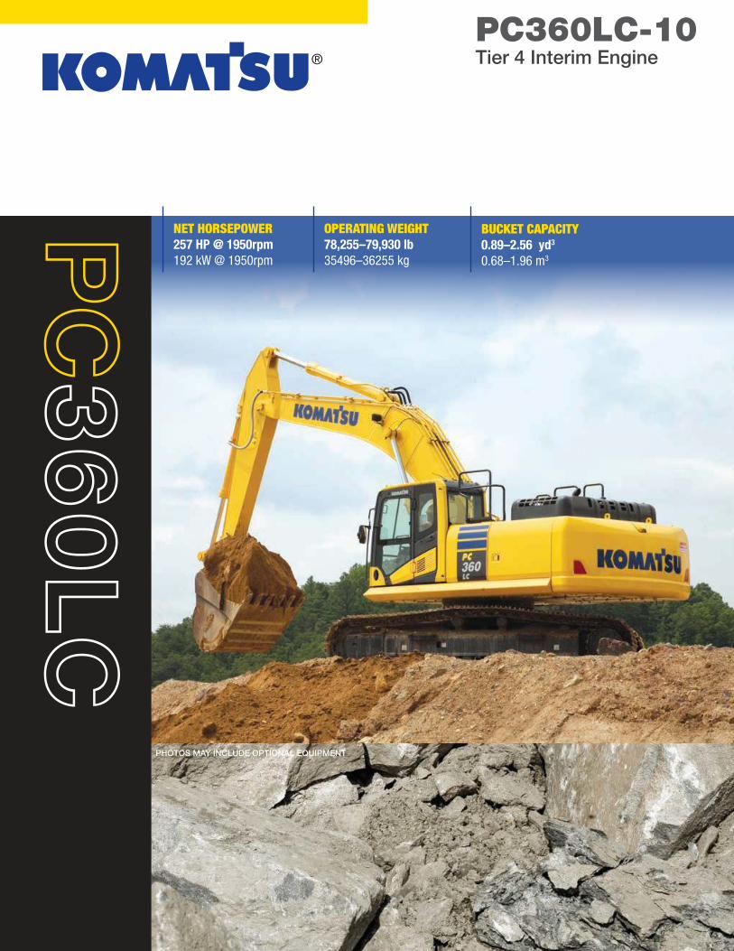
PC360LC-10Tier 4 Interim Engine
OPERATING WEIGHT
78,255–79,930 lb
35496–36255 kg
NET HORSEPOWER
257 HP @ 1950rpm
192 kW @ 1950rpm
BUCKET CAPACITY
0.89–2.56 yd3
0.68–1.96 m3
2
PC
36
0LC
-1
0
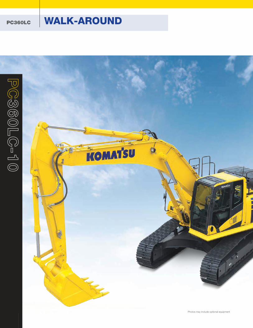
PC360LC WALK-AROUND
Photos may include optional equipment
OPERATING WEIGHT
78,255–79,930 lb
35496–36255 kg
NET HORSEPOWER
257 HP @ 1950rpm
192 kW @ 1950rpm
BUCKET CAPACITY
0.89–2.56 yd3
0.68–1.96 m3
3
PC360LC-10Tier 4 Interim Engine
Komtrax equipped machines can send
location, SMR and operation maps
to a secure website utilizing wireless
technology. Machines also relay error
codes, cautions, maintenance items, fuel
levels, and much more.
®
Large LCD color monitor panel:
■ 7" high resolution screen
■ Provides "Eco-Guidance" for
fuel efficient operation
■ Enhanced
attachment control
Rearview monitoring
system (standard)
Enhanced working modes
are designed to match engine
speed, pump delivery, and system
pressure to the application.
Enhanced working environment
■ High back, heated, and air
suspension operator seat ■ Integrated ROPS cab design
(ISO 12117-2) ■ Cab meets ISO Level 1 Operator
Protective Guard (OPG) top guard
(ISO 10262)
Equipment Management
Monitoring System
(EMMS) continuously monitors
machine operation and vital systems to
identify machine issues and assist with
troubleshooting.
Heavy duty boom design with large
one piece castings provides increased
strength and reliability.
Guardrails (standard) located on
the machine upper structure provide
a convenient work area in front of the
engine.
Battery disconnect switch
allows a technician to disconnect the
power supply before servicing the
machine.
Komatsu designed and
manufactured components
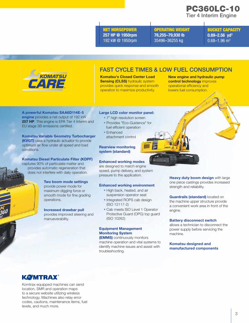
A powerful Komatsu SAA6D114E-5
engine provides a net output of 192 kW
257 HP. This engine is EPA Tier 4 Interim and
EU stage 3B emissions certified.
Komatsu Variable Geometry Turbocharger
(KVGT) uses a hydraulic actuator to provide
optimum air flow under all speed and load
conditions.
Komatsu Diesel Particulate Filter (KDPF)
captures 90% of particulate matter and
provides automatic regeneration that
does not interfere with daily operation.
Two boom mode settings
provide power mode for
maximum digging force or
smooth mode for fine grading
operations.
Increased drawbar pull
provides improved steering and
manueverability.
Komatsu's Closed Center Load
Sensing (CLSS) hydraulic system
provides quick response and smooth
operation to maximize productivity.
New engine and hydraulic pump
control technology improves
operational efficiency and
lowers fuel consumption.
FAST CYCLE TIMES & LOW FUEL CONSUMPTION
PC360LC PERFORMANCE FEATURES
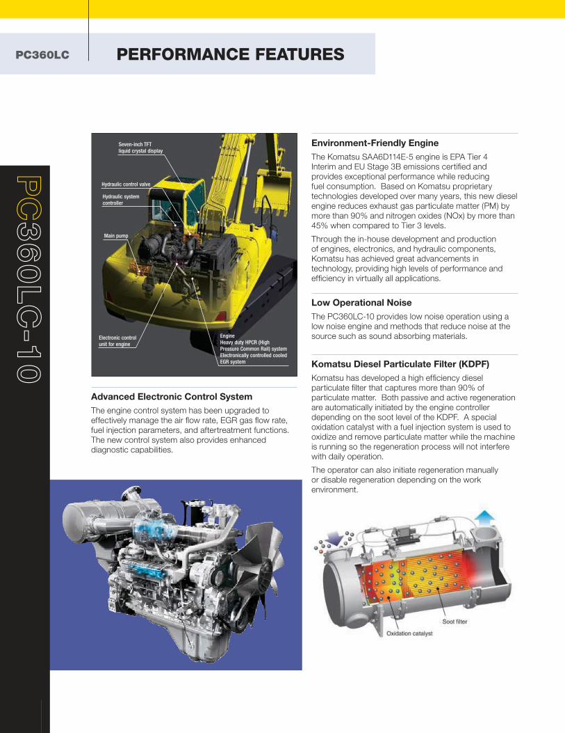
Advanced Electronic Control System
The engine control system has been upgraded to
effectively manage the air flow rate, EGR gas flow rate,
fuel injection parameters, and aftertreatment functions.
The new control system also provides enhanced
diagnostic capabilities.
4
PC
36
0LC
-1
0
Environment-Friendly Engine
The Komatsu SAA6D114E-5 engine is EPA Tier 4
Interim and EU Stage 3B emissions certified and
provides exceptional performance while reducing
fuel consumption. Based on Komatsu proprietary
technologies developed over many years, this new diesel
engine reduces exhaust gas particulate matter (PM) by
more than 90% and nitrogen oxides (NOx) by more than
45% when compared to Tier 3 levels.
Through the in-house development and production
of engines, electronics, and hydraulic components,
Komatsu has achieved great advancements in
technology, providing high levels of performance and
efficiency in virtually all applications.
Low Operational Noise
The PC360LC-10 provides low noise operation using a
low noise engine and methods that reduce noise at the
source such as sound absorbing materials.
Komatsu Diesel Particulate Filter (KDPF)
Komatsu has developed a high efficiency diesel
particulate filter that captures more than 90% of
particulate matter. Both passive and active regeneration
are automatically initiated by the engine controller
depending on the soot level of the KDPF. A special
oxidation catalyst with a fuel injection system is used to
oxidize and remove particulate matter while the machine
is running so the regeneration process will not interfere
with daily operation.
The operator can also initiate regeneration manually
or disable regeneration depending on the work
environment.
Seven-inch TFT
liquid crystal display
Hydraulic control valve
Hydraulic system
controller
Engine
Heavy duty HPCR (High
Pressure Common Rail) system
Electronically controlled cooled
EGR system
Main pump
Electronic control
unit for engine
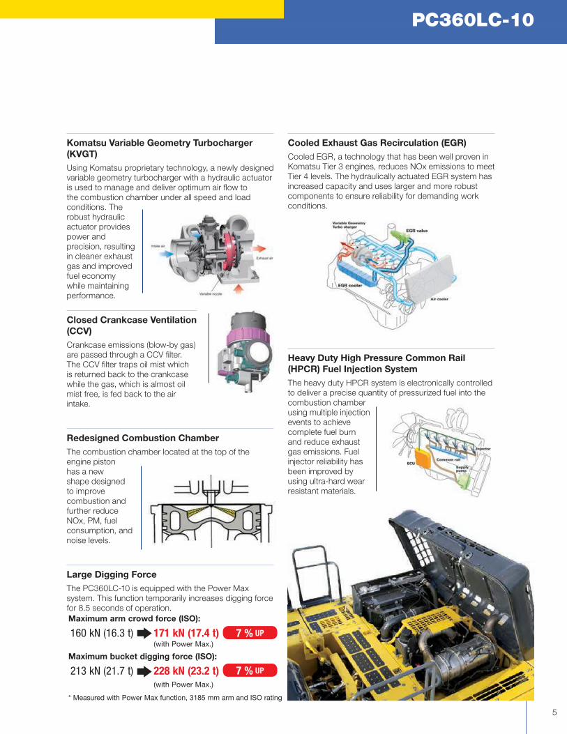
Komatsu Variable Geometry Turbocharger
(KVGT)
Using Komatsu proprietary technology, a newly designed
variable geometry turbocharger with a hydraulic actuator
is used to manage and deliver optimum air flow to
the combustion chamber under all speed and load
conditions. The
robust hydraulic
actuator provides
power and
precision, resulting
in cleaner exhaust
gas and improved
fuel economy
while maintaining
performance.
Closed Crankcase Ventilation
(CCV)
Crankcase emissions (blow-by gas)
are passed through a CCV filter.
The CCV filter traps oil mist which
is returned back to the crankcase
while the gas, which is almost oil
mist free, is fed back to the air
intake.
Redesigned Combustion Chamber
The combustion chamber located at the top of the
engine piston
has a new
shape designed
to improve
combustion and
further reduce
NOx, PM, fuel
consumption, and
noise levels.
Large Digging Force
The PC360LC-10 is equipped with the Power Max
system. This function temporarily increases digging force
for 8.5 seconds of operation.
PC360LC-10
5
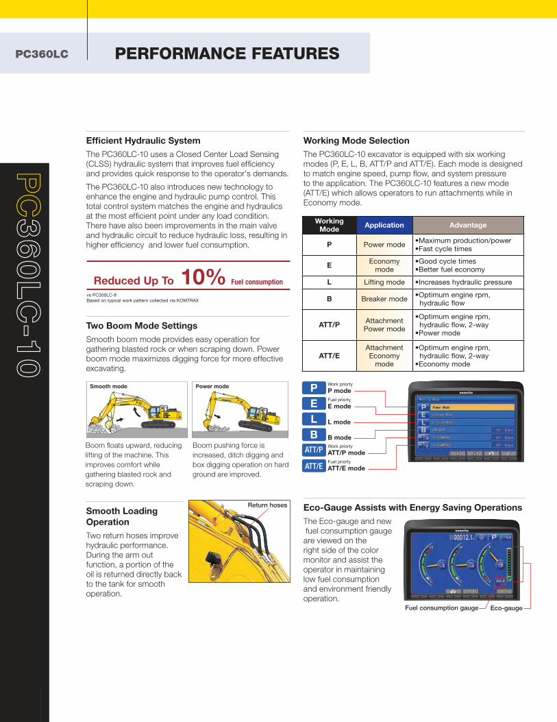
Cooled Exhaust Gas Recirculation (EGR)
Cooled EGR, a technology that has been well proven in
Komatsu Tier 3 engines, reduces NOx emissions to meet
Tier 4 levels. The hydraulically actuated EGR system has
increased capacity and uses larger and more robust
components to ensure reliability for demanding work
conditions.
Heavy Duty High Pressure Common Rail
(HPCR) Fuel Injection System
The heavy duty HPCR system is electronically controlled
to deliver a precise quantity of pressurized fuel into the
combustion chamber
using multiple injection
events to achieve
complete fuel burn
and reduce exhaust
gas emissions. Fuel
injector reliability has
been improved by
using ultra-hard wear
resistant materials.
Maximum arm crowd force (ISO):
160 kN (16.3 t) 171 kN (17.4 t) (with Power Max.)
Maximum bucket digging force (ISO):
213 kN (21.7 t) 228 kN (23.2 t) (with Power Max.)
* Measured with Power Max function, 3185 mm arm and ISO rating
7 % UP
7 % UP
6
PC
36
0LC
-1
0
PC360LC PERFORMANCE FEATURES
Efficient Hydraulic System
The PC360LC-10 uses a Closed Center Load Sensing
(CLSS) hydraulic system that improves fuel efficiency
and provides quick response to the operator's demands.
The PC360LC-10 also introduces new technology to
enhance the engine and hydraulic pump control. This
total control system matches the engine and hydraulics
at the most efficient point under any load condition.
There have also been improvements in the main valve
and hydraulic circuit to reduce hydraulic loss, resulting in
higher efficiency and lower fuel consumption.
Two Boom Mode Settings
Smooth boom mode provides easy operation for
gathering blasted rock or when scraping down. Power
boom mode maximizes digging force for more effective
excavating.
Smooth Loading
Operation
Two return hoses improve
hydraulic performance.
During the arm out
function, a portion of the
oil is returned directly back
to the tank for smooth
operation.
Eco-Gauge Assists with Energy Saving Operations
The Eco-gauge and new
fuel consumption gauge
are viewed on the
right side of the color
monitor and assist the
operator in maintaining
low fuel consumption
and environment friendly
operation.
Smooth mode Power mode
Reduced Up To 10% Fuel consumption
vs PC350LC-8
Based on typical work pattern collected via KOMTRAX
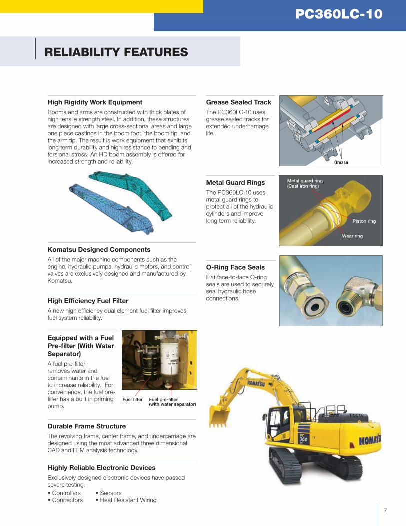
Working Mode
Application Advantage
P Power mode•Maximumproduction/power •Fastcycletimes
EEconomy
mode•Goodcycletimes •Betterfueleconomy
L Lifting mode •Increaseshydraulicpressure
B Breaker mode•Optimumenginerpm, hydraulic flow
ATT/PAttachment Power mode
•Optimumenginerpm, hydraulic flow, 2-way•Powermode
ATT/EAttachment Economy
mode
•Optimumenginerpm, hydraulic flow, 2-way•Economymode
Eco-gauge
P
E
L
B
ATT/P
ATT/E
Work priorty
P mode
Fuelpriorty
E mode
L mode
B mode
Work priorty
ATT/P mode
Fuelpriorty
ATT/E mode
Fuel consumption gauge
Working Mode Selection
The PC360LC-10 excavator is equipped with six working
modes (P, E, L, B, ATT/P and ATT/E). Each mode is designed
to match engine speed, pump flow, and system pressure
to the application. The PC360LC-10 features a new mode
(ATT/E) which allows operators to run attachments while in
Economy mode.
Boom floats upward, reducing
lifting of the machine. This
improves comfort while
gathering blasted rock and
scraping down.
Boom pushing force is
increased, ditch digging and
box digging operation on hard
ground are improved.
Return hoses
Grease Sealed Track
The PC360LC-10 uses
grease sealed tracks for
extended undercarriage
life.
Metal Guard Rings
The PC360LC-10 uses
metal guard rings to
protect all of the hydraulic
cylinders and improve
long term reliability.
O-Ring Face Seals
Flat face-to-face O-ring
seals are used to securely
seal hydraulic hose
connections.
High Rigidity Work Equipment
Booms and arms are constructed with thick plates of
high tensile strength steel. In addition, these structures
are designed with large cross-sectional areas and large
one piece castings in the boom foot, the boom tip, and
the arm tip. The result is work equipment that exhibits
long term durability and high resistance to bending and
torsional stress. An HD boom assembly is offered for
increased strength and reliability.
Komatsu Designed Components
All of the major machine components such as the
engine, hydraulic pumps, hydraulic motors, and control
valves are exclusively designed and manufactured by
Komatsu.
High Efficiency Fuel Filter
A new high efficiency dual element fuel filter improves
fuel system reliability.
Equipped with a Fuel
Pre-filter (With Water
Separator)
A fuel pre-filter
removes water and
contaminants in the fuel
to increase reliability. For
convenience, the fuel pre-
filter has a built in priming
pump.
Durable Frame Structure
The revolving frame, center frame, and undercarriage are
designed using the most advanced three dimensional
CAD and FEM analysis technology.
Highly Reliable Electronic Devices
Exclusively designed electronic devices have passed
severe testing.
•Controllers •Sensors•Connectors •HeatResistantWiring
RELIABILITY FEATURES
PC360LC-10
7
Grease
Metal guard ring(Cast iron ring)
Piston ring
Wear ring
Fuel pre-filter(with water separator)
Fuel filter

8
PC
36
0LC
-1
0
PC360LC WORKING ENVIRONMENT
Newly Designed Wide Spacious Cab
The newly designed wide spacious cab features a high
back, fully adjustable seat with a reclining backrest. The
console and seat have an integrated design so that they
move together and
provide additional
comfort for the
operator.
The new higher
capacity operator seat
has been enhanced to
provide more comfort.
•Heated
•AirSuspension
•IntegratedSeat
•ConsoleMounted Arm Rests
Low Cab Noise
The new cab design is highly rigid and has excellent
sound absorption ability. By improving noise source
reduction and by using a low noise engine, hydraulic
equipment, and air conditioner, this machine is able to
generate low noise levels similar to that of a modern
automobile.
Automatic Air Conditioner
The automatic air conditioner
allows the operator to easily
and precisely set the cab
atmosphere using the large
LCD color monitor panel.
The bi-level control function
improves air flow and
keeps the inside of the cab
comfortable throughout the year.
Pressurized Cab
The air conditioner, air filter, and a higher internal cab
air pressure minimize the amount of external dust that
enters the cab.
Low Vibration with Viscous Cab Mounts
The PC360LC-10 uses viscous mounts for the cab that
incorporate a longer stroke and the addition of a spring.
The cab damper mounting combined with a high rigidity
deck reduces vibration at the operator’s seat.
Auxiliary Input
(MP3 Jack)
By connecting an auxiliary
device such as an MP3
player to the auxiliary input,
the operator can hear the
sound through the speakers
installed in the cab.
Rubber
Silicon
Oil
Spring
Operational "ECO" Guidance
The monitor panel provides operational advice to the
operator to help improve machine efficiency and lower fuel
consumption. The operator can access the ECO guidance
menu to check the Operation Records, Eco Guidance
Records, and Average Fuel Consumption Logs.
Improved Attachment Control
The PC360LC-10 is capable of storing up to ten different
attachments in the new monitor panel. The name of each
attachment can be changed for better tool management.
Hydraulic flow rates can be easily adjusted for one-way and
two-way flow attachments.
PC360LC-10
9
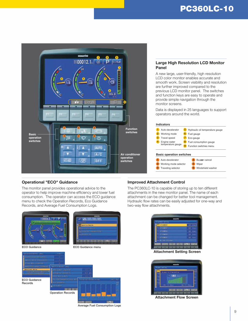
Large High Resolution LCD Monitor
Panel
A new large, user-friendly, high resolution
LCD color monitor enables accurate and
smooth work. Screen visibility and resolution
are further improved compared to the
previous LCD monitor panel. The switches
and function keys are easy to operate and
provide simple navigation through the
monitor screens.
Data is displayed in 25 languages to support
operators around the world.
6
7
8
9
1
2
3
4
5
1
2
3
4
5
6
Hydraulic oil temperature gauge
Fuel gauge
Eco-gauge
Fuel consumption gauge
Function switches menu
Auto-decelerator
Working mode
Travel speed
Engine water temperature gauge
Auto-decelerator
Working mode selector
Traveling selector
Buzzer cancel
Wiper
Windshield washer
Indicators
Basic operation switches
Basic
operation
switches
Air conditioner
operation
switches
Function
switches
9
8
1 2 3
4 5 6
7
5 6
1 2 3
4
Average Fuel Consumption Logs
ECO Guidance Records
Operation Records
ECO Guidance menuECO Guidance
Attachment Setting Screen
Attachment Flow Screen
10
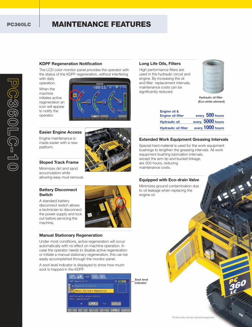
KDPF Regeneration Notification
The LCD color monitor panel provides the operator with
the status of the KDPF regeneration, without interfering
with daily
operation.
When the
machine
initiates active
regeneration an
icon will appear
to notify the
operator.
Easier Engine Access
Engine maintenance is
made easier with a new
platform.
Sloped Track Frame
Minimizes dirt and sand
accumulation while
allowing easy mud removal.
Battery Disconnect
Switch
A standard battery
disconnect switch allows
a technician to disconnect
the power supply and lock
out before servicing the
machine.
Manual Stationary Regeneration
Under most conditions, active regeneration will occur
automatically with no effect on machine operation. In
case the operator needs to disable active regeneration
or initiate a manual stationary regeneration, this can be
easily accomplished through the monitor panel.
A soot level indicator is displayed to show how much
soot is trapped in the KDPF.
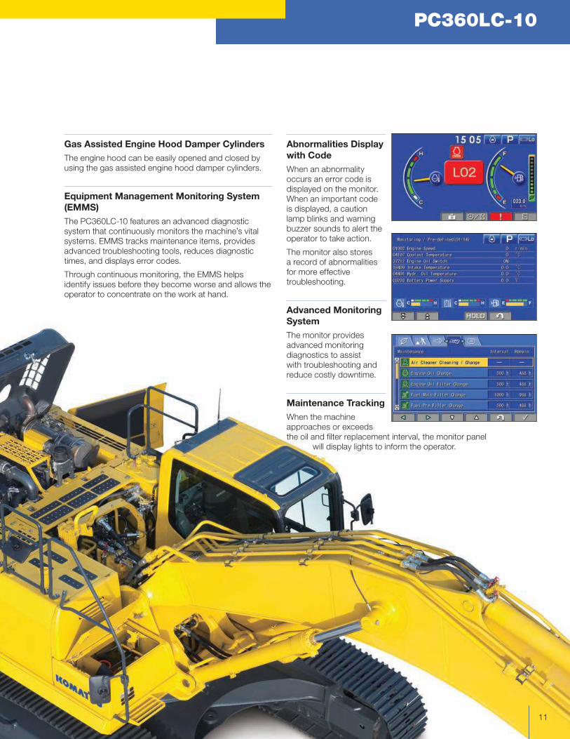
Long Life Oils, Filters
High performance filters are
used in the hydraulic circuit and
engine. By increasing the oil
and filter replacement intervals,
maintenance costs can be
significantly reduced.
Extended Work Equipment Greasing Intervals
Special hard material is used for the work equipment
bushings to lengthen the greasing intervals. All work
equipment bushing lubrication intervals,
except the arm tip and bucket linkage,
are 500 hours, reducing
maintenance costs.
PC
36
0LC
-1
0
Photos may include optional equipment
PC360LC MAINTENANCE FEATURES
Hydraulic oil filter
(Eco-white element)
Engine oil &
Engine oil filter every 500 hours
Hydraulic oil every 5000 hours
Hydraulic oil filter every 1000 hours
Soot level indicator
Equipped with Eco-drain Valve
Minimizes ground contamination due
to oil leakage when replacing the
engine oil.
PC360LC-10
11
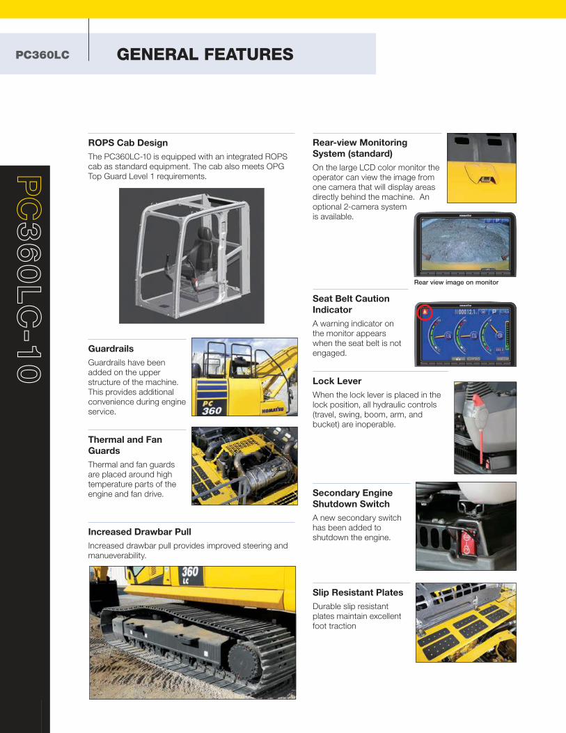
Abnormalities Display
with Code
When an abnormality
occurs an error code is
displayed on the monitor.
When an important code
is displayed, a caution
lamp blinks and warning
buzzer sounds to alert the
operator to take action.
The monitor also stores
a record of abnormalities
for more effective
troubleshooting.
Advanced Monitoring
System
The monitor provides
advanced monitoring
diagnostics to assist
with troubleshooting and
reduce costly downtime.
Maintenance Tracking
When the machine
approaches or exceeds
the oil and filter replacement interval, the monitor panel
will display lights to inform the operator.
Gas Assisted Engine Hood Damper Cylinders
The engine hood can be easily opened and closed by
using the gas assisted engine hood damper cylinders.
Equipment Management Monitoring System
(EMMS)
The PC360LC-10 features an advanced diagnostic
system that continuously monitors the machine’s vital
systems. EMMS tracks maintenance items, provides
advanced troubleshooting tools, reduces diagnostic
times, and displays error codes.
Through continuous monitoring, the EMMS helps
identify issues before they become worse and allows the
operator to concentrate on the work at hand.
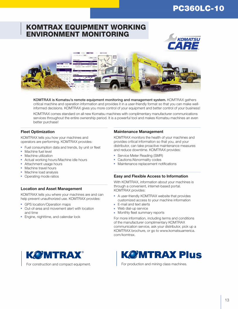
Rear-view Monitoring
System (standard)
On the large LCD color monitor the
operator can view the image from
one camera that will display areas
directly behind the machine. An
optional 2-camera system
is available.
Seat Belt Caution
Indicator
A warning indicator on
the monitor appears
when the seat belt is not
engaged.
Lock Lever
When the lock lever is placed in the
lock position, all hydraulic controls
(travel, swing, boom, arm, and
bucket) are inoperable.
Secondary Engine
Shutdown Switch
A new secondary switch
has been added to
shutdown the engine.
Slip Resistant Plates
Durable slip resistant
plates maintain excellent
foot traction
PC
36
0LC
-1
0
12
ROPS Cab Design
The PC360LC-10 is equipped with an integrated ROPS
cab as standard equipment. The cab also meets OPG
Top Guard Level 1 requirements.
Guardrails
Guardrails have been
added on the upper
structure of the machine.
This provides additional
convenience during engine
service.
Thermal and Fan
Guards
Thermal and fan guards
are placed around high
temperature parts of the
engine and fan drive.
Increased Drawbar Pull
Increased drawbar pull provides improved steering and
manueverability.
PC360LC GENERAL FEATURES
Rear view image on monitor
PC360LC-10PC360LC-10
13
KOMTRAX EQUIPMENT WORKING ENVIRONMENT MONITORING
KOMTRAX is Komatsu’s remote equipment monitoring and management system. KOMTRAX gathers
critical machine and operation information and provides it in a user-friendly format so that you can make well-
informed decisions. KOMTRAX gives you more control of your equipment and better control of your business!
KOMTRAX comes standard on all new Komatsu machines with complimentary manufacturer communications
services throughout the entire ownership period. It is a powerful tool and makes Komatsu machines an even
better purchase!
Fleet Optimization
KOMTRAX tells you how your machines and
operators are performing. KOMTRAX provides:
■ Fuel consumption data and trends, by unit or fleet ■ Machine fuel level ■ Machine utilization ■ Actual working hours/Machine idle hours ■ Attachment usage hours ■ Machine travel hours ■ Machine load analysis ■ Operating mode ratios
Location and Asset Management
KOMTRAX tells you where your machines are and can
help prevent unauthorized use. KOMTRAX provides:
■ GPS location/Operation maps ■ Out-of-area and movement alert with location
and time ■ Engine, nighttime, and calendar lock
Maintenance Management
KOMTRAX monitors the health of your machines and
provides critical information so that you, and your
distributor, can take proactive maintenance measures
and reduce downtime. KOMTRAX provides:
■ Service Meter Reading (SMR) ■ Cautions/Abnormality codes ■ Maintenance replacement notifications
Easy and Flexible Access to Information
With KOMTRAX, information about your machines is
through a convenient, internet-based portal.
KOMTRAX provides:
■ A user-friendly KOMTRAX website that provides
customized access to your machine information ■ E-mail and text alerts ■ Web dial-up service ■ Monthly fleet summary reports
For more information, including terms and conditions
of the manufacturer complimentary KOMTRAX
communication service, ask your distributor, pick up a
KOMTRAX brochure, or go to www.komatsuamerica.
com/komtrax.
For construction and compact equipment. For production and mining class machines.
®
PC
36
0LC
-1
0
14
KOMATSU PARTS & SERVICE SUPPORT
PC360LC
Komatsu Parts Support
Because downtime can be costly, Komatsu maintains a
a strategic distribution network throughout the U.S. and
Canada, to ensure superior parts availability and to keep
your Komatsu machine up and running.
■ Komatsu America has nine Parts Distribution Centers
strategically located throughout the U.S. and Canada
■ Komatsu America’s Parts distribution network is
accessible 24/7/365 to fulfill your parts needs
■ Komatsu has a distributor network of over 325 locations
across the U.S. and Canada
■ Online parts ordering available through Komatsu eParts,
24/7/365. (See distributor for details)
■ Komatsu offers a a full line of factory Remanufactured
products with same-as-new warranties at a significant
cost reduction:
1. Complete Engine Assemblies
2. Transmissions
3. Torque Converters
4. Hydraulic components
5. Starters, Alternators, turbochargers
and circuit boards
Komatsu Oil and Wear Analysis (KOWA)
The KOWA program uses independent laboratories across
the United States to determine how your machine is
performing based on a small sample of oil or other fluid. Just
like a doctor will take a blood test to check on your personal
health, KOWA allows you to check how your equipment is
performing. Used with PM Clinic and PM Tune Up, KOWA
is one of your best tools for proactively maintaining your
Komatsu equipment and maximizing it’s availability and
performance.
KOWA detects fuel dilution and coolant leaks, identifies
contaminants, and measures wear-metals. Your distributor
will help you interpret this information so you can identify
potential problems and head them off before they lead to
major repairs.
For more information of all of the manufacturer sponsored programs mentioned in this brochure, including terms and conditions of the individual programs, please speak with your distributor or go to www.komatsuamerica.com
Komatsu CARE – Complimentary Scheduled
Maintenance
Komatsu remains focused on lowering the customer’s
ownership costs by engineering machines with increased
fuel efficiency and productivity. In addition, one Komatsu
CARE program aimed at further reducing your owning
and operating costs is Complimentary Scheduled
Maintenance. Komatsu machine owners can now rely
on their Komatsu Distributor to perform the preventative
maintenance on their Komatsu Tier 4 machines.
■ Complimentary scheduled maintenance for the earlier
of 3 years or 2,000 hours is standard on all Komatsu
Tier 4 construction machines and is available at all
distributors in the U.S. and Canada.
■ Service is performed by factory certified technicians
using only Komatsu Genuine parts and fluids
■ Significantly lowers your cost of ownership while
maintaining high equipment uptime and reliability
■ Increases resale value and provides detailed
maintenance records
Komatsu CARE – Extended Coverage
Komatsu equipment is built to withstand harsh operating
environments, but our Extended Coverage can provide
further peace of mind by protecting customers from
unplanned expenses and impacts in cash flow.
Purchasing Komatsu CARE’s Extended Coverage locks-
in the cost of covered parts and labor for the extended
warranty period and helps to turn these variable expenses
into a fixed cost. ■ No Stop Loss or Loss Limits imposed, regardless of
the coverage type or repair expense
■ Any combination of months and hours out to five years
and 10,000 engine hours – KOWA kits included
■ Coverage premium can be rolled into the machine
financing at time of sale or purchased any time before
the expiration of the machine's standard warranty
■ Coverage is fully transferable and honored by all
Komatsu distributors throughout the U.S. and Canada
Komatsu CARE – Total CARE
Total CARE combines the benefits of the Komatsu
CARE Scheduled Maintenance and Extended Coverage
programs on your Tier 4 machine. This ensures the
use of Komatsu genuine parts and fluids during regular
maintenance intervals as well as highly skilled and efficient
technicians to perform any other warranty repair work that
might be necessary to keep your Komatsu equipment
running like new.
Komatsu is an industry leader in building reliable and
technologically advanced machines. It is only fitting that
we would provide superior Product Support. Komatsu and
its distributors are focused on providing their customers
unparalleled Product Support throughout the entire
lifecycle of the machine. It’s called Komatsu CARE.
PC360LC-10
15
SPECIFICATIONS
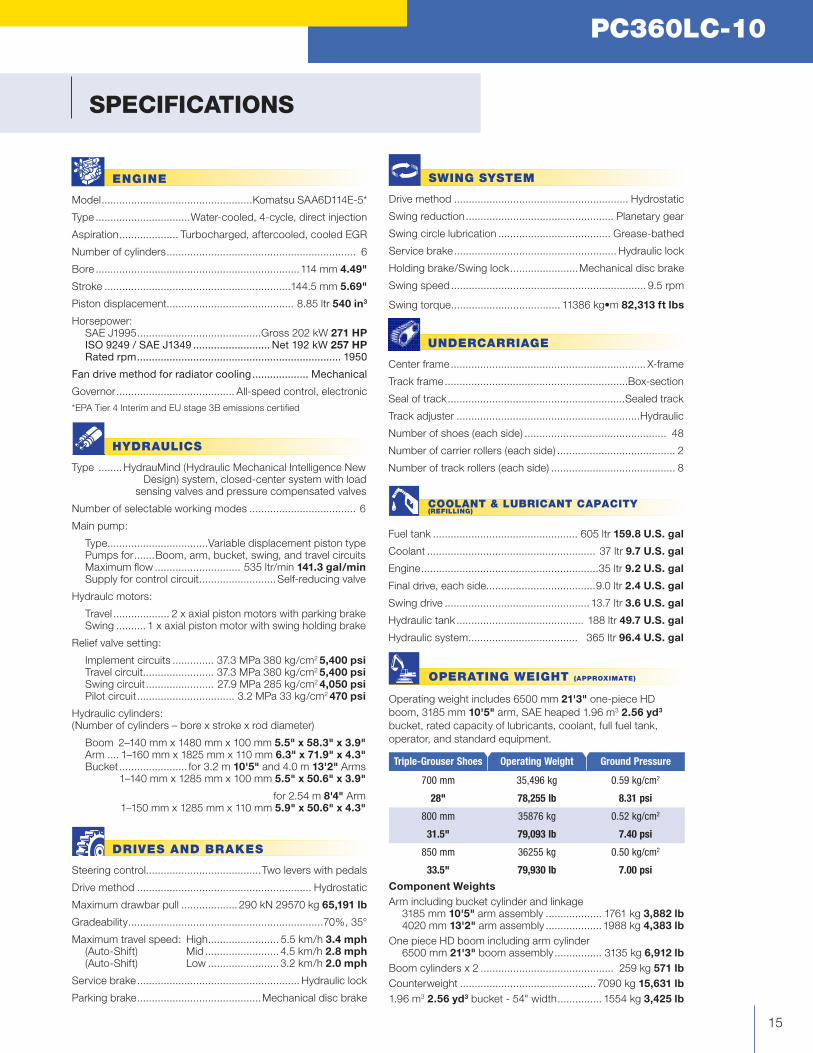
UNDERCARRIAGE
Center frame .................................................................. X-frame
Track frame ..............................................................Box-section
Seal of track ............................................................Sealed track
Track adjuster ..............................................................Hydraulic
Number of shoes (each side) ................................................ 48
Number of carrier rollers (each side) ........................................ 2
Number of track rollers (each side) .......................................... 8
ENGINE
Model ...................................................Komatsu SAA6D114E-5*
Type ................................Water-cooled, 4-cycle, direct injection
Aspiration .................... Turbocharged, aftercooled, cooled EGR
Number of cylinders ................................................................ 6
Bore .....................................................................114 mm 4.49"
Stroke ...............................................................144.5 mm 5.69"
Piston displacement........................................... 8.85 ltr 540 in3
Horsepower: SAE J1995 ..........................................Gross 202 kW 271 HP ISO 9249 / SAE J1349 .......................... Net 192 kW 257 HP Rated rpm ..................................................................... 1950
Fandrivemethodforradiatorcooling ................... Mechanical
Governor ........................................ All-speed control, electronic
*EPA Tier 4 Interim and EU stage 3B emissions certified
SWING SYSTEM
Drive method ........................................................... Hydrostatic
Swing reduction .................................................. Planetary gear
Swing circle lubrication ...................................... Grease-bathed
Service brake ....................................................... Hydraulic lock
Holding brake/Swing lock .......................Mechanical disc brake
Swing speed .................................................................. 9.5 rpm
Swing torque ..................................... 11386kg•m82,313 ft lbs
HYDRAULICS
Type ........HydrauMind (Hydraulic Mechanical Intelligence New Design) system, closed-center system with load
sensing valves and pressure compensated valves
Number of selectable working modes .................................... 6
Main pump:
Type ..................................Variable displacement piston type Pumps for .......Boom, arm, bucket, swing, and travel circuits Maximum flow ............................. 535 ltr/min 141.3 gal/min Supply for control circuit ..........................Self-reducing valve
Hydraulc motors:
Travel ................... 2 x axial piston motors with parking brake Swing .......... 1 x axial piston motor with swing holding brake
Relief valve setting:
Implement circuits .............. 37.3 MPa 380 kg/cm2 5,400 psi Travel circuit........................ 37.3 MPa 380 kg/cm2 5,400 psi Swing circuit ....................... 27.9 MPa 285 kg/cm2 4,050 psi Pilot circuit ................................. 3.2 MPa 33 kg/cm2 470 psi
Hydraulic cylinders:(Number of cylinders – bore x stroke x rod diameter)
Boom 2–140 mm x 1480 mm x 100 mm 5.5" x 58.3" x 3.9" Arm .... 1–160 mm x 1825 mm x 110 mm 6.3" x 71.9" x 4.3" Bucket ....................... for 3.2 m 10'5" and 4.0 m 13'2" Arms 1–140 mm x 1285 mm x 100 mm 5.5" x 50.6" x 3.9"
for 2.54 m 8'4" Arm 1–150 mm x 1285 mm x 110 mm 5.9" x 50.6" x 4.3"
DRIVES AND BRAKES
Steering control.......................................Two levers with pedals
Drive method ........................................................... Hydrostatic
Maximum drawbar pull ................... 290 kN 29570 kg 65,191 lb
Gradeability ..................................................................70%, 35°
Maximum travel speed: High ........................ 5.5 km/h 3.4 mph (Auto-Shift) Mid ......................... 4.5 km/h 2.8 mph (Auto-Shift) Low ........................ 3.2 km/h 2.0 mph
Service brake ....................................................... Hydraulic lock
Parking brake ..........................................Mechanical disc brake
COOLANT & LUBRICANT CAPACITY(REFILLING)
Fuel tank ................................................. 605 ltr 159.8 U.S. gal
Coolant ......................................................... 37 ltr 9.7 U.S. gal
Engine ............................................................35 ltr 9.2 U.S. gal
Final drive, each side.....................................9.0 ltr 2.4 U.S. gal
Swing drive ................................................. 13.7 ltr 3.6 U.S. gal
Hydraulic tank ........................................... 188 ltr 49.7 U.S. gal
Hydraulic system ..................................... 365 ltr 96.4 U.S. gal
OPERATING WEIGHT (APPROXIMATE)
Operating weight includes 6500 mm 21'3" one-piece HD
boom, 3185 mm 10'5" arm, SAE heaped 1.96 m3 2.56 yd3
bucket, rated capacity of lubricants, coolant, full fuel tank,
operator, and standard equipment.
Triple-Grouser Shoes Operating Weight Ground Pressure
700 mm 35,496 kg 0.59 kg/cm2
28" 78,255 lb 8.31 psi
800 mm 35876 kg 0.52 kg/cm2
31.5" 79,093 lb 7.40 psi
850 mm 36255 kg 0.50 kg/cm2
33.5" 79,930 lb 7.00 psi
Component Weights
Arm including bucket cylinder and linkage 3185 mm 10'5" arm assembly ................... 1761 kg 3,882 lb 4020 mm 13'2" arm assembly ................... 1988 kg 4,383 lb
One piece HD boom including arm cylinder 6500 mm 21'3" boom assembly ................ 3135 kg 6,912 lb
Boom cylinders x 2 ............................................. 259 kg 571 lb
Counterweight .............................................. 7090 kg 15,631 lb
1.96 m3 2.56 yd3 bucket - 54" width ............... 1554 kg 3,425 lb
PC
36
0LC
-1
0
PRODUCTIVITY & ECOLOGY FEATURES
16
SPECIFICATIONS
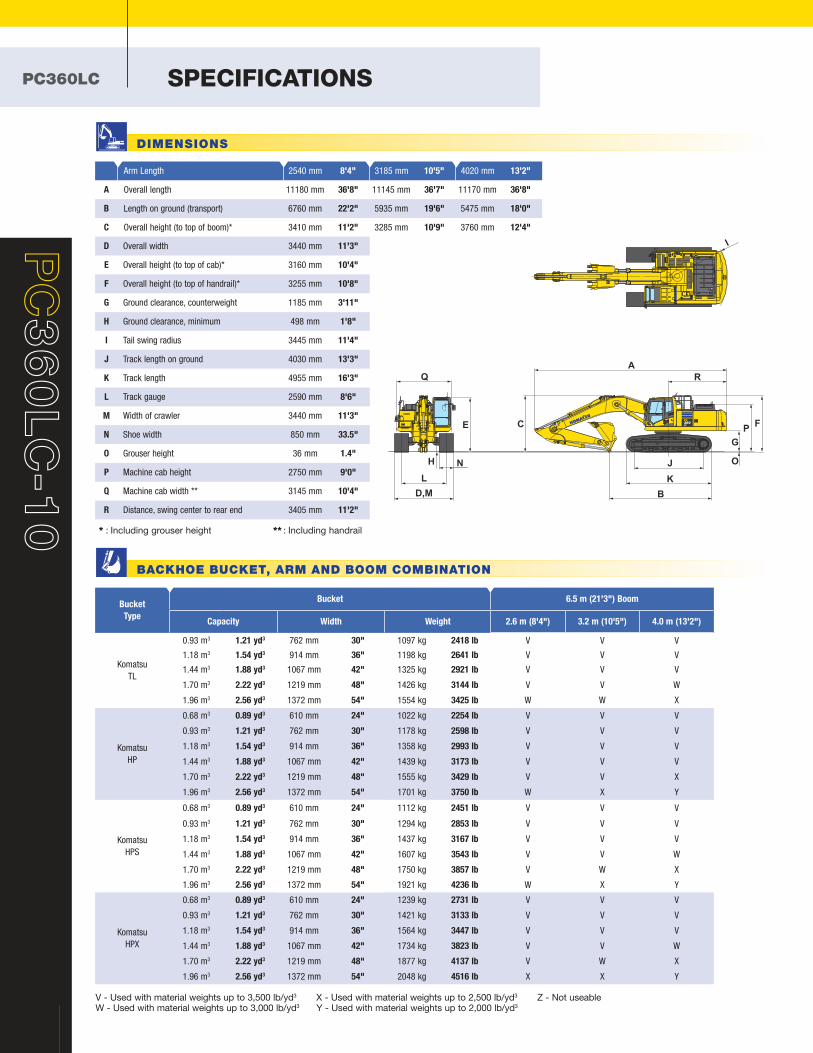
V - Used with material weights up to 3,500 lb/yd3
W - Used with material weights up to 3,000 lb/yd3
X - Used with material weights up to 2,500 lb/yd3
Y - Used with material weights up to 2,000 lb/yd3
Z - Not useable
* : Including grouser height ** : Including handrail
Arm Length 2540 mm 8'4" 3185 mm 10'5" 4020 mm 13'2"
A Overall length 11180 mm 36'8" 11145 mm 36'7" 11170 mm 36'8"
B Length on ground (transport) 6760 mm 22'2" 5935 mm 19'6" 5475 mm 18'0"
C Overall height (to top of boom)* 3410 mm 11'2" 3285 mm 10'9" 3760 mm 12'4"
D Overall width 3440 mm 11'3"
E Overall height (to top of cab)* 3160 mm 10'4"
F Overall height (to top of handrail)* 3255 mm 10'8"
G Ground clearance, counterweight 1185 mm 3'11"
H Ground clearance, minimum 498 mm 1'8"
I Tail swing radius 3445 mm 11'4"
J Track length on ground 4030 mm 13'3"
K Track length 4955 mm 16'3"
L Track gauge 2590 mm 8'6"
M Width of crawler 3440 mm 11'3"
N Shoe width 850 mm 33.5"
O Grouser height 36 mm 1.4"
P Machine cab height 2750 mm 9'0"
Q Machine cab width ** 3145 mm 10'4"
R Distance, swing center to rear end 3405 mm 11'2"
I
NH
CE
R
A
D,M
L
J O
G
PF
K
B
Q
Bucket
Type
Bucket 6.5 m (21'3") Boom
Capacity Width Weight 2.6 m (8'4") 3.2 m (10'5") 4.0 m (13'2")
Komatsu
TL
0.93 m3 1.21 yd3 762 mm 30" 1097 kg 2418 lb V V V
1.18 m3 1.54 yd3 914 mm 36" 1198 kg 2641 lb V V V
1.44 m3 1.88 yd3 1067 mm 42" 1325 kg 2921 lb V V V
1.70 m3 2.22 yd3 1219 mm 48" 1426 kg 3144 lb V V W
1.96 m3 2.56 yd3 1372 mm 54" 1554 kg 3425 lb W W X
Komatsu
HP
0.68 m3 0.89 yd3 610 mm 24" 1022 kg 2254 lb V V V
0.93 m3 1.21 yd3 762 mm 30" 1178 kg 2598 lb V V V
1.18 m3 1.54 yd3 914 mm 36" 1358 kg 2993 lb V V V
1.44 m3 1.88 yd3 1067 mm 42" 1439 kg 3173 lb V V V
1.70 m3 2.22 yd3 1219 mm 48" 1555 kg 3429 lb V V X
1.96 m3 2.56 yd3 1372 mm 54" 1701 kg 3750 lb W X Y
Komatsu
HPS
0.68 m3 0.89 yd3 610 mm 24" 1112 kg 2451 lb V V V
0.93 m3 1.21 yd3 762 mm 30" 1294 kg 2853 lb V V V
1.18 m3 1.54 yd3 914 mm 36" 1437 kg 3167 lb V V V
1.44 m3 1.88 yd3 1067 mm 42" 1607 kg 3543 lb V V W
1.70 m3 2.22 yd3 1219 mm 48" 1750 kg 3857 lb V W X
1.96 m3 2.56 yd3 1372 mm 54" 1921 kg 4236 lb W X Y
Komatsu
HPX
0.68 m3 0.89 yd3 610 mm 24" 1239 kg 2731 lb V V V
0.93 m3 1.21 yd3 762 mm 30" 1421 kg 3133 lb V V V
1.18 m3 1.54 yd3 914 mm 36" 1564 kg 3447 lb V V V
1.44 m3 1.88 yd3 1067 mm 42" 1734 kg 3823 lb V V W
1.70 m3 2.22 yd3 1219 mm 48" 1877 kg 4137 lb V W X
1.96 m3 2.56 yd3 1372 mm 54" 2048 kg 4516 lb X X Y
PC360LC
DIMENSIONS
BACKHOE BUCKET, ARM AND BOOM COMBINATION
PC360LC-10
17
345678910
5
6
7
8
9
10
11(m)
1112(m)
2
G.L.
2 1 0
-7
-6
-5
-4
-3
-2
-1
0
1
3
4
-8
H
A
C
B
ED
G
F
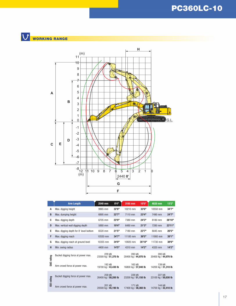
WORKING RANGE
Arm Length 2540 mm 8'4" 3185 mm 10'5" 4020 mm 13'2"
A Max. digging height 9965 mm 32'8" 10210 mm 33'6" 10550 mm 34'7"
B Max. dumping height 6895 mm 22'7" 7110 mm 23'4" 7490 mm 24'7"
C Max. digging depth 6705 mm 22'0" 7380 mm 24'3" 8180 mm 26'10"
D Max. vertical wall digging depth 5880 mm 19'4" 6480 mm 21'3" 7280 mm 23'11"
E Max. digging depth for 8' level bottom 6520 mm 21'5" 7180 mm 23'7" 8045 mm 26'5"
F Max. digging reach 10550 mm 34'7" 11100 mm 36'5" 11900 mm 39'1"
G Max. digging reach at ground level 10355 mm 34'0" 10920 mm 35'10" 11730 mm 38'6"
H Min. swing radius 4400 mm 14'5" 4310 mm 14'2" 4320 mm 14'2"
SA
E r
ati
ng Bucket digging force at power max.
229 kN 200 kN 200 kN23300 kg / 51,370 lb 20400 kg / 44,970 lb 20400 kg / 44,970 lb
Arm crowd force at power max.193 kN 165 kN 139 kN
19700 kg / 43,430 lb 16800 kg / 37,040 lb 14200 kg / 31,310 lb
ISO
ra
tin
g Bucket digging force at power max.259 kN 228 kN 227 kN
26400 kg / 58,200 lb 23200 kg / 51,150 lb 23100 kg / 50,930 lb
Arm crowd force at power max.201 kN 171 kN 144 kN
20500 kg / 45,190 lb 17400 kg / 38,360 lb 14700 kg / 32,410 lb
LIFT CAPACITIES
18
PC
36
0LC
-1
0
PC360LC
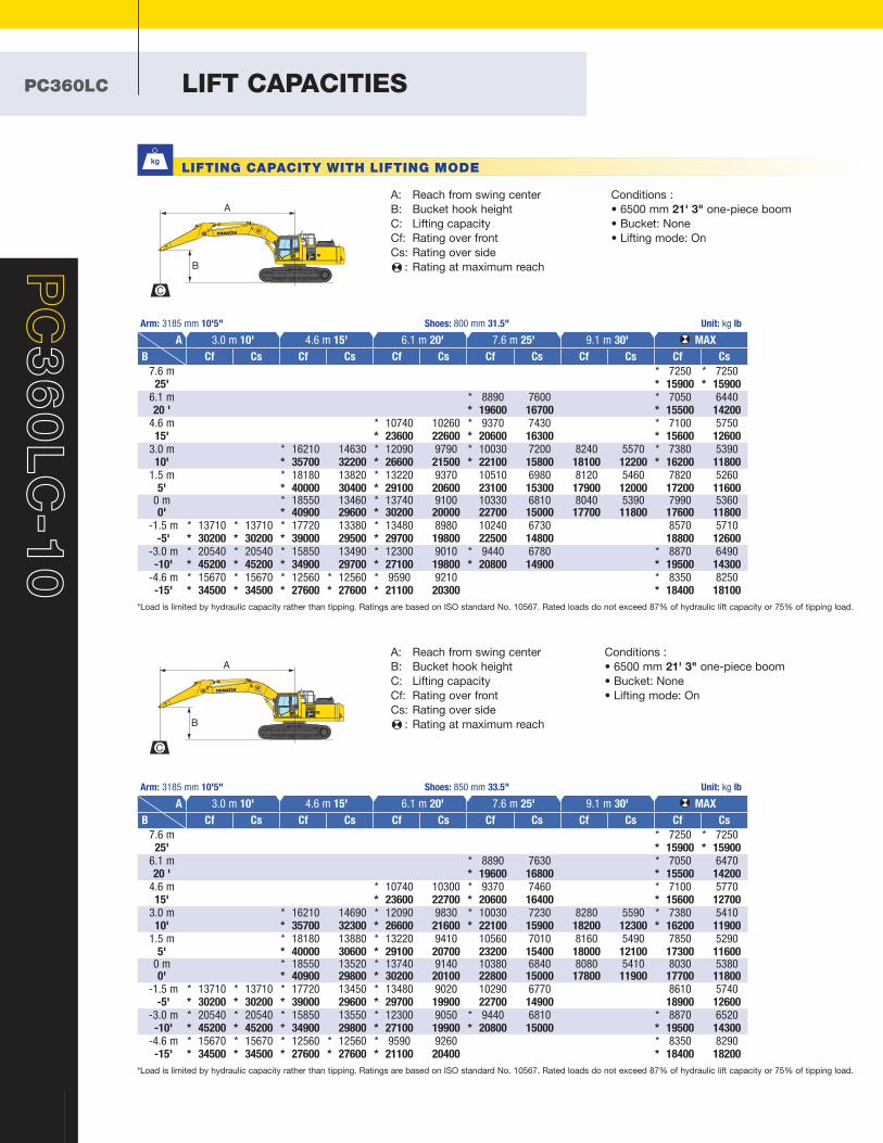
A: Reach from swing center
B: Bucket hook height
C: Lifting capacity
Cf: Rating over front
Cs: Rating over side
: Rating at maximum reach
Conditions :
•6500mm21' 3" one-piece boom
•Bucket:None•Liftingmode:On
*Loadislimitedbyhydrauliccapacityratherthantipping.RatingsarebasedonISOstandardNo.10567.Ratedloadsdonotexceed87%ofhydraulicliftcapacityor75%oftippingload.
Arm: 3185 mm 10'5" Shoes: 800 mm 31.5" Unit: kg lb
A 3.0 m 10' 4.6 m 15' 6.1 m 20' 7.6 m 25' 9.1 m 30' MAX
B Cf Cs Cf Cs Cf Cs Cf Cs Cf Cs Cf Cs
7.6 m * 7250 * 725025' * 15900 * 15900
6.1 m * 8890 7600 * 7050 644020 ' * 19600 16700 * 15500 14200
4.6 m * 10740 10260 * 9370 7430 * 7100 575015' * 23600 22600 * 20600 16300 * 15600 12600
3.0 m * 16210 14630 * 12090 9790 * 10030 7200 8240 5570 * 7380 539010' * 35700 32200 * 26600 21500 * 22100 15800 18100 12200 * 16200 11800
1.5 m * 18180 13820 * 13220 9370 10510 6980 8120 5460 7820 52605' * 40000 30400 * 29100 20600 23100 15300 17900 12000 17200 11600
0 m * 18550 13460 * 13740 9100 10330 6810 8040 5390 7990 53600' * 40900 29600 * 30200 20000 22700 15000 17700 11800 17600 11800
-1.5 m * 13710 * 13710 * 17720 13380 * 13480 8980 10240 6730 8570 5710 -5' * 30200 * 30200 * 39000 29500 * 29700 19800 22500 14800 18800 12600
-3.0 m * 20540 * 20540 * 15850 13490 * 12300 9010 * 9440 6780 * 8870 6490 -10' * 45200 * 45200 * 34900 29700 * 27100 19800 * 20800 14900 * 19500 14300
-4.6 m * 15670 * 15670 * 12560 * 12560 * 9590 9210 * 8350 8250 -15' * 34500 * 34500 * 27600 * 27600 * 21100 20300 * 18400 18100
A: Reach from swing center
B: Bucket hook height
C: Lifting capacity
Cf: Rating over front
Cs: Rating over side
: Rating at maximum reach
Conditions :
•6500mm21' 3" one-piece boom
•Bucket:None•Liftingmode:On
A
B
C
A
B
C
LIFTING CAPACITY WITH LIFTING MODE
*Loadislimitedbyhydrauliccapacityratherthantipping.RatingsarebasedonISOstandardNo.10567.Ratedloadsdonotexceed87%ofhydraulicliftcapacityor75%oftippingload.
Arm: 3185 mm 10'5" Shoes: 850 mm 33.5" Unit: kg lb
A 3.0 m 10' 4.6 m 15' 6.1 m 20' 7.6 m 25' 9.1 m 30' MAX
B Cf Cs Cf Cs Cf Cs Cf Cs Cf Cs Cf Cs
7.6 m * 7250 * 725025' * 15900 * 15900
6.1 m * 8890 7630 * 7050 647020 ' * 19600 16800 * 15500 14200
4.6 m * 10740 10300 * 9370 7460 * 7100 577015' * 23600 22700 * 20600 16400 * 15600 12700
3.0 m * 16210 14690 * 12090 9830 * 10030 7230 8280 5590 * 7380 541010' * 35700 32300 * 26600 21600 * 22100 15900 18200 12300 * 16200 11900
1.5 m * 18180 13880 * 13220 9410 10560 7010 8160 5490 7850 52905' * 40000 30600 * 29100 20700 23200 15400 18000 12100 17300 11600
0 m * 18550 13520 * 13740 9140 10380 6840 8080 5410 8030 53800' * 40900 29800 * 30200 20100 22800 15000 17800 11900 17700 11800
-1.5 m * 13710 * 13710 * 17720 13450 * 13480 9020 10290 6770 8610 5740 -5' * 30200 * 30200 * 39000 29600 * 29700 19900 22700 14900 18900 12600
-3.0 m * 20540 * 20540 * 15850 13550 * 12300 9050 * 9440 6810 * 8870 6520 -10' * 45200 * 45200 * 34900 29800 * 27100 19900 * 20800 15000 * 19500 14300
-4.6 m * 15670 * 15670 * 12560 * 12560 * 9590 9260 * 8350 8290 -15' * 34500 * 34500 * 27600 * 27600 * 21100 20400 * 18400 18200
PC360LC-10
19
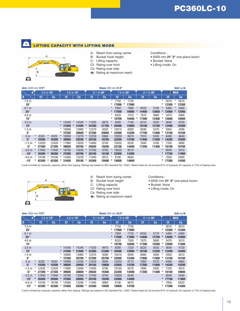
A: Reach from swing center
B: Bucket hook height
C: Lifting capacity
Cf: Rating over front
Cs: Rating over side
: Rating at maximum reach
Conditions :
•6500mm21' 3" one-piece boom
•Bucket:None•Liftingmode:On
A: Reach from swing center
B: Bucket hook height
C: Lifting capacity
Cf: Rating over front
Cs: Rating over side
: Rating at maximum reach
Conditions :
•6500mm21' 3" one-piece boom
•Bucket:None•Liftingmode:On
A
B
C
A
B
C
LIFTING CAPACITY WITH LIFTING MODE
*Loadislimitedbyhydrauliccapacityratherthantipping.RatingsarebasedonISOstandardNo.10567.Ratedloadsdonotexceed87%ofhydraulicliftcapacityor75%oftippingload.
Arm: 4020 mm 13'2" Shoes: 800 mm 31.5" Unit: kg lb
A 3.0 m 10' 4.6 m 15' 6.1 m 20' 7.6 m 25' 9.1 m 30' MAX
B Cf Cs Cf Cs Cf Cs Cf Cs Cf Cs Cf Cs
7.6 m * 7750 * 7750 * 5610 * 561025' * 17000 * 17000 * 12300 * 12300
6.1 m * 7950 7680 * 6550 5740 * 5460 * 546020 ' * 17500 16900 * 14400 12600 * 12000 * 12000
4.6 m * 8520 7470 * 7870 5660 * 5470 498015' * 18700 16400 * 17300 12400 * 12000 10900
3.0 m * 14340 * 14340 * 11020 9870 * 9280 7190 8210 5520 * 5640 470010' * 31600 * 31600 * 24300 21700 * 20400 15800 18100 12100 * 12400 10300
1.5 m * 16890 13900 * 12370 9350 * 10010 6900 8040 5370 * 5950 45905' * 37200 30600 * 27200 20600 * 22000 15200 17700 11800 * 13100 10100
0 m * 8320 * 8320 * 18090 13270 * 13230 8960 10200 6670 7910 5240 * 6480 46400' * 18300 * 18300 * 39800 29200 * 29100 19700 22500 14700 17400 11500 * 14200 10200
-1.5 m * 12420 12420 * 17980 13030 * 13400 8740 10050 6530 7840 5180 * 7330 4890 -5' * 27300 27300 * 39600 28700 * 29500 19200 22100 14400 17200 11400 * 16100 10700
-3.0 m * 17840 * 17840 * 16780 13030 * 12760 8700 * 10020 6510 * 8040 5410 -10' * 39300 * 39300 * 37000 28700 * 28100 19100 * 22000 14300 * 17700 11900
-4.6 m * 19190 * 19190 * 14360 13230 * 11040 8810 * 8190 6640 * 7850 6480 -15' * 42300 * 42300 * 31600 29100 * 24300 19400 * 18000 14600 * 17300 14300
*Loadislimitedbyhydrauliccapacityratherthantipping.RatingsarebasedonISOstandardNo.10567.Ratedloadsdonotexceed87%ofhydraulicliftcapacityor75%oftippingload.
Arm: 4020 mm 13'2" Shoes: 850 mm 33.5" Unit: kg lb
A 3.0 m 10' 4.6 m 15' 6.1 m 20' 7.6 m 25' 9.1 m 30' MAX
B Cf Cs Cf Cs Cf Cs Cf Cs Cf Cs Cf Cs
7.6 m * 7750 * 7750 * 5610 * 561025' * 17000 * 17000 * 12300 * 12300
6.1 m * 7950 7720 * 6550 5770 * 5460 * 546020 ' * 17500 17000 * 14400 12700 * 12000 * 12000
4.6 m * 8520 7500 * 7870 5690 * 5470 501015' * 18700 16500 * 17300 12500 * 12000 11000
3.0 m * 14340 * 14340 * 11020 9910 * 9280 7220 * 8220 5550 * 5640 472010' * 31600 * 31600 * 24300 21800 * 20400 15900 * 18100 12200 * 12400 10400
1.5 m * 16890 13960 * 12370 9390 * 10010 6940 8080 5400 * 5950 46105' * 37200 30700 * 27200 20700 * 22000 15300 17800 11900 * 13100 10100
0 m * 8320 * 8320 * 18090 13330 * 13230 9000 10250 6710 7950 5270 * 6480 46600' * 18300 * 18300 * 39800 29400 * 29100 19800 22600 14700 17500 11600 * 14200 10200
-1.5 m * 12420 * 12420 * 17980 13090 * 13400 8790 10100 6570 7880 5200 * 7330 4910 -5' * 27300 * 27300 * 39600 28800 * 29500 19300 22200 14400 17300 11400 * 16100 10800
-3.0 m * 17840 * 17840 * 16780 13090 * 12760 8740 10020 6540 * 8040 5440 -10' * 39300 * 39300 * 37000 28800 * 28100 19200 22000 14400 * 17700 11900
-4.6 m * 19190 * 19190 * 14360 13290 * 11040 8860 8190 6670 * 7850 6520 -15' * 42300 * 42300 * 31600 29300 * 24300 19500 18000 14700 * 17300 14300

Komatsu America Corp. is an authorized licensee of Komatsu Ltd. Materials and specifications are subject to change without notice
is a registered trademark of Komatsu Ltd., JapanKOMTRAX® is a registered trademark of Komatsu America Corp.
STANDARD EQUIPMENT
■ Alternator, 60 Ampere, 24 V■ AM/FM radio■ Automatic engine warm-up system■ Automatic air conditioner/heater■ Auxiliary input (3.5mm jack)■ Batteries, large capacity■ Battery disconnect switch■ Boom and arm holding valves■ Converter, (2) x 12 V■ Counterweight, 7090 kg 15,631 lb■ Dry type air cleaner, double element■ Electric horn■ EMMS monitoring system■ Engine, Komatsu SAA6D114E-5■ Engine overheat prevention system■ Extended work equipment grease interval■ Fan guard structure
■ Fuel system pre-cleaner 10 micron■ High back air suspension seat, with heat■ Hydraulic track adjusters■ KOMTRAX® Level 4.0■ Large LCD color monitor, high resolution■ Lock lever■ Mirrors, (LH and RH)■ Operator Protective Top Guard (OPG),
Level 1■ Pattern change valve (ISO to BH control)■ Power maximizing system■ PPC hydraulic control system■ Pump/engine room partition cover■ Radiator and oil cooler dustproof net■ Rear reflectors■ Rearview monitoring system (1 camera)■ Revolving frame deck guard
■ Revolving frame undercovers■ ROPS cab■ Seat belt, retractable, 76 mm 3"■ Seat belt indicator■ Secondary engine shutoff switch■ Service valve■ Shoes, triple grouser, 800 mm 31.5"■ Skylight■ Slip resistant foot plates■ Starter motor, 11.0 kW/24 V x 1■ Suction fan■ Thermal and fan guards■ Track frame undercover■ Travel alarm■ Working lights, 2 (boom and RH front)■ Working mode selection system
■ (1) additional rearview camera■ Arms
– 2540 mm 8'4" arm assembly
– 3185 mm 10'5" arm assembly
– 3185 mm 10'5" arm assembly
with piping
– 4020 mm 13'2" arm assembly
– 4020 mm 13'2" arm assembly
with piping■ Booms
– 6500 mm 21'3" HD boom assembly
– 6500 mm 21'3" HD boom assembly
with piping
■ Cab guards
– Full front guard, OPG Level 1
– Full front guard, OPG Level 2
– Bolt-on top guard, OPG Level 2
– Lower front window guard■ High pressure in-line hydraulic filters■ Hydraulic control unit, 1 actuator■ Rain visor■ Revolving frame undercovers, heavy duty■ Revolving frame undercovers, severe duty■ Shoes, triple grouser, 700 mm 28"■ Shoes, single grouser, 800 mm 31.5"■ Shoes, triple grouser, 850 mm 33.5"
■ Sun visor■ Straight travel pedal■ Track roller guards, full length■ Working light, front, one additional
■ Cab air pre-cleaner ■ Grade control systems ■ Hydraulic couplers■ Hydraulic kits, field installed ■ Load holding valves
■ PSM thumbs■ Rockland thumbs ■ Super long fronts■ Vandalism protection guards with storage box
For a complete list of available
attachments, please contact your local
Komatsu distributor.
ATTACHMENT OPTIONS
OPTIONAL EQUIPMENT
AESS819-02 ©2013 Komatsu America Corp. Printed in USA AD10(2.5M)CCi 10/13 (EV-1)
www.komatsuamerica.com
PC
36
0LC
-1
0