349.2_to_tac
TRANSCRIPT

1
Embedment Design Examples 1 CCD Method 2
3 Reported by ACI Committee 349 4
5 Ronald J. Janowiak 6
Chair 7 8
O. Abhat H. Graves* D. Naus 9 A. Adediran* O. Gurbuz D. Nuta 10 H. Ashar J. Hammell* R. Orr 11 R. Bandyopadhyay* G. Harstead B. Stojadinovic 12 P. Carrato C. Heinz* B. Talukdar 13 R. Cook C. Hookham D. Ward 14 R. Eligehausen R. Janowiak* A. Whittaker 15 W. Fuchs J. Joshi A. Wong 16 B. Galunic* R. Klingner C. Zalesiak 17 P. Ghosal N. Lee 18 19
20 *Committee 349 members who were major contributors to the development of this report. 21
22 23 24
CONTENTS 25
26
Introduction 27
Notation 28
Commentary 29
30
31
PART A—Examples: Ductile single embedded element in semi-infinite concrete 32
33
Example A1—Single stud, tension only, no edge effects 34
Example A2—Single stud, shear only 35
To TAC Denver 11/06

2
Example A3—Single stud, combined tension and shear 1
Example A4—Single bolt, combined tension and shear 2
3
PART B—Examples: Ductile multiple embedded elements in semi-infinite concrete 4
Example B1(a)—Four-stud embedded plate, tension only, wide spacing 5
Example B1(b)—Four-stud embedded plate, tension only, close spacing 6
Example B1(c)—Four-bolt, surface-mounted plate, tension only, close spacing, close to a corner 7
Example B2(a)—Four-stud embedded plate, combined shear and uniaxial moment 8
Example B2(b)—Four-anchor surface-mounted plate, combined shear and uniaxial moment 9
Example B3—Four-threaded anchors and surface-mounted plate, combined axial, moment and shear 10
load 11
Example B4(a)—Four-stud embedded plate in thin slab, tension only 12
Example B4(b)—Four-stud rigid embedded plate in thin slab, tension only 13
14
APPENDIX A—TABLES 15
Table 1—Materials for headed and threaded anchors 16
Table 2—Threaded fastener dimensions 17
Table 3—Required embedment for ductile behavior, free field, single anchor 18
Table 4—Anchor head and nut dimensions and concrete pullout strength 19
Table 5—Hardened washer dimensions and concrete pullout strength 20
21
22

3
APPENDIX B—ACI 349, Appendix D, Code and Commentary 1
2
(Editor’s Note: For the convenience of the User, the provision of ACI 349-06, Appendix D, 3
will be reproduced here. To reduce the volume of paper during TAC review, these provisions 4
are not attached herein.) 5
6
INTRODUCTION 7
8
This report was prepared by the members of the ACI 349 Subcommittee on Steel Embedments to 9
provide examples of the application of the ACI 349 Code to the design of steel embedments. The first 10
edition of this report, published in 1997, was based on ACI 349-97 that used the 45-degree cone 11
breakout model for determining the concrete breakout strength. The 2001 edition of the code marked a 12
major departure from the previous editions with the adoption of the concrete capacity design (CCD) 13
method. The model for the concrete breakout strength used in the CCD method is a breakout prism 14
having an angle of approximately 35 degrees. In addition, the concrete breakout strength for a single 15
anchor away from the edge is proportional to the embedment depth raised to the power of 1.5 and not 16
embedment depth squared as used in the previous versions of the code. These and other changes in the 17
code results in designs that are somewhat different than those obtained using the previous versions. 18
The examples used in this report are based on the ACI 349-06 Appendix D Code and illustrate how the 19
CCD method is applied. Note that in previous editions of the ACI 349 Code, the anchorage design was 20
given in Appendix B. Because the ACI 318-05 Code now includes its own appendix on anchorage 21
design (Appendix D) that uses a nearly identical approach and because the ACI 349 Code is a 22
dependent code, the chapters and Appendices in ACI 349 are changed to be consistent with ACI 318. 23
4
Most of the example problems used in this report were also done in the previous versions so that the 1
user can compare the approach and the final results with the previous version. 2
3
As was done in previous codes, the underlying philosophy in the design of embedments is to attempt to 4
assure a ductile failure mode. This is similar to the philosophy of the rest of the concrete building 5
codes wherein, for example, flexural steel for a beam is limited to assure that the reinforcement steel 6
yields before the concrete crushes. In the design of an embedment for direct loading, the philosophy 7
leads to the requirement that the concrete breakout, concrete pullout, side-face blowout, and pryout 8
strength must be greater than the tensile or shear strength of the steel. 9
10
This report includes a series of design examples starting with simple cases and extending to more 11
complex cases for ductile embedments. The format for each example follows the format of the ACI 12
Design Handbook, SP-17, and provides a reference back to the code paragraph for each calculation 13
procedure. 14
15
Though nearly identical in format with the current ACI 318-05, the ACI 349 version of Appendix D 16
has some differences that will be demonstrated in the examples. The major difference is that ACI 349 17
imposes a more severe penalty on connections that are not ductile (D.3.6.3), and in D.3.6.1, the ACI 18
349 Code provides an explicit method for determining when an embedment is controlled by the 19
strength of steel and when it can be considered to be controlled by concrete. 20
21
5
NOTATION 1
All notations and definitions are same as defined in Chapter 2 of the code. Other notations, wherever 2
used, are defined in the body of the examples. 3
4

6
Editor’s Note 1
2
The example problems presented in this report were developed using the symbols used in ACI 349-01. 3
As such the .,, 321 ψψψ etc. factors have been used instead of their new symbols, for example, ψcp,N . 4
Before publication, the document will be edited to reflect the new symbols. 5
6

7
COMMENTARY 1
2
ACI 349-06 specifies acceptance criteria for tension and shear loads on individual anchors and on 3
group of anchors. It specifies that the loads be determined by elastic analysis. Plastic analysis is 4
permitted provided that deformational compatibility is taken into account, equilibrium is satisfied on 5
the deformed geometry (taking into account the change in stiffness due to yielding), deformation does 6
not lead to structural instability, and the nominal strength of the anchor is controlled by ductile steel 7
elements. This document does not provide detailed methods of analyses as to how to calculate the 8
loads on anchors, but does specify design rules when the internal tension or shear loads are eccentric. 9
10
The evaluation of loads in each anchor and the effect on the group strength is fairly well defined in the 11
design examples for single anchors (Examples A1 to A4) and four anchors (Examples B1 and B4) 12
under tension. 13
14
Examples B2a, B2b, and B3 have four anchors under applied moments. The embedment depth is 15
sufficient such that the strength for tension loads in the anchors is controlled by ductile yielding of the 16
steel. 17
18
When designing the base plates in each problem, no distinction between the AISC load factors (and φ-19
factors) and the ACI load factors (and φ-factors) is made. The Engineer should reconcile the 20
differences between these two codes when designing the base plate. 21
22

8
When the Engineer is faced with base plate and anchorage configuration differing from those used in 1
these example problems, the Engineer must apply the code requirements and use rationale assumptions 2
appropriate for these other design configurations. 3
4
Strength-reduction factor φ for frictional resistance is not explicitly defined in the code. As frictional 5
resistance is not related to a steel mode of failure, the examples have used the φ-factor from D.4.4c or 6
D.4.5c (depending upon whether 9.2 or C.2 of the code is used, respectively). 7
8
The Engineer should exercise proper judgment before applying the relief offered by the frictional 9
resistance. The relief from frictional resistance should not be considered for grouted base plates, 10
because grout often cracks, at least partially, and they are not often well bonded with the existing 11
concrete. Also, for new designs of base plates on concrete without grout, it is prudent to neglect this 12
relief; however, using engineering judgment, the contribution of friction resistance may be included to 13
re-evaluate an existing base plate subjected to an increase in shear loading. Finally, frictional 14
resistance should not be relied upon when concrete failure modes govern. 15

9
²
Example A1—Single stud, tension only, no edge effects 1
2
Design an embedment using a stud welded to an embedded plate. 3 4 Given: 5
Concrete edges 6 c = 12 in. 7 h = 18 in. 8 9 Concrete material 10 fc’ = 4,000 psi 11 12 Stud material (A108)i 13 fy = 51 ksi 14 fut = 65 ksi 15 16 Plate 17 3 x 3 x 3/8 in. thick 18 Fy = 36 ksi 19 20 Loads 21 Nu = 8 kips 22
23 Where Nu is the applied factored external load using 24 load factors from Appendix C of the code. 25 26 Assumptions: 27
• Concrete is cracked 28 • φ factors are based on Condition B in D.4.5 of the code. 29
(no supplementary reinforcement) 30 31 32 33 34 35 36 37 38 39 40 41 42 43 CODE SECTION DESIGN PROCEDURE CALCULATION
STEP 1: Determine required steel area and diameter of the stud 44. 45. 46. D.4.1.1 47. D.5.1.2
Equate the external factored load to the internal design strength and solve for the required steel
Equation
No.φNn ≥ Nu (D-1)

10
CODE SECTION DESIGN PROCEDURE CALCULATION
1. 2. 3. D.3.6.1 4. D.4.5 5. D.5.1 6. 7. 8. 9. 10. 11. 12. 13. 14. 15. 16. D.5.1.2 17. 18. 19. 20. D.5.1.2 21. 22. 23.
area of the stud. Assume embedment will be designed as ductile in accordance with D.3.6.1 (in Step 2). Therefore: φ = 0.80 for tension. Calculate nominal steel strength of selected stud. Effective Anchor diameter area, Ase in.2 3/8 0.110 1/2 0.196 controls Calculate the nominal steel strength, Ns. Check that the material tensile and yield strengths meet requirements of D.5.1.2. (See also Endnote 1)
Nn = Ns = nAsefut (D-3) Nu = 8 = φ nAsefut = 0.80 * 1.0 * Ase * 65 kips Ase,req = 0.154 in.2 required Use one 1/2 in. diameter stud Ase = 0.196 in.2 > 0.154 in.2 Ns = nAsefut (D-3) = 1.0 * 0.196 * 65 = 12.74 kips fut =65 ≤ 1.9fy = 1.9 * 51 = 96.9 ksi ≤ 125,000 psi OK
24. STEP 2: Determine required embedment length for the stud to prevent concrete 25. breakout failure in tension 26. 27. D.5.2 28. D.3.6.1 29. 30. 31. 32. 33. 34. 35. 36. 37. 38. 39. 40. 41. 42. D.5.2.1 43. 44. 45. 46. 47. 48. D.5.2.5 49. D.5.2.6 50. D.5.2.7 51. 52.
53. D.5.2.2
Calculate the required embedment depth for the stud to prevent concrete breakout failure. The depth will be selected so that the stud will be governed by the strength of the ductile steel element. This will produce a ductile embedment and justify the use of the φ-factor for steel used previously. The requirements for a ductile design are given in D.3.6.1. To prevent concrete breakout for tension load, requires that: 0.85*Ncb ≥ Ns. Concrete breakout strength for a single stud: For a single stud away from edge: Modification factors for: Edge effects Ψ2 Concrete cracking Ψ3 Splitting control factor Ψcp,N applies to post- installed anchors only k = 24 for cast-in headed stud
From Step 1: Ns = 12.74 kips 0.85 * Ncb,req = Ns. Ncb,req = Ns/0.85 = 12.74/0.85 = 14.99 kips
lb (D-4)
AN = AN0 = 9 hef
2 (D-6) AN/AN0 = 1.0 Ψ2 = 1.0 (D-10) Ψ3 = 1.0 Ψ cp,N = N/A for studs (D.5.2.7) Nb = 5.1'
efc hfk lb (D-7)
bNcpN
Ncb N
AAN ,32
0
ΨΨΨ=

11
CODE SECTION DESIGN PROCEDURE CALCULATION
1. 2. 3. 4. 5. 6. 7. 8. 9. 10. 11. 12. 13. 14. 15. 16. 17. 18. 19. 20.
Assume hef < 11 in. Determine required embedment length hef,req Total length of a stud L, before weld, is equal to the embedment length plus the head thickness plus allowance for burn off. Standard length and head dimensions are given by the manufacturer. Typical values are given in Table 6, Appendix A. Calculate Ncb using hef,provided
= 5.1)4000(24 efh
= 1518 hef1.5 lb
= 1.52 hef1.5 kips
Ncb,req = 14.99 kips 14.99 = 1.0 * 1.0 * 1.0 * 1.52 hef
1.5 hef,req = 4.60 in. Use 1/2 in. x 4-3/4 in. long stud hef,provided = 4.75 - .312 + .375 - burn off (0.125 in.) = 4.69 in. > 4.60 in. OK Ncb = 1.52 * 4.691.5 = 15.44 kips
21. STEP 3: Check pullout strength of stud
22. 23. D.5.3 24. D.3.6.1 25. 26. 27. 28. D.5.3.1 29. 30. 31. D.5.3.4 32. 33. 34. 35. D.5.3.5 36. 37. 38. 39. 40. 41. 42. 43. D.3.6.1 44. 45. 46. 47. 48. 49. 50. 51. 52.
Calculate the pullout strength of the stud in tension in accordance with D.5.3. Design embedment as ductile in accordance with D.3.6.1. Concrete is cracked per problem statement. Calculate pullout strength of anchor. Ψ4 = 1.0 for cracked concrete. Calculate the bearing area. From manufacturer data, stud head diameter is 1.0 in. for a 1/2 in. diameter stud (see also Table 6 in Appendix A). Design embedment as ductile, in accordance with D.3.6.1: 0.85 Npn ≥ Ns
Npn = Ψ4Np (D-14) Np = Abrg8fc’ (D-15) = Abrg * 8 * 4 = 32 Abrg kips Ψ4 = 1.0 Abrg = π * (1.02 - 0.52)/4 = 0.59 in.2 Npn = 1.0 * 32 * 0.59 = 18.88 kips 0.85Npn = 0.85 * 18.88 = 16.05 kips > Ns = 12.74 kips Therefore ductile OK Use 1/2 in. diameter x 4-3/4 in. long
stud
12
CODE SECTION DESIGN PROCEDURE CALCULATION
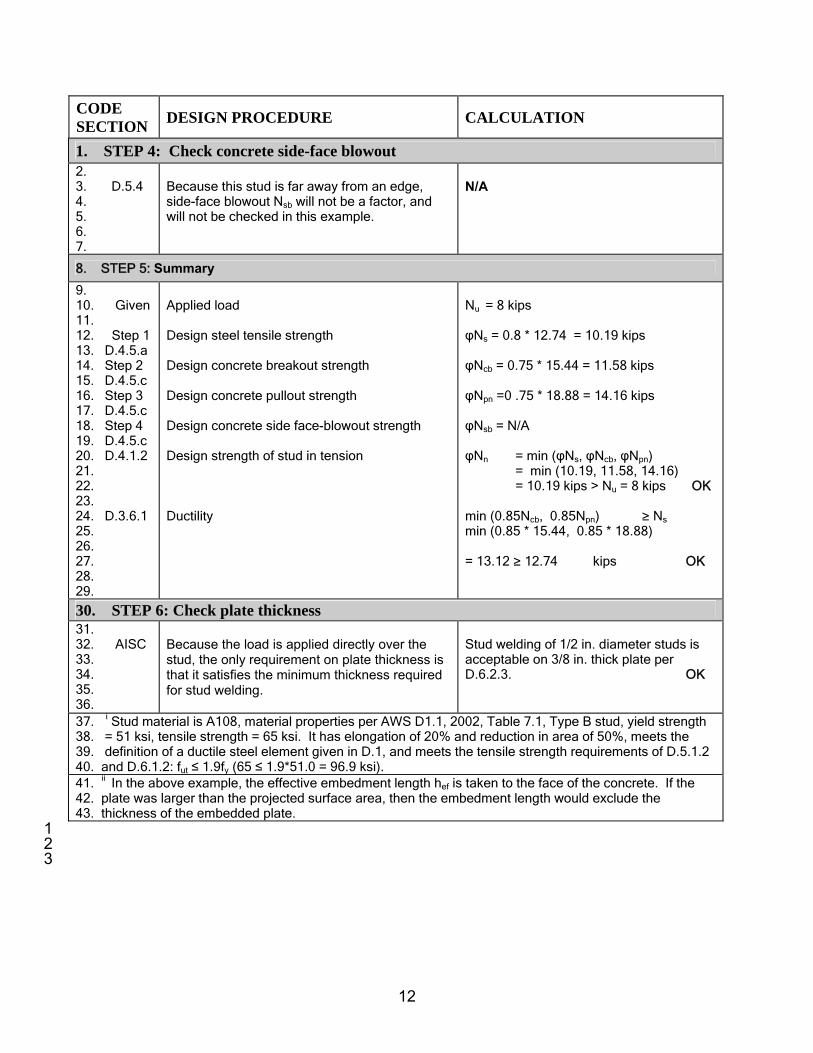
1. STEP 4: Check concrete side-face blowout 2. 3. D.5.4 4. 5. 6. 7.
Because this stud is far away from an edge, side-face blowout Nsb will not be a factor, and will not be checked in this example.
N/A
8. STEP 5: Summary
9. 10. Given 11. 12. Step 1 13. D.4.5.a 14. Step 2 15. D.4.5.c 16. Step 3 17. D.4.5.c 18. Step 4 19. D.4.5.c 20. D.4.1.2 21. 22. 23. 24. D.3.6.1 25. 26. 27. 28. 29.
Applied load Design steel tensile strength Design concrete breakout strength Design concrete pullout strength Design concrete side face-blowout strength Design strength of stud in tension Ductility
Nu = 8 kips φNs = 0.8 * 12.74 = 10.19 kips φNcb = 0.75 * 15.44 = 11.58 kips φNpn =0 .75 * 18.88 = 14.16 kips φNsb = N/A φNn = min (φNs, φNcb, φNpn) = min (10.19, 11.58, 14.16) = 10.19 kips > Nu = 8 kips OK min (0.85Ncb, 0.85Npn) ≥ Ns
min (0.85 * 15.44, 0.85 * 18.88) = 13.12 ≥ 12.74 kips OK
30. STEP 6: Check plate thickness 31. 32. AISC 33. 34. 35. 36.
Because the load is applied directly over the stud, the only requirement on plate thickness is that it satisfies the minimum thickness required for stud welding.
Stud welding of 1/2 in. diameter studs is acceptable on 3/8 in. thick plate per D.6.2.3. OK
37. i Stud material is A108, material properties per AWS D1.1, 2002, Table 7.1, Type B stud, yield strength 38. = 51 ksi, tensile strength = 65 ksi. It has elongation of 20% and reduction in area of 50%, meets the 39. definition of a ductile steel element given in D.1, and meets the tensile strength requirements of D.5.1.2 40. and D.6.1.2: fut ≤ 1.9fy (65 ≤ 1.9*51.0 = 96.9 ksi). 41. ii In the above example, the effective embedment length hef is taken to the face of the concrete. If the 42. plate was larger than the projected surface area, then the embedment length would exclude the 43. thickness of the embedded plate. 1 2 3

13
²
Example A2—Single stud, shear only 1 2 Design an embedment using a stud welded to an embedded plate. 3
4 Given: 5 Edge 6 c1 = 10 in. 7
c2 = 18 in. 8 h = 18 in. 9 Concrete 10
fc’ = 4000 psi 11 12 Stud material (A108) 13
fy = 51 ksi 14 fut = 65 ksi 15
16 Plate 17 Assume 3 x 3 x 3/8 in. thick 18 Fy = 36 ksi 19 20 Loads 21
Vu = 6 kips 22 23 Where Vu is the applied factored external load 24 using load factors from Appendix C of the code. 25 26 Assumptions: 27
• Concrete is cracked 28 • φ-factors are based on Condition B in D.4.5 of the code 29
(no supplementary reinforcement) 30 31 32 33 34 35 36 37 38 39 40 41 42 43 44 CODE SECTION DESIGN PROCEDURE CALCULATION
45. STEP 1: Determine required steel area of the stud 46. 47. D.4.1 48. 49. D.6.1.2 50. 51. D.3.6.1 52.
Equate the external factored load to the internal design strength and solve for the required steel area of the stud. Assume embedment will be designed as ductile in accordance with D.3.6.1 (in Step 2).
Equation No: φVn ≥ Vu (D-2) Vn = Vs = nAsefut (D-18) Ase,req = Vu/(φnfut)

14
CODE SECTION DESIGN PROCEDURE CALCULATION
1. D.4.5 2. 3. D.6.1 4. 5. 6. 7. 8. 9. 10. 11. 12. 13. D.6.1.2 14. 15. 16. 17. 18. 19.
Therefore: φ = 0.75 for shear loads. Design required area of stud using the steel strength provision. Effective Anchor dia. Area, Ase in.2 3/8 0.110 1/2 0.196 controls Calculate nominal shear capacity of the selected stud. Material properties are given. See Endnote 1. Check that D.6.1.2 is met. (See also Table 6, Appendix A for additional stud properties).
φ = 0.75 Ase,req = 6/(0.75 * 1 * 65) = 0.123 in.2 required Use one 1/2 in. diameter stud Ase = 0.196 in.2 > 0.123 in.2 OK Vs = nAsefut (D-18) = 1.0 * 0.196 * 65 = 12.74 kips fut =65 ≤ 1.9fy = 1.9 * 51 = 96.9 ksi ≤ 125 ksi OK
20. STEP 2: Determine required edge distance to prevent concrete breakout failure in 21. shear 21. 22. 23. 24. 25. 26. 27. D.3.6.1 28. 29. 30. 31. 32. 33. D.6.2.1 34. 35. 36. 37. 38. 39. 40.
41. D.6.2.3 42. 43. 44. 45. 46. 47. 48. 49. 50. 51.
Ensure that the embedment design is controlled by the strength of the embedment steel. The requirement for ductile design is given in D.3.6.1. For shear load this requires that: 0.85Vcb ≥ Asefut Calculate concrete breakout strength Vcb in shear for a single stud. Calculate projected area for a single stud. See figure above for illustration of Av0. Because edges are far enough away, Av and Av0 are equal. For cast-in headed studs, or headed bolts, that are welded to steel attachments having a minimum thickness equal to the greater of 3/8 in. or half of the anchor diameter, the basic concrete breakout strength Vb is determined using D.6.2.3. See definition in D.0 for limits on l.
0.85Vcb ≥ Asefut min Vcb = Asefut/0.85 = 0.196 * 65 / 0.85 = 14.99 kips
bV
Vcb V
AAV 76
0
ΨΨ= (D-20)
Av0 = 4.5c12 (D-22)
Av = Av0 Av/Av0 = 1.0
1.51
'c0
0.20b cfd)8(l/dV = lb (D-24)
l ≤ 8d0 Definition in D.0 Assume l = 2.5 in. (l/d0) = 2.5/.5 = 5.0 Vb = 8 * 5.0.2 * 0.5.5 * 4000.5 * c1
1.5 = 494 c1
1.5 lb = 0.494 c1
1.5 kips

15
CODE SECTION DESIGN PROCEDURE CALCULATION
1. 2. 3. 4. D.6.2.6 5. D.6.2.7 6. 7. 8. 9. 10. 11. 12. 13. 14. 15. 16. 17. 18. 19.
Modification factors for shear for: Edge effects ψ6 Cracked concrete ψ7 Concrete is cracked per problem statement. No additional supplementary steel is provided. Calculate Vcb using c1 = 10 in. provided
ψ6 = 1.0 ψ7 = 1.0
Vcb,req= 14.99 kips = 1.0 * 1.0 * 1.0 * 0.494 c1
1.5 = .494* c1
1.5 kips c1,req = 9.73 in. (required) < 10.0 in. (provided) OK Strength controlled by steel Vcb = 0.494 * 101.5 = 15.62 > 12.74 kips
20. STEP 3: Determine the required embedment length for the stud to prevent concrete 21. pryout failure 22. 23. D.6.3 24. 25. 26. D.3.6.1 27. 28. 29. 30. 31. 32. 33. D.6.3 34. 35. 36. 37. 38. 39. 40. 41. 42. D.5.2 43. 44. 45. 46. 47. 48. 49. D.5.2.2 50. 51. 52.
Determine the required effective embedment length to prevent pryout. Ductility requirements of D.3.6.1 shall be satisfied: 0.85 Vcp ≥ Vs Design required embedment depth, from the concrete pryout strength requirement. Assume hef > 2.5 in. Therefore, kcp = 2.0. Ncb is the required concrete breakout strength in tension. Calculate the required embedment depth of the anchor to prevent breakout. The approach is identical to that for tension used in Example 1. Because this is a single stud away from edges, modification factors are all 1. Basic concrete breakout strength for a single anchor in tension: k = 24 for cast-in headed studs. Assume hef < 11 in.
Vs = 12.74 kips (D-18) See Step 1 (Note: Same value as for tension Ns) 0.85 * Vcp ≥ Vs = 12.74 Vcp,req = 12.74/0.85 = 14.99 kips Vcp = kcpNcb (D-28) kcp = 2.0 Ncb,req = 14.99/2.0 = 7.50 kips - required
(D-4)
AN/AN0 = 1.0 Ψ2 = 1.0 Ψ3 = 1.0
Nb = 5.1' )( efc hfk (D-7)
= 5.1)4000(24 efh
bN
Ncb N
AAN 32
0
ΨΨ=

16
CODE SECTION DESIGN PROCEDURE CALCULATION
1. 2. 3. 4. 5. 6. 7. 8. 9. 10. 11. 12. 13. 14. 15. 16. 17. 18. 19. 20. 21. 22.
See Appendix A, Table 6, for stud head dimensions. Note that 0.312 in. is head thickness and 0.125 in. is burn off. Calculate Vcp using hef = 3.06 in.
= 1.52 5.1efh kips.
7.50 = 1.0 * 1.0 * 1.0 * (1.52) 5.1efh
hef,req = 2.90 in. required Use 1/2 in. x 3-1/2 in. long stud hef provided: hef = 3.50 - 0.312 - 0.125 = 3.06 in. > 2.90 OK Vcp = kcpNcb = 2.0 * 1.52 * 3.061.5 = 16.27 > 12.74 kips OK
23. STEP 4: Check pullout strength of stud to check head of the stud 24. 25. 26. 27. 28. 29. D.5.3 30. 31. D.5.3.4 32. 33. 34.
35. D.5.3.5 36. 37. 38. 39. 40. 41. 42. D.3.6.1 43. 44. 45. 46. 47. 48. 49. 50. 51.
Checking of stud head is required to develop the concrete breakout strength Ncb used to check concrete pryout. Procedure is the same as that used in Example A1. Calculate the nominal pullout strength Npn of the anchor in tension in accordance with D.5.3. Concrete is cracked per problem statement. Therefore, Ψ4 = 1.0. Bearing area is based on manufacturer data. (See Table 6 in Appendix A). Design embedment as ductile, in accordance with D.3.6.1: 0.85 Npn ≥ Ns Ns for this problem is calculated in the pryout section shown in Step 3.
Npn = Ψ4Np (D-14) Np = Abrg8fc’ (D-15) = 8 * 4 * Abrg = 32 Abrg kips Ψ4 = 1.0 Abrg = 0.589 in.2 Npn = 1 *32 * 0.589 = 18.8 kips 0.85Npn = 0.85*18.8 = 16 kips > Ns = 12.74 kips
Therefore ductile OK Use 1/2 in. diameter x 3 1/2 in. long
stud Specified 1/2 in. diameter anchor head dimension OK
52. STEP 5: Summary of design strength
17
CODE SECTION DESIGN PROCEDURE CALCULATION
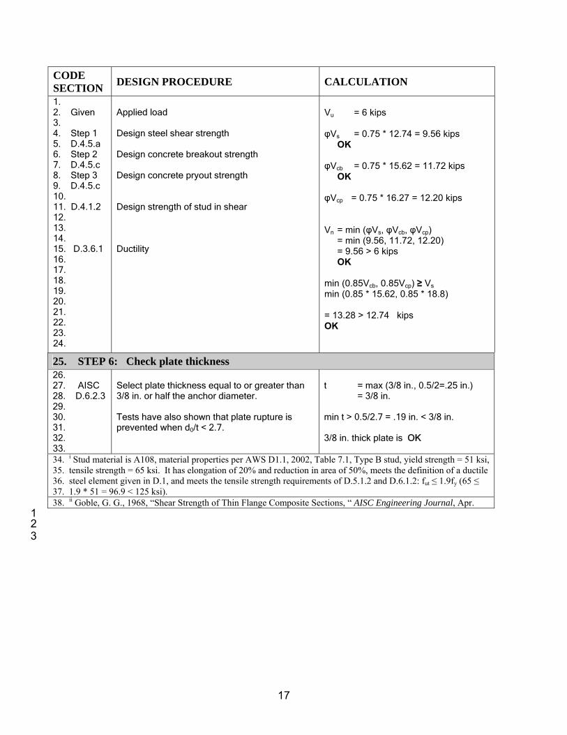
1. 2. Given 3. 4. Step 1 5. D.4.5.a 6. Step 2 7. D.4.5.c 8. Step 3 9. D.4.5.c 10. 11. D.4.1.2 12. 13. 14. 15. D.3.6.1 16. 17. 18. 19. 20. 21. 22. 23. 24.
Applied load Design steel shear strength Design concrete breakout strength Design concrete pryout strength Design strength of stud in shear Ductility
Vu = 6 kips φVs = 0.75 * 12.74 = 9.56 kips OK φVcb = 0.75 * 15.62 = 11.72 kips OK φVcp = 0.75 * 16.27 = 12.20 kips Vn = min (φVs, φVcb, φVcp) = min (9.56, 11.72, 12.20) = 9.56 > 6 kips OK min (0.85Vcb, 0.85Vcp) ≥ Vs min (0.85 * 15.62, 0.85 * 18.8) = 13.28 > 12.74 kips OK
25. STEP 6: Check plate thickness 26. 27. AISC 28. D.6.2.3 29. 30. 31. 32. 33.
Select plate thickness equal to or greater than 3/8 in. or half the anchor diameter. Tests have also shown that plate rupture is prevented when d0/t < 2.7.
t = max (3/8 in., 0.5/2=.25 in.) = 3/8 in. min t > 0.5/2.7 = .19 in. < 3/8 in. 3/8 in. thick plate is OK
34. i Stud material is A108, material properties per AWS D1.1, 2002, Table 7.1, Type B stud, yield strength = 51 ksi, 35. tensile strength = 65 ksi. It has elongation of 20% and reduction in area of 50%, meets the definition of a ductile 36. steel element given in D.1, and meets the tensile strength requirements of D.5.1.2 and D.6.1.2: fut ≤ 1.9fy (65 ≤ 37. 1.9 * 51 = 96.9 < 125 ksi). 38. ii Goble, G. G., 1968, “Shear Strength of Thin Flange Composite Sections, “ AISC Engineering Journal, Apr. 1 2 3

18
²
Example A3—Single stud, combined tension and shear 1 2 3 Design an embedment using a stud welded to an embedded plate. 4 5 6 Given: 7 Edge 8 c1 = 12 in. 9 c2 = 20 in. 10 h = 18 in. 11 12 Concrete 13
fc’ = 4000 psi 14 15 Stud material (A108) 16
fy = 51 ksi 17 fut = 65 ksi 18
19 Plate 20 3 x 3 x 3/8 in. thick 21 Fy = 36 ksi 22 23 Loads 24
Nu = 8 kips 25 Vu = 6 kips 26
27 Where Nu and Vu are the applied factored external loads 28 using load factors from Appendix C of the code. 29
30 Assumptions: 31
• Concrete is cracked 32 • φ-factors are based on Condition B in D.4.5 of the code 33
(no supplementary reinforcement) 34 35 36 37 38 39 40 41 42 43 44 45 46 47 48 49 50 51 52 53 54 55 56

19
CODE SECTION DESIGN PROCEDURE CALCULATION
1. STEP 1: Determine required steel area of the stud 2. 3. D.4.1.1 4. 5. 6. 7. D.5.1 8. D.5.1.2 9. 10. 11. 12. 13. D.3.6.1 14. 15. D.4.5 16.D.5.1.2/D.617. .1.2 18. 19. 20. 21. D.6.1 22. 23. 24. 25. 26. 27. 28.
29. D.7.3 30. 31. 32. 33. 34. 35. 36. 37. 38. 39. 40. 41. 42. 43. 44. 45. 46. 47. 48. 49. 50. 51. 52. 53.
Equate the external factored load to the internal design strength and solve for the required steel area of the stud. Use the tension provisions of D.5.1 to determine the required steel area for tension load. Ase,t = required steel area for tension load Assume embedment will be designed as ductile in accordance with D.3.6.1 (in Step 2). Therefore, φ = 0.80 for tension and 0.75 for shear. Steel material is ductile (See Endnote 1). Use the shear provisions of D.6.1 to determine the required steel area for shear load. Ase,v = required steel area for shear Add the area of steel required for tension to the area of steel required for shear. Total required area Ase,req = (Ase,t + Ase,v )/1.2 This assumes interaction between tension and shear, which will be checked in Step 8. Effective Anchor diameter area, Ase in.2 1/2 0.196 5/8 0.307 controls Calculate nominal steel strength Ns Calculate nominal steel strength Vs
Equation
No.
φNn ≥ Nu (D-1) Nn = Ns = nAse,tfut (D-3) Ase,t = Nu / (φnfut) = (8 /0.80 * 1.0 * 65) Ase,t = 0.154 in.2
φVn ≥ Vu (D-2) Vn = Vs = nAse,vfut (D-17) Ase,v = Vu/(φnfut) = 6/(0.75 * 1.0 * 65) = 0.123 in.2 Ase,req = (0.154 +
0.123)/1.2 = 0.231 in.2
Use one 5/8 in. diameter stud Ase = 0.307 in.2 > 0.231 in.2 OK Ns = nAsefut
= 1.0 * 0.307 * 65 = 19.96 kips Vs = nAsefut
= 1.0 * 0.307 * 65 = 19.96 kips

20
CODE SECTION DESIGN PROCEDURE CALCULATION
1 2. 3.
4. STEP 2: Determine required embedment length of the stud to prevent concrete 5. breakout failure in tension 6. 7. D.5.2 8. D.5.2.1 9. 10. 11. 12. 13. 14. 15. 16. 17. D.3.6.1 18. 19. 20. 21. 22. 23. 24. D.5.2.1 25. 26. 27. 28. 29. 30. D.5.2.5 31. D.5.2.6 32. D.5.2.7 33. 34. D.5.2.2 35. 36. 37. 38. 39. 40. 41. 42. 43. 44. 45. 46. 47. 48. 49. 50. 51 52. 53.
Calculate the required embedment depth for the stud to prevent concrete breakout failure. The depth will be selected so that the stud will be governed by the strength of the ductile steel element. This will produce a ductile embedment and justify the use of the φ-factor used above. The steel capacity is based on the selected stud diameter. The requirements for a ductile design are given in D.3.6.1. For tension load, this requires that 0.85*Ncb ≥ Ns Calculate concrete breakout strength for a single anchor For a single stud away from edge: Modification factors for: Edge effects Ψ2 Concrete cracking Ψ3 Ψcp, N applies to post installed anchors only k = 24 for cast-in-place stud. Assume hef < 11 in. Required embedment length hef,req
In this example, the total length of the stud L is equal to the embedment length plus the head thickness plus allowance for weld burn off. Head dimensions are given by the manufacturer. Typical values are given in Table 6 in Appendix 1. Calculate Ncb using hef,provided
From Step 1 Ns = 19.96 kips (D-3)
0.85 * Ncb,req ≥ Ns. Ncb,req = Ns/0.85 = 19.96/0.85 = 23.48 kips
bNcpN
Ncb N
AAN ,32
0
ΨΨΨ= lb (D-4)
AN/AN0 = 1.0
Ψ2 = 1.0 Ψ3 = 1.0 Ψcp, N = N/A for studs Nb = 5.1' )( efc hfk lb (D-7)
= 5.1)4000(24 efh
= 1.52 5.1efh kips
23.48 = 1.0 * 1.0 * 1.0 * 1.52 5.1,reqefh
hef,req = 6.20 in. required Use 5/8 in. x 6-3/4 in. long stud hef,provided = 6.75 - .312 - .187 + .375 in. = 6.63 in. > 6.20 in. OK c1 = 12 in. > 1.5 * hef = 1.5 * 6.63 = 9.94 in. edge distance has no effect.

21
CODE SECTION DESIGN PROCEDURE CALCULATION
1. 2. 3. 4. 5. 6. 7.
Ncb = 1.52 * 6.631.5 = 25.95 kips
8. STEP 3: Check pullout strength of stud 9. 10. 11.
12. D.5.3 13. 14. 15. D.5.3.4 16. 17. 18.
19. D.5.3.5 20. 21. 22. 23. 24.
25. D.3.6.1 26. 27. 28. 29. 30. 31. 32. 33. 34. 35.
Stud head is required to develop the concrete breakout strength Ncb. Procedure is similar to that used in Example A1. Calculate the nominal pullout strength Npn of the stud in tension in accordance with D.5.3.
Concrete is cracked per problem statement.
Therefore, Ψ4 = 1.0. Bearing area is based on manufacturer data. (Appendix A, Table 6).
Design embedment as ductile, in accordance with D.3.6.1:
0.85 Npn ≥ Ns Ns for this problem is calculated in Step 1.
Npn = Ψ4Np (D-14) Np = Abrg8fc’ (D-15) = Abrg * 8 * 4 = 32 Abrg kips
Ψ4 = 1.0 Abrg = 0.92 in.2 Table 6 Npn = 1.0 * 32 * 0.92 = 29.44 kips 0.85Npn = 0.85 * 29.44 = 25.02 kips > Ns = 19.96 kips Therefore ductile 5/8 in. diameter x 6-3/4 in. long stud
OK
36. STEP 4: Check concrete side-face blowout 37. 38. D.5.4 39. RD.5.4 40. 41. 42. 43. 44. 45. 46. 47. 48. 49. 50. 51.
Because this stud is relatively far away from an edge, side-face blowout will not be a factor. According to the commentary, side-face blowout is not a concern if c > 0.4hef. In this example: hef = 6.63 in.; 0.4hef = 0.4 * 6.63 = 2.6 in. c = 12 in. > 2.6 in. Because c > 0.4hef, side-face blowout calculation is not required. The calculation will be done to illustrate the method. See also Table 7 in Appendix A.
'160 cbrgsb fAcN = (D-16)
c = 12 in. Abrg = 0.92 in.2 Table 6 fc’ = 4000 psi Nsb = 160 * 12 * 0.920.5 * 40000.5 = 116.5 kips 0.85 Nsb= 99.0 kips > Ns = 19.96 kips OK 5/8 in. diameter x 6-3/4 in. long stud
OK

22
CODE SECTION DESIGN PROCEDURE CALCULATION
1. STEP 5: Determine required edge distance to prevent concrete breakout failure in shear
2. 3. D.3.6.1 4. 5. 6. 7. 8. 9. 10. 11. 12. 13. D.6.2.1 14. 15. 16. 17. 18. 19. 20. 21. D.6.2.3 22. 23. 24. 25. 26. 27. 28. 29. 30. 31. 32. D.6.2.6 33. D.6.2.7 34. 35. 36. 37. 38. 39. 40. 41. Step 1 42. 43. 44. 45. 46.
Ensure that the embedment design is controlled by the strength of the embedment steel. The requirement for ductile design is given in D.3.6.1. For shear load this requires that: 0.85Vcb ≥ Asefut Calculate concrete breakout strength Vcb in shear for a single stud. Calculate projected area for a single stud. See figure above for illustration of Av0. Because edges are far enough away, Av and Av0 are equal. For cast-in headed studs or headed bolts that are welded to steel attachments having a minimum thickness equal to the greater of 3/8 in. or half of the anchor diameter, the basic concrete breakout strength Vb is determined using D.6.2.3. See definition in D.0 for limits on ℓ. Modification factors for shear for: Edge effects, ψ6 Cracked concrete, ψ7 Concrete is cracked per problem statement. No additional supplementary steel is supplied. Steel strength in shear Vs. Calculate Vcb using c1 = 12 in. provided
0.85Vcb ≥ Asefut Vcb,req = Asefut/0.85 = 0.307 * 65 / 0.85 = 23.48 kips
(D-20)
Av0 = 4.5c12 (D-22)
Av = Av0 Av/Av0 = 1.0
5.11
'0
2.00 )/(8 cfddlV cb =
(D-24) ℓ/d0 = 6.63/0.625 = 10.61 > 8.0 Use ℓ/d0 = 8.0 D.0 Vb = 8 * 80.2 * 0.6250.5 * 40000.5 * c1
1.5 = 606 c1
1.5 lbs = 0.606 c1
1.5 kips ψ6 = 1.0 ψ7 = 1.0 23.48 = 1.0 * 1.0 * 1.0 * 0.606 c1,req
1.5 c1,req = 11.45 in. < 12.0 in. OK Strength controlled by steel Vs = 19.96 kips Vcb = 0.606 c1
1.5 = 0.606 (12)1.5
= 25.19 kips
bV
Vcb V
AAV 76
0
ΨΨ=

23
CODE SECTION DESIGN PROCEDURE CALCULATION
1. STEP 6: Check concrete pryout failure 2. 3. D.6.3 4. 5. 6. 7. 8. D.3.6.1 9. 10. 11. 12. 13. 14. 15. 16. D.6.3 17. 18. 19. 20. 21. 22.
Pryout strength of the stud is checked using D.6.3. For an anchor or stud designed for tension, this will not govern. The calculations are for illustration of the method. Ductility requirements of D.3.6.1 shall be satisfied: 0.85 Vcp ≥ Vs Ncb is calculated in Step 2
0.85 * Vcp ≥ Vs. Vcp,req = Vs/0.85 = 19.96/0.85 = 23.5 kips Vcp = kcpNcb (D-28) kcp = 2.0 Ncb = 25.95 kips Vcp = 2 * 25.95 = 51.9 kips >> 23.5 kips OK 5/8 in. diameter x 6-3/4 in. long stud
is OK
23. STEP 7: Summary 24. 25. D.4.1.2 26. 27. 28. 29. Step 1 30. D.4.5.a 31. Step 2 32. D.4.5.c 33. Step 3 34. D.4.5.c 35. Step 4 36. D.4.5.c 37. D.4.1.2 38. 39. 40. 41. 42. 43. 44. Step 1 45. D.4.5.a 46. Step 2 47. D.4.5.c 48. Step 3 49. D.4.5.c 50. D.4.1.2 51. 52.
TENSION Applied load Steel strength Concrete breakout strength Concrete pullout strength Concrete side face-blowout strength Design strength of stud, tension SHEAR Applied load Steel strength Concrete breakout strength Concrete pryout strength Design strength of stud, shear
Nu = 8 kips φNs = 0.80 * 19.96 = 15.97 kips φNcb = 0.75 * 25.95 = 19.46 kips φNpn =0 .75 * 29.44 = 22.08 kips φNsb = 0.75 * 116.5 = 87.40 kips φNn = min (φNs ,φNcb ,φNpn, φNsb ) = min (15.97, 19.46, 22.08, 87.40) = 15.97 kips > Nu = 8 kips OK Vu = 6 kips φVs = 0.75 * 19.96 = 14.97 kips φVcb = 0.75 * 25.19 = 18.89 kips φVcp =0 .75 * 51.9 = 38.9 kips φVn = min (φVs ,φVcb ,φVcp) = min (14.97, 18.89, 38.9) = 14.97 kips > Vu = 6 kips OK

24
CODE SECTION DESIGN PROCEDURE CALCULATION
1. 2. D.3.6.1 3. 4. 5. 6. 7. 8. 9. 10. 11. 12.
Ductility tension Shear
min (0.85Ncb, 0.85Npn, 0.85 Nsb) ≥ Ns
min (0.85 * 25.95, 0.85 * 18.88, 0.85 * 116.5) min (22.06, 16.05, 99.03) = 22.06 > Ns = 19.96 kips OK min (0.85Vcb, 0.85Vcp) > Vs min (0.85*25.19, 0.85*51.9) min (21.41, 44.12) = 21.41 > Vs = 19.96 kips OK
13. STEP 8: Check interaction of tension and shear forces 14. 15. 16. D.7 17. D.7.1 18. 19. 20. D.7.2 21. 22. 23. D.7.3 24. 25. 26. 27.
Vu/φVn > 0.2 Full strength in tension shall not be permitted. Nu/φNn > 0.2 Full strength in shear shall not be permitted.
2.1≤+n
u
n
u
VV
NN
φφ
Vu/φVn = 6.0/14.97 = 0.40 > 0.2 Nu/φNn = 8.0/15.97 = 0.50 > 0.2
90.040.050.0 =+=+n
u
n
u
VV
NN
φφ (D-3)
0.90 < 1.2 OK
28. STEP 9: Calculate minimum plate thickness 29. 30. D.6.2.3 31. 32. 33. 34. 35. 36.
Select plate thickness equal to or greater than 3/8 in. or half the anchor diameter. Tests have also shown that plate rupture is prevented when d0/t < 2.7.
t = max (3/8 in., 0.5/2=.25 in.) = 3/8 in. treq > 0.5/2.7 = 0.19 in. < 3/8 in. 3/8 in. thick plate is OK
37. i Stud material is A108, material properties per AWS D1.1, 2002, Table 7.1, Type B stud, yield strength = 51 ksi, 38. tensile strength = 65 ksi. It has elongation of 20% and reduction in area of 50%, meets the definition of a ductile 39. steel element given in D.1, and meets the tensile strength requirements of D.5.1.2 and D.6.1.2: fut ≤ 1.9fy (65 ≤ 1.9 40. * 51.0 = 96.9 ksi). 41. ii Goble, G. G., 1968, “Shear Strength of Thin Flange Composite Sections,” AISC Engineering Journal, Apr.

25
Example A4 – Single bolt, combined tension and shear 1 2 Design an embedment using a high-strength bolt, F1554 Gr. 105 (AB1051). 3 4 Given: 5 Edge 6 c1 = 24 in. 7 c2 = 24 in. 8 h = 36 in. 9 Concrete 10 fc’ = 4000 psi 11
12 Bolt material (AB105) 13 fy = 105 ksi 14 fut = 125 ksi 15
16 Plate 17
3/8 in. thick 18 Fy = 36 ksi 19 20 Loads 21
Nu = 40 kips 22 Vu = 20 kips 23
24 Where Nu and Vu are the applied factored external loads using load factors from Appendix C of the code. 25 26 Assumptions: 27
• Concrete is cracked 28 • φ-factors are based on Condition B in D.4.5 of the code 29
(no supplementary reinforcement) 30 31 CODE SECTION DESIGN PROCEDURE CALCULATION
32. STEP 1: Determine required steel area of the bolt 33. 34. 35 36. D.4.1.1 37. 38. D.5.1.2 39. 40. 41. 42. 43. D.3.6.1 44. D.4.5.a 45. 46. 47. 48. 49. D.6.1 50. D.4.5.a 51. D.6.1.2 52. 53.
Equate the external factored load to the internal design strength and solve for the required steel area of the bolt. Use the tension provisions of D.5.1 to determine the required steel area for tension load. Ase,t = required steel area for tension load. Assume embedment will be designed as ductile in accordance with D.3.6.1 (in Step 2). Therefore, φ = 0.80 for tension and 0.75 for shear. Assume bolt is far away from an edge. Use the shear provisions of D.6.1 to determine the required steel area for shear load. Ase,v = required steel area for shear load.
Equation
No. φNn ≥ Nu (D-1) Nn = Ns = nAse,tfut (D-3) Ase,t = Nu /(φnfut) Ase,t = 40/(0.8 * 1 * 125) = 0.40 in.2 φVn ≥ Vu (D-2) Vn = Vs = n0.6Ase,vfut (D-18) Ase,v = Vu/(n0.6φfut ) Ase,v = 20/(1.0 * 0.6 * 0.75 * 125) = 0.36 in.2

26
CODE SECTION DESIGN PROCEDURE CALCULATION
1. 2. 3. 4. D.7.3 5. 6. 7. 8. 9. 10. 11. 12. 13. 14. 15. 16. 17. 18. 19. 20. 21. 22. 23. 24.
Add the area of steel required for tension to the area of steel required for shear. Total required area, Ase = (Ase,t + Ase,v )/1.2 This assumes interaction between tension and shear, which will be checked in Step 8. Effective Anchor diameter area, Ase in.2 1.0 0.606 1.125 0.763 controls Calculate nominal steel strength Ns in tension. Calculate nominal steel strength Vs in shear.
Ase = (0.40 + 0.36)/1.2 = 0.64 in.2 Use one 1-1/8 in. diameter headed
bolt Ase = 0.76 in.2 > 0.64 in.2 OK Ns = nAsefut = 1 * 0.76 * 125 = 95.0 kips Vs = n 0.6 Asefut = 1 * 0.6 * 0.76 * 125 = 57.0 kips
25. STEP 2: Determine required embedment length for the bolt to prevent concrete 26. breakout failure in tension 27. 28. D.5.2 29. 30. 31. 32. 33. 34. 35. 36. 37. 38. D.3.6.1 39. 40. 41. 42. 43. 44. 45. 46. 47. 48. 49. D.5.2.1 50. 51. 52. 53.
Calculate the required embedment depth for the bolt to prevent concrete breakout failure. The depth will be selected so that the anchor will be governed by the strength of the ductile steel element. This will produce a ductile embedment and justify the use of the φ-factor used above. The steel capacity is based on the selected anchor diameter. Use Ns to determine required hef. The requirements for a ductile design are given in D.3.6.1. For tension load, this requires that: 0.85 * Ncb ≥ Ns Calculate concrete breakout strength for a single bolt For a single bolt away from edge:
From Step 1 Ns = 95.0 kips 0.85 * Ncb,≥ Ns. Ncb,req = Ns/0.85 = 95.0/.85 = 111.8 kips
bNcpN
Ncb N
AA
N ,320
ΨΨΨ= (D-4)
AN/AN0 = 1.0

27
CODE SECTION DESIGN PROCEDURE CALCULATION
1. 2. 3. D.5.2.5 4. D.5.2.6 5. D.5.2.7 6. 7. 8. 9. 10. 11. 12. 13. 14. 15. 16. 17. 18. 19. 20. 21. 22. 23. 24. 25. 26. 27. 28. 29. 30. 31. 32. 33. 34. 35. 36.
Modification factors for: Edge effects Ψ2 Concrete cracking Ψ3 Ψcp,N applies to post-installed anchors only Basic concrete breakout strength: k = 24 for cast-in-place anchors Determine the required effective embedment depth hef,req Determine bolt length L Calculate Ncb using hef, provided Note: For 11 in. ≤ hef ≥ 25 in., the basic concrete breakout strength Nb can alternatively be calculated using Eq. (D-8) that yields larger loads. This was neglected in this example.
Ψ2 = 1.0 Ψ3 = 1.0 Ψcp,N = N/A for bolts Nb = 5.1' )( efc hfk (D-7)
= 5.1)4000(24 efh
= 1.52 5.1efh kips.
bN
Ncb N
AAN 32
0
ΨΨ= (D-4)
111.8 = 1.0 * 1.0 * 1.0 * 1.52 5.1efh
hef,req = 17.57 in. L = 17.57 + 0.75 (thickness of head) = 18.32 in. Use 18.5 in. Use 1-1/8 in. diameter, F1554 Gr105 bolt embedded 18.5 in. into the concrete. hef,provided = 18.5 - .75 = 17.75 in. > 17.57 in. OK Ncb = 1.52 * 17.751.5 = 113.7 kips
37. STEP 3: Check pullout strength of bolt 38. 39. D.5.3 40. 41. 42. 43. 44. 45. 46. 47. D.5.3.5 48. 49. 50. 51. 52. 53.
Procedure is the same as that used in Example A1. Calculate the pullout strength of the bolt in tension in accordance with D.5.3. Calculate pullout strength Concrete is cracked per problem statement. Ψ4 = 1.0 ASTM F 1554 recommends a heavy hex head and washer. Appendix A, Table 4(c), Abrg = 1.85 in.2
Npn = Ψ4Np (D-14) Np = Abrg8fc’ (D-15) = Abrg * 8 * 4 = 32 Abrg Ψ4 = 1.0

28
CODE SECTION DESIGN PROCEDURE CALCULATION
1. 2. 3. 4. 5. 6. 7. 8. 9. 10. D.3.6.1 11. 12. 13. 14. 15. 16. 17. 18. 19. 20. 21. 22. 23. 24. 25. 26. 27. 28. 29. 30. 31. 32. 33. 34. D.3.6.1 35. 36. 37. 38. 39. 40. 41. 42. 43. 44. 45.
For this combination of steel strength and concrete strength, the anchor head alone is not sufficient to develop the required bearing strength. Find required net bearing area. Design embedment as ductile in accordance with D.3.6.1. .85 Npn ≥ Ns Find the total area of bearing surface. See Appendix A, Table 4 for anchor head areas. Design a washer to meet the required bearing area. From Table 5 we can see that the SAE washers will not work, and U.S. standard washers seem too thin. Try a square plate. Calculate Npn using Abrg, provided Check ductility, 0.85Npn ≥ Ns According to D.5.2.8, when adding a washer at the head of an anchor, it is permitted to calculate the projected area of the failure surface by projecting the failure surface outward 1.5hef from the effective perimeter of the washer. Therefore, the concrete breakout strength can be revised.
Npn = 1.0 * 32 * 1.85 = 59.2 kips < Ns, 95 kips 0.85Npn = Ns = 95 kips (Ns from Step 1) Npn,req = 95/0.85 = 111.8 kips 111.8 = 32 Abrg Abrg,req = 111.8/32 = 3.49 in.2 AD = 0.99 in.2 anchor areaAtotal,req = 3.49 + 0.99 = 4.48 in.2 For 1-1/8 in. bolt, hex head area is: AH = 2.85 in.2 areq = 4.48 – 2.85 = 1.63 in.2. Use a square plate 2-1/4 in. each side. Awasher = 2.252 = 5.06 in.2 > 4.48 in.2 OK Abrg,provided = 5.06 – 0.99 = 4.07 in.2 > 3.49 in.2
OK Npn = 1.0 * 32 * 4.07 = 130.24 kips 0.85Npn = 0.85 * 130.24 = 110.7 kips > Ns, 95 kips Use 1-1/8 in. diameter AB 105 bolt, embedded 18.5 in., with a square washer 2-1/4 in. sides and 3/8 in. thick.
46. STEP 4: Check concrete side-face blowout 47. 48. D.5.4 49. 50. 51.
Because this anchor is far away form an edge, side-face blowout will not be a factor, and will not be checked in this example.
29
CODE SECTION DESIGN PROCEDURE CALCULATION
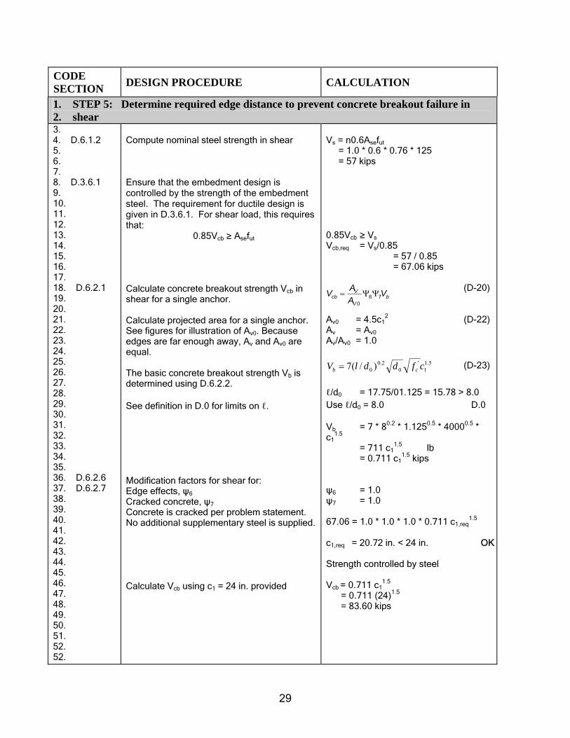
1. STEP 5: Determine required edge distance to prevent concrete breakout failure in 2. shear 3. 4. D.6.1.2 5. 6. 7. 8. D.3.6.1 9. 10. 11. 12. 13. 14. 15. 16. 17. 18. D.6.2.1 19. 20. 21. 22. 23. 24. 25. 26. 27. 28. 29. 30. 31. 32. 33. 34. 35. 36. D.6.2.6 37. D.6.2.7 38. 39. 40. 41. 42. 43. 44. 45. 46. 47. 48. 49. 50. 51. 52. 52.
Compute nominal steel strength in shear Ensure that the embedment design is controlled by the strength of the embedment steel. The requirement for ductile design is given in D.3.6.1. For shear load, this requires that: 0.85Vcb ≥ Asefut
Calculate concrete breakout strength Vcb in shear for a single anchor. Calculate projected area for a single anchor. See figures for illustration of Av0. Because edges are far enough away, Av and Av0 are equal. The basic concrete breakout strength Vb is determined using D.6.2.2. See definition in D.0 for limits on ℓ. Modification factors for shear for: Edge effects, ψ6 Cracked concrete, ψ7 Concrete is cracked per problem statement. No additional supplementary steel is supplied. Calculate Vcb using c1 = 24 in. provided
Vs = n0.6Asefut = 1.0 * 0.6 * 0.76 * 125 = 57 kips 0.85Vcb ≥ Vs Vcb,req = Vs/0.85 = 57 / 0.85 = 67.06 kips
(D-20)
Av0 = 4.5c12 (D-22)
Av = Av0 Av/Av0 = 1.0
5.11
'0
2.00 )/(7 cfddlV cb = (D-23)
ℓ/d0 = 17.75/01.125 = 15.78 > 8.0 Use ℓ/d0 = 8.0 D.0 Vb = 7 * 80.2 * 1.1250.5 * 40000.5 * c1
1.5 = 711 c1
1.5 lb = 0.711 c1
1.5 kips ψ6 = 1.0 ψ7 = 1.0 67.06 = 1.0 * 1.0 * 1.0 * 0.711 c1,req
1.5 c1,req = 20.72 in. < 24 in. OK Strength controlled by steel Vcb = 0.711 c1
1.5 = 0.711 (24)1.5
= 83.60 kips
bV
Vcb V
AAV 76
0
ΨΨ=

30
CODE SECTION DESIGN PROCEDURE CALCULATION
1. STEP 6: Check concrete pryout failure 2. 3. D.6.3 4. 5. 6. 7. 8. 9. 10.
For a bolt designed for tension, as in Step 2, concrete pryout failure will not govern, and hence, this step is not required. Vcp is calculated for illustration. Ncb is calculated in Step 2.
Vcp = kcpNcb (D-28)kcp = 2.0 Ncb = 113.7 kips Vcp = 2 * 113.7 = 227.4 kips >> 95 kips
11. STEP 7: Summary 12. 13. D.4.1.2 14. 15. 16. 17. Step 1/ 18. D.4.5.a Step 2/D.4.5.c 20. Step 3/D.4.5.c 22. Step 4/D.4.5.c 23. 24. 25. 26. 27. D.4.1.2 28. 29. 30. Step 1/D.4.5.a 32. Step 2/D.4.5.c 34. Step 3/D.4.5.c 36. 37. 38. 39. 40. D.3.6.1 41. 42. 43. 44. 45. 46. 47. 48. 49. 50.
TENSION Applied load Steel strength Concrete breakout strength Concrete pullout strength Concrete side face-blowout strength Design strength of stud, tension SHEAR Applied load Steel strength Concrete breakout strength Concrete pryout strength Design strength of stud, shear Ductility Tension Shear
Nu = 40 kips φNs = 0.80 * 95.0 = 76.0 kips φNcb = 0.75 * 113.7 = 85.3 kips φNpn =0 .75 * 130.24 = 97.68 kips N/A φNn = min (φNs, φNcb, φNpn )
= min (76.0, 85.3, 97.68) = 76.0 kips > Nu = 40 kips OK Vu = 20 kips φVs = 0.75 * 57.0 = 42.75 kips φVcb = 0.75 * 83.60 = 62.70 kips φVcp =0 .75 * 227.4 = 170.55 kips φVn = min (φVs, φVcb, φVcp) = min (42.75, 62.70, 170.55) = 42.75 kips > Vu = 20 kips OK min (0.85Ncb, 0.85Npn, 0.85 Nsb) ≥ Ns
min (0.85 * 113.7, 0.85 * 130.24, N/A) min (96.65, 110.70) = 96.65 > Ns = 95.0 kips OK min (0.85Vcb, 0.85Vcp) > Vs min (0.85 * 83.60, 0.85 * 227.4) min (71.06, 193.29) = 71.06 > Vs = 57.0 kips OK

31
CODE SECTION DESIGN PROCEDURE CALCULATION
1. STEP 8: Check interaction of tension and shear forces 2. 3. D.7 4. D.7.1 5. 6. 7. 8. D.7.2 9. 10. 11. 12. 13. 14. 15. 16. 17. 18. 19. 20. 21.
Vu/φVn > 0.2 Full strength in tension shall not be permitted Nu/ φNn > 0.2 Full strength in shear shall not be permitted
Vu/φVn = 20/42.75 = 0.47 > 0.2 (D-30) Nu/ φNn = 40/76.0 = 0.53 > 0.2 (D-30) 0.53 + 0.47 = 1.00 < 1.2 OK
22. STEP 9: Calculate minimum plate thickness 23. 24. AISC 25. 26. 27.
Select plate thickness using the appropriate steel code. This step is not included in this example.
28. i ASTM F 1554-00 specification, Grade 105, Class 1A, bolt material will be used. Bolt identification is 29. (AB105) with a tensile strength in the range of 125 to 150 ksi, and minimum yield strength of 105 ksi for 1/4 to 30. 3 in. diameters. Reductions in area requirements vary. For anchor diameters < 2 in., elongation in 2 in. is 15%, 31. and reduction in area is 45% and meets the definition of a ductile steel element given in D.1. Also, max fut = 1.4 32. fy. According to D.6.1.2, fut shall be ≤ 1.9 fy or 125, 000 psi. See also Table 1 for other materials.
2.1≤+n
u
n
u
VV
NN
φφ

32
Example B1(a)—Four-stud embedded plate, tension only, wide spacing 1 2 Design an embedment with four welded studs and an embedded plate for a 3 x 3 x 3/16 in. A501 structural tube 3 attachment where anchors are spaced 3hef apart. 4 5 Given: 6
Concrete edges 7 c = c1 = c2 = 15 in. 8 h = 18 in. 9 10 Concrete material 11 fc
’ = 4,000 psi 12 13 Stud material (A29/A108)i 14 fy = 51 ksi 15 fut = 65 ksi 16 17 Plate 18 Fy = 36 ksi 19 20 Load 21 Nu = 28 kips 22
23 Where Nu is the applied factored external load using 24 load factors from Appendix C of the code. The wide spacing 25 indicates that each of the four anchors develops 26 full tensile capacity. 27 28 Assumptions: 29
• Concrete is cracked 30 • φ-factors are based on Condition B in D.4.5 of the code 31
(no supplementary reinforcement) 32 • Ductile embedment design in accordance with D.3.6.1. 33
34 CODE
SECTION DESIGN PROCEDURE CALCULATION
35. STEP 1: Determine the required stud diameter 36. 37. 38 D.4.1.1 39. 40. 41. 42. 43. 44. D.4.5 45. 46. 47. 48. 49. D.5.1 50. 51. 52. 53.
Equate internal design strength (φNn) to the external factored load (Nu). In a ductile design, the internal strength (Nn) is controlled by the steel strength of the stud (Ns). The required steel strength of the stud (Ns,req) is multiplied by φ = 0.80 for tension because the embedment and the steel stud is ductile and the load factors are based on Appendix C of the code. Solve for the required steel area for a single stud (Ase,req). Effective Anchor diameter area, Ase in.2
Equation No. φNn ≥ Nu (D-1) Nn = Ns= nAsefut 0.80 * Ns,req ≥ 28 Ns,req = 28/0.8 = 35.0 kips Ns,req = nAse,req fut (D-3) 35.0 = 4 * Ase,req * 65 Ase,req = 35.0/(4 * 65) = 0.13 in.2 required Use 1/2 in. diameter studs Ase = 0.196 > 0.13 in.2 OK

33
CODE SECTION DESIGN PROCEDURE CALCULATION
1. 2. 3. 4. D.5.1 5. 6. 7.
3/8 0.110 1/2 0.196 controls Determine the nominal tensile strength Ns of 4-1/2 in. diameter studs.
Ns = nAsefut (D-3) = 4 * 0.196 * 65 = 51.0 kips
8. STEP 2: Determine the minimum embedment length and spacing for the studs to prevent 9. concrete breakout failure in tension 10. 11. 12. 13. D.3.6.1 14. 15. 16. 17. 18. 19. 20. D.3.6.1 21. 22. 23. 24. D.5.2 25. 26. 27. D.5.2.1 28. 29. 30. 31. 32. D.5.2.4 33. D.5.2.5 34. 35. 36. 37. 38. 39. 40. 41. 42. D.5.2.6 43. 44. D.5.2.7 45. 46. D.5.2.2 47. 48. 49. 50. 51. 52. 53. D.5.2
Ensure steel strength controls: To prevent concrete breakout failure in tension the required design concrete breakout tensile strength (φ Ncbg,req) has to be greater than or equal to the nominal tensile strength of the embedment steel (Ns). The design concrete breakout strength shall be taken as 0.85 times the nominal strength. Ncbg is the nominal concrete breakout strength in tension of a group of anchors. AN is not calculated because it is assumed that spacing is not limited. Therefore, only the ratio AN/AN0 is needed. Modification factors are all 1.0 for: Eccentricity effects Ψ1
Edge effects Ψ2
cmin = 15 in. per problem statement. Edge effects factor Ψ2 will be 1.0 as long as cmin ≥ 1.5 * hef or hef ≤ cmin/1.5. Therefore, the embedment hef needs to be less than 15/1.5 = 10 in. to ensure no reduction due to edge distance. Concrete cracking Ψ3. Concrete is cracked per problem statement. Ψcp,N is not used for cast-in-place anchors Nb is the basic concrete breakout strength in tension of a single anchor in cracked concrete. Assume the embedment will be less than 11 in., and use Eq. (D-7). For cast-in-place anchors use k = 24. Ncbg is the nominal concrete breakout strength in
φ * Ncbg req≥ Ns Ns = 51.0 kips Step 1 0.85 * Ncbg,req ≥ Ns Ncbg,req ≥ 51/.85 Ncbg,req = 60.0 kips
Ncbg = bNcpN
N NAA
,3210
ΨΨΨΨ (D-5)
AN = 4 * AN0 AN/AN0 = 4 Ψ1 = 1.0 Ψ2 = 1.0 Ψ3 = 1.0 Ψcp,N = N/A for studs
Nb = 5.1'
efc hfk (D-7)
Nb = 24(4,000)0.5(hef)
1.5 = 1.52(hef)
1.5 kips

34
CODE SECTION DESIGN PROCEDURE CALCULATION
1. 2. 3. 4. 5. 6. 7. 8. 9. 10. 11. 12. 13. 14. 15. 16. 17. 18. 19. 20. D.5.2.1 21. 22. 23. 24. 25. 26. 27. 28. D.5.2 29. 30. 31. D.5.2.1 32. 33. 34. 35. D.5.2.1 36. 37. 38. 39. D.5.2.1 40. 41. 42. 43. 44. 45. 46. 47. 48. 49. 50. 51. 52. 53. 54.
tension of a group of anchors. Calculate the minimum required effective embedment depth hef by setting Ncbg equal to Ncbg,req. Determine the total length L of the stud: The total required length L of the stud is equal to the required effective embedment depth hef plus the head thickness, plus allowance for burn off, (minus the plate thickness, which is conservatively ignored in this problemii). Typical values for head thickness, and burn off are provided in Table 6 of Appendix A. Determine the spacing s: Assume no limits on spacing. Space anchors at 3 times hef. Determine the actual concrete breakout failure (Ncbg) using the actual embedment and spacing. Ncbg is the nominal concrete breakout strength in tension of a group of anchors. Determine AN Determine ANO The ratio of AN/ANO is limited to 4. The embedment is less than 11 in. Therefore, Eq. (D-7) is used to calculate the basic concrete breakout strength. Also, because the embedment is less than 10 in., ψ2 is 1.0 as assumed previously.
Ncbg = bN
N NAA
3210
ΨΨΨ (D-5)
= 4 * 1.0 * 1.0 *1.0 * 1.52 * (hef)1.5
= 6.08 * (hef)1.5
6.08 * (hef)
1.5 = 60.0 kips hef req = 4.6 in. Lreq = hef + head thickness + burn off = 4.6 + 0.312 + 0.125 = 5.04 in. Use 4-1/2 in. diameter x 5-1/4 in. long studs. hef,provided = 5.25 – 0.312 – 0.125 (burn
off) = 4.81 in. Spacing required between anchors is: 3 * 4.81 = 14.43 in. Use spacing s = 15 in.
Ncbg = bN
N NAA
3210
ΨΨΨ (D-5)
AN = (3 hef + s)2 = (3 * 4.81 + 15)2 = 866.1 in.2 ANO = 9 * hef
2 (D-6) = 9 * (4.81)2 = 208.2 in.2 AN/ANO = 866.1/208.2 = 4.16 > 4.0 Use 4.0 Nb = 1.52 (hef)
1.5 (D-7) = 1.52 * (4.81)1.5 = 16.03 kips Ncbg = 4 * 1.0 * 1.0 * 1.0 * 1.0 * 16.03 = 64.1 kips

35
CODE SECTION DESIGN PROCEDURE CALCULATION
1. 2. 3. 4.
0.85 * Ncbg = 0.85 * 64.12 = 54.5 > 51.0 (Ns) kips OK
5. 6. ii In the above example, the effective embedment length hef is taken to the face of the concrete. If the 7. plate was larger than the projected surface area, then the embedment length would exclude the thickness 8. of the embedded plate. 9. 10. STEP 3: Check pullout strength of stud 11. 12. 13. D.5.3.1 14. 15. 16. D.5.3.1 17. 18. D.5.3.5 19. 20. D.5.3.4 21. 22. 23. 24. 25. 26. 27. 28. 29. 30. 31. D.3.6.1 32. 33.
Determine Npn Npn is the nominal pullout strength in tension of a single anchor. Np is the pullout strength in tension of a single anchor in cracked concrete. Concrete is cracked per problem statement. Calculate the bearing area. The anchor head diameter is 1.0 in. for a 1/2 in. diameter stud (Table 6, Appendix A). Check ductility 0.85 * Npn ≥ Ns
Npn = Ψ4Np (D-14) Np = Abrg8fc’ (D-15) Ψ4 = 1.0 Abrg = π * (1.002 - 0.502)/4 = 0.59 in.2 Np = 0.59 * 8 * 4 = 18.9 kips Npn = Ψ4Np (D-14) = 1.0 * 18.9 = 18.9 kips/bolt = 75.6 kips (4 bolts)
0.85 * Npn = 0.85 * 75.6 = 64.3 > 51.0 kips (Ns) OK
34. STEP 4: Check concrete side-face blowout
35. D.5.4.1 36. 37. 38.
Check concrete side-face blowout. If c > 0.4 hef , side-face blowout will not be a factor
c > 0.4 hef = 0.4 * 4.81 = 1.92 in. c = 15 in. > 1.92 in. OK
39. STEP 5: Summary 40. 41. Given 42. Step 1/D.4.5.a 44. Step 2/D.4.5.c 46. Step 3/D.4.5.c 48. Step 4/D.4.5.c 50.
Applied load Design steel tensile strength
Design concrete breakout strength
Design concrete pullout strength
Design concrete side face-blowout strength
Nu = 28 kips φNs = 0.8 * 51.0 = 40.8 kips
φNcbg = 0.75 * 64.1 = 48.1 kips
φNpn = 0.75 * 75.6 = 56.7 kips
φNsb = N/A

36
CODE SECTION DESIGN PROCEDURE CALCULATION
1. 2. D.4.1.2 3. 4. 5. 6. D.3.6.1 7. 8. 9. 10.
Design strength of stud in tension Ductility:
φNn = min (φNs, φNcbg, φNpn) = min (40.8, 48.1, 56.7) = 40.8 kips > Nu = 28 kips OK min (0.85Ncbg, 0.85Npn) ≥ Ns
min (0.85 * 64.1, 0.85 * 75.6) min (54.5, 64.3) = 54.5 > Ns = 51.0 kips OK
11. STEP 6: Check plate thickness 12. 13. AISC 14. 15. 16. 17. 18.
Select plate thickness using the appropriate steel code. This step is not included in this example. A sample calculation for a base plate design is provided in Example B1(b).
19. i Stud material is A29/A108, material properties per AWS D1.1, 2006, Table 7.1, Type B stud, yield strength = 51 20. ksi, tensile strength = 65 ksi. It has elongation of 20% and reduction in area of 50%, meets the definition of a 21. ductile steel element given in D.1, and meets the tensile strength requirements of D.5.1.2 and D.6.1.2: fut ≤ 1.9fy (65 22. ≤ 1.9 * 51.0 = 96.9 ksi).

37
Example B1(b)—Four-stud embedded plate, tension only, close spacing 1 2 Design an embedment with four welded studs and a rigid embedded plate for a 3 x 3 x 3/16 in. A501 structural 3 tube attachment. 4 5 Given: 6
Concrete edges 7 cmin = 15 in. 8 h = 18 in. 9 10 Base plate 11 8 x 8 in. 12 13 Spacing 14 s = 6 in. 15 16 Concrete material 17 fc’ = 4000 psi 18 19 Stud material (A108)i 20 fy = 51 ksi 21 fut = 65 ksi 22 23 Plate 24 Fy = 36 ksi 25 26 Load 27 Nu = 28 kips 28
29 where Nu is the applied factored external load using 30 load factors from Appendix C of the code. 31 32 Assumptions: 33
• Concrete is cracked 34 • φ-factors are based on Condition B in D.4.5 of the code 35
(no supplementary reinforcement) 36 • Ductile embedment design is in accordance with D.3.6.1. 37
38 39 40 41 42 43 44 45 46
CODE SECTION DESIGN PROCEDURE CALCULATION
STEP 1: Determine the required stud diameter. 47. 48. 49. D.4.1.1 50.
Equate internal design strength φNn to the external factored load Nu.
Equation No. φNn ≥ Nu (D-1)
1.5hef1.5hef
C
PLAN
S
1.5h
ef1.
5hef
CS

38
CODE SECTION DESIGN PROCEDURE CALCULATION
1. 2. 3. 4. 5. 6. 7. D.4.5 8. 9. 10. 11. 12. D.5.1 13. 14. 15. 16. 17. 18. 19. 20. 21. 22. D.5.1 23. 24. 25.
In a ductile design, the internal strength Nn is controlled by the steel strength of the stud Ns The required steel strength of the stud Ns,req is multiplied by φ = 0.80 for tension because the embedment and the steel stud is ductile and the load factors are based on Appendix C of the code. Solve for the required steel area Ase,req for a single stud. Effective Anchor diameter area, Ase in.2 3/8 0.110 1/2 0.196 controls Determine the nominal tensile strength Ns of 4-1/2 in. diameter studs.
Nn = Ns = nAsefut 0.80 * Ns,req ≥ 28 Ns,req = 28/0.8 = 35.0 kips Ns,req = nAse,reqfut (D-3) 35.0 = 4 * Ase,req * 65 Ase,req = 35.0/(4 * 65) = 0.13 in.2 required Use 1/2 in. diameter studs Ase = 0.196 > 0.13 in.2 OK Ns = nAsefut (D-3) = 4 * 0.196 * 65 = 51.0 kips
26. STEP 2: Determine the minimum embedment length of the studs to prevent 27. concrete breakout failure in tension 28. 29. 30. D.3.6.1 31. 32. 33. 34. 35. 36. D.3.6.1 37. 38. 39. 40. D.5.2 41. 42. 43. 44. 45. D.5.2.4 46. D.5.2.5 47. 48. 49. 50. 51. 52. 53.
Ensure steel strength controls: To prevent concrete breakout failure in tension, the required design concrete breakout tensile strength φNcbg,req has to be greater than the nominal tensile strength of the embedment steel Ns. The design concrete breakout strength shall be taken as 0.85 times the nominal strength. Ncbg is the nominal concrete breakout strength in tension of a group of anchors. Modification factors are all 1.0 for: Eccentricity effects Ψ1
Edge effects Ψ2
cmin = 15 in. per problem statement. Edge effects factor Ψ2 will be 1.0 as long as cmin ≥ 1.5 * hef or hef ≤ cmin/1.5. Therefore, the embedment hef needs to be less than 15/1.5 = 10 in. to ensure no reduction due to
φ * Ncbg,req > Ns Ns = 51.0 kips Step 1 0.85 * Ncbg,req > Ns Ncbg,req > 51/.85 Ncbg,req > 60.0 kips
Ncbg = bNcpN
N NAA
,3210
ΨΨΨΨ (D-5)
Ψ1 = 1.0 Ψ2 = 1.0

39
CODE SECTION DESIGN PROCEDURE CALCULATION
1. 2. D.5.2.6 3. 4. 5. D.5.2.7 6. 7. 8. D.5.2.2 9. 10. 11. 12. 13. 14. 15. D.5.2.1 16. 17. 18. 19. 20. 21. 22. 23. 24. 25. D.5.2.1 26. 27. 28. 29. 30. D.5.2.1 31. 32. 33. 34. D.5.2.1 35. 36. 37. D.5.2.2 38. 39. 40. 41. 42. D.5.2.1 43. 44. 45. 46. 47. 48. 49. 50. 51. 52. D.5.2.1 53. 54.
edge distance. Concrete cracking Ψ3. Concrete is cracked per problem statement. Ψcp,N is not used for cast-in-place anchors Nb is the basic concrete breakout strength in tension of a single anchor in cracked concrete. Assume the embedment will be less than 11 in., and use Eq. (D-7). For cast-in-place anchors, use k = 24. Ncbg is the nominal concrete breakout strength in tension of a group of anchors. Use trial and error; increase hef until Ncbg is equal to or greater than the required Ncbg,req First iteration: Try hef = 8 in. AN is the projected area of the failure surface for the group of anchors. See Figure RD.5.1 in Commentary for guidance in calculating AN. Spacing s is 6 in. per problem statement. AN0 is the projected area of the failure surface of a single anchor remote from edges. Ratio of areas. Basic concrete breakout strength Nominal group concrete breakout strength, Ncbg Because Ncbg of 53.6 kips is less than required, 60.0 kips, we need to increase the effective embedment depth hef, and try again. Second Iteration: Try hef = 9 in. Determine AN
Ψ3 = 1.0 Ψcp,N = N/A for studs
Nb = 5.1'efc hfk (D-7)
Nb = 24*4,0000.5hef
1.5 = 1.52hef
1.5
Ncbg = bN
N NAA
3210
ΨΨΨ (D-5)
Ncbg = (AN/AN0) * 1.0 * 1.0 * 1.0 * 1.52 * hef
1.5 = (AN/AN0) * 1.52 * hef
1.5 AN = [(3 * hef) + s]2 = [(3 * hef) + 6]2 = [(3 * 8) + 6]2 = 900 in.2 AN0 = 9 * hef
2 (D-6) = 9 * 82 = 576 in.2 AN/AN0 = 900/576 = 1.56 Nb = 1.52hef
1.5 = 1.52 * 81.5 = 34.4 kips
Ncbg = bN
N NAA
3210
ΨΨΨ (D-5)
Ncbg = 1.56 * 34.4 Ncbg = 53.6 kips < 60 kips (No good) AN = [(3 * 9)+ 6]2 = 1089 in.2 AN0 = 9 * hef
2 (D-6)

40
CODE SECTION DESIGN PROCEDURE CALCULATION
1. D.5.2.1 2. 3. 4. 5. D.5.2.1 6. 7. 8. 9. D.5.2.2 10. 11. 12. 13. D.5.2 14. 15. 16. 17. 18. 19. 20. 21. 22. D.5.2 23. 24. 25. 26. 27. 28. 29. 30. 31. 32. 33. 34. 35. 36. 37. 38. 39. 40. 41. 42. D.5.2.1 43. 44. 45. 46. D.5.2.1 47. 48. 49. 50. D.5.2.1 51. 52. 53. 54. D.5.2
Determine AN0 Determine the ratio of AN/AN0 Basic concrete breakout strength Nominal group concrete breakout strength Ncbg Because the concrete breakout strength Ncbg of 61.3 kips is greater than the required value of 60 kips, the embedment depth, hef, of 9 in. will produce a ductile design. Determine the total length of the stud L. The total required length of the stud L is equal to the required effective embedment depth hii
ef, plus the head thickness, plus some additional length to account for burn off (minus the plate thickness, which is conservatively ignored in this problem). Typical values for head thickness and burn off are provided in Table 6, Appendix A. Determine the concrete breakout strength Ncbg in tension of the anchor group using the final embedment and spacing Determine actual hef Spacing is 6 in. as per statement problem. Determine AN Determine AN0 Determine the ratio of AN/AN0. Determine basic concrete breakout strength. The
= 9 * (9)2
= 729 in.2 AN/AN0 = 1089/729 = 1.49 Nb = 1.52 * hef
1.5 = 1.52 * 91.5 = 41.0 kips Ncbg = 1.49 * 41.0 Ncbg = 61.3 kips ≥ 60.0 kips OK
hef = 9 in. is OK Lrequired = hef + head thickness + burn off L = 9.0 + 0.312 + 0.125 = 9.4 in. Use 4-1/2 in. diameter x 9-1/2 in. long studs
hef = L – head thickness – burn off = 9.5 – 0.312 – 0.125 = 9.06 in. s = 6 in. AN = [(3.0 * hef) + s]2 = [(3.0 * 9.06) + 6]2 = 1101 in.2 AN0 = 9 * hef
2 (D-6) = 9 * 9.062 = 739 in.2 AN/AN0 = 1100/739
= 1.49
Nb = 1.52* hef
1.5 = 1.52 * 9.061.5 = 41.5 kips

41
CODE SECTION DESIGN PROCEDURE CALCULATION
1. 2. 3. 4. 5. 6. 7. 8. 9. 10. 11. 12. 13. 14. 15. 16.
embedment is less than 11 in. Therefore, Eq. (D-7) is used to calculate the basic concrete breakout strength. Also, because the embedment is less than 10 in., ψ2 is 1.0 as assumed above. Nominal group concrete breakout strength Ncbg Check ductility 0.85 * Ncbg > Ns
Ncbg = 1.49 * 41.5 = 61.7 kips
0.85 * Ncbg = 0.85 * 61.7 = 52.4 > 51.0 kips OK
17. STEP 3: Check pullout strength of stud 18. 19. 20. 21. D.5.3.1 22. 23. 24. D.5.3.1 25. 26. 27. D.5.3.5 28. 29. D.5.3.4 30. 31. 32. 33. 34. 35. D.4.5 36. 37. 38. 39. 40. 41. 42. 43.
Determine Npn Npn is the nominal pullout strength in tension of a single anchor. Np is the pullout strength in tension of a single anchor in cracked concrete. Concrete is cracked per problem statement. Calculate the bearing area. The anchor head diameter is 1.0 in. for a 1/2 in. diameter stud (Table 6, Appendix A). Check ductility 0.85 * Npn > Ns
Npn = Ψ4Np (D-14) Np = Abrg8fc’ (D-15) Ψ4 = 1.0 Abrg = π * (1.002 - 0.502)/4 = 0.59 in.2 Np = 0.59 * 8 * 4 = 18.9 kips Npn = Ψ4Np (D-14) = 1.0 * 18.9 = 18.9 kips/bolt = 75.6 kips (4 bolts) 0.85 * Npn = 0.85 * 75.6 = 64.3 > 51.0 kips OK
44. STEP 4: Check concrete side-face blowout
45. 46. 47. 48. 49. 50. 51.
Check concrete side-face blowout. If c ≥ 0.4 hef , side-face blowout will not be a factor
c ≥ 0.4 hef ≥ 0.4 * 9.06 ≥ 3.6 in. c = 15 in. > 3.6 in. OK

42
CODE SECTION DESIGN PROCEDURE CALCULATION
1. STEP 5: Summary 2. 3. Given 4. Step 1/D.4.5.a 6. Step 2/D.4.5.c 8. Step 3D.4.5.c 10. Step 4 12. 13. 14. D.4.1.2 15. 16. 17.
18. D.3.6.1 19. 20. 21. 22.
Applied load Design steel tensile strength
Design concrete breakout strength
Design concrete pullout strength
Design concrete side face-blowout strength
Design strength of stud in tension Ductility:
Nu = 28 kips φNs = 0.8 * 51 = 40.8 kips controls
φNcbg = 0.75 * 61.7 = 46.3 kips
φNpn = 0.75 * 75.6 = 56.7 kips
φNsb = N/A
φNn= min (φNs , φNcbg , φNpn) = min (40.8 , 46.3, 56.7) = 40.80 kips > Nu = 28 kips OK min (0.85Ncbg, 0.85Npn) > Ns
min (0.85 * 61.7, 0.85 * 75.6) > 51.0 min (52.4, 64.3) = 52.4 > Ns = 51.0 kips
23. STEP 6: Calculate the required plate thickness 24. 25. 26. 27. D.3.1 28. 29. 30. 31. 32. 33. 34. 35. 36. 37. 38. 39. 40. 41. 42. 43. 44. 45. 46. 47. 48. 49. 50. 51.
The plate is 8 x 8 in. as per problem statement. The plate must transmit to the studs all loads used in the design of the attachment Appendix C load factors are conservative compared with AISC Evaluate sections a-a and b-b to determine minimum load capacity Yield of the plate material is 36 ksi The plate shall be designed in accordance with the AISC-LRFD code. The design flexural strength is based on the limit state of yielding and is equal to ϕbMn where, per Chapter F of AISC:
ϕb = 0.90 Mn = Mp = FyZ ≤ 1.5My
Evaluate plate at Section a-a:
a a
ds 2t2t
beff a−a
beff a−a, max = 8"
1.5 1.53
6
8
At face of tube (a-a): Tension in two boltsiii T2bolts = 28/2 = 14.0 kips

43
CODE SECTION DESIGN PROCEDURE CALCULATION
1. 2. 3. 4. 5. 6. 7. 8. 9. 10. 11. 12. 13. 14. 15. 16. 17. 18. 19. 20. 21. 22. 23. 24. 25. 26. 27. 28. 29. 30. 31. 32. 33. 34. 35. 36. 37. 38. 39. 40. 41. 42. 43. 44. 45. 46. 47. 48. 49. 50. 51. 52. 53. 54.
Moment in plate at section a-a: Use the midsurface of the tube as point of fixity. Nominal capacity of plate. The effective width is assumed to be equal to the width of the attachment plus 2t on either side. Use the plastic section modulus Z. Assume plate thickness is 1/2 in. Plastic moment: Nominal moment capacity Mn Required thickness on Section a-a Evaluate Section b-b: Force in one bolt: Applied moment: The distance w is the distance from the corner anchor to the midsurface of the tube.
a = 1.5 + 3/32 = 1.6 Mua-a = T2boltsa = 14 * 1.6 = 22.4 in.-kips Mp = Z * Fy Z = 1/4 * baa * t
2
ba-a = 3 + 2 * 0.5 + 2 * 0.5 = 5 in. Fy = 36 ksi Mp = Z * Fy = 1/4 * 5 * t2 * 36 = 45.0 t2 ϕbMn = ϕbZFy = 0.9*45t2 = 40.5t2 tmin a-a = 5.40/4.22 = 0.74 in. T = 28/4
= 7 kips Mu = Tw w ≅ 1.5*20.5 + ttube/2 = 2.25 in. Mu = 7 * 2.25 = 15.8 in.-k
beff b−b
beff b−b, m
ax
b
3
6
1.5
8
1.5
b
w

44
CODE SECTION DESIGN PROCEDURE CALCULATION
1. 2. 3. 4. 5. 6. 7. 8. 9. 10. 11. 12. 13. 14. 15. 16. 17. 18. 19. 20. 21. 22. 23. 24. 25.
The nominal moment capacity at Section b-b: The effective width at Section b-b is assumed to be equal to 4t, 2t on either side of the corner of the tube, but not greater than 2w. From Section a-a evaluation, t = 0.74 in. Use t = 0.75 in.
MP b-b = Z * Fy
Z = 1/4 * bb-b * t2
bb-b = 4*(3/4) in. = 3.0 < 2w = 2*2.25 = 4.5 Fy = 36 ksi Mp = Z * Fy = ¼ * 3.0 * t2 * 36 = 27t2 ϕbMn = 0.9*27t2 = 24.3t2 tmin = 3.24/8.15 = 0.81 in. controls Use t = 7/8 in. Use 8 in. x 8 in. x 7/8 in. embedded plate.
26. iStud material is A29/A108, material properties per AWS D1.1, 2006, Table 7.1, Type B stud, yield 27. strength = 51 ksi, tensile strength = 65 ksi. It has elongation of 20% and reduction in area of 50%, meets 28. the definition of a ductile steel element given in D.1, and meets the tensile strength requirements of 29. D.5.1.2 and D.6.1.2: fut ≤ 1.9fy (65 ≤ 1.9 * 51.0 = 96.9 ksi). 30. 31. 32. 33. ii In the above example, the effective embedment length hef is taken to the face of the concrete. If the 34. plate was larger than the projected surface area, then the embedment length would exclude the thickness 35. of the embedded plate.
36. iii A note about prying: In this problem, it is assumed that prying does not occur, and the force in individual 37. anchors under the applied tension force is not increased by the prying effect. Prying may exist depending 38. on the thickness of the plate, the location of the anchor, and the stiffness of the anchor. It is assumed that 39. there is no prying in this example.

45
PLAN
C
S1.
5hef
1.5h
ef
C
1.5hef S 1.5hef
SECTION A−A
11.5
Nu
c<1.5hef s 1.5hef
hhef
Example B1(c)—Four-bolt surface-mounted plate, tension only, close spacing, 1 close to a corner 2 3 Design an embedment with four post-installed undercut anchors and a surface-mounted plate for a 3 x 3 x 3/16 in. A501 4 structural tube attachment. 5 6 7 Given: 8
Concrete edges 9 c = c1 = c2 = 12 in. 10 11 Base plate 12 8 x 8 in. 13 14 Anchor spacing 15 s = 6 in. 16 17 Concrete material 18 fc’ = 4000 psi 19 20 Anchor material (F1554 Gr 36)i: 21 fy = 36 ksi 22 fut = 58 ksi 23 24 Anchor type 25
Threaded, undercut 26 27 Plate 28 Fy = 36 ksi 29 30 Load 31 Nu = 28 kips 32
33 where Nu is the applied factored external load using 34 load factors from Appendix C of the code. 35 36 Assumptions: 37
• Concrete is cracked 38 • φ-factors are based on Condition B in D.4.5 of the code 39
(no supplementary reinforcement) 40 • Ductile embedment design is in accordance with D.3.6.1. 41
42 43 44 45 46 47
CODE SECTION
DESIGN PROCEDURE CALCULATION
48. STEP 1: Determine the required anchor diameter 49. 50. 51. D.4.1.1
Equate internal design strength φNn to the
Equation No. φNn ≥ Nu (D-1)

46
CODE SECTION
DESIGN PROCEDURE CALCULATION
1. 2. 3. 4. 5. 6. D.4.5 7. 8. 9. 10. 11. D.5.1 12. 13. 14. 15. 16. 17. 18. 19. D.5.1.2 20. 21. 22. 23. 24.
external factored load Nu. In a ductile design, the internal strength Nn is controlled by the steel strength of the stud Ns. The required steel strength of the stud Ns,req is multiplied by φ = 0.80 for tension because the embedment and the steel stud is ductile and the load factors are based on Appendix C of the code. Solve for the required steel area for a single stud Ase,req. Effective Anchor diameter area, Ase in.2 1/2 0.142 5/8 0.226 Determine the nominal tensile strength Ns of 4–5/8 in. diameter bolts. Note: It is assumed that prying will not occur. See Footnote iii in Example B1(b).
Nn = Ns = nAsefut 0.80 * Ns,req ≥ 28 Ns,req = 28/0.8 = 35.0 kips Ns,req = nAse,reqfut (D-3)35.0 = 4 * Ase,req * 58 Ase,req = 35.0/(4 * 58) = 0.15 in.2 required Use 5/8 in. diameter anchors Ase = 0.226 > 0.15 in.2 OK Ns = nAsefut (D-3) = 4 * 0.226 * 58 = 52.4 kips
25. STEP 2: Determine the minimum embedment of the anchors to prevent concrete 26. breakout failure in tension 27. 28. D.3.6.1 29. 30. 31. 32. 33. 34. 35. 36. 37. D.5.2 38. 39. 40. D.5.2.1 41. 42. 43. 44. 45. 46. 47. 48. 49. 50. 51. 52. 53. D.5.2.1
Ensure steel strength controls: In accordance with D.3.6.1, the design of the embedment will be controlled by the strength of the embedment steel. Following D.3.6.1, this goal is met when the nominal steel strength of the anchor Ns is set equal to 0.85 times the nominal strength of the concrete controlled strengths (Ncbg, Np, etc.). Note that 0.85 is not a φ-factor. Ncbg is the nominal concrete breakout strength in tension of a group of anchors. AN is the projected area of the failure surface for the group of anchors. See Figure RD.5.1 in Commentary and the figure at the beginning of this problem for guidance in calculating AN. Spacing s is 6 in. per problem statement. Edge distance c is 12 in. per problem statement. Because it is not known if the edge distance affects AN, (that is, it needs to be checked that cmin ≤ 1.5hef). We will assume it does, and calculate Ψ2 and AN for each iteration. AN0 is the projected area of the failure surface
0.85Ncbg ≥ Ns
Ncbg ≥ Ns/0.85 Ncbg ≥ 52.4/0.85 Ncbg,req =61.7 kips
Ncbg = bNcpN
N NAA
,3210
ΨΨΨΨ (D-5)
AN = [(1.5 * hef) + s + c] * [(1.5 * hef) + s + c] AN = (1.5 hef+ 18)2 AN0 = 9 * hef
2 (D-6)

47
CODE SECTION
DESIGN PROCEDURE CALCULATION
1. 2. 3. 4. D.5.2.4 5. 6. D.5.2.5 7. D.5.2.6 8. 9. D.5.2.7 10. D.8.6 11. 12. 13. 14. 15. 16. 17. 18. 19. D.5.2.2 20. 21. 22. 23. 24. 25. 26. 27. 28. 29. 30. 31. 32. 33. 34. 35. 36. 37. 38. 39. D.5.2.1 40. 41. 42. 43. D.5.2.1 44. 45. D.5.2.5 46. 47. 48. 49. 50. 51. 52. D.5.2.2 53. 54.
of a single anchor remote from edges. Modification factors: Eccentricity effects Ψ 1. Assume no load eccentricity. Edge effects Ψ2 Concrete cracking Ψ3. Concrete is cracked per problem statement. Ψcp,N depends on tests. Ψcp,N = 1.5hef/cac. If no tests are done then, cac = 2.5 * hef. If reinforcement is included to control splitting or if analysis indicates cracking at service loads, then Ψcp,N is taken as 1.0. In this problem, we will assume adequate reinforcing exists to preclude splitting. Therefore, use Ψcp,N= 1.0. Nb is the basic concrete breakout strength in tension of a single anchor in cracked concrete. Assume the embedment will be less than 11 in., and use Eq. (D-7). Use k = 24 for this undercut post-installed anchor. For post-installed anchors, k values may be increased up to 24 provided that product-specific testing is done in accordance to D.3.3. Use iteration on hef until Ncbg is equal to or greater than Ncbg,req . First iteration Try hef = 9 in. – same embedment used in Example B1(b). Determine AN for the corner location. Note that the embedment dimensions are symmetric and that it is located near a corner. Determine AN0 Determine the ratio of AN/AN0. Determine edge effect factor Ψ2 Basic concrete breakout strength
Ψ1 = 1.0 Ψ2 = [0.7 + 0.3 * (cmin/(1.5 * hef)] (D-11) Ψ3 = 1.0 Ψcp,N = 1.0
Nb = 5.1'efc hfk (D-7)
Nb = 24 * 40000.5hef
1.5 = 1.52hef
1.5 First iteration hef = 9 in. AN = (1.5 hef + 18)2 = (1.5 * 9 + 18)2 AN = 992.3 in.2 AN0 = 9 * hef
2 (D-6) = 9 * 92
= 729 in.2 AN/AN0 = 992.4/729 = 1.36 Ψ2 = 0.7 + 0.3 * [cmin/(1.5 * hef)] (D-11) = 0.7 + 0.3 * [12/(1.5 * 9)] = 0.7 + 0.26 = 0.97 Ψcp,N = 1 Nb = 1.52(hef)
1.5 = 1.52(9)1.5 = 41.0 kips

48
CODE SECTION
DESIGN PROCEDURE CALCULATION
1. 2. D.5.2 3. 4. 5. 6. 7. 8. 9. 10. D.5.2.1 11. 12. 13. 14. D.5.2.1 15. 16. 17. D.5.2.1 18. 19. 20. D.5.2.5 21. 22. 23. 24. 25. 26. D.5.2.2 27. 28. 29. 30. D.5.2.1 31. 32. 33. 34. 35. 36. 37. 38. 39. 40. 41. 42. 43. 44.
Nominal group concrete breakout strength Ncbg Because Ncbg is less than Ncbg,req, the effective embedment depth needs to be increased. Second iteration Try hef = 16 in. Determine AN for the corner location. Determine AN0 Determine the ratio of AN/AN0 Determine edge effect factor Ψ2 Basic concrete breakout strength. Nominal group concrete breakout strength Ncbg Check strength
Ncbg = bNcpN
N NAA
,3210
ΨΨΨΨ (D-5)
Ncbg = 1.36 * 1.0 * 0.97 * 1.0 * 1.0 * 41.0 Ncbg = 54.1 kips < 61.7 kips (No good) Second iteration hef = 16 in. AN = (1.5 hef + 18)2 = (1.5 * 16 + 18)2 AN = 1764 in.2 AN0 = 9 * hef
2 (D-6) = 9 * 162
= 2304 in.2 AN/AN0 = 1764/2304 = 0.77 Ψ2 = 0.7 + 0.3 * [cmin/(1.5 * hef)] (D-11) = 0.7 + 0.3 * [12/(1.5 * 16)] = 0.85 Ψcp,N = 1 Nb = 1.52(hef)
1.5 = 1.52(16)1.5 = 97.3 kips
Ncbg = bNcpN
N NAA
,3210
ΨΨΨΨ (D-5)
Ncbg = 0.76 * 1.0 * 0.85 * 1.0 * 1.0 * 97.3 Ncbg = 62.9 kips = 61.7 kips OK for ductility Use 5/8 in. diameter anchor, with 16 in. embedment depth. φ Ncbg = 0.75 * 62.9 = 47.2 > 28 kips OK
45. STEP 3: Check pullout strength of anchor 46. 47. 48. D.3.6.1 49. 50. 51. 52. D.3.6.1 53.
Ensure steel failure: To prevent concrete breakout failure in tension the design concrete breakout tensile strength, φnNpn, has to be greater than or equal to the nominal tensile strength of the embedment steel Ns. To satisfy the ductility requirements of D.3.6.1, the design pullout strength shall be
0.85Npn ≥ Ns
0.85 Npn ≥ Ns
Npn ≥ Ns/0.85 Npn ≥ 13.1/0.85

49
CODE SECTION
DESIGN PROCEDURE CALCULATION
1. 2. 3. 4. 5. 6. D.5.3.1 7. 8. 9. D.5.3.2 10. 11. 12. 13. 14. 15. 16. 17. 18.
taken as 0.85 times the nominal strength. Determine Npn Npn is the nominal pullout strength in tension of a single anchor. For post-installed expansion and undercut anchors, the values of NP shall be based on the 5% fractile of tests performed and evaluated according to D.3.3. It is not permissible to calculate the pullout strength in tension for such anchors. Therefore, testing for this specific anchor needs to show a result greater than Npn,req, or the testing needs to show that pullout does not occur at all.
Npn,req= 15.4 kips for single anchor
19. STEP 4: Check concrete side-face blowout
20. 21. D.5.4.1 22. 23. 24. 25.
Check concrete side-face blowout.
c > 0.4hef 0.4 * 16 = 6.4 in. c = 12 > 6.4 O.K.
26. STEP 5: Summary 27. 28. Given 29. Step1/D.4.5.a 31. Step2/D.4.5.c 33. Step 3D.4.5.c 35. 36. Step 4 37. 38. D.4.1.2 39. 40. 41. 42. D.3.6.1 43. 44. 45. 46. 47. 48.
Applied load Design steel tensile strength
Design concrete breakout strength
Design concrete pullout strength(testing)
Design concrete side face-blowout strength
Design strength of stud in tension Ductility: Plate design: same as Example B1(b).
Nu = 28 kips φNs = 0.8 * 52.4 = 41.9 kips
φNcbg = 0.75 * 62.9 = 47.1 kips
φNpn = Check with manufacturer
φNsb = N/A
φNn = min (φNs, φNcbg)
= min (41.9, 47.1) = 41.9 kips > Nu = 28 kips O.K. 0.85Ncbg ≥ Ns
0.85 * 62.9 ≥ 52.4 kips 53.5 > 52.4 kips O.K.
49. i Anchor material is ASTM F1554 Gr 36. It has elongation of 23% and reduction in area of 2 in., and meets the 50. definition of a ductile steel element given in D.1 (fut = 58 ksi < 1.9fy = 1.9 * 36 = 64 ksi).
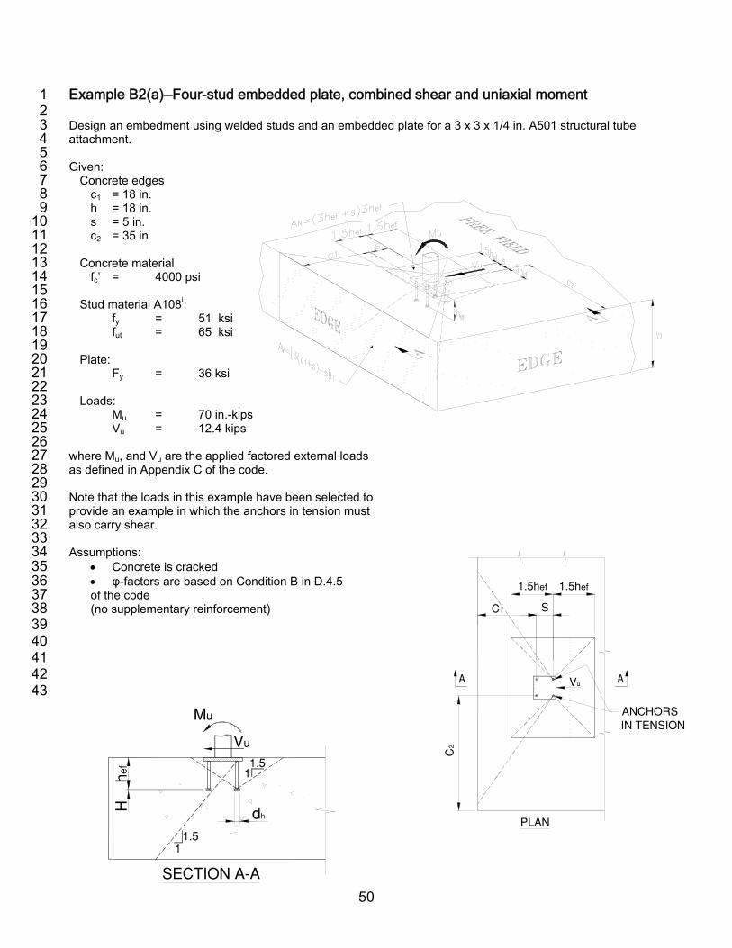
50
Example B2(a)—Four-stud embedded plate, combined shear and uniaxial moment 1 2 Design an embedment using welded studs and an embedded plate for a 3 x 3 x 1/4 in. A501 structural tube 3 attachment. 4 5 Given: 6
Concrete edges 7 c1 = 18 in. 8 h = 18 in. 9 s = 5 in. 10 c2 = 35 in. 11 12
Concrete material 13 fc’ = 4000 psi 14 15
Stud material A108i: 16 fy = 51 ksi 17 fut = 65 ksi 18 19
Plate: 20 Fy = 36 ksi 21 22
Loads: 23 Mu = 70 in.-kips 24 Vu = 12.4 kips 25 26 where Mu, and Vu are the applied factored external loads 27 as defined in Appendix C of the code. 28 29 Note that the loads in this example have been selected to 30 provide an example in which the anchors in tension must 31 also carry shear. 32 33 Assumptions: 34
• Concrete is cracked 35 • φ-factors are based on Condition B in D.4.5 36 of the code 37 (no supplementary reinforcement) 38
39 40 41 42 43
C1
PLAN
S
1.5hef
C2
1.5hef
Vu
ANCHORS IN TENSION
hef
H dh
Mu
1.51
Vu
SECTION A−A
1.51

51
CODE SECTION DESIGN PROCEDURE CALCULATION
1. STEP 1: Determine required steel area of the studs 2. 3. 4. 5. 6. 7. 8. 9. 10. 11. 12. 13. 14. 15. 16. 17. 18. 19. 20. 21. 22. 23. 24. 25. 26. AISC 27. Chapter F 28. 29. 30. 32. 33. 34. 35. 36. 37. 38. 39. 40. 41. D.4.1.1 42. 43. D.5.1.2 44. 45. D.4.5 46. 47. 48. 49. 50. 51. 52. 53. 54.
BASE PLATE Determine the plate size and thickness and anchor bolt size for moment Assume a 1/2 in. thick, 7 x 7 in. plate. Stud spacing, s = 5 in., is given. Assume the center of compression force resultant is at a distance dc = 2t away from the outer edge of the supported member, the structural tube. The center of the tension force is at the center of the anchors in tension. Determine the lever arm d between the center of compression and tension forces.
Calculate the tension in the anchors.
Design the plate using the AISC LRFD Code.ii Use the plastic moment Mp to define the nominal strength of the plate in bending, and use φb = 0.9 in accordance with the AISC Code. Assume that the full width of the base plate is effective. Strength of steel plate is greater than the applied ultimate moment, but close to the limit. Use 5/8 in. plate. ANCHORS Tension: Determine the required stud area Aset for tension. Assume ductile design and use the corresponding φ factor in accordance with D.4.5. φ = 0.8 for tension load From Appendix A, Table 2:
Anchor
diameter, in.
Effective area (gross area for stud) in.2
3/8 0.110 1/2 0.196 5/8 0.307
d = dt + ds + dc
=1.0 + 3.0 + 1.0 = 5.0
T = Mu/d = 70/5.0 = 14.0 kips Mupl = Tdt = 14.0 * 1.0 = 14.0 in.-k Mn = Mp = FyZ φbMp = 0.9FyZ Z = 1/4 (7)(0.5)2 = 0.44 in.3 φbMp = 0.9(36)(0.44) = 14.3 > Mupl =14 k-in. OK Use plate, 7 x 7 x 5/8 in. thick plate T = Nu = φNs = φnAsetfut φ = 0.80 n = 2 anchors fut = 65 ksi Aset,req = Nu/φnfut
T
Mu
C
Vu
d
dc=2t dt
t
ds
21

52
CODE SECTION DESIGN PROCEDURE CALCULATION 1. 2. 3. 4. 5. 6. 7.
= 14.0/(0.8 * 2 * 65) Aset,req = 0.135 in.2 Use 4-1/2 in. diameter studs. Ase = Aset,prov = 0.196 in.2 OK
8. 9. 10. 11. 12. 13. 14. 15. 16. 17. 18. 19. 20. 21. 22. 23. 24. 25. 26. 27. 28. 29. 30. 31. 32. 33. 34. 35. 36. 37. 38. 39. 40. 41. 42. 43. 44. 45.
46.
47. D.6.1 48. 49. 50. 51. 52. 53.
Shear: Shear forces in anchors: From the figure on the right the forces in each anchor group and force due to friction can be calculated. From above, C and T are already calculated Determine friction force Vf1
Shear strength Because this is an embedded base plate, shear strength may be calculated using either direct shear or shear friction; however, only the direct shear option will be shown herein.iii. Using the steel area Ase determined from tension above, calculate the available shear strength of the anchors.
Shear strength using direct shear and friction from compression
A. Assume all four anchors resist shear (Concrete breakout strength needs to be checked; see Step 3) Strength of front and back anchors, Vs1 and Vs2:
Total strength of front and back anchors:
Strength-reduction factor:
Design strength of anchors at Line 1, φVs1 and Line 2, φVs2 (Note: strength is based on fut, not
C = T = 14.0 kips Vf1 = 0.4C = 0.4 * 14 = 5.6 kips Asev = Asev1 + Asev2
Asev1 = Asev2
Asev1 = nAse= 2 * 0.196 = 0.392 in.2
Vs1 = Vs2 = nAse1fut (D-18) = 2 * 0.196 * 65 = 25.5 kips Vs = 2 * 25.5 = 51.0 kips
Vs2
C
21
Vs1
T
Vu
Mu
d
Vf1
=0.4C
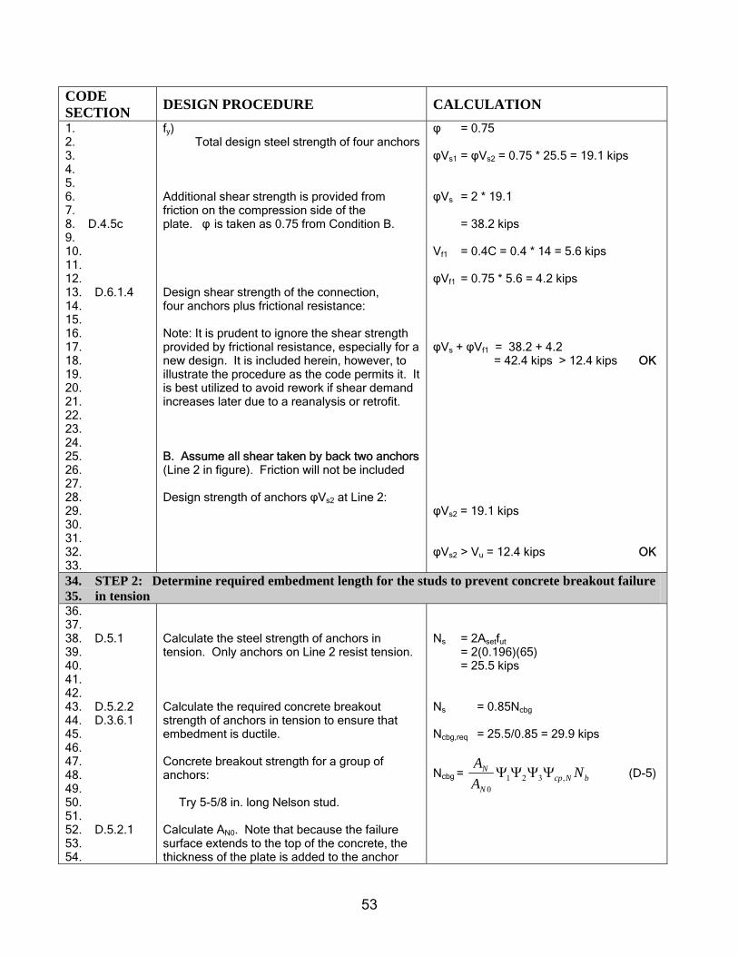
53
CODE SECTION DESIGN PROCEDURE CALCULATION 1. 2. 3. 4. 5. 6. 7. 8. D.4.5c 9. 10. 11. 12. 13. D.6.1.4 14. 15. 16. 17. 18. 19. 20. 21. 22. 23. 24. 25. 26. 27. 28. 29. 30. 31. 32. 33.
fy) Total design steel strength of four anchors
Additional shear strength is provided from friction on the compression side of the plate. φ is taken as 0.75 from Condition B.
Design shear strength of the connection, four anchors plus frictional resistance: Note: It is prudent to ignore the shear strength provided by frictional resistance, especially for a new design. It is included herein, however, to illustrate the procedure as the code permits it. It is best utilized to avoid rework if shear demand increases later due to a reanalysis or retrofit. B. Assume all shear taken by back two anchors (Line 2 in figure). Friction will not be included Design strength of anchors φVs2 at Line 2:
φ = 0.75 φVs1 = φVs2 = 0.75 * 25.5 = 19.1 kips φVs = 2 * 19.1 = 38.2 kips Vf1 = 0.4C = 0.4 * 14 = 5.6 kips φVf1 = 0.75 * 5.6 = 4.2 kips φVs + φVf1 = 38.2 + 4.2 = 42.4 kips > 12.4 kips OK φVs2 = 19.1 kips φVs2 > Vu = 12.4 kips OK
34. STEP 2: Determine required embedment length for the studs to prevent concrete breakout failure 35. in tension 36. 37. 38. D.5.1 39. 40. 41. 42. 43. D.5.2.2 44. D.3.6.1 45. 46. 47. 48. 49. 50. 51. 52. D.5.2.1 53. 54.
Calculate the steel strength of anchors in tension. Only anchors on Line 2 resist tension. Calculate the required concrete breakout strength of anchors in tension to ensure that embedment is ductile. Concrete breakout strength for a group of anchors: Try 5-5/8 in. long Nelson stud. Calculate AN0. Note that because the failure surface extends to the top of the concrete, the thickness of the plate is added to the anchor
Ns = 2Asetfut = 2(0.196)(65) = 25.5 kips Ns = 0.85Ncbg
Ncbg,req = 25.5/0.85 = 29.9 kips
Ncbg = bNcpN
N NAA
,3210
ΨΨΨΨ (D-5)

54
CODE SECTION DESIGN PROCEDURE CALCULATION 1. 2. 3. 4. 5. 6. 7. 8. 9. 10. 11. 12. 13. 14. 15. 16. 17. D.5.2.4 18. 19. D.5.2.5 20. 21. D.5.2.6 22. 23. D.5.2.7 24. 25. 26. D.5.2.2 27. 28. 29. 30. 31. 32. D.5.2.1 33. 34. 35. 36. 37. 38. 39. 40. 41. 42. 43.
length.
hef = 5.625 + tplate – burn off (See Table 6) = 5.625 + 0.625 - 0.125 = 6.125 in. Calculate AN. There are no edge effects, because 1.5 * 6.125 = 9.2 in. < c1 = 23 in. Modification factors are all 1.0 for: Eccentricity effects Ψ1
Edge effects Ψ2 Concrete cracking Ψ3 Concrete corner splitting Ψcp,N
Basic concrete breakout strength Nb of a single anchor in tension in cracked concrete: k = 24 for cast-in anchors Concrete breakout strength for group Embedment is ductile in tension. Strength controlled by steel. This satisfies the shear friction requirement from Step 1.
AN0 = 9(hef)
2 (D-6) = 9 * (6.125)2
= 337.6 in.2 AN = (2 * 1.5 * 6.125 + 5)(2 * 1.5 * 6.125) = 429.5 in.2 AN/AN0 = 429.5/337.6 = 1.3 Ψ1 = 1.0 (D-9) Ψ2 = 1.0 (D-10) Ψ3 = 1.0 Ψcp,N = N/A (not post-installed) (D-12) Nb = (D-7) = 24 (4000)0.5hef
1.5
= 1.52(6.125)1.5
= 23.0 kips
Ncbg = bNcpN
N NAA
,3210
ΨΨΨΨ
= 1.3 (1.0)(1.0)(1.0)23.0 = 29.9 kips ≥ Ncbg,req = 29.9 kips OK Use 4-1/2 in. diameter x 5-5/8 in. long anchors at 5 in. spacing
44. STEP 3 : Check pullout strength of anchor 45. 46. D.5.3 47. 48. D.5.3.4 49. 50. 51. 52. 53. D.5.3.5 54.
Calculate the pullout strength of the anchor in tension in accordance with D.5.3. Design embedment as ductile in accordance with D.3.6.1. Concrete is cracked per problem statement. Ψ4 = 1.0
Npn = Ψ4Np (D-14) Np = Abrg8fc’ (D-15) = 8 * 4 Abrg = 32 Abrg
5.1'efc hfk

55
CODE SECTION DESIGN PROCEDURE CALCULATION 1. 2. 3. 4. 5. 6. 7. 8. 9. D.3.6.1 10. 11. 12. 13. 14. 15. 16. 17. 18. 19. 20. 21. 22. 23. 24.
Calculate the bearing area. From manufacturer data, anchor head diameter is 1.0 in. for a 1/2 in. diameter stud (See Table 6 in Appendix A). Pullout strength to maintain ductile design in accordance with D.3.6.1.
Ψ4 = 1.0 Abrg = π * (1.02 - 0.52)/4 = 0.59 in.2 Npn = 1 * 3 2* 0.59 = 18.9 kips 0.85Npn = 0.85 * 18.9 = 16.1 kips each anchor = 32.2 kips for two anchors
Ns = 25.5 kips
Ductile 1/2 in. diameter studs are OK for pullout
25. STEP 4 : Check concrete side-face blowout 26. 27. D.5.4 28. 29. 30. 31. 32. 33.
Check anchors closest to the edge for side-face blowout.
c1 > 0.4hef 18 in. > 0.4 * 6.125 = 2.45 in. Side-face blowout Nsb need not be checked.

56
1
1. STEP 5 : Check concrete breakout failure in shear 2. 3. To determine the critical concrete breakout strength, three modes of failure would be considered. They are shown 4. below. The first mode places the failure cone at the front anchors, and a strength check is made against 1/2 of the 5. applied shear Vu. The second mode considers the failure cone initiating at the back anchors, and a strength check is 6. made against the total shear Vu. The final mode is a conservative check, which assumes that all of the shear is acting at 7. the front anchors. This check might be considered if significantly oversized holes are used as in a column base plate. 8. Per the note on Fig. RD.6.2.1(b) of the Commentary, the only check that is required for this problem is Mode 2, 9. because the studs are welded to the anchor plate. 10. 11. 12. 13. 14. 15. 16. 17. Mode 1 18. 19. 20. 21. 22. 23. 24. 25. 26. Strength 27. c1 ϕVcbg1 ϕVs1 Vu 28. 29. 23 in. 25.1 kips19.1 kips* 8.2 kips** 30. 31. 32. Mode 2 Ductility 33. (Only check c1 0.85Vcbg2 Vs2 Vu 34. required for 23 in. 28.5 kips 25.5 kips 8.2 kips**
35. welded studs) 36. * from page 3 37. ** Shear to be resisted = 12.4 – 4.2 = 8.2 kips, page 3 38. 39. 40. 41. 42. 43. 44. 45.
46. 47. 48. Mode 3 49. 50. 51. 52. 53.
SECTION A−A
Mu
Vu
1 2
Vu
SECTION A−A
Mu
Vu
1 2
Vu/2 Vu/2
PLAN
Vu
Vu/4
Vu/4 Vu/4
Vu/4
21
PLAN
Vu
Vu/2
Vu/2
21
SECTION A−A
Mu
Vu
1 2
Vu
PLAN
Vu
21
Vu/2
Vu/2

57
1 1. 2. 3. 4. 5. D.6.2.1 6. 7. 8. 9. 10. 11. 12. 13. 14. 15. 16. 17. D.6.2.5 18. D.6.2.6 19. D.6.2.7 20. 21. D.6.2.3 22. 23. 24. 25. 26. 27. 28. 29. 30. 31. 32. D.3.6.1 33. 34. 35. 36. 37. 38. D.4.5 39. 40. 41. D.6.2.1 42. 43. 44. 45. 46. 47. 48. 49.
Determine concrete breakout strength using Mode 2. For a plate with welded studs Mode 2 can be used to calculate the concrete breakout strength. Therefore c1=18 + 5 = 23 in. The failure cone passes through the bottom of the slab, so the Av equation uses the full slab thickness (h = 18 in. < 23 in.). Modification factors: Eccentricity on Anchor group Ψ5
Second edge effect Ψ6 Assumed cracked Ψ7 Note: by definition, l is limited to 8do= 4 in. Nominal concrete breakout strength: Check ductility, two anchors on Line 2: Check for strength: Strength-reduction factor: Design group concrete breakout strength:
bvo
vcbg V
AA
V 765 ΨΨΨ=
(D-21) Av = (3c1+s)(h) = (3 * 23 + 5)(18)=1332 in.2 Avo= 4.5 c1
2=4.5 * 232=2381 in.2 (D-22) Av/Avo = 0.56 Ψ5 = 1.0 No eccentricity Ψ6 = 1.0 c2 > 1.5c1 (D-26) Ψ7 = 1.0 (D-24) = 59.8 kips Vcbg2 = 0.56*1.0*1.0*1.0*59.8 = 33.5 kips 0.85Vcbg2 = 0.85 * 33.5 = 28.5 > Vs2 = 25.5 kips Mode 2 is ductile ϕ = 0.75 ϕVcbg = 0.75 * 33.5 = 25.1 > Vu = 8.2 kips OK for strength
50. STEP 6 : Check group pryout 51. 52. D.6.3 53. 54. 55. 56.
Concrete pryout of the anchors in shear must be checked Two anchors :
Vcpg= kcp * Ncbg (D-29) kcp = 2 for hef > 2.5 in. Ncbg= 29.9 kips
5.11
2.0
)('8 cfdd
V coo
b ⎟⎟⎠
⎞⎜⎜⎝
⎛=
l
5.12.0
)23(40005.05.0
48 ⎟⎠⎞
⎜⎝⎛=

58
1. 2. 3. 4. 5. 6.
Vcpg= 2 * 29.9 = 59.8 kips 0.85 * Vcpg = 0.85 * 59.8 = 50.8 > 25.5 kips Ductile
7. STEP 7 : Summary 8. 9. 10. 11. 12. 13. 14. 15. 16. 17. 18. Step 1 19. Step 1/ D.4.5.a 21. Step 3/D.4.5.c 23. Step 5/ D.4.5.c 25. Step 6/ D.4.5.c 27. 28. D.4.1.2 29. 30. 31. 32. 33. Step 1 34. Step 1/D.4.5.a 36. Step 3/D.4.5.c 38. Step 7/D.4.5.c 40. 41. D.4.1.2 42. 43. 44. 45.
Stud: Diameter d0 = 1/2 in. Length L = 5-5/8 in. Effective depth hef = 6.13 in. Base plate thickness, t = 5/8 in. Anchors are ductile TENSION Applied load Steel strength Concrete breakout strength Concrete pullout strength Concrete side face-blowout strength Design strength of stud, tension SHEAR: Mode 2 (frictional resistance counted) Applied load, 12.4 – 4.2 = 8.2 kips, page 6, Steel strength Concrete breakout strength (nonductile) Concrete pryout strength Design strength of stud, shear
Nu = 14.0 kips Step 1 φNs = 0.80 * 25.5 = 20.4 kips φNcbg = 0.75 * 29.9 = 22.4 kips φNpn =0.75 * 2 * 18.9 = 28.4 kips c1 > 0.4hef so this is not applicable φNn = min (φNs, φNcbg, φNpn )
= min (20.4, 22.4, 28.4) = 20.4 kips > Nu = 14.0 kips OK Vu = 8.2 kips φVs = 0.75 * 25.5 = 19.1 kips φVcb g= 0.75 * 33.5 = 25.1 kips φVcpg= 0.75 * 59.8 = 44.9 kips φVn = min (φVs, φVcbg, φVcpg) = min (19.1, 25.1, 44.9) = 19.1 kips > Vu = 8.2 kips OK
46. STEP 8 : Check for tension-shear interaction 47. 48. 49. D.7.3 50. 51. 52. 53. 54.
Anchors subject to combined shear and tension forces must meet the tension-shear interaction requirements of D.7 Mode 2:
(D-30)
2.1≤+n
u
n
u
VV
NN
φφ
1/2"
5/8"
6 1/
8"5 5/
8"−1
/8"
burn
off
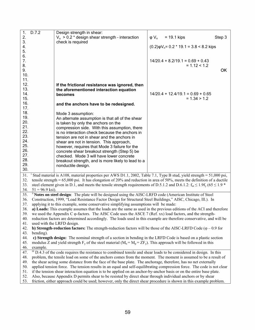
59
1. D.7.2 2. 3. 4. 5. 6. 7. 8. 9. 10. 11. 12. 13. 14. 15. 16. 17. 18. 19. 20. 21. 22. 23. 24. 25. 26. 27. 28. 29. 30.
Design strength in shear: Vu > 0.2 * design shear strength – interaction check is required If the frictional resistance was ignored, then the aforementioned interaction equation becomes and the anchors have to be redesigned. Mode 3 assumption: An alternate assumption is that all of the shear is taken by only the anchors on the compression side. With this assumption, there is no interaction check because the anchors in tension are not in shear and the anchors in shear are not in tension. This approach, however, requires that Mode 3 failure for the concrete shear breakout strength (Step 5) be checked. Mode 3 will have lower concrete breakout strength, and is more likely to lead to a nonductile design.
φ Vn = 19.1 kips Step 3 (0.2)φVn= 0.2 * 19.1 = 3.8 < 8.2 kips 14/20.4 + 8.2/19.1 = 0.69 + 0.43 = 1.12 < 1.2 OK 14/20.4 + 12.4/19.1 = 0.69 + 0.65 = 1.34 > 1.2
31. i Stud material is A108, material properties per AWS D1.1, 2002, Table 7.1, Type B stud, yield strength = 51,000 psi, 32. tensile strength = 65,000 psi. It has elongation of 20% and reduction in area of 50%, meets the definition of a ductile 33. steel element given in D.1, and meets the tensile strength requirements of D.5.1.2 and D.6.1.2: fut ≤ 1.9fy (65 ≤ 1.9 * 34. 51 = 96.9 ksi). 35. ii Notes on steel design: The plate will be designed using the AISC-LRFD code (American Institute of Steel 36. Construction, 1999, “Load Resistance Factor Design for Structural Steel Buildings,” AISC, Chicago, Ill.). In 37. applying it to this example, some conservative simplifying assumptions will be made: 38. a) Loads: This example assumes that the loads are the same as used in the previous editions of the ACI and therefore 39. we used the Appendix C φ-factors. The AISC Code uses the ASCE 7 (Ref. xx) load factors, and the strength- 40. reduction factors are determined accordingly. The loads used in this example are therefore conservative, and will be 41. used with the LRFD design. 42. b) Strength-reduction factors: The strength-reduction factors will be those of the AISC-LRFD Code (φ – 0.9 for 43. bending). 44. c) Strength design: The nominal strength of a section in bending in the LRFD Code is based on a plastic section 45. modulus Z and yield strength Fy of the steel material (Mn = Mp = ZFy). This approach will be followed in this 46. example. 47. iii D.4.3 of the code requires the resistance to combined tensile and shear loads to be considered in design. In this 48. problem, the tensile load on some of the anchors comes from the moment. The moment is assumed to be a result of 49. the shear acting some distance from the face of the base plate. The anchorage, therefore, has no net externally 50. applied tension force. The tension results in an equal and self-equilibrating compression force. The code is not clear 51. if the tension shear interaction equation is to be applied on an anchor-by-anchor basis or on the entire base plate. 52. Also, because Appendix D permits shear to be resisted by direct shear through individual anchors or by shear 53. friction, either approach could be used; however, only the direct shear procedure is shown in this example problem.

60
Example B2(b)—Four-anchor surface-mounted plate, combined shear and uniaxial moment 1 2 3 Design an embedment using cast-in-place anchors and a flexible surface-mounted plate for a 3 x 3 x 1/4 in. 4 A501 structural tube attachment. 5 6 Given: 7
Concrete edges 8 c1 = 18 in. 9 h = 18 in. 10 s = 5 in. 11 c2 = 35 in. 12 13
Concrete material 14 fc’ = 4000 psi 15 16
Rod material F1554 Gr.105i: 17 fy = 105 ksi 18 fut = 120 ksi 19 20
Plate 21 Fy = 36 ksi 22 23
Loads 24 Mu = 70 in.-kips 25 Vu = 12.4 kips 26 27 Where Mu, and Vu are the applied factored external loads 28 using load factors as defined in Appendix C of the code. 29 30 See introduction for commentary on the distribution of 31 stresses to the anchors for this problem. 32 33 34 Assumptions: 35
• Concrete is cracked 36 • φ-factors are based on Condition B in D.4.5 of the code 37
(no supplementary reinforcement) 38 39 40
41 42 43
C1
PLAN
S
1.5hef
C2
1.5hef
Vu
1 2
ANCHORS IN TENSION
Vu
11.5
SECTION A−A
hef
Mu
11.5 dh
H
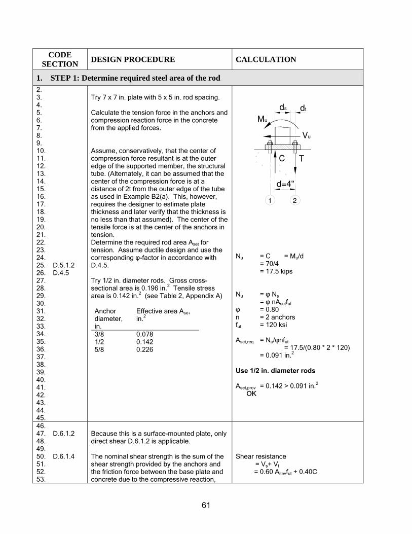
61
CODE SECTION DESIGN PROCEDURE CALCULATION
1. STEP 1: Determine required steel area of the rod 2. 3. 4. 5. 6. 7. 8. 9. 10. 11. 12. 13. 14. 15. 16. 17. 18. 19. 20. 21. 22. 23. 24. 25. D.5.1.2 26. D.4.5 27. 28. 29. 30. 31. 32. 33. 34. 35. 36. 37. 38. 39. 40. 41. 42. 43. 44. 45.
Try 7 x 7 in. plate with 5 x 5 in. rod spacing. Calculate the tension force in the anchors and compression reaction force in the concrete from the applied forces. Assume, conservatively, that the center of compression force resultant is at the outer edge of the supported member, the structural tube. (Alternately, it can be assumed that the center of the compression force is at a distance of 2t from the outer edge of the tube as used in Example B2(a). This, however, requires the designer to estimate plate thickness and later verify that the thickness is no less than that assumed). The center of the tensile force is at the center of the anchors in tension. Determine the required rod area Aset for tension. Assume ductile design and use the corresponding φ-factor in accordance with D.4.5. Try 1/2 in. diameter rods. Gross cross-sectional area is 0.196 in.2 Tensile stress area is 0.142 in.2 (see Table 2, Appendix A)
Anchor diameter, in.
Effective area Ase, in.2
3/8 0.078 1/2 0.142 5/8 0.226
T
Mu
C
Vu
d=4"
ds dt
21 Nu = C = Mu/d = 70/4 = 17.5 kips Nu = φ Ns = φ nAsetfut φ = 0.80 n = 2 anchors fut = 120 ksi Aset,req = Nu/φnfut = 17.5/(0.80 * 2 * 120) = 0.091 in.2 Use 1/2 in. diameter rods Aset,prov = 0.142 > 0.091 in.2 OK
46. 47. D.6.1.2 48. 49. 50. D.6.1.4 51. 52. 53.
Because this is a surface-mounted plate, only direct shear D.6.1.2 is applicable. The nominal shear strength is the sum of the shear strength provided by the anchors and the friction force between the base plate and concrete due to the compressive reaction,
Shear resistance = Vs+ Vf = 0.60 Asevfut + 0.40C
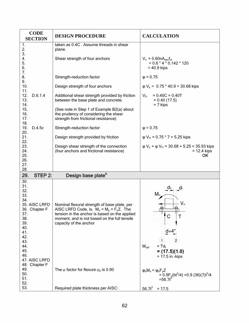
62
CODE SECTION DESIGN PROCEDURE CALCULATION
1. 2. 3. 4. 5. 6. 7. 8. 9. 10. 11. 12. D.6.1.4 13. 14. 15. 16. 17. 18. 19. D.4.5c 20. 21. 22. 23. 24. 25. 26. 27. 28.
taken as 0.4C . Assume threads in shear plane. Shear strength of four anchors Strength-reduction factor Design strength of four anchors Additional shear strength provided by friction between the base plate and concrete. (See note in Step 1 of Example B2(a) about the prudency of considering the shear strength from frictional resistance) Strength-reduction factor Design strength provided by friction Design shear strength of the connection (four anchors and frictional resistance)
Vs = 0.60nAsevfut = 0.6 * 4 * 0.142 * 120 = 40.9 kips φ = 0.75 φ Vs = 0.75 * 40.9 = 30.68 kips Vf1 = 0.40C = 0.40T = 0.40 (17.5) = 7 kips φ = 0.75 φ Vf1 = 0.75 * 7 = 5.25 kips φ Vs + φ Vf1 = 30.68 + 5.25 = 35.93 kips > 12.4 kips OK
29. STEP 2: Design base plateii 30. 31. 32. 33. 34. 35. AISC LRFD 36. Chapter F 37. 38. 39. 40. 41. 42. 43. 44. 45. 46. 47. AISC LRFD 48. Chapter F 49. 50. 51. 52. 53.
Nominal flexural strength of base plate, per AISC LRFD Code, is, Mn = Mp = FyZ. The tension in the anchor is based on the applied moment, and is not based on the full tensile capacity of the anchor The ϕ factor for flexure ϕb is 0.90 Required plate thickness per AISC:
T
Mu
C
Vu
d=4"
ds dt
21 Mupl = Tdt = (17.5)(1.0) = 17.5 in.-kips φbMn = φbFyZ = 0.9Fy(bt2/4) =0.9 (36)(7)t2/4 =56.7t2 56.7t2 = 17.5

63
CODE SECTION DESIGN PROCEDURE CALCULATION
1. 2. 3. 4.
t = 0.55 in. Use 7” X7” X 5/8” plate
5. STEP 3: Determine required embedment length for the studs to prevent concrete 6. breakout failure 7. 8. D.5.1 9. 10. 11. 12. 13. D.3.6.1 14. 15. 16. 17. D.5.2 18. D.3.6.1 19. 20. 21. 22. 23. 24. 25. 26. 27. 28. 29. 30. 31. D.5.2.4 32. D.5.2.5 33. D.5.2.6 34. D.5.2.7 35. 36. 37. D.5.2.2 38. 39. 40. 41. 42. 43. 44. 45. 46. 47. 48. 49. 50. 51. 52. 53.
Calculate design tension on anchors assuming two studs resist tensile loads. Calculate the concrete breakout strength of anchors in tension so that embedment is ductile. Concrete breakout strength for a group of anchors Try 1/2 in. diameter headed rod with 8-1/2 in. effective length hef. Modification factors are all 1.0 for: Eccentricity effects Ψ1 Edge effects Ψ2 Concrete cracking Ψ3 Without splitting reinforcement Ψcp,N Basic concrete breakout strength Nb of a single anchor in tension in cracked concrete. k = 24 for cast-in anchors Concrete breakout strength for group.
Ns = nAsetfut (D-3)
= 2 * 0.142 * 120 = 34.1 kips Ns = 0.85Ncbg Ncbg, req= 34.1/0.85 = 42.6 kips
Ncbg= bNcpN
N NAA
,3210
ΨΨΨΨ (D-5)
AN0 = 9(hef)
2 (D-6) = 9 * 8.52
= 650 in.2 AN = (2 * 1.5 * 8.5 + 5)(2 * 1.5 * 8.5) = 778 in.2 AN/AN0 = 778/650 = 1.20 Ψ1 = 1.0 Ψ2 = 1.0 Ψ3 = 1.0 Ψcp,N = N/A
Nb = 5.1'efc hfk
(D-8) = 24 (4000)0.5(hef)
1.5 = 1518(hef)
1.5 lbs = 1.52 * 8.51.5 kips = 37.6 kips

64
CODE SECTION DESIGN PROCEDURE CALCULATION
1. 2. 3. 4. 5. 6. 7. 8. 9. 10. 11. 12. 13. 14.
Ncbg = bN
N NAA
3210
ΨΨΨ
Ncbg = 1.20 * 1.0 * 1.0 * 1.0 * 37.6 = 45.1 > 42.6 kips OK Therefore, embedment is ductile Strength controlled by steel Use 4 -1/2 in. diameter anchors with 8-1/2 in. embedment depth at 5 in. spacing
15. STEP 4: Check pullout strength of anchor 16. 17. D.5.3 18. 19. 20. 21. 22. D.5.3.5 23. 24. 25. 26. 27. 28. 29. 30. 31. 32. 33. 34. 35. 36. 37. 38. 39. 40. 41. 42. 43. 44. 45. 46. 47. 48. 49. 50. 51. 52. 53.
Calculate the pullout strength of the anchor in tension in accordance with D.5.3. Design embedment as ductile in accordance with B.3.6.1. Concrete is cracked per problem statement. Ψ4 = 1.0 Calculate the bearing area. Assume heavy hex head for the rod. Appendix A, for 1/2 in. diameter rod, F = 7/8 in., C = 1.0 in. Ahead = (3F2/2)tan30º Ahead = (3 * 0.8752/2)(0.577) = 0.663 in.2 Arod = π * 0.52 /4 = 0.196 in.2 Pullout capacity for two anchors Determine required bearing area Try a hardened washer, with diameter D. (Table 5 SAE hardened washer)
Npn = Ψ4Np (D-14) Np = Abrg8fc’ (D-15) = 8 * 4 * Abrg = 32 Abrg Ψ4 = 1.0 Abrg = Ahead – Arod = 0.663 - 0.196 = 0.47 in.2 -see also Table 4(c) Npn = 1 * 32 * 0.47 = 15.0 kips each anchor 0.85Npn = 0.85 * 2 * 15.0 =25.5 < Ns =34.1 kips, No Good Abrg req = 34.1/(2 *32 * 0.85) =0.625 in.2 each anchor D2 = 4 * (0.625)/ π D = 0.89 in. each anchor Use a 1/2 in. washer with OD 1.167 in. Ahead = π * 1.1672 /4 = 1.07 in.2 Abrg = Ahead – Arod = 1.07 – 0.196

65
CODE SECTION DESIGN PROCEDURE CALCULATION
1. 2. 3. 4. 5. 6. 7. 8. 9. 10. 11. 12. 13. 14. 15. 16. 17.
= 0.874 > 0.625 in.2 Check: Npn = 1 * 32 * 0.874 = 27.9 kips each anchor = 55.9 kips for 2 anchors 0.85Npn = 0.85 * 55.9 = 47.5 >Ns = 34.1 kips Ductile, OK Use 1/2 in. diameter rods with 1.167 in. OD SAE hardened washer on head.
18. STEP 5: Check concrete side-face blowout 19. 20. 21. D.5.4 22. 23. 24.
Check anchors closest to the edge for side-face blowout.
c1 > 0.4hef D.5.4.1 18 in. > 0.4(6.125) = 2.45 in. Side-face blowout Nsb need not be checked.
25. STEP 6: Check concrete shear breakout

66
CODE SECTION DESIGN PROCEDURE CALCULATION
1. To determine the critical concrete breakout strength, three modes of failure should be considered. 2. They are shown below. The first mode places the failure cone at the front anchors, and a strength check 3. is made against 1/2 of the applied shear Vu. The second mode considers the failure cone initiating at 4. the back anchors, and a strength check is made against the total shear Vu. The final mode is a 5. conservative check, which assumes that all of the shear is acting at the front anchors. This check might 6. be considered if significantly oversized holes are used as in a column base plate. 7. 8. 9. 10. Concrete Steel Applied 11. breakout strength load
12. c1 0.85Vcbg1 Vs1 ϕVs1 Vu1 Vu2 13. in. k k k k k 14. Mode 1 18 22.4 20.5 15.4 3.6* 3.6*
15. 16. DUCTILE – OK for strength, see pages 6 & 7 17. 18. 19. * Shear to be resisted = 12.4 – 5.25 = 7.15 kips 20. Each row resists, 0.5 * 7.15 = 3.6 kips 21. 22. 23. 24. Concrete Steel Applied 25. breakout strength load
26. c1 0.85ϕVcbg2 Vs2 ϕVs2 Vu1 Vu2 27. in. k k k k k 28. Mode 2 23 24.9 20.5 15.4 3.6* 3.6*
29. 30. DUCTILE – OK for strength, see pages 7 & 8 31.
32.. 33. * see note above 34. 35. 36. 37. 38. 39. Concrete Steel Applied 40. breakout strength load
41. c1 0.85Vcbg1 Vs1 ϕVs2 Vu1 Vu2 42. in. k k k k k 43. Mode 3 18 22.4 20.5 15.4 7.2 0
44. 45. DUCTILE – OK for Strength 46. 47. 48. 49. D.6.2 50. 51. 52. 53. 54. 55.
Mode 1: Because the plate is not rigidly connected to the anchor, check the anchors nearest to the edge using 1/2 the applied shear.
bvo
vcbg V
AA
V 765 ΨΨΨ=
(D-21)
Mu
SECTION A−A
Vu
Vu/2
21
Vu/2
PLAN
VuVu/4Vu/4 Vu/4
Vu/4
1 2
PLAN
Vu
21
Vu/2
Vu/2
Mu
SECTION A−A
Vu
21
Vu
PLAN
Vu
21
Vu/2Vu/2
Mu
SECTION A−A
Vu
21
Vu

67
CODE SECTION DESIGN PROCEDURE CALCULATION
1. 2. 3. 4. 5. 6. 7. D.6.2.5 8. D.6.2.6 9. D.6.2.7 10. 11. 12. 13. 14. 15. 16. 17. 18. 19. 20. 21. 22. 23. 24. 25. 26. 27. 28. 29. 30. 31. 32. 33. D.6.2 34. 35. 36. 37. 38. 39. 40. 41. 42. 43. 44. D.6.2.5 45. 46. D.6.2.6 47. 48. D.6.2.7 49. 50. 51. 52. 53. 54.
Therefore, c1=18. Note that the depth of Av is limited by h. Eccentricity on anchor group Ψ5
Second edge effect Ψ6 Second edge effect Ψ7 assumed cracked Note: by definition, l is limited to 8do= 4 in. Ductility check From Step 1 Vs = 40.9/2 = 20.5 kips (two anchors) strength Mode 2: Next, check against failure at the back anchors under the full shear. Therefore, c1 = 23. Note that the depth of Av is limited by h. Eccentricity on anchor group Ψ5
Second edge effect Ψ6
Second edge effect Ψ7 assumed cracked Note: by definition, l is limited to 8do = 4 in.
Av = (3c1+s)(h) = (3 * 18 + 5)(18) = 1062 in.2
Avo= 4.5 c1
2 = 4.5*182 = 1458 in.2 (D-22) Av/Avo=1062/1458=0.73 Ψ5= 1.0 No eccentricity Ψ6= 1.0 c2 > 1.5c1 (D-26) Ψ7=1.0
5.11
2.0
)('7 cfdd
V coo
b ⎟⎟⎠
⎞⎜⎜⎝
⎛=
l (D-23)
5.12.0
)18(40005.05.0
47 ⎟⎠⎞
⎜⎝⎛=bV
=bV 36.2 kips
)2.36)(0.1)(0.1)(0.1(73.0=cbgV
Vcbg = 26.4 kips 0.85 Vcbg =0.85(26.4) =22.4 > Vs =20.5 kips Ductile, OK φ Vs = 0.75 * 20.5 = 15.40 kips
bvo
vcbg V
AA
V 765 ΨΨΨ= (D-21)
Av = (3c1+s)(h) = (3 * 23 + 5)(18) = 1332 in.2
Avo= 4.5 c1
2 = 4.5*232 = 2381 in.2 (D-22) Av/ Avo=0.56 Ψ5= 1.0 No eccentricity

68
CODE SECTION DESIGN PROCEDURE CALCULATION
1. 2. 3. 4. 5. 6. 7. 8. 9. 10. 11. 12. 13. 14. 15. 16. 17. 18. 19. 20. 21. 22. 23. 24. 25. 26. 27. 28. 29. 30. 31. 32. 33. 34. 35. 36. 37. 38. 39. 40. 41. 42. 43. 44. 45. 46.
Ductility check From Step 1, Vs = 40.9/2 = 20.5 kips (two anchors) Strength Note to reader: See Problem B2(a) for discussion of the assumptions regarding the distribution of shear stresses in the steel anchors in a Mode 2 failure. Mode 3 assumption: An alternate assumption is that all of the shear is taken by only the anchors on the compression side. With this assumption, there is no interaction check because the anchors in tension are not in shear and the anchors in shear are not in tension. This approach, however, requires that Mode 3 failure for the concrete shear breakout strength (Step 3) be checked. Mode 3 will have lower concrete breakout strength and is more likely to lead to a nonductile design, although in this particular example, it is ductile.
Ψ6= 1.0 c2> 1.5c1 (D-26) Ψ7= 1.0
5.11
2.0
)('7 cfdd
V coo
b ⎟⎟⎠
⎞⎜⎜⎝
⎛=
l (D-23)
5.12.0
)23(40005.05.0
47 ⎟⎠⎞
⎜⎝⎛=bV
=bV 52.3 kips
)3.52)(0.1)(0.1)(0.1(56.0=cbgV
Vcbg = 29.2 kips φ Vcbg = 0.75 * 29.2 = 21.9 kips 0.85Vcbg =0.85(29.2) =24.9 > Vs = 20.5 kips Ductile, OK φ Vs = 0.75 * 20.5 = 15.40 kips
47. STEP 7: Check group pryout 48. 49. D.6.3 50. 51. 52. 53.
Concrete pryout of the anchors in shear must be checked: Mode 1 is checked herein, Mode 2 can be similarly checked. (Note: The code states that Ncbg is taken from
Vcpg = kcp * Ncbg (D-29) kcp = 2 for hef > 2.5 in. Ncbg = 45.1 kips

69
CODE SECTION DESIGN PROCEDURE CALCULATION
1. 2. 3. 4. 5. 6.
Eq. (D-5).) Vcpg = 2 * 45.1 = 90.2 kips φVcpg= 0.75 * 90.2 = 67.7 kips > 12.4 kips O.K
7. STEP 8: Summary 8. 9. 10. 11. 12. 13. 14. 15. 16. 17. 18. 19. 20. 21. 22. Step 1 23. Step 3/D.4.5.a 25. Step 3/D.4.5.c 27. Step 4/D.4.5.c 29. Step 5/D.4.5.c 31. 32. D.4.1.2 33. 34. 35. 36. 37. D.4.1.2 38. 39. 40. 41. Step 1/D.4.5.a 43. Step 6/D.4.5.c 45. Step 7/D.4.5.c 46. 47. 48. 49. 50. 51. 52. 53.
Rod diameter d0= 1/2 in. Plate thickness t = 5/8 in. Effective length h = 8-1/2 in. TENSION Applied load Steel strength Concrete breakout strength Concrete pullout strength Concrete side-face blowout strength Design strength of stud, tension SHEAR - Mode 2 (frictional resistance considered) Applied load Steel strength, two anchors Concrete breakout strength Concrete pryout strength Design strength of stud, shear
Nu = 17.5 kips (from applied moment) φNs = 0.80 * 34.1 = 27.3 kips φNcbg = 0.75 * 45.1 = 33.8 kips φNpn = 0 .75 * 55.9 = 41.9 kips c1 > 0.4hef so this is Not Applicable φNn = min(φNs, φNcbg, φNpn )
= min(27.3, 33.8, 41.9) = 27.3 kips > Nu = 17.5 kips OK Vu = 12.4 – 5.25 = 7.2 kips φVs = 0.75 * (20.5) = 15.40 kips φVcbg = 0.75 * 29.2 = 21.9 kips φVcpg =0 .75 * 90.2= 67.7 kips φVn = min (φVs, φVcbg, φVcpg) = min (15.4, 21.9, 67.7) = 15.4 kips > Vu = 7.2 kips
8 1/
2"1/2"
1.167"
5/8"

70
CODE SECTION DESIGN PROCEDURE CALCULATION
1. 2. 3. 4. 5.
OK
6. STEP 9 : Check for tension-shear interaction 7. 8. D.7.3 9. 10.
Tension–shear interaction, Mode 2
17.5/27.3 + 7.2/15.4 = 1.11 < 1.2 OK
11. iASTM F 1554-00 specification, Grade 105, Class 1A, rod material will be used. Rod identification is (AB105) 12. with a tensile strength in the range of 125 to 150 ksi, and minimum yield strength of 105 ksi for ¼ to 3 in. 13. diameters. Reductions in area requirements vary. For anchor diameters < 2 in., elongation in 2 in. is 15%, 14. reduction in area is 45%, and meets the definition of a ductile steel element given in D.1. Also, max fut = 1.4 fy. 15. According to D.6.1.2, fut shall be ≤ 1.9 fy or 125, 000 psi. See also Table 1 for other materials. 16. ii Notes on steel design: The plate will be designed using the AISC-LRFD code (American Institute of Steel 17. Construction, 1999, “Load and Resistance Factor Design for Structual Steel Buildings,” AISE, Chicago, Ill.). In 18. applying it to this example, some conservative simplifying assumptions will be made: 19. Loads: This example assumes that the load combinations are the same as used in the previous editions of the ACI 20. and therefore we used the Appendix C φ factors. The AISC-LRFD code uses the ASCE 7 load factors, and the 21. strength-reduction factors are determined accordingly. The loads used in this example are therefore conservative, 22. and will be used with the LRFD design. 23. Strength-reduction factors: The strength-reduction factors will be those of the AISC-LRFD code (φ – 0.9 for 24. bending). 25. Strength design: The nominal strength of a section in bending in the LRFD code is based on a plastic section 26. modulus Z and yield strength Fy of the steel material (Mn = Mp = ZFy). This approach will be used in this 27. example.
28. iii AISC recommends oversizing holes for base plates. The forthcoming AISC Design Guide will contain the 29. following table for recommended rod hole size. In cases like this, it is possible to have the anchors closest to the 30. edge make contact with the base plate before the back anchors contact. The resulting breakout cone shown in 31. Mode 3 would need to be evaluated.

71
CODE SECTION DESIGN PROCEDURE CALCULATION
Shear Holes(diameter)
Normal Holes(diameter)
1/2 5/8 1 1/16
5/8 13/16 1 3/16
3/4 15/16 1 5/16
7/8 1 1/16 1 9/16
1 1 1/4 1 13/16
1 1/4 1 9/16 2 1/16
1 1/2 1 13/16 2 5/16
1 3/4 2 1/16 2 3/4
≥ 2 db+5/16 db+1 1/4
Maximum Permitted Nominal Anchor Rod Hole Dimensionsa,b,
in.Anchor Rod Diameter, db
in.
a The upper tolerance on tabulated nominal dimensions shall not exceed 1/16-in.
b The slight conical hole that naturally results from punching operations with properly matched punches and dies is
acceptable.
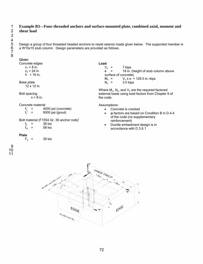
72
Example B3—Four-threaded anchors and surface-mounted plate, combined axial, moment and 1 shear load 2 3 4 Design a group of four threaded headed anchors to resist seismic loads given below. The supported member is 5 a W10x15 stub column. Design parameters are provided as follows. 6 7 8 Given: Concrete edges
c1 = 8 in. c2 > 24 in h = 16 in.
Base plate
12 x 12 in.
Bolt spacing s = 8 in. Concrete material
fc’ = 4000 psi (concrete) fc’ = 9000 psi (grout)
Bolt material (F1554 Gr. 36 anchor rods)i fy = 36 ksi fut = 58 ksi
Plate Fy = 36 ksi
Load
Vu = 7 kips e = 18 in. (height of stub column above surface of concrete) Mu = Vu x e = 126.0 in.-kips Nu = 3.0 kips
Where Mu, Nu, and Vu are the required factored external loads using load factors from Chapter 9 of the code. Assumptions:
• Concrete is cracked • φ-factors are based on Condition B in D.4.4
of the code (no supplementary reinforcement)
• Ductile embedment design is in accordance with D.3.6.1
9 10 11

73
SECTION A−A
Nu
h1
1.5
Hhe
f
Vu
1.511 2
c1
1 2 3 4 CODE SECTION DESIGN PROCEDURE CALCULATION
5. STEP 1: Design for moment and tension 1. 2. 3. 4. 5. 6. 7. 8. 9. 10. 11.
The plate size is 12 x 12 in., and the spacing s of the anchors is 8 x 8 in. Assume plate thickness t is 1 in. The first step is to calculate the tension force in the anchors and compression reaction force in the concrete from the applied forces. The base plate is just large enough in area to accommodate the column profile, that is, small
1.5h
ef
C2
S1.
5hef
1.5hef
PLAN
1.5hef
C1 S
1 2
SECTION A−A
h
1.51
1 2
NuVu
1 hef
1.5
H
c1
PLAN
S1.
5hef
1.5h
ef
1.5hef
S
1.5hef
C1
C2
1 2

74
CODE SECTION DESIGN PROCEDURE CALCULATION
1. AISC 2. 3. 4. 5. 6. 7. 8. 9. 10. 11. 12. 13. 14. 15. 16. 17. 18. 19. 20. 21. 22. 23. 24. 25. 26. 27. 28. 29. 30. 31. 32. 33. 34. 35. 36. 37. 38. 39. 40. 10.17.1 41. 9.3.2.5 42. 43. 44. 45. 46. 47. 48. 49. 50. 51. 52. 53. 54.
base plate (per AISC). For the shear toward the edge of the slab, the resultant tension from the moment is taken by the two left–hand side (Line 2) bolts, and the compression is taken in bearing on the effective bearing area. The bearing area is taken to the edge of the plate. The effective bearing area is taken as a distance t around the compression flange. This is an approximation. The error introduced into the calculation is negligible. The exact location of the compression resultant is difficult to determine. For design, take the resultant to act at the outside edge of the compression flange. This approximate analysis is deemed adequate. Determine the moment arm d. Determine the tension in the bolts and compression in the concrete. Check the effective bearing area based on the location of the resultant compression assumed previously. The bearing capacity is as given in the noted code section. An assumption has been made in this example that the grout under the plate, though unconfined, does not control because it is at least 9000 psi in compressive strength. Check the concrete instead. The ϕ-factors are as given in Chapter 9. ϕ is 0.65 for bearing. Due to confinement, use the maximum allowed factor, 2.
12"
12"
8"
CmNm
Nu Nu
8"
t
t
d
t
Effectivebearing area
de
12
.92
812.12
.0.12
1012
ind
inindind
ininind
e
e
=
−−−=
=−
=
kipsN
inkipsin
N
dM
N
m
m
um
14
9
126
=
−=
=
( )( )( )( )( )
253.13
1127.0296.3
2
85.02
inA
A
dtttbA
AfC
NC
bearing
bearing
effbearing
bearingcm
mm
=
+++=
+++=
′≤
=
φ
( )( )( )( )
OKkipskips
kipsC
inxC
AksixC
m
m
bearingm
8.5914
8.59
53.13485.065.02
485.065.022
≤
≤
≤
≤

75
CODE SECTION DESIGN PROCEDURE CALCULATION
1. 2. 3. 4. 5. 6. 7. 8. 9. 10. 11. 12. 13. 14. 15. 16. 17. 18. 19. 20. 21. 22. 23. 24. D.4.4 25. 26. 27. 28. 29. D.5.1.2 30. 31. 32. 33. 34. 35. 36. 37. 38. 39. 40. 41. 42. 43.
The effect of the tension force in shifting the location of the compression resultant is deemed negligible, and hence, it is conservative to algebraically add the bolt force distribution from moment to that from tension. Nu is the tension in the column, and Nub is the tension in the two bolts. Likewise, the compression on the bearing area can be reduced directly by the tension force even though the forces are centered at different locations. ϕ is 0.75 for tension strength in steel. Determine the required bolt area Aset req’d for tension. F1554 Gr. 36 is a ductile steel element. The ϕ-factors are as given in D.4.4. Note that Aset req’d is the effective tensile area required, and n is the number of bolts resisting the tension force. Note that the bolts resist shear as well, hence the margin in area of bolt provided (Aset). See Step 2 for consideration of shear. Net tensile area of threaded bolts can be found in Table 2 of Appendix A.
kipsN
kipskipsN
boltstwoinNNN
ub
ub
umub
5.152
314
)(2
=
+=
+=
kipsC
kipskipsC
areabearingonNCC um
5.122
314
)(2
=
−=
−=
sub NN φ≤
utsetub fAnN φ= (D-3)
( )2
'
'
'
18.0
58275.05.15
inA
A
fnNA
dreqset
dreqset
ut
ubdreqset
=
=
= φ
Use ¾ in. diameter threaded rods.
( )( )
( )( )( )boltstwokipsN
NfnAN
inA
inA
s
s
utsets
set
b
06.29582334.075.0
334.0
44.0
areaeffective
areanominal2
2
===
=
=
φφ
φφ (D-3)
kipskipsNN ubs
5.1506.29 >
>φ
OK
44. STEP 2: Design for shear 45. Concrete breakout modes (options) that will be used in design.

76
PLAN
Vu
21
Vu/2
Vu/2
PLAN
Vu
21
Vu/2
Vu/2
SECTION A−A
Vu
1
Vu
2
Nu
PLAN
Vu
21
Vu/2
Vu/2
SECTION A−A
Vu
1
Vu
2
Nu
CODE SECTION DESIGN PROCEDURE CALCULATION
a) Shear resisted by two anchors farthest
from edge b) Shear resisted by two anchors closest to edge SHEAR FORCE TOWARD EDGE

77
SECTION A−A
Vu
1
Vu
2
Nu
PLAN
Vu
21
Vu/2
Vu/2
SECTION A−A
Vu
1
Vu
2
Nu
CODE SECTION DESIGN PROCEDURE CALCULATION
c) Shear resisted by two anchors closest to edge d) Shear resisted by two anchors farthest from edge SHEAR FORCE AWAY FROM EDGE 1. D.6.1.2 2. D.6.1.3 3. D.4.4 4. 5. 6. 7. 8. 9. 10. 11. 12. 13. 14. 15. 16. 17. 18.
This is a base plate on grout therefore Section D.6.1 is applicable. Note that surface mounted plates with grout often come with oversized bolt holes.ii Therefore, in this example, it will be assumed that only two anchors are engaged in resisting shear. There are two options for analysis. The first is to assume the bolts in tension also carry shear and compute the available shear strength from steel based on that assumption. Alternatively, assume that only the bolts in the compression take the shear and compute the shear strength based on that assumption. Both will be checked in the solution presented. Compute the steel shear capacity

78
CODE SECTION DESIGN PROCEDURE CALCULATION
1. D.6.1.2 2. D.6.1.3 3. D.6.1.4 4. 5. 6. 7. 8. D.4.4 9. 10. 11. 12. 13. 14. 15. 16. 17. 18. 19. 20. 21. 22.
In Options (a) and (c), the bolts in tension also resist shear. This is critical case for steel strength of anchor. Note that the 0.8 factor for grout (D.6.1.3) applies to Eq. (D-19) The ϕ-factor is 0.65 for steel in shear and 0.7iii for the friction between the base plate and the concrete Section D.6.1.4 states that the friction (0.4CF) between the base plate and the concrete (in this case, grout) shall be permitted to be used to resist shear. Therefore, combine the provisions of D.6.1.4 with Eq. (D-19) to obtain the shear strength. Check for tension-shear interaction based on steel strength only for the bolts loaded in both tension and shear. See Step 9.
Options (a) and (c)
nu VV φ≤
( ) ( )Fsn CVV 4.08.0 φφφ +=
( ) ( )Futseu CfAnV 4.06.08.0 φφφ += (D-19)
( ) ( ) ( )( )( )( ) ( )( ) kipsC
kipsfAnfAn
F
use
use
50.35.124.070.04.009.126.08.0
58334.026.08.065.06.08.0
====
φφφ
( ) ( )Futseu CfAnV 4.06.08.0 φφ +≤ (D-19)
kips39.15750.309.127
≤+≤
OK
23. STEP 3: Design for base plate 24. 25. 26. 27. 28. 29. 30. 31. 32. 33. 34. 35. 36. 37. 38. 39. 40. 41. 42. 43. 44. 45. 46. 47. 48. 49. 50. 51. 52.
The plate thickness was assumed at the beginning of the example problem to be 1 in. To check the required plate thickness, there are two possible failure modes: 1. Yielding of the plate in the tension region
around the two tension bolts. 2. Yielding of the plate in the compression
region. Pryout of the bolts in the tension region is ignored. Failure Mode 1: Tension yielding of the plate around the bolts in tension Plate bending approximation: Assume that the plate is fixed along the web and the flange of the wide flange shape in tension and that the plate acts as a cantilever between the bolts and the web and flange of the wide flange. Also assume the effective width b of plate for stress computation is 2t each side of the point of maximum stress. Therefore, b = 4t, where t is the thickness of plate. This approximation is conservative because it maximizes the moment arm for moment computation and minimizes the effective width
12
"
12"
8"8"
Effectivebearing area
t
t
t
de
boltperkipsNub 8.72
5.15==′
Max stresspoint
y
x
Mx
My
12"
12"
b
inx
inininin
x
tdsB
x fe
73.0
.27.0.12
.8.122
=
−−−
=
−−−
=

79
CODE SECTION DESIGN PROCEDURE CALCULATION
1. 2. 3. 4. 5. 6. 7. 8. 9. 10. 11. 12. 13. 14. 15. 16. 17. 18. 19. 20. 21. 22. 23. 24. 25. 26. 27. 28. 29. 30. 31. 32. 33. 34. 35. 36. 37. 38. 39. 40. 41. 42. 43. 44. 45. 46. 47. 48. 49. 50. 51. 52. 53. 54.
of the plate resisting this moment. It also ignores the clamping effect at the bolt location. Failure Mode 2iv: The compression is acting in the effective bearing area. The bearing area is taken as fixed along the column web and compression flange. The maximum cantilever distance of the area loaded in bearing relative to the fixed axis is the maximum of t or de. The bearing area
iny
ininy
tsy w
88.3
.115.02
.822
=
−=
−=
( )
inb
intb
0.4
144
===
( ) ( )
inkM
inxNM
y
uby
−=
=′=
7.5
73.08.7
( ) ( )inkM
inyNM
x
ubx
−=
=′=
1.30
88.38.7
inkM
MMM
u
yxu
−=
+=+=
6.30
1.307.5 2222
( ) ( )inkksiM
tbFZFM
n
yyn
−==
==
4.324
14369.0
49.09.0
2
2
φ
φ
inkink
MM un
−≥−
≥
6.304.32
φ
OK Use 1 in. thick plate
( )
( )( )
.0.1.24.0
53.13369.0
5.1220.1
9.0
2,max
5.12
inint
t
AFC
dtt
kipsC
bearingye
<=
=
=
=
OK

80
CODE SECTION DESIGN PROCEDURE CALCULATION
1. 2. 3. 4. 5. 6. 7.
can be taken to be under a uniform pressure equivalent to C/Abearing This means that the assumed plate thickness is adequate both for tension and compression on the plate.
8. STEP 4: Determine required embedment length for the bolts to prevent concrete breakout failure 9. 10. 11. 12. 13. 14. 15. 16. D.5.2 17. D.3.6.1 18. 19. 20. 21. 22. 23. 24. 25. 26. 27. D.4.4 28. 29. 30. 31. 32. 33. 34. 35. 36. 37. 38. 39. 40. 41. 42. 43. 44. 45. D.5.2.4 46. D.5.2.5 47. D.5.2.6 48. D.5.2.7 49. 50. 51. D.5.2.1
The required embedment length for the anchors will be determined using the concrete breakout strength of the anchors in tension. Section D.5.2 applies. Steel strengths remain as previously calculated. The shear force is seismic, and hence, has a reversible direction. The critical tension breakout cone is that closest to the edge. This is depicted in Options (c) and (d) in Step 2. If the steel strength is less than 85% of the nominal concrete tension breakout strength, then the connection will be ductile for tension load; otherwise, it is nonductile. Notations are consistent with Section RD.5.2.1. Assume Condition B exists. Also assume that the anchors use a standard A563 nut and a F436 washer at the end of the anchors to serve as the anchor head. Provide embedment hef (F in sketch) = 12 in. Bolt dimension: d = 3/4 in th = 2 in. E = 13.25 in. L = 18.5 in. (for a double nut) Modification factors are as computed for: Eccentricity effects Ψ1 Edge effects Ψ2 Concrete cracking Ψ3 Post-installed anchor effect Ψcp,N Not required in this case.
kipsNs 7.3858*2*334.0 ==
kipsNub 5.15=
( )
kipskipsN
controltosteelforNN
reqdcbg
cbgs
5.4585.0
7.38
85.0
, =>
<
.12inhef =
bNcpno
ncbg N
AA
N ,321 ψψψψ= (D-5)

81
CODE SECTION DESIGN PROCEDURE CALCULATION
1. 2. 3. 4. 5. 6. 7. 8. 9. 10. 11. 12. 13. 14. 15. 16. 17. 18. 19. 20. 21. 22. 23. 24. 25. 26. 27. 28. 29. 30. 31. 32. 33. 34. 35. 36. 37. 38. 39. 40. 41. 42. 43. 44. 45. 46. D.4.4 47. 48. 49. 50. 51. 52. 53. 54.
Basic concrete breakout strength Nb of a single anchor in tension in cracked concrete. Tensile strength controlled by steel. Check strength ϕ is 0.70 for tension strength in concrete against tension breakout Tension-shear interaction remains as computed in Step 9.
Tensionbreakout cone
(c)
c1
1.5hef
1.5hef
1.5hef
s1
( )( )
( )( ) ( ) ( )( )
( )( ) 22
222
2
1
11
2592129621296
12961299
1144
125.18125.18125.1
.8
5.15.15.1
inAninA
inhA
inA
A
inc
hshchA
non
efno
n
n
efefefn
==≤=
===
=
+++=
=
+++=
OK )(0.11 tyeccentriciNo=ψ
efhc5.1
3.07.0 min2 +=ψ (D-11)
( )concretecracked0.1
83.018
83.07.0
3
2
=
=+=
ψ
ψ
.25.1116N 35
b inhinhf efefc <<′= (D-8)
( ) kips65.6312400016N 35
b ==
( )( )( )( )
kipsNkipsN
N
scbg
cbg
5.4585.0
80.46
65.630.10.1833.00.112961144
=>=
=
Ductile. OK. Embedment is ductile for tension
( )kipskipsN
NkipsN
cbg
scbg
06.2976.32
80.467.0
>=
≥=
φ
φφ
Use four rods 3/4 in. diameter x 18.5 in. long with hef = 12 in.

82
CODE SECTION DESIGN PROCEDURE CALCULATION
1. STEP 5: Check pullout strength of anchor 2. D.5.3 3. 4. 5. 6. 7. 8. 9. 10. 11. 12. D.5.2.8 13 D.5.3.4 14. D.5.3.5 15. 16. 17. 18. 19. 20. 21. 22. D.3.6.1 23. 24. 25. 26. 27. 28. 29. 30.
Calculate the pullout strength of the anchor in tension in accordance with D.5.3. From Table 4b in Appendix A, a concrete strength of 4400 psi is needed to avoid pullout of a hex head nut. To obtain a ductile design we must either use a heavy hex nut or provide washer. For this example problem a washer is provided. Width across the flat for an A563 hex nut is 1.125 in. Use the outside diameter (OD) of the washer and the diameter of the anchor do to compute the bearing area of the head. The OD of a F463 (USS dimensions) circular washer is 1.468 in. for a 3/4 in. bolt. From D.5.2.8, check that the OD is less than diameter for the nut plus two times thickness of washer tw. Pullout capacity to maintain ductile design in accordance with D.3.6.1. Number of bolts in tension is used in the computation of pullout. φ is 0.70 for tension strength in concrete against pullout.
ppn NN 4ψ= (D-14)
cbrgp fAN ′= 8 (D-15)
( )( )
( ) 222
22
4
1.14
75.04.1
4
..
4.1)136.02125.1,468.1(min..
)2125.1,468.1(min..
0.1
inA
dDOA
DO
tDO
concretecracked
brg
obrg
w
=−
=
−=
=+=
+=
=
π
π
ψ
( ) ( )
( ) kipskipsN
responseductileforNN
NnN
kipsN
fAN
png
sreqdpng
pnpng
pn
cbrgpn
5.454.702.352
)(85.0
2.35400081.10.1
8
,
4
>==
>
=
==
′= ψ
Ductile, OK
( )kipsNkipskipsN
s
png
06.293.493.494.707.0
=>
==
φ
φ
3/4 in. diameter bolts are OK for pullout
31. STEP 6: Check concrete side-face blowout
32. D.5.4 33. 34.
Check if side-face blowout needs to be investigated using the code limits given in Section D.5.4.
( ) inhinc ef 8.4124.04.081 ==>= OK. Ignore side-face blowout
35. STEP 7: Check concrete shear breakout 36. D.6.2 37. 38. 39. 40. 41. 42. 43. 44. 45. 46. 47. 48. 49.
Because the base plate is not rigidly attached to the anchor bolts, two shear failure cones need to be checked. Note that these two shear breakout cones need to be checked even if all the bolts resist shear. This is done to prevent the zipper effect in which the concrete supporting the two bolts closest to the edge fails first and causes the failure of the concrete around the two bolts farther from the edge.
Two bolts failure cone: Option (a) Note: For Option (a) where the shear is towards the edge and tension bolts resist shear,
( )( )( )58334.026.06.0
==
s
utses
VfAnV
( )
( )boltstwokipskipsV
boltstwokipsV
reqdcbg
sg
3.2785.0
2.23
2.23
, =≥
=
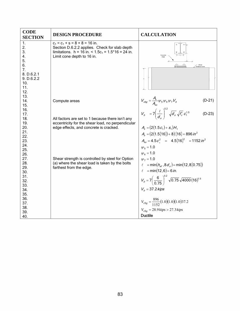
83
CODE SECTION DESIGN PROCEDURE CALCULATION
1. 2. 3. 4. 5. 6. 7. 8. D.6.2.1 9. D.6.2.2 10. 11. 12. 13. 14. 15. 16. 17. 18. 19. 20. 21. 22. 23. 24. 25. 26. 27. 28. 29. 30. 31. 32. 33. 34. 35. 36. 37. 38. 39. 40.
c1 = c1 + s = 8 + 8 = 16 in. Section D.6.2.2 applies. Check for slab depth limitations. h = 16 in. < 1.5c1 = 1.5*16 = 24 in. Limit cone depth to 16 in. Compute areas All factors are set to 1 because there isn’t any eccentricity for the shear load, no perpendicular edge effects, and concrete is cracked. Shear strength is controlled by steel for Option (a) where the shear load is taken by the bolts farthest from the edge.
Shearbreakout cone
c1
s1
1.5c11.5c1H
Concreteedge
bvo
vcbg V
AA
V 765 ψψψ= (D-21)
5.11
2.0
7 cfdd
V coo
b ′⎟⎟⎠
⎞⎜⎜⎝
⎛=
l (D-23)
( )( )
{ }( )( ) { }{ } 222
2
111
1152165.45.4
896168165.12
5.12
1incA
inA
HscA
vo
v
v
===
=+=
+=
( ) { }( )( )
( )
kipsV
V
in
dh
b
b
oef
2.37
16400075.075.0
67
.66,12min
75.08,12min8,min
0.1
0.1
0.1
5.12.0
7
6
5
=
⎟⎠
⎞⎜⎝
⎛=
==
==
=
=
=
l
l
ψψψ
( )( )( )kipskipsV
V
cbg
cbg
3.279.28
2.370.10.10.11152896
>=
=
Ductile

84
CODE SECTION DESIGN PROCEDURE CALCULATION
1. D.6.2.1 2. 3. D6.2.2 4. 5. 6. 7. 8. 9. 10. 11. 12. 13. 14. 15. 16. 17. 18. 19. 20. 21. 22. 23. 24. 25. 26. 27. 28. 29. 30. D.4.4 31. D.3.6.3 32. 33. 34. 35. 36. 37. 38.
Two bolts failure cone: Option (b) c1 is 8 in. with shear towards the edge and compression bolts loaded in shear. Compute areas. Check for slab depth limitations. h = 16 in. > 1.5c1 = 12 in. Cone depth OK. Concrete breakout strength controls for Option (b). Because bolts in compression take the shear load, no tension-shear interaction check is required. Check shear strength against shear load. ϕ is 0.70 for shear strength in concrete against breakout. Note that the 0.6 penalty factor from D.3.6.3 applies here.
Shearbreakout cone
c1
s1
1.5c11.5c1
1.5c1
H
Concreteedge
( )( ) { }{ }( )( )
{ } 222
2
111
1
28885.45.4
38412885.12
5.15.12
8
1incA
inA
cscA
inc
vo
v
v
===
=+=
+=
=
( )
kipsV
V
b
b
2.13
8400075.075.0
67 5.1
2.0
=
⎟⎠
⎞⎜⎝
⎛=
( )( )( )kipskipsV
V
cbg
cbg
3.275.17
2.130.10.10.1288384
<=
=
Nonductile ( )
( )kipsVkipsV
kipsV
VV
ucbg
cbg
cbgcbg
0.74.7
5.176.07.0
6.0
=>=
=
=
φ
φ
φφ
OK
39. STEP 8: Check concrete shear pryout 40. D.6.3 41. 42. 43. 44. D.6.3.1 45. 46. 47. 48. 49. 50. 51.
For pryout, check the tension cone for the two bolts closest to the edge. Note Ncbg computed in Step 4. Two bolts failure cone: Option (c): From Section D.6.3.1, kcp is 2 because hef > 2.5 in. This concludes the checks for the connection design. This connection is a ductile design for tension, and nonductile for shear.
( )boltskipsN cbg 28.46=
cbgcpcpg NkV = (D-28)
( ) kipskipsVcpg 3.276.938.462 >==
Ok for pryout but because nonductile in shear, apply the 0.6 penalty.
( )( )
kipsVkipsV
kipsV
VV
ucpg
cpg
cpgcpg
0.73.39
6.936.07.0
6.0
=>=
=
=
φ
φ
φφ

85
CODE SECTION DESIGN PROCEDURE CALCULATION
STEP 9: Check for Tension-Shear Interaction 1. D.7 2. 3. 4. 5. 6. D.7.3 7. 8. 9 10. 11. 12. 13. 14. 15. 16. 17. 18. 19. 20. 21.
Note that when concrete failure controls (that is, nonductile failure), there is no interaction between tension and shear (see Section 7). The tension-shear interaction is therefore checked on the steel strength and load on two bolts. Nub is the tension taken by two bolts Note that from observation, Section D.7.1 and D.7.2 do not govern. Also note that the friction between the base plate may be used to directly reduce the shear load on the connection, or may be neglected preferably for a new design interaction ratio considering both scenarios presented
( )
( )( )
kipsNNfrictionexcludingkipsVfrictionincludingkipsV
kipsNfrictionbyreducedisloadappliedif
kipskipskipsVloadappliedkipsV
sn
n
n
ub
u
u
06.2909.1239.155.15
50.350.30.70.7
=====
=−==
φφφφ
2011110912
70629515 ..
...
VV
NN
n
u
n
ub <=+=+φφ
OK for the case where friction is not considered.
20.182.009.1250.3
06.295.15
<=+=+n
u
n
ub
VV
NN
φφ
OK for the case where friction is considered.

86
1 STEP 10: Summary 1. Given 2. 3. 4. 5. 6. 7. 8.
Applied load on the embed attachment: Resulting applied load on critical two bolts:
Vu = 7 kips e = 18 in. (height of stub column above surface of concrete) Mu = Vu x e = 126.0 in.-kips Nu = 3.0 kips
kipsNub 5.15=
kipsVub 7= 9. Step 1
10. Step 4
11. Step 5
12. Step 6
13.
14. Step 2
15.
16.
17.
18.
19. Step 7
20.
21. Step 8
Design steel tensile strength
Design concrete tension breakout strength
Design concrete tension pullout strength
Design concrete side blowout strength
Design steel shear strength (includes grout and compression effects)
Design steel shear strength (excludes compression effects)
Design concrete shear breakout strength (includes the 0.6 penalty because concrete controls)
Design concrete shear pryout strength (includes the 0.6 penalty because concrete controls)
( )boltstwokipsNs 06.29=φ kipsNcbg 76.32=φ
kipsN png 3.49=φ NANsb =φ
kips.Vn 3915=φ
kipsVn 09.12=φ
kipsVcbg 4.7=φ
kipsVcpg 3.39=φ
22. iAnchor material is ASTM F1554 Gr 36. It has a tensile elongation of 23%, reduction in area of 40%, and meets the 23. definition of a ductile steel element given in D.1 (fut = 58 ksi < 1.9fy = 1.9 * 36 = 64 ksi). 24. iiSee Appendix A for recommended hole sizes for base plates, taken from AISC Design Guide 1. (American Institute 25. of Steel Construction, “Column Base Plates,” Design Guide 1, AISC, Chicago, Ill.) 26. iiiφ factor for concrete shear breakout, specified in Section D.4.4c Condition B, is assumed to convert 27. nominal shear strength resulting from friction between the base plate and the concrete to design strength.
28. iv American Institute of Steel Construction, AISC-LRFD Manual of Steel Construction, Load Resistance 29. Factor Design, V. 2, 2nd edition, Chicago, Ill., pp. 11-59. 2

87
Nu
h 1 hef
1.5
SECTION A−A
C2
1.5hefS21.5hef
Example B4(a)—Four-stud embedded plate in thin slab, tension only 1 2 Describe the checks required to assure splitting failure does not occur. 3 4 5 Given: 6 Concrete edges 7 c1 = 10 in. 8 c2 = 10 in. 9 h = 7-1/2 in. 10 s1, s2 = 6 in. 11
d0 = 1/2 in. 12 hef = 5 in. 13
14 15
Concrete material 16 fc’ = 4000 psi 17 18 Stud Material (A108)i: 19 fy = 51 ksi 20 fut = 65 ksi 21 22 Plate: 23 Fy = 36 ksi 24 25 Load: 26 Nu = 18 kips 27 28
Where Nu is the applied factored external load using 29 load factors from Appendix C of the code. 30 Assumptions: 31
• Concrete is cracked 32 • φ-factors are based on Condition B in D.4.5 of the code 33
(no supplementary reinforcement) 34 35 36 37 38 39 40 41 42 43 44 45 46
S1
1.5h
ef
1.5hefS2
C2
AN
C1
1.5h
ef
1.5hef

88
1 CODE
SECTION DESIGN PROCEDURE CALCULATION
1. STEP 1: Check the required spacing to preclude splitting failure 2. D.8.1 3. 4. 5. 6. 7.
Minimum center-to-center spacing for cast-in anchors (anchors are not torqued)
s ≥ 4d0 d0 = 1/2 in. Given 4d0 = 4 * (1/2) = 1.5 in. s = 6 in. > 2.0 in. OK
8. STEP 2: Check for minimum edge distance to preclude splitting failure 9. D.8.2 10. 11. 7.7 12. 13.
Minimum edge distance for cast-in anchors Minimum cover for No. 5 bar and smaller
cmin = c1 = c2 = 10 in. Cover required = 1.5 in. cmin = 10 in. > 1.5 in. OK
14. STEP 3: Check for minimum slab thickness to preclude splitting failure 15. D.8.5 16. 17. 18. 19. 20. 21. 22.
“The value of hef for an expansion or undercut post-installed anchor shall not exceed the greater of either 2/3 of the member thickness or the member thickness less 4 in.” No guidance is given for cast-in anchors. Therefore, assume no additional check is required for this example
7-1/2 in. slab OK for cast-in stud
23. STEP 4: Summary Step 1/ D.8.1 Step 2/ D.8.2 Step 2/ 7.7 Step 3/ D.8.5 Step 3/ D.8.5 29.
Minimum spacing for cast-in anchors Minimum edge distance Minimum cover for No. 5 bar and smaller hef
Minimum slab thickness: No code requirement for cast-in anchors
s = 6 in. ≥ 4d0 = 4 * 1/2 = 2.0 in. cmin = 10 in. Cover required = 1.5 in. < 10 in. 5 in.
30. iStud material is A108, material properties per AWS D1.1, 2004, Table 7.1, Type B stud, yield strength 31. = 51 ksi, tensile strength = 65 ksi. It has elongation of 20% and reduction in area of 50%, and meets 32. the definition of a ductile steel element given in D.1, and meets the tensile strength requirements of 33. D.5.1.2 and D.6.2.1.2: fut ≤1.9 fy (65 ≤1.9 * 51.0 = 96.9 ksi).
2

89
Example B4(b)—Four-stud rigid embedded plate in thin slab, tension only 1
2 Design an embedment using post-installed anchors. 3 4 Given: 5
Concrete edges 6 c1 = c2 = 10 in. 7 s1 = s2 = 6 in. 8 h = 7.5 in. 9 Concrete material 10 fc’ = 4000 psi 11 Stud material (A108)i 12 fy = 50 ksi 13 fut = 60 ksi 14 Plate 15 3 x 3 x 5/8 in. thick 16 Fy = 36 ksi 17 Loads 18 Nu = 18 kips 19
20 Where Nu is the applied factored external load using 21 load factors from Appendix C of the code. 22 Assumptions: 23
• Concrete is cracked 24 • φ-factors are based on Condition B in D.4.5 of the code 25
(no supplementary reinforcement) 26 27 28 29 30 31 32 33 34 35 36 37 38 39 40 41 42 43 CODE SECTION DESIGN PROCEDURE CALCULATION
44. STEP 1: Determine required steel area of the anchor 45. D.4.1.1 46. D.5.1.2 47. 48. 49. D.3.6.1 50. D.4.5 51.
Equate the external factored load to the internal design strength and solve for the required steel area of the stud. Assume embedment will be designed as ductile in accordance with D.3.6.1 (in Step 2). Therefore: φ = 0.85 for tension.
Equation
No.φNn ≥ Nu (D-1) Nn = Ns = nAsefut (D-3) Nu = 18 = φ nAsefut = 0.85 * 4.0 * Ase * 60 kips

90
CODE SECTION DESIGN PROCEDURE CALCULATION
1. 2. 3. 4. 5. 6. 7. 8. 9. 10. 11. D.5.1.2 12. 13.
Calculate nominal steel strength of selected stud. Effective Anchor diameter area, Ase in.2 1/4 0.049 3/8 0.110 Calculate the nominal steel strength Ns. Check that the material tensile and yield strengths meet requirements of D.5.1.2
Ase = Nu / φnfut min Ase = 0.088 in.2 required Use four 3/8 in. diameter studs Ase = 0.110 in.2 > 0.088 in.2 Ns = nAsefut (D-3) = 4.0 * 0.110* 60 = 26.4 kips fut =60 ≤ 1.9fy or 125 ksi fut =60 ≤ 1.9fy = 1.9*50 = 95 ksi OK
14. STEP 2: Determine required embedment length for the anchor to prevent concrete 15. breakout failure in tension 16. D.5.2 17. D.3.6.1 18. 19. 20. 21. 22. 23. 24. 25. 26. 27. 28. D.5.2.1 29. 30. 31. 32. 33. D.5.2.5 34. D.5.2.6 35. D.5.2.7 36. 37. D.5.2.2 38. 39. 40. 41. 42. 43. 44. 45. 46. 47. 48. 49. 50. 51. Table 6,
Calculate the required embedment depth for the stud to prevent concrete breakout failure. The depth will be selected so that the stud will be governed by the strength of the ductile steel element. This will produce a ductile embedment and justify the use of the φ factor for steel used previously. The requirements for a ductile design are given in D.3.6.1. To prevent concrete breakout for tension load requires that: 0.85 * Ncb ≥ Ns. Concrete breakout strength for an anchor group: For a four-stud group away from edge: See Table A1 Modification factors for: Edge effects Ψ2 Concrete cracking Ψ3 Modification post-installed Ψcp,N k = 17 for post-installed anchors Determine required embedment lengthii, hef req’d: Total length of a stud L, before weld, is equal to
From Step 1: Ns = 26.4 kips 0.85* Ncbg = Ns. Ncbg = Ns/0.85 = 26.4/0.85 = 31.05 kips
Ncbg= bNcpN
N NAA ,,321
0
ΨΨΨΨ (D-4)
AN/AN0 = 1.96 Ψ2 = 1.0 (D-10) Ψ3 = 1.4 Ψcp,N = 1 Nb = 5.1'
efc hfk lbs (D-7)
(D-7) = 5.1)4000(17 efh
= 1075 hef1.5 lbs
= 1.08 hef1.5 kips
Ncbg = 13.84 kips 13.84 = 1.96 * 1.0 * 1.4 * 1 * 1.08 hef
1.5 hef req’d = 4.78 in. Use 3/8 x 5 in. long stud hef provided = 5 - .187 + .375

91
CODE SECTION DESIGN PROCEDURE CALCULATION
1.Appendix A 2. 3. 4. 5. 6. 7. D.3.6.1 8. 9. 10. D.4.1.2 11. 12 13.
the embedment length plus the head thickness plus allowance for burn off. Standard length and head dimensions are given by the manufacturer. Typical values are given in Table 6, Appendix A. Calculate Ncb using hef provided Final check:
a) Ductility:
b) Strength
- burn off (0.125 in.) = 5.06 in. > 4.78 in. OK Ncbg =1.96 * 1.4 * 1.08 * 51.5 = 33.13 kips 0.85 * Ncbg ≥ Ns 0.85 * 33.13 = 28.16 > 26.4 kips OK φ Ncbg ≥ Nu 0.75 * 33.13 = 24.85 > 18 kips OK
14. STEP 3: Check pullout strength of anchor
15. D.5.3 16. D.3.6.1 17. 18. 19. D.5.3.1 20. 21. 22. D.5.3.4 23. 24. 25. 26. D.5.3.5 27. 28. 29. 30. 31. 32. 33. 34. D.3.6.1 35. 36. 37. 38. 39. 40. 41. 42.
Calculate the pullout strength of the stud in tension in accordance with D.5.3. Design embedment as ductile in accordance with D.3.6.1. Concrete is cracked per problem statement. Calculate pullout strength of anchor. Ψ4 = 1.0 for cracked concrete. Calculate the bearing area. From manufacturer data, stud head diameter is 0.750 in. for a 3/8 in. diameter stud (see also Table 6 in Appendix A). Design embedment as ductile, in accordance with D.3.6.1: 0.85 Npn ≥ Ns
Npn = Ψ4Np (D-14) (D-14) 4Np = 4Abrg8fc’ (D-15) =4Abrg * 8 * 4 = 128 Abrg Ψ4 = 1.0 Abrg = π * (0.75 2 – 0.3752)/4 = 0.33 in.2 Npn = 1.0 * 128 * 0.33 = 42.4 kips 0.85Npn = 0.85 * 42.4 = 36.04 kips > Ns = 26.4 kips Therefore, ductile OK Use 3/8 in. diameter x 5 in. long stud Use standard stud length OK
43. STEP 4: Check concrete side-face blowout 44. D.5.4 45. 46.
Because this stud is far away from an edge, side-face blowout Nsb will not be a factor, and will not be checked in this example.
N/A

92
CODE SECTION DESIGN PROCEDURE CALCULATION
1. STEP 5: Summary 2. 3. 4. 5. 6. 7. 8. 9. 10. 11. 12. D.4.1.2 13. 14.
Applied load Steel strength (Step 1) Concrete breakout strength (Step 2) Concrete pullout strength (Step 3) Concrete side face-blowout strength (Step 4) Design strength of stud
Nu = 18 kips φNs = 0.8 * 26.4 = 21.12 kips φ Ncbg = 0.75 * 33.13 = 24.85 kips φNpn =0 .75 * 42.4 = 36.04 kips φNsb = N/A φNn = min (φNs ,φNcb ,φNpn) = min (21.12,24.85,36.04) = 21.12 kips > Nu = 18 kips OK
15. STEP 6: Check plate thickness 16. AISC 17. 18. 19.
Because the load is applied directly over the stud, the only requirement on plate thickness is that it satisfies the minimum thickness required for stud welding.
Stud welding of 3/8 in. diameter studs is acceptable on 5/8 in. thick plate per D.6.2.3. OK
20. iStud material is A108, material properties per AWS D1.1, 2002, Table 7.1, Type B stud, yield strength = 21. 51 ksi, tensile strength = 65 ksi. It has elongation of 20% and reduction in area of 50%, meets the 22. definition of a ductile steel element given in D.1, and meets the tensile strength requirements of D.5.1.2 23. and D.6.1.2: fut ≤ 1.9fy (65 ≤ 1.9 * 51.0 = 96.9 ksi). 24. ii In the above example, the effective embedment length hef is taken to the face of the concrete. If the 25. plate was larger than the projected surface area, then the embedment length would exclude the 26. thickness of the embedded plate.
1

93
Table 1 1
MATERIALS FOR HEADED AND THREADED ANCHORS1 2
Yield Strength, Min.
Elongation, Min. Material
Grade or
Type
Diameter (in.)
Tensile Strength
Min. (ksi)
(ksi) Method (%) Length
Reduction of Area,
Min. (%)
ACI 349 Ductility Criterion
Comments
Welded Studs AWS
D1.1:2004 ASTM
A29-05 / A 108-03
B 1010 1020
1/2 to 1 65 51 0.2% 20 2 in. 50 Ductile
Structural Welding Code – Steel, Section 7, covers welded headed or welded bent studs. AWS D1.1 requires studs to be made from cold-drawn bar stock conforming to the requirements of ASTM A108.
36 1/4 to 4 58 36 0.2% 23 2 in. 40 Ductile
55 ≤2* 75 55 0.2% 21 2 in. 30 *Ductile ASTM F1554-04 (HD, T)2
105 1/4 to 3 125 105 0.2% 15 2 in. 45 Ductile
ASTM F1554, Standard Specification for Anchor Bolts, Steel, 36, 55, and 105-ksi Yield Strength is the preferred material specification for anchors. *Diameters larger than 2 in. (up to 4 in.) are available, but the reduction of area will vary for Grade 55.
≤2-1/2 125 105 0.2% 16 4D 50 Ductile 2-1/2 to
4 115 95 0.2% 16 4D 50 Ductile ASTM
A193-05 (T)
B7 Over 4 to
7 100 75 0.2% 18 4D 50 Ductile
ASTM A193, Standard Specification for Alloy-Steel and Stainless Steel Bolting Materials for High-Temperature Service: Grade B7 is an alloy steel for use in high-temperature service.
A 1/4 to 4 60 … … 18 2 in. … Ductile ASTM
A307-04 (Gr. A: HD) (Gr. C: T)
C 1/4 to 4 58 36 … 23 2 in. … Ductile
ASTM A307, Standard Specification for Carbon Steel Bolts and Studs, 60000 PSI Tensile Strength: ACI 349 specifies that elements meeting ASTM A307 shall be considered ductile. Note that Grade C conforms to tensile properties for ASTM A36.
ASTM A36-05
(T) - To 8 58 36 … 23 2 in. … Ductile
ASTM A36, Standard Specification for Carbon Structural Steel: Because ACI 318 considers ASTM A307 to be ductile, A36 will also qualify because it is the basis for ASTM A307 Grade C.
1/4 to 1 120 92 0.2% 14 4D 35 Ductile Over 1 to
1-1/2 105 81 0.2% 14 4D 35 Ductile ASTM
A449-04b (HD, T)
1 Over 1-1/2 to 3 90 58 0.2% 14 4D 35 Ductile
ASTM A449, Standard Specification for Quenched and Tempered Steel Bolts and Studs: This specification is for general high-strength applications.
Notes: 3 1. The materials listed are commonly used for concrete fasteners (anchors). Although other materials may be used (for example, ASTM 4
A 193 for high temperature applications and ASTM A 320 for low temperature applications), those listed are preferred for normal use. 5 Structural steel bolting materials, such as ASTM A 325 and A 490, are not typically available in the lengths needed for concrete 6 fastening applications. 7
8 2 Anchor type availabilities are denoted as follows: HD = headed bolt, and T = threaded bolt. 9
10

EMBEDMENT DESIGN EXAMPLES
APPENDIX A - TABLES
ACI 349.2R-XX
1 Diameter2 Nominal steel strength Ns
2 d0, Gross3 AD Effective4 Ase Stud5 Threaded6
3 in. n in.2 in.2 kips kips4 0.250 20 0.049 0.032 3.2 1.85 0.375 16 0.110 0.078 7.2 4.567 0.500 13 0.196 0.142 12.8 8.28 0.625 11 0.307 0.226 19.9 13.19 0.750 10 0.442 0.334 28.7 19.410 0.875 9 0.601 0.462 39.1 26.81112 1.000 8 0.785 0.606 51.1 35.113 1.125 7 0.994 0.763 64.6 44.314 1.250 7 1.227 0.969 79.8 56.215 1.375 6 1.485 1.16 96.5 67.31617 1.500 6 1.767 1.41 114.9 81.518 1.750 5 2.405 1.90 156.3 110.21919 2.000 4.5 3.142 2.50 204.2 144.9202122 Notes2324 1. Table taken from AISC, Manual of Steel Construction25 2. Concrete breakout strength is limited to anchor diameter26 no greater than 2 in. and length no greater than 25 in. (D.4.2.2) 27 3. Use Gross Area, AD, for studs28 4. Use Effective Area, Ase, for threaded anchors29 (Note - Ase is same as AK in AISC)30 Ase = 0.7854*(d0-(0.9743/n))2
31 5. Ns = AD*fut; fut = 65 ksi; See Table 1 for other materials A108 F1554 Gr. 3632 6. Ns = Ase*fut; fut = 58 ksi; See Table 1 for other materials 65 58
Table 2 Threaded fastener dimensions1
Threads per inch
Effective area
fut (ksi)
94

EMBEDMENT DESIGN EXAMPLES
APPENDIX A - TABLES
ACI 349.2R-XX
1 F1554 Grade 36 Ductility factor Fd 0.85
2
Ns = Ase*fut
3Nominal bolt
diameterfut
ksi
4d0,
Gross area of bolt, AD
Effective area, Ase
2 58 3000 4000 5000 6000 8000
5 in. in.2 in.2 kips in. in. in. in. in.6 0.250 0.049 0.032 1.8 1.4 1.3 1.2 1.1 1.07 0.375 0.110 0.078 4.5 2.5 2.3 2.1 2.0 1.88 0.500 0.196 0.142 8.2 3.8 3.4 3.2 3.0 2.79 0.625 0.307 0.226 13.1 5.2 4.7 4.4 4.1 3.7
10 0.750 0.442 0.334 19.4 6.7 6.1 5.7 5.3 4.811 0.875 0.601 0.462 26.8 8.3 7.6 7.0 6.6 6.01213 1.000 0.785 0.606 35.1 10.0 9.1 8.4 7.9 7.214 1.125 0.994 0.763 44.3 11.6 10.6 9.8 9.2 8.415 1.250 1.227 0.969 56.2 13.6 12.4 11.5 10.8 9.816 1.375 1.485 1.16 67.3 15.4 14.0 13.0 12.2 11.117 1.500 1.767 1.41 81.5 17.5 15.9 14.7 13.9 12.618 1.750 2.405 1.90 110.2 21.3 19.4 18.0 16.9 15.41920 2.000 3.142 2.50 144.9 25.6 23.3 21.6 20.3 18.5212222 Notes:23 1. FdNb = Ns; Fd = 0.85; Nb = 24(fc').5*hef
1.5; hef = (Ns/(0.85*24*fc'.5)2/3
24 2. Ase taken from Table 2.
95
Concrete strength, psi
Table 3(a) Required embedment for ductile behavior,free field, single anchor
Required embedment depth hef for ductile behavior1
Bolt areas

EMBEDMENT DESIGN EXAMPLES
APPENDIX A - TABLES
ACI 349.2R-XX
1 F1554 Grade 105 Ductility factor Fd 0.85
2
Ns = Ase*fut
3Nominal bolt
diameterfut ksi
4d0
Gross area of bolt AD,
Effective area Ase
2, 105 3000 4000 5000 6000 8000
5 in. in.2 in.2 kips in. in. in. in. in.
6 0.250 0.049 0.032 3.3 2.1 1.9 1.8 1.6 1.57 0.375 0.110 0.078 8.2 3.8 3.4 3.2 3.0 2.78 0.500 0.196 0.142 14.9 5.6 5.1 4.7 4.5 4.19 0.625 0.307 0.226 23.7 7.7 7.0 6.5 6.1 5.5
10 0.750 0.442 0.334 35.1 10.0 9.0 8.4 7.9 7.211 0.875 0.601 0.462 48.5 12.3 11.2 10.4 9.8 8.91213 1.000 0.785 0.606 63.6 14.8 13.4 12.5 11.7 10.714 1.125 0.994 0.763 80.1 17.3 15.7 14.6 13.7 12.415 1.250 1.227 0.969 101.8 20.2 18.4 17.1 16.1 14.616 1.375 1.485 1.16 121.8 22.8 20.7 19.2 18.1 16.517 1.500 1.767 1.41 147.6 25.9 23.6 21.9 20.6 18.718 1.750 2.405 1.90 199.4 31.7 28.8 26.7 25.2 22.91920 2.000 3.142 2.50 262.3 38.1 34.6 32.1 30.2 27.42122 Notes:22 1. FdNb = Ns; Fd = 0.85; Nb = 24(fc').5*hef
1.5; hef = (Ns/(0.85*24*fc'.5)2/3
23 2. Ase taken from Table 2.
96
Concrete strength, psi
Required embedment depth hef for ductile behavior1
Bolt areas
Table 3(b) Required embedment for ductile behavior,free field, single anchor

EMBEDMENT DESIGN EXAMPLES
APPENDIX A - TABLES
ACI 349.2R-XX
1 Stud - fut 65 Ductility Factor: Fd 0.85
2
Ns = Ase*fut
3Nominal bolt
diameterfut ksi
4d0
Gross area of bolt AD,
Effective area Ase
2, 105 3000 4000 5000 6000 8000
5 in. in.2 in.2 kips in. in. in. in. in.
6 0.250 0.049 0.032 5.2 2.8 2.5 2.3 2.2 2.0
7 0.375 0.110 0.078 11.6 4.8 4.3 4.0 3.8 3.48 0.500 0.196 0.142 20.6 7.0 6.3 5.9 5.5 5.09 0.625 0.307 0.226 32.2 9.4 8.5 7.9 7.5 6.8
10 0.750 0.442 0.334 46.4 12.0 10.9 10.1 9.5 8.611 0.875 0.601 0.462 63.1 14.7 13.4 12.4 11.7 10.61213 1.000 0.785 0.606 82.5 17.6 16.0 14.8 14.0 12.714 1.125 0.994 0.763 104.4 20.6 18.7 17.4 16.3 14.815 1.250 1.227 0.969 128.9 23.7 21.5 20.0 18.8 17.116 1.375 1.485 1.16 155.9 26.9 24.4 22.7 21.4 19.417 1.500 1.767 1.41 185.6 30.2 27.4 25.5 24.0 21.818 1.750 2.405 1.90 252.6 37.1 33.7 31.3 29.5 26.81920 2.000 3.142 2.50 329.9 44.3 40.3 37.4 35.2 32.02122 Notes:22 1. FdNb = Ns; Fd = 0.85; Nb = 24(fc').5*hef
1.5; hef = (Ns/(0.85*24*fc'.5)2/3
23 2. Ase taken from Table 2.
97
Bolt areas Concrete strength, psi
Required embedment depth hef for ductile behavior1
Table 3(c) Required embedment for ductile behavior,free field, single anchor

EMBEDMENT DESIGN EXAMPLES
APPENDIX A - TABLES
ACI 349.2R-XX
1
23
4Ductility factor
Fd 0.85 5
6
7
8Nominal bolt
diameter
9 d0,Gross area of
bolt, AD
Effective area, Ase
2 Width F, Width C, Height H,
Gross area of head AH
3, based on width
FNet bearing area, Abrg
4 3000 4000 5000 6000 8000 fut = 58
Required f'c7
for ductile behavior fut = 75
Required f'c
7 for ductile
behavior fut = 105
Required f'c7
for ductile behavior
10 in. in.2 in.2 in. in. in. in.2 in.2 kips kips kips kips kips kips psi kips psi kips psi11 Head size12 0.250 0.049 0.032 0.375 0.500 0.188 0.14 0.09 2 2 3 4 5 1.8 3000 2.4 3800 3.3 540013 0.375 0.110 0.078 0.563 0.813 0.250 0.32 0.21 4 6 7 8 11 4.5 3200 5.9 4200 8.2 580014 0.500 0.196 0.142 0.750 1.063 0.313 0.56 0.37 7 10 12 15 20 8.2 3300 10.6 4300 14.9 600015 0.625 0.307 0.226 0.938 1.313 0.438 0.88 0.57 12 16 19 23 31 13.1 3400 17.0 4400 23.7 610016 0.750 0.442 0.334 1.125 1.563 0.500 1.27 0.82 17 22 28 34 45 19.4 3500 25.1 4500 35.1 630017 0.875 0.601 0.462 1.313 1.875 0.625 1.72 1.12 23 31 38 46 61 26.8 3500 34.6 4500 48.5 64001819 1.000 0.785 0.606 1.500 2.125 0.688 2.25 1.46 30 40 50 60 80 35.1 3500 45.4 4600 63.6 640020 1.125 0.994 0.763 1.688 2.375 0.750 2.85 1.85 38 50 63 76 101 44.3 3500 57.2 4500 80.1 640021 1.250 1.227 0.969 1.875 2.625 0.875 3.52 2.29 47 62 78 93 124 56.2 3600 72.7 4700 101.8 650022 1.375 1.485 1.16 2.063 2.938 0.938 4.25 2.77 56 75 94 113 151 67.3 3600 87.0 4600 121.8 650023 1.500 1.767 1.41 2.250 3.188 1.000 5.06 3.30 67 90 112 134 179 81.5 3600 105.4 4700 147.6 660024 1.750 2.405 1.902526 2.000 3.142 2.5027 Nut Size 8
28 0.250 0.049 0.032 0.438 0.625 0.250 0.19 0.14 2.9 3.9 4.8 5.8 7.7 1.8 1900 2.4 2500 3.3 350029 0.375 0.110 0.078 0.625 0.875 0.313 0.39 0.28 5.7 7.6 9.5 11.4 15.2 4.5 2400 5.9 3100 8.2 430030 0.500 0.196 0.142 0.813 1.125 0.438 0.66 0.46 9.5 12.6 15.8 18.9 25.2 8.2 2600 10.6 3400 14.9 470031 0.625 0.307 0.226 1.000 1.438 0.563 1.00 0.69 14.1 18.9 23.6 28.3 37.7 13.1 2800 17.0 3600 23.7 5000
32 Notes:33 1 Dimensions taken from AISC Steel Design Manual34 2 See Table 2 for definition of Ase
35 3 AH = F2 or AH = 1.5F2tan30
36 4 Abrg = AH-AD
37 5 Np=8f'cAbrg (D5.3.4); Fd=factor for ductile behavior (D.3.6.1)
38 6 Ns = Asefut
39 7 f'c req'd =f'c(Ns/NpFd)40 8 For other diameters, the nut dimensions match the head
98
ASTM F 1554 Gr 55 ASTM F 1554 Gr 105
Table 4(a)
Bolt areas
Anchor head and nut dimensions and concrete pullout strength (square head)
Concrete pullout strength, Np * Fd5
f'c (psi)
Threaded anchor steel strength Ns6
ASTM F 1554 Gr 36
d0

EMBEDMENT DESIGN EXAMPLES
APPENDIX A - TABLES
ACI 349.2R-XX
1
23
4Ductility factor
Fd 0.85 567
8Nominal bolt
diameter
9 d0,Gross area of
bolt, AD
Effective area, Ase
2 Width F, Width C, Height H,
Gross area of head AH
3, based on width
FNet bearing area, Abrg
4 3000 4000 5000 6000 8000 fut = 58
Required f'c7
for ductile behavior fut = 75
Required f'c
7 for ductile
behavior fut = 105
Required f'c7
for ductile behavior
10 in. in.2 in.2 in. in. in. in.2 in.2 kips kips kips kips kips kips psi kips psi kips psi1112 0.250 0.049 0.032 0.438 0.500 0.188 0.17 0.12 2 3 4 5 6 1.8 2300 2.4 3000 3.3 420013 0.375 0.110 0.078 0.563 0.625 0.250 0.27 0.16 3 4 6 7 9 4.5 4100 5.9 5300 8.2 740014 0.500 0.196 0.142 0.750 0.875 0.375 0.49 0.29 6 8 10 12 16 8.2 4200 10.6 5400 14.9 750015 0.625 0.307 0.226 0.938 1.063 0.438 0.76 0.45 9 12 15 19 25 13.1 4200 17.0 5500 23.7 770016 0.750 0.442 0.334 1.125 1.313 0.500 1.10 0.65 13 18 22 27 36 19.4 4400 25.1 5600 35.1 790017 0.875 0.601 0.462 1.313 1.500 0.563 1.49 0.89 18 24 30 36 48 26.8 4400 34.6 5700 48.5 80001819 1.000 0.785 0.606 1.500 1.750 0.688 1.95 1.16 24 32 40 47 63 35.1 4400 45.4 5700 63.6 800020 1.125 0.994 0.763 1.688 1.938 0.750 2.47 1.47 30 40 50 60 80 44.3 4400 57.2 5700 80.1 800021 1.250 1.227 0.969 1.875 2.188 0.875 3.04 1.82 37 49 62 74 99 56.2 4500 72.7 5900 101.8 820022 1.375 1.485 1.16 2.063 2.375 0.938 3.68 2.20 45 60 75 90 120 67.3 4500 87.0 5800 121.8 810023 1.500 1.767 1.41 2.250 2.625 1.000 4.38 2.62 53 71 89 107 142 81.5 4600 105.4 5900 147.6 830024 1.750 2.405 1.90 2.625 3.000 1.188 5.97 3.56 73 97 121 145 194 110.2 4500 142.5 5900 199.4 82002526 2.000 3.142 2.50 3.000 3.438 1.375 7.79 4.65 95 127 158 190 253 144.9 4600 187.4 5900 262.3 83002728 Notes:29 1 Dimensions taken from AISC Steel Design Manual30 2 See Table 2 for definition of Ase
31 3 AH = F2 or AH = 1.5F2tan304 Abrg = AH-AD
32 5 Np=8f'cAbrg (D5.3.4); Fd=factor for ductile behavior (D.3.6.1)
33 6 Ns = Asefut
34 7 f'c req'd = f'c(Ns/NpFd)353637 99
ASTM F 1554 Gr 105Bolt areas
ASTM F 1554 Gr 36 ASTM F 1554 Gr 55f'c (psi)
Threaded anchor steel strength Ns6
Anchor head dimensions and concrete pullout strength (hex head)
Table 4(b)
Concrete pullout strength, Np * Fd5
d0

EMBEDMENT DESIGN EXAMPLES
APPENDIX A - TABLES
ACI 349.2R-XX
1
23
4 Ductility factor Fd 0.85 567
8Nominal bolt
diameter
9 d0,Gross area of
bolt, AD
Effective area, Ase
2 Width F, Width C, Height H,
Gross area of head AH
3, based on width
FNet bearing area, Abrg
4 3000 4000 5000 6000 8000 fut = 58
Required f'c7
for ductile behavior fut = 75
Required f'c
7 for ductile
behavior fut = 105
Required f'c7
for ductile behavior
10 in. in.2 in.2 in. in. in. in.2 in.2 kips kips kips kips kips kips psi kips psi kips psi11 0.250 0.049 0.03212 0.375 0.110 0.07813 0.500 0.196 0.142 0.875 1.000 0.375 0.66 0.47 10 13 16 19 25 8.2 2600.0 10.6 3400 14.9 470014 0.625 0.307 0.226 1.063 1.250 0.438 0.98 0.67 14 18 23 27 36 13.1 2900.0 17.0 3700 23.7 520015 0.750 0.442 0.334 1.250 1.438 0.500 1.35 0.91 19 25 31 37 50 19.4 3100.0 25.1 4000 35.1 570016 0.875 0.601 0.462 1.438 1.688 0.563 1.79 1.19 24 32 40 48 65 26.8 3300.0 34.6 4300 48.5 60001718 1.000 0.785 0.606 1.625 1.875 0.688 2.29 1.50 31 41 51 61 82 35.1 3400.0 45.4 4400 63.6 620019 1.125 0.994 0.763 1.813 2.063 0.750 2.85 1.85 38 50 63 76 101 44.3 3500.0 57.2 4500 80.1 640020 1.250 1.227 0.969 2.000 2.313 0.875 3.46 2.24 46 61 76 91 122 56.2 3700.0 72.7 4800 101.8 670021 1.375 1.485 1.16 2.188 2.500 0.938 4.14 2.66 54 72 90 108 145 67.3 3700.0 87.0 4800 121.8 670022 1.500 1.767 1.41 2.375 2.750 1.000 4.88 3.12 64 85 106 127 170 81.5 3800.0 105.4 5000 147.6 700023 1.750 2.405 1.90 2.750 3.500 1.188 6.55 4.14 85 113 141 169 225 110.2 3900.0 142.5 5100 199.4 71002425 2.000 3.142 2.50 3.125 3.625 1.375 8.46 5.32 108 145 181 217 289 144.9 4000.0 187.4 5200 262.3 7300262728 Notes:29 1 Dimensions taken from AISC Steel Design Manual30 2 See Table 2 for definition of Ase
31 3 AH = F2 or AH = 1.5F2tan30
32 4 Abrg = AH-AD
33 5 Np=8f'cAbrg (D5.3.4); Fd=factor for ductile behavior (D.3.6.1)
34 6 Ns = Asefut
35 7 f'c req'd =f'c(Ns/NpFd)363738 100
Concrete pullout strength, Np * Fd5
f'c (psi)
Threaded anchor steel strength Ns6
ASTM F 1554 Gr 36 ASTM F 1554 Gr 55 ASTM F 1554 Gr 105Bolt areas
Anchor head dimensions and concrete pullout strength (heavy hex)
Table 4(c)
d0

EMBEDMENT DESIGN EXAMPLES
APPENDIX A - TABLES
ACI 349.2R-XX
1
2Ductility factor Fd 0.85
3 Hardened washers: SAE dimensions
4
5Nominal bolt
diameter Equivalent diameters OVERHANGf'c, psi
ASTM F1554 Gr
36
ASTM F1554 Gr
55
ASTM F1554 Gr
105
6 d0
Gross area of bolt AD,
Effective area, Ase
2, OD ID Thickness H, Extra thickGross area of
head AH3,
Net bearing area Abrg
4, Square HexHeavy
hex Square HexHeavy
hex 3000 4000 5000 6000 8000 fut = 58
Required f'c7 for ductile
behavior fut = 75
Required f'c7 for ductile
behavior fut = 105
Required f'c7 for ductile
behavior7 in. in2 in2 in. in. in. in2 in2 kips kips kips kips kips k psi k ksi k ksi89 0.250 0.049 0.032 0.563 0.281 .051/.080 0.25 0.20 0.42 0.46 0.07 0.05 4 5 7 8 11 1.8 1400 2.4 1800 3.3 2500
10 0.375 0.110 0.078 0.813 0.406 .051/.080 0.52 0.41 0.63 0.59 0.09 0.11 8 11 14 17 22 4.5 1600 5.9 2100 8.2 300011 0.500 0.196 0.142 1.167 0.531 .074/.121 1.07 0.87 0.85 0.79 0.92 0.16 0.19 0.12 18 24 30 36 47 8.2 1400 10.6 1800 14.9 250012 0.625 0.307 0.226 1.313 0.656 .074/.121 1.35 1.05 1.06 0.98 1.12 0.13 0.16 0.10 21 28 36 43 57 13.1 1800 17.0 2400 23.7 330013 0.750 0.442 0.334 1.469 0.813 .108/.160 1.69 1.25 1.27 1.18 1.31 0.10 0.14 0.08 26 34 43 51 68 19.4 2300 25.1 2900 35.1 410014 0.875 0.601 0.462 1.750 0.938 .108/.160 2.41 1.80 1.48 1.38 1.51 0.13 0.19 0.12 37 49 61 74 98 26.8 2200 34.6 2800 48.5 40001516 1.000 0.785 0.606 2.000 1.063 .108/.160 3.14 2.36 1.69 1.58 1.71 0.15 0.21 0.15 48 64 80 96 128 35.1 2200 45.4 2800 63.6 400017 1.125 0.994 0.763 2.250 1.250 .136/.177 .305/.375 3.98 2.98 1.90 1.77 1.90 0.17 0.24 0.17 61 81 101 122 162 44.3 2200 57.2 2800 80.1 400018 1.250 1.227 0.969 2.500 1.375 .136/.192 4.91 3.68 2.12 1.97 2.10 0.19 0.27 0.20 75 100 125 150 200 56.2 2200 72.7 2900 101.8 410019 1.375 1.485 1.16 2.750 1.500 .136/.213 5.94 4.45 2.33 2.17 2.30 0.21 0.29 0.23 91 121 151 182 242 67.3 2200 87.0 2900 121.8 400020 1.500 1.767 1.41 3.000 1.625 .153/.213 7.07 5.30 2.54 2.36 2.49 0.32 0.25 108 144 180 216 288 81.5 2300 105.4 2900 147.6 410021 1.750 2.405 1.90 3.375 1.875 .153/.213 8.95 6.54 2.76 2.89 0.31 0.24 133 178 222 267 356 110.2 2500 142.5 3200 199.4 45002223 2.000 3.142 2.50 3.750 2.125 .153/.213 11.04 7.90 3.15 3.28 0.30 0.23 161 215 269 322 430 144.9 2700 187.4 3500 262.3 4900242627 Hardened washers: U.S standard dimensions
28
29Nominal bolt
diameter
30 d0
Gross area of bolt AD,
Effective area, Ase
2, OD ID Thickness H,Gross area of
head AH3,
Net bearing area Abrg
4, 3000 4000 5000 6000 8000 fut = 58
Required f'c7 for ductile
behavior fut = 75
Required f'c7
for ductile behavio
rfut = 105
Required f'c7
for ductile behavio
r31 in. in2 in2 in. in. in. in.2 in.2 kips kips kips kips kips k ksi k ksi k ksi32 0.250 0.049 0.032 0.750 0.313 .064/.080 0.44 0.39 8 11 13 16 21 1.8 700 2.4 900 3.3 130033 0.375 0.110 0.078 1.000 0.438 .079/.093 0.79 0.67 14 18 23 28 37 4.5 1000 5.9 1300 8.2 180034 0.500 0.196 0.142 1.375 0.375 .122/.146 1.48 1.29 26 35 44 53 70 8.2 900 10.6 1200 14.9 170035 0.625 0.307 0.226 1.750 0.656 .136/.160 2.41 2.10 43 57 71 86 114 13.1 900 17.0 1200 23.7 170036 0.750 0.442 0.334 2.000 0.813 .136/.160 3.14 2.70 55 73 92 110 147 19.4 1100 25.1 1400 35.1 190037 0.875 0.601 0.462 2.250 0.938 .136/.160 3.98 3.37 69 92 115 138 184 26.8 1200 34.6 1500 48.5 21003839 1.000 0.785 0.606 2.500 1.063 .136/.192 4.91 4.12 84 112 140 168 224 35.1 1300 45.4 1600 63.6 230040 1.125 0.994 0.763 2.750 1.250 .126/.192 5.94 4.95 101 135 168 202 269 44.3 1300 57.2 1700 80.1 240041 1.250 1.227 0.969 3.000 1.375 .126/.192 7.07 5.84 119 159 199 238 318 56.2 1400 72.7 1800 101.8 260042 1.375 1.485 1.160 3.250 1.500 .126/.192 8.30 6.81 139 185 232 278 371 67.3 1500 87.0 1900 121.8 260043 1.500 1.767 1.405 3.500 1.625 .153/.213 9.62 7.85 160 214 267 320 427 81.5 1500 105.4 2000 147.6 280044 1.750 2.405 1.899 4.250 1.875 .153/.213 14.19 11.78 240 320 401 481 641 110.2 1400 142.5 1800 199.4 25004546 2.000 3.142 2.50 4.500 2.125 .153/.213 15.90 12.76 260 347 434 521 694 144.9 1700 187.4 2200 262.3 30004748 Notes:49 1 Hardened Washers to S.A.E. Dimensions (Material = ASTM 563 )50 2 See Table 2 for definition of Ase
51 3 AH = π (OD)2/4
52 4 Abrg = AH-AD
53 5 Np=8f'cAbrg (D5.3.4); Fd=0.85 for ductile behavior (D.3.6.1)
54 6 Ns = Asefut
55 7 f'c req'd = fcp(Ns/NpFd)
101
Table 5
Threaded anchor steel strength Ns6Bolt Areas
Bolt Areas
ASTM F 1554 Gr 105
Washer dimensions
Hardened washer dimensions1 and concrete pullout strength
f'c (ksi) ASTM F 1554 Gr 36
ASTM F 1554 Gr 55
Concrete pullout strength, Np * Fd5 Threaded anchor steel strength Ns
6Washer dimensions
Concrete pullout strength, Np * Fd5