337 extreme mechanics letters - harvard university
TRANSCRIPT

Fiber-reinforced tough hydrogelsThe Harvard community has made this
article openly available. Please share howthis access benefits you. Your story matters
Citation Illeperuma, Widusha R.K., Jeong-Yun Sun, Zhigang Suo, and JoostJ. Vlassak. 2014. “Fiber-Reinforced Tough Hydrogels.” ExtremeMechanics Letters (November). doi:10.1016/j.eml.2014.11.001.
Published Version doi:10.1016/j.eml.2014.11.001
Citable link http://nrs.harvard.edu/urn-3:HUL.InstRepos:13919163
Terms of Use This article was downloaded from Harvard University’s DASHrepository, and is made available under the terms and conditionsapplicable to Open Access Policy Articles, as set forth at http://nrs.harvard.edu/urn-3:HUL.InstRepos:dash.current.terms-of-use#OAP

1
Fiber-reinforced tough hydrogels
Widusha R. K. Illeperuma1, Jeong-Yun Sun2, Zhigang Suo1,* and Joost J. Vlassak1,*
1School of Engineering and Applied Sciences, Harvard University, Cambridge, MA 02138, USA
2Department of Material Science and Engineering, Seoul National University, Seoul 151-742,
South Korea
* Email: [email protected], [email protected]
Abstract
Using strong fibers to reinforce a hydrogel is highly desirable but difficult. Such a composite
would combine the attributes of a solid that provides strength and a liquid that transports
matter. Most hydrogels, however, are brittle, allowing the fibers to cut through the hydrogel
when the composite is loaded. Here we circumvent this problem by using a recently developed
tough hydrogel. We fabricate a composite using an alginate-polyacrylamide hydrogel reinforced
with a random network of stainless steel fibers. Because the hydrogel is tough, the composite
does not fail by the fibers cutting the hydrogel; instead, it fails by the fibers pulling out of the
hydrogel against friction. Both stiffness and strength can be increased significantly by adding
fibers to the hydrogel. Before failure the composite dissipates a significant amount of energy, at
a tunable level of stress, attaining large deformation. Potential applications of tough hydrogel
composites include energy-absorbing helmets, tendon repair surgery, and stretchable biometric
sensors.
Key words: Tough hydrogel, Hydrogel composite, Fiber pullout
1. Introduction
Hydrogels are soft materials that consist of cross-linked networks of hydrophilic polymer chains
dispersed in water. They have many applications including scaffolds in tissue engineering [1],
carriers for drug delivery [2], and valves for microfluidic devices [3]. Many applications of
2
hydrogels rely on the combined attributes of a solid that provides strength and a liquid that
transports matter. Most existing hydrogels, however, are brittle, with fracture energies on the
order of 10 J/m2 [4,5]. This limits their use in structural applications where they are subject to
mechanical loading. This problem could be circumvented by reinforcing the hydrogels with
fibers to improve their mechanical behavior [6]. This effort is hampered, however, by the low
toughness of hydrogels: as the composite is loaded, the fibers cut through the hydrogel matrix,
destroying the synergy between fibers and matrix, and leading to rapid failure of the composite.
A hydrogel-based composite is only effective if the hydrogel matrix is tough enough to resist the
fibers cutting through the matrix. Cartilage is one example of such a composite taken from
nature: cartilage consists of a collagen fiber-reinforced proteoglycan gel. It contains more than
70% water, but is remarkably stiff and tough [7,8]. It comes as no surprise, then, that hydrogel-
based composites are being actively explored for use as synthetic tissues and in biocompatible
products [9-16].
Many attempts have been made to improve the toughness of hydrogels [13, 15-18]. Double-
network hydrogels were the first class of hydrogels to exhibit significant fracture toughness, with
fracture energies in the range of 100-1000 Jm-2 [15]. Recently, we developed a new group of
hybrid hydrogels synthesized from polymers that form networks with covalent and ionic cross-
links, and that have an extraordinary combination of toughness and stretchability [19]. These
hybrid gels consist of a covalently cross-linked polyacrylamide (PAAm) network and an ionically
cross-linked alginate network, and can attain fracture energies as large as 9000 Jm-2. The need
for a tough composite matrix is illustrated graphically in Figure 1, where we use a metal wire to
cut through two different types of hydrogels, a standard technique for measuring the fracture
toughness of foods and soft gels [20,21]. Two examples are shown: (1) a brittle alginate gel and
(2) a tough alginate-polyacrylamide hybrid hydrogel. The difference between the gels is obvious.
The alginate gel is readily cut by the wire; the hybrid gel deforms elastically, but resists being
cut. Thus an alginate matrix would result in a composite with poor mechanical properties. The

3
hybrid gel, on the other hand, would make a very good matrix in a fiber-reinforced composite.
Such a composite would have significantly better stiffness and strength than the hybrid
hydrogel, and could be used in structural applications. Lin et al [13] have investigated the
toughening mechanism of alginate-polyacrylamide hydrogels reinforced by a stretchy fiber mesh
fabricated from thermoplastic polymers. When a notched sample of such a composite is
deformed, the hydrogel matrix maintains the integrity of the sample, while fracture of the fibers
in the bridging zone dissipates mechanical energy.
In this study we investigate the mechanical behavior of composites that consist of a tough
alginate-polyacrylamide hydrogel matrix reinforced with a random network of stiff fibers, for
which we conveniently use stainless steel wool. Steel wool fibers are strong and can easily create
a random continuous fiber network – they have been used for this purpose in a number of
applications [22,23]. We evaluate the stress-strain curves of the fiber-reinforced gels and
evaluate the mechanism by which they fail.
2. Experimental
2.1 Synthesis of fiber reinforced hydrogels: Powders of alginate (FMC Biopolymer, LF 20/40)
and acrylamide (Sigma, A8887) were dissolved in deionized water. After the powders were fully
dissolved, the solution was held at 350C for 1 hour. Weights of alginate and acrylamide were
fixed at 1:6, and the water content was fixed at 86 wt.%. Ammonium persulfate (AP; Sigma,
A9164), 0.0017 times the weight of acrylamide, was added as a photo initiator for the acrylamide
polymerization process. N,N-methylenebisacrylamide (MBAA; Sigma, M7279), 0.0006 times
the weight of the acrylamide, was added as the cross-linker for the acrylamide. N,N,N’,N’-
tetramethylethylenediamine (TEMED; Sigma, T7024), 0.0025 times the weight of acrylamide,
was added as the cross-linking accelerator for the polyacrylamide. Calcium sulfate slurry
(CaSO4•2H2O; Sigma, 31221), 0.1328 times the weight of alginate, was added as the ionic cross-
linker for alginate. Stainless steel wool (Type 316, fine, McMaster-Carr 7364T74) with an

4
average cross-sectional area of the fibers of ~ 80µm × 70µm was chosen to provide the
reinforcing fibers. The fibers in this type of steel wool are arbitrarily oriented and have lengths
that exceed the sample dimensions. After the wool was distributed evenly inside dumbbell-
shaped molds, the gel solution was poured into the molds and covered with a glass plate. Before
casting the gel solution, the steel wool was thoroughly wetted with the solution to reduce the
formation of bubbles inside the samples. The composite samples were then cured at room
temperature by exposing them for eight minutes to ultraviolet light with a wavelength of 350 nm
(OAI LS 30 UV flood exposure system, 1.92W/cm2 power density). The samples were kept in a
sealed container at room temperature for one day to ensure complete reaction. The weight
fraction of steel wool in the composite hybrid gels was varied from 0 to 12 wt%.
2.2 Wire cutting test: Hydrogel samples with a diameter of 35mm and a thickness of 17mm were
fabricated from an unreinforced alginate-polyacrylamide hybrid hydrogel and an alginate
hydrogel (Fig. 1). Wire cutting tests were performed in air, at room temperature, using a tensile
tester (Instron model 3342) with a 1000 N load cell. A 580 µm diameter steel wire was pulled
through the specimen at a displacement rate 10 mm/min.
2.3 Tensile test: Tensile experiments were performed using the dumbbell-shaped samples. The
gauge sections of the samples were 35mm long, 15mm wide, and 3mm thick (figure 2a). The
wide sections of the samples were glued between two acrylic plates of dimensions
10 × 20 × 3mm3 using super glue (VWR, 500031-578) and the acrylic plate/gel sandwiches were
inserted into the grips of the tensile tester. Measurements were performed at room temperature
in air using a 1000 N load cell. The force-displacement curves were measured at a displacement
rate of 10mm/min. Tests were performed until rupture of the samples. The force-extension
curve for steel wool was measured by performing measurements on the same amount of steel
wool, randomly distributed in the same volume as the composite samples. Five experiments
were performed per condition.
5
2.4 Fiber pullout test: The friction between the hydrogel matrix and the stainless steel fibers was
measured using a fiber pullout test. A long fiber was embedded inside an alginate-
polyacrylamide hydrogel during synthesis of the gel, such that a significant length of the fiber
extended outside the gel on both sides of the sample. The samples had a height of 75mm, width
of 15mm, and thickness of 3 mm. Fiber dimensions were measured at three locations along the
length of each fiber by means of optical microscopy. The samples were mounted in the tensile
tester and one end of the fiber was attached to the grip of the tensile tester. Pullout tests were
performed in air, at room temperature, using a 1000 N load cell. Force-displacement curves
were measured at a displacement rate of 10 mm/min. Tests were performed on five different
samples.
3. Results and discussion
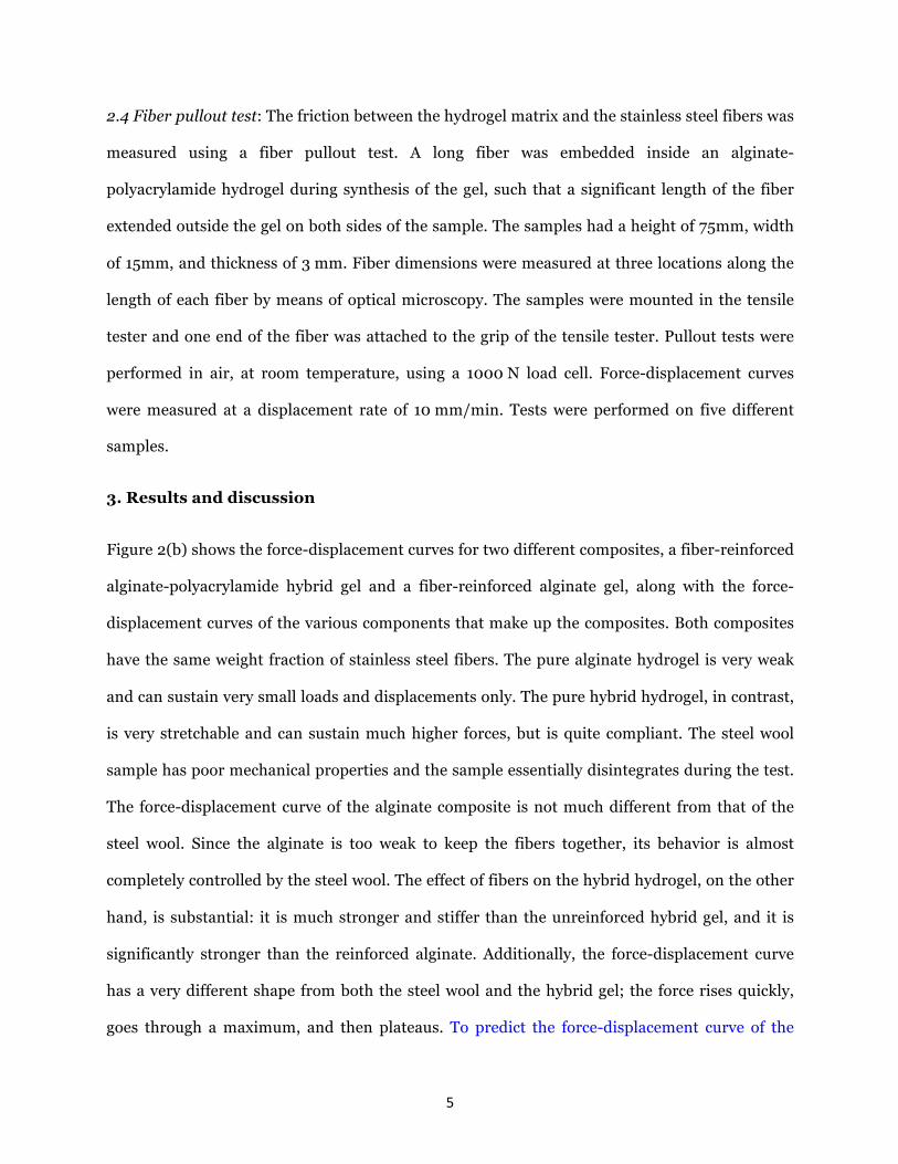
Figure 2(b) shows the force-displacement curves for two different composites, a fiber-reinforced
alginate-polyacrylamide hybrid gel and a fiber-reinforced alginate gel, along with the force-
displacement curves of the various components that make up the composites. Both composites
have the same weight fraction of stainless steel fibers. The pure alginate hydrogel is very weak
and can sustain very small loads and displacements only. The pure hybrid hydrogel, in contrast,
is very stretchable and can sustain much higher forces, but is quite compliant. The steel wool
sample has poor mechanical properties and the sample essentially disintegrates during the test.
The force-displacement curve of the alginate composite is not much different from that of the
steel wool. Since the alginate is too weak to keep the fibers together, its behavior is almost
completely controlled by the steel wool. The effect of fibers on the hybrid hydrogel, on the other
hand, is substantial: it is much stronger and stiffer than the unreinforced hybrid gel, and it is
significantly stronger than the reinforced alginate. Additionally, the force-displacement curve
has a very different shape from both the steel wool and the hybrid gel; the force rises quickly,
goes through a maximum, and then plateaus. To predict the force-displacement curve of the

6
hydrogel composite at small displacements, the curves for steel wool and hydrogel are vertically
added and plotted in figure 2(c). Evidently, the experimental curve does not follow the rule of
mixtures based on the behavior of the constituents. This is understood as follows: the fibers in
the steel wool are held together by entanglement only, they are not bonded in any way. During
tensile testing, the fibers slide with respect to one another. Consequently, the tensile behavior is
not representative of the mechanical behavior of the fibers; instead it is a measure for the
frictional resistance encountered during fiber disentanglement. In contrast, the behavior of the
fibers in the hydrogel is very different: the hydrogel matrix keeps the fibers in place and makes
disentanglement very difficult. Disentanglement only occurs during the second stage after the
fibers debond from the matrix. In other words, there is a strong synergistic effect when fibers
and hydrogel are combined.
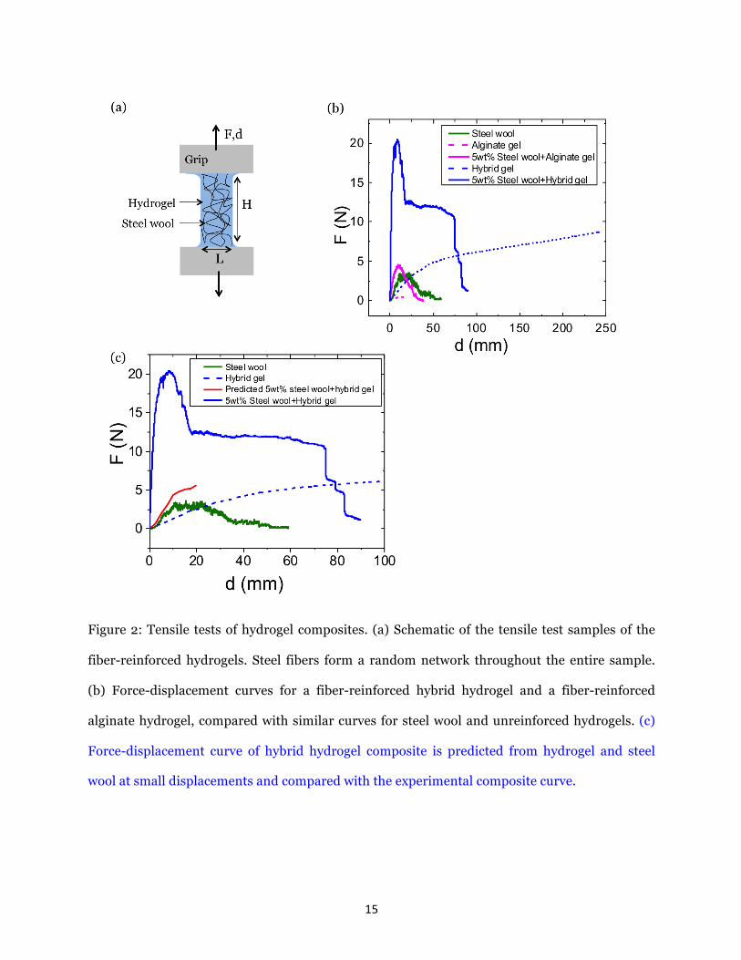
Figure 3 shows the deformation of the reinforced alginate gel during the tensile test in more
detail. As the load on the sample rises, the composite remains intact initially. When the load
reaches a maximum, which is comparable to the maximum load supported by just the steel
wool, the fibers start to disentangle, cutting through the alginate matrix in the process. The
schematic in figure 3(b) shows the molecular structure of the alginate chains with the Ca2+ ionic
crosslinks. Steel fibers can easily cut the alginate matrix, due to the poor mechanical behavior of
the matrix. This process continues with increased deformation until the fibers have completely
shredded the matrix at the point of failure.
The tensile response of the fiber-reinforced alginate-polyacrylamide hydrogel is illustrated in
detail in Figure 4. Initially, the fibers and matrix deform in concert. With continued
deformation, the fibers rotate toward the loading direction and the load rises quickly to a value
that is much larger than that predicted by the rule of mixtures applied to matrix and steel wool.
At this point, the interface between fibers and matrix starts to debond and the load decreases
until it reaches a plateau value characterized by continuous fiber sliding and pull out. During the

7
fiber sliding stage, the matrix undergoes extensive deformation, but remains intact; there is no
cutting by the fibers. Eventually the fiber network is ripped apart causing abrupt failure of the
sample. The schematic in figure 4(b) illustrates the molecular structure of the alginate-
polyacrylamide hydrogel, with MBAA crosslinks in the polyacrylamide network and Ca2+
crosslinks in the alginate network. These hybrid crosslinks make the matrix extremely tough and
prevent any fibers cutting through the matrix.
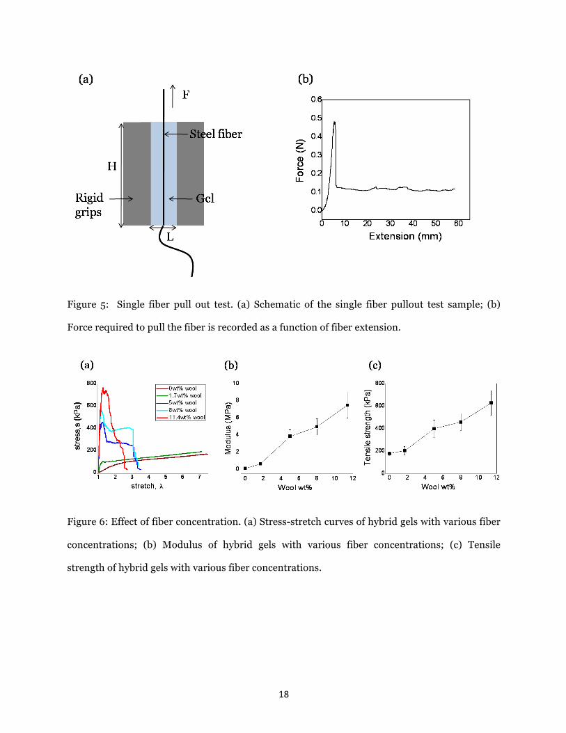
Because frictional sliding is an important aspect of the failure mechanism, single-fiber pullout
tests were performed to investigate the interfacial properties (Fig. 5(a)). Figure 5(b) shows a
typical force-displacement curve for a fiber pullout experiment. The curves go through a
maximum, which coincides with the failure of the interface between fiber and matrix. After
debonding, the fiber pulls out of the matrix at a constant frictional force of approximately
0.155 ± 0.052 N. In the experiments, the peak load was difficult to reproduce, but the magnitude
of the plateau force was very consistent. The average friction stress between fiber and matrix
was calculated by dividing the frictional force by the total interfacial area between fiber and
matrix, yielding a value of approximately 5kPa. This result was used to estimate the energy
dissipated by frictional sliding of the fibers. The total fiber length (6.78 m) was calculated from
the mass of the fibers embedded in a typical sample (0.3 g), the density of steel (7.8 g/cm3), and
the average cross-sectional area (80 µmx 70 µm) of the fibers. An upper bound for the energy
dissipated in friction during the tensile test, can be found by multiplying the frictional force with
the total fiber length, yielding a value of approximately 1.06 ±0.35 J. The total energy dissipated
during the tensile test can be calculated from the force-displacement curve in figure 2(b),
resulting in a value of 1.02 J. Part of this energy is dissipated in the deformation of the hydrogel
matrix and this part can be estimated from the force-displacement curve of the hydrogel to yield
0.30 J. Thus the energy dissipated by fiber sliding is approximately 0.72 J, which compares
favorably with the upper bound – approximately 70% of the total energy dissipation during the
tensile test is associated with frictional losses.

8
Figures 6(a) through (c) illustrate the effect of the volume fraction of the steel wool on the
mechanical response of the composites. The nominal stress was obtained by dividing the force
by the initial cross-sectional area of the sample; stretch was calculated by dividing the length of
the deformed sample by its initial value. The tensile strength was defined as the maximum
nominal stress supported by the composites. The elastic modulus was calculated from the slope
of the stress-strain curves up t0 5% strain. The fiber concentration was varied from 0 to
11.4 wt%. Without fiber reinforcement, the hybrid gel has a very large stretch to failure, but low
stiffness and strength. Introducing the fibers reduces the stretchability of the gel, but increases
the modulus and strength significantly. Evidently the weight fraction of the steel wool has a
large effect on the stress-stretch curves: At low weight fraction, the response of the composite is
dominated by the hydrogel and the stress-stretch curve is similar to that of a pure hydrogel. As
the weight fraction is increased, the shape of the curve is altered and it develops a distinct peak
followed by a plateau, associated with fiber debonding and sliding, respectively. At even higher
weight fractions, the steel wool completely dominates the response, the plateau disappears, and
the stress-stretch curve becomes similar to that of steel wool.
Synthesis of fiber-reinforced composites involves a large number of variables, including the
nature of the fibers, the fiber architecture, and the properties of the fiber/matrix interface. As a
result of this diversity, composites with very distinct attributes can be fabricated using the same
matrix material. For example, recently Lin et al [13] reinforced the same hydrogel with highly
aligned fibers of a stretchy thermoplastic polymer. As a result, their composites have very
different behavior: Our composites have a stress-strain behavior where the stress first peaks and
then drops to a plateau of constant stress. This makes it possible to tailor the stress at which
energy dissipation occurs. This behavior is distinctly different from the behavior reported by Lin
et al, where no plateau was observed. In our composites, fiber sliding is an important aspect of
the failure mechanism and frictional losses represent a significant fraction of the energy
dissipated during failure. In Lin’s composites, energy is dissipated mainly as a result of fiber

9
fracture. The random-fiber composites can sustain much higher stresses than predicted based
on the rule of mixtures for the individual components, i.e., there is a strong synergistic effect
between the steel wool and the matrix material. The stress-strain curves of the composites
reported by Lin et al, in contrast, follow the rule of mixtures. Our results suggest that fiber-
reinforced tough hydrogels may be useful in applications that require toughness, strength and
stiffness – examples include materials for energy absorption, materials for tendon repair
surgery, flexible electronics and sensors. The distinct stress-stretch behavior of our composites
are ideal to use as energy absorbing materials, for instance, to soften the effect of an impact on a
helmet [24]. Although the total energy dissipated by the composite is similar to the energy
absorbed by the tough hydrogel when stretched to rupture, the level of stress during the
deformation can be tailored by changing the fiber concentration, a distinct advantage over the
unreinforced hydrogel. When designing an energy absorbing material for helmets, the material
should absorb as much energy as possible, while limiting the maximum stress to the head to
approximately 0.9 MPa to prevent injury [24,25]. The hydrogel composites have high energy
absorption and a plateau stress that can be tailored to not exceed the maximum allowable value.
For example, a 5 wt% composite has an energy absorption of approximately 0.6 MJ/m3 and a
plateau stress of 0.3 MPa; an 8 wt% composite has an energy absorption of 0.9 MJ/m3 and a
plateau stress of 0.4 MPa. These values compare favorably with commonly used energy
absorbing materials such as expanded polystyrene, which has an energy absorption of
0.8 MJ/m3 and a maximum stress in the range of 0.7-0.9 MPa.
Another possible application of hydrogel composites would be in tendon repair surgery, where
reinforcing patches are used to help torn tendons heal. Current reinforcing patches are made
from materials including porcine dermis, porcine intestine submucosa, or porous
polyurethaneurea (Artelon®). Current tendon repair patches have an initial stiffness comparable
to our composites and a higher stiffness at large strains. Despite advances in surgical
techniques, the structural failure rate of these patches can be very high. Failure has been

10
attributed to sutures cutting through the reinforcing patches [26], which should not be an issue
for the tough hydrogel. A fiber-reinforced tough hydrogel may serve as a potential reinforcement
patch for suturing, although different biocompatible reinforcing fibers would need to be used.
Finally, one can also envision applications where electronics and living tissue are coupled using
flexible and stretchable devices [27-30], an area that has gained much interest recently. These
devices are used to probe the electrical activity near the surfaces of the heart, brain, or skin.
Recent work includes embedding a 3D network of silicon nanowires with electronic circuitry
into a soft gel matrix [31]. By integrating electrical sensors within the 3D scaffolds, cellular
activities and physicochemical changes can be monitored. One can envision a similar approach
to probe cells in a beating heart or to instill a sense of touch in a soft robotic hand. When
electronics and biological tissues are coupled with flexible and stretchable devices, these devices
need to be matched to the mechanical properties of the biological tissues. The hydrogel
composites have stiffness values up to 10 MPa. By comparison, cartilage has a stiffness in the
range of 6-15 MPa, while skin has a stiffness of 1-3 MPa [32]. The properties of the hydrogel
composite can be optimized to the specific application by selecting the appropriate fiber
material, orientation distribution, and volume fraction
4. Conclusion
We have used brittle and tough hydrogel matrices to prepare random fiber-reinforced
composites. Composites that have a brittle matrix such as an alginate hydrogel fail by fibers
cutting through the matrix. Composites based on tough alginate-polyacrylamide hybrid
hydrogels, on the other hand, fail by debonding and sliding of the fibers, dissipating a significant
amount of energy in the process. They can carry significantly more load than either matrix or
the random fiber network. The combination of high strength, stiffness, and toughness, and the
ability of sustaining large strains, along with easy method of synthesis, makes fiber-reinforced
tough hydrogel composites good candidates for a range of applications.

11
Acknowledgement
This work was supported by the MRSEC (DMR-0820484) at Harvard University and by the
National Science Foundation through grant CMMI-1404653. The authors are grateful to Prof.
David J. Mooney for providing the Instron machine used in the mechanical testing.

12
References
[1] K.Y. Lee&D.J. Mooney, Hydrogels for tissue engineering, Chem Rev., 101, 2001, 1869-1879
[2] R. Langer,Drug delivery and targeting, Nature, 392, 1998, 5-10
[3] D.J. Beebe, J.S. Moore, J.M. Bauer, Q. Yu, R.H. Liu, C. Devadoss & B. Jo, Functional hydrogel
structures for autonomous flow control inside microfluidic channels, Nature, 404, 2000, 588-590
[4] P. Calvert, Hydrogels for Soft Machines, Adv Mater, 2009, 21, 743-756
[5] J.P. Gong, Why are double network hydrogels so tough, Soft Matter, 6, 2012, 2583-2590
[6] X.Zhao, Multi-scale multi-mechanism design of tough hydrogels: building dissipation into stretchy
network, Soft Matter, 2014, 10, 672-687
[7] R.F.Ker, The design of soft collagenous load-bearing tissues, J. Exp. Biol., 1999, 202, 3315-3324
[8] P.Calvert, Hydrogels for soft machines, Adv. Mater., 21, 2009, 743-756
[9] C.-D.Young, J.-R.Wu, T.-L.Tsou, High-strength, ultra-thin and fiber-reinforced pHEMA artificial
skin, Biomaterials, 19, 1998, 1745-1752
[10] F.T.Moutos, L.E.Freed, F.Guilak, A biomimetic three-dimensional woven composite scaffold for
functional tissue engineering of cartilage, Nature materials, 6, 2007, 162-167
[11] A.Agrawal, N.Rahbar, P.D.Calvert, Strong fiber-reinforced hydrogel, Acta Biomateriala, 9, 2013,
5313-5318
[12] I-C. Liao, F.T. Moutos , B.T. Estes , X. Zhao and F. Guilak, Composite three-dimensional woven
scaffolds with interpenetrating network hydrogels to create functional synthetic articular cartilage,
Adv. Funct. Mater., 2013, 23, 5833-5839
[13] S.Lin, C.Cao, Q.Wang, M.Gonzalez, J.E. Dolbow, X.Zhao, Design of stiff, tough and stretchy
hydrogel composites via nanoscale hybrid crosslinking and macroscale fiber reinforcement, Soft
Matter, 2014, 10, 7519-7527
[14] S.N.Bakarich, R.Gorkin III, M. Panhuis, G.M.Spinks, Three-dimensional printing fiber reinforced
hydrogel composites, 2014, 6, 15998-16006
[15] J.P. Gong, Y. Katsuyama, T. Kurokawa &Y. Osada, Double-network hydrogels with extremely high
mechanical strength, Adv Mater, 15, 2003, 1155-1158
[16] K. Haraguchi &T. Takehisa, Nanocomposite hydrogels: A unique organic-inorganic network
structure with extraordinary mechanical, optical, and swelling/de-swelling properties, Adv Mater,
14, 2002, 1120-1124
[17] T. Huang, H. Xu, K. Jiao, L. Zhu, H.R. Brown, &H. Wang, A novel hydrogel with high mechanical
strength: A macromolecular microsphere composite hydrogel, Adv Mater, 19, 2007, 1622-1626

13
[18] K.J. Henderson, T.C. Zhou, K.J. Otim &K.R. Shull, Ionically Cross-Linked Triblock Copolymer
Hydrogels with High Strength. Macromolecules, 43, 2010, 6193-6201
[19] J.-Y. Sun, X.H.Zhao, W.R.K.Illeperuma, O.Chaudhuri, K.H.Oh, D.J.Mooney, J.J.Vlassak, Z.Suo,
Highly stretchable and tough hydrogels, Nature, 489, 2012, 133-136
[20] C.Gamonpilas, M.N.Charalambides, J.G.Williams, Determination of large deformation and fracture
behavior of starch gels from conventional and wire cutting experiments, J.MaterSci, 44, 2009,
4976-4986
[21] F.Baldi, F.Bibnotti, I.Peroni, S.Agnelli, T.Ricco, On the measurement of the fracture resistance of
polyacrylamide hydrogels by wire cutting test, Polymer testing, 31, 2012, 455-465
[22] A.Bentur and R.Cree, Cement reinforced with steel wool, Int. J. Cem. Comp. & L Concr., 9, 1987,
217-223
[23] L.Li, D.D.L.Chung, Electrical and mechanical properties of electrically conductive polyethersulfone
composites, Composites, 35, 1992, 215-223
[24] N.J.Mills & A.Gilchrist , The Effectiveness of Foams in Bicycle and Motorcycle Helmets, Accid. Anal.
and Preview, 23, 1991, 153-163
[25] http://www.grantadesign.com/resources/materials/casestudies/helmet.htm
[26] S.Chaudhury, C.Holland, M.S.Thompson, F.Vollrath, A.J.Carr, Tensile and shear mechanical
properties of rotator cuff repair patches, J. Shoulder Elbow Surg., 2012, 21, 1168-1176
[27] B.P.Timko et al., Electrical recording from hearts with flexible nanowire device arrays. Nano Lett.,
9, 2009, 914–918
[28] J.Viventi et al., Flexible, foldable, actively multiplexed, high-density electrode array for mapping
brain activity in vivo. Nature Neurosci., 14, 2011, 1599–1605
[29] D-H.Kim et al., Epidermal electronics. Science, 333, 2011, 838–843
[30] N.Lu, C.Lu, S.Yang, J.Rogers, Highly sensitive skin-mountable strain gauges based entirely on
elastomers, Adv. Funct. Mater., 2012, 22, 4044-4050
[31] B.Tian, J.Liu, T.Dvir, L.Jin, J.H.Tsui, Q.Qing, Z.Suo, R.Langer, D.S.Kohane, C.M.Lieber,
Macroporous nanowire nanoelectronic scaffolds for synthetic tissues, Nat. Mater.,2012, 11, 986–
994
[32] M.F.Ashby, The CES EduPack database of natural and man-made materials, 2008, Cambridge, UK:
Granta Design

14
Figure 1: Wire cutting tests for a brittle (a, b) and a tough hydrogel (c, d). (a) Alginate hydrogel
being cut by a steel wire. (b) The cut sample is turned 900 and the two pieces are separated to
show the cut. (c) Alginate-Polyacrylamide hybrid hydrogel deforms, but resists cutting. (d) The
sample recovers its original shape when the wire is removed.
15
Figure 2: Tensile tests of hydrogel composites. (a) Schematic of the tensile test samples of the
fiber-reinforced hydrogels. Steel fibers form a random network throughout the entire sample.
(b) Force-displacement curves for a fiber-reinforced hybrid hydrogel and a fiber-reinforced
alginate hydrogel, compared with similar curves for steel wool and unreinforced hydrogels. (c)
Force-displacement curve of hybrid hydrogel composite is predicted from hydrogel and steel
wool at small displacements and compared with the experimental composite curve.
16
Figure 3: Failure mechanism of a brittle and weak alginate hydrogel composite. (a) Force-
displacement curve of an alginate hydrogel composite. (b) Schematic of alginate hydrogel. (c)
Photos at two stages during the tensile test. At small deformations (point X), the fibers are
bonded to the matrix. After reaching a maximum force, the composite starts to fail by fibers
cutting through the matrix (point Y).

17
Figure 4: Failure mechanism of a tough hybrid hydrogel composite. (a) Force-displacement
curve of an alginate-polyacrylamide hydrogel composite. (b) Schematic of alginate-
polyacrylamide hydrogel. (c) Photos at two stages during the tensile test. At small displacements
(point X), the fibers are bonded to the matrix. Fiber debonding is observed near the peak force.
At larger displacements (point Y), the fibers slide through the matrix.
18
Figure 5: Single fiber pull out test. (a) Schematic of the single fiber pullout test sample; (b)
Force required to pull the fiber is recorded as a function of fiber extension.
Figure 6: Effect of fiber concentration. (a) Stress-stretch curves of hybrid gels with various fiber
concentrations; (b) Modulus of hybrid gels with various fiber concentrations; (c) Tensile
strength of hybrid gels with various fiber concentrations.