328 ieee journal on selected areas in …weiyu/relay_jsac.pdf · supported in part by nokia...
TRANSCRIPT

328 IEEE JOURNAL ON SELECTED AREAS IN COMMUNICATIONS, VOL. 25, NO. 2, FEBRUARY 2007
Joint Optimization of Relay Strategies and ResourceAllocations in Cooperative Cellular Networks
Truman Chiu-Yam Ng and Wei Yu, Member, IEEE
Abstract— This paper considers a wireless cooperative cellulardata network with a base station and many subscribers inwhich the subscribers have the ability to relay information foreach other to improve the overall network performance. For awireless network operating in a frequency-selective slow-fadingenvironment, the choices of relay node, relay strategy, and theallocation of power and bandwidth for each user are importantdesign parameters. The design challenge is compounded furtherby the need to take user traffic demands into consideration. Thispaper proposes a centralized utility maximization framework forsuch a network. We show that for a cellular system employingorthogonal frequency-division multiple-access (OFDMA), theoptimization of physical-layer transmission strategies can be doneefficiently by introducing a set of pricing variables as weightingfactors. The proposed solution incorporates both user trafficdemands and the physical channel realizations in a cross-layerdesign that not only allocates power and bandwidth optimallyfor each user, but also selects the best relay node and best relaystrategy (i.e. decode-and-forward vs. amplify-and-forward) foreach source-destination pair.
Index Terms— Cooperative communication, Lagrangian dual-ity theory, network utility maximization, orthogonal frequency-division multiplex (OFDM), relay channel, spectrum optimiza-tion, wireless cellular networks.
I. INTRODUCTION
IN a wireless network with many source-destination pairs,cooperative transmission by relay nodes has the potential
to improve the overall network performance. When a relay ora group of relays are physically located between the sourceand the destination, the relays may facilitate transmission byfirst decoding the transmitted codeword, then forwarding thedecoded codeword to the destination. This strategy is known asdecode-and-forward (DF). Alternatively, a relay may simplyamplify its received signal and employ a so-called amplify-and-forward (AF) strategy. In both cases, the use of relay hasbeen shown to improve the overall transmission rate [1] and/orthe diversity [2]–[7] of the wireless network.
This paper is motivated by the following questions: Ina cooperative wireless network, which node should act asa relay? What relay strategy should be used? When, andin which frequency should relaying be employed? Clearly,the answers to these questions depend on the topology ofthe network. For example, consider a single-relay channel
Manuscript received February 8, 2006; revised June 30, 2006. This workhas been presented in part at 40th Annual Conference on Information Sciencesand Systems (CISS), Princeton, NJ, USA, March 2006. This work wassupported in part by Nokia Research Center and in part by the Nature Scienceand Engineering Research Council (NSERC) of Canada.
The authors are with The Edward S. Rogers Sr. Department of Electricaland Computer Engineering, University of Toronto, Toronto, Ontario M5S 3G4,Canada (email: [email protected], [email protected]).
Digital Object Identifier 10.1109/JSAC.2007.070209.
Source Destination
Relay
Fig. 1. A single-relay channel.
as shown in Fig. 1. When a relay is located closer to thesource than to the destination, DF appears to be a naturalchoice. On the other hand, when the relay is located closer tothe destination, its received signal-to-noise ratio (SNR) maynot be high enough to allow decoding, in which case AFis more suited. However, the optimal operation of relays ismore complicated than that provided by a rule-of-thumb. Thisis because the choices of relay node and relay strategy alsodepend on the amount of transmit power available at the sourceand at the relay, and further on the user traffic patterns. Thisis particularly true in a power- and bandwidth-limited networkin which each node may act as a source/destination or relaysimultaneously. In this case, the partitioning of the power andbandwidth between the transmission of one’s own data vs. therelaying of other users’ traffic becomes crucial. The optimalpower and bandwidth allocation is further coupled with thechoice of relay and the choice of relay strategies.
This paper takes a system view of the cooperative network,and aims to jointly optimize relay strategies and physical-layerresources in a network. The focus of this work is on a cellulardata network with a single base station and many subscribersin each cell, where each subscriber has the ability to relayinformation for each other. This is called a multihop cellularnetwork with peer-to-peer relaying [8]–[11]. However, theterm multi-hop cellular usually refers to networks in which therelays simply route traffic from node to node. In this paper, weconsider cooperative networks that use physical-layer relayingstrategies, which take advantage of the broadcast nature ofwireless channel, and allow the destination to cooperatively“combine” signals sent by both the source and the relay.
The target application of this paper is a fixed broadbandaccess network in which the wireless channels are relativelystationary and channel estimations are feasible, and wherecentralized power control and bandwidth partitioning can beimplemented. The use of cooperative strategies in a cellu-lar network has many perceived benefits, e.g., throughputincrease, coverage extension, power saving, and interferencemitigation, etc. This paper presents an optimization frameworkto quantify some of these benefits.
In a cellular data network, bidirectional upstream and down-stream transmissions are maintained for each subscriber. In a
0733-8716/07/$25.00 c© 2007 IEEE

NG and YU: JOINT OPTIMIZATION OF RELAY STRATEGIES AND RESOURCE ALLOCATIONS 329
traditional system with power control, subscribers closer tothe base station transmit at a lower power level so they do notcause excess interference to other users. The users at the edgeof the cell transmit at its maximum power limit. The mainidea of a cooperative cellular network is to take advantage ofthe extra power available at users close to the base stationby allowing them to act as a relay for users at the edge ofthe cell. The objective of this paper is to provide an efficientprocedure for a joint optimization of the choice of relay andthe choice of relay strategy for each transmission pair, and theallocation of power and bandwidth for each transmitting nodein the network. The rest of this section contains a literaturesurvey and highlights the main contributions of this paper.
A. Related Work
Many well-known relay strategies can trace their rootsto the information-theoretical study of the relay channel byCover and El Gamal [12]. Cover and El Gamal showedthat the capacity of a degraded relay channel is achieved bya block-Markov scheme with an infinite number of blocksand a decode-and-forward strategy at the relay. They furtherproposed a quantize-and-forward strategy for general relaychannels. Amplify-and-forward can be interpreted as an analogcounterpart to quantize-and-forward. Depending on the chan-nel condition and performance criterion, DF may outperformAF, or vice versa [13]–[15].
In practical systems, the restriction that the relay node maynot transmit and receive at the same time in the same fre-quency band is often imposed, giving rise to a so-called cheaprelay channel [16], [17]. Moreover, the block-Markov schemeis often simplified into a two-time-slot strategy. These simpli-fications, although strictly suboptimal from an information-theoretical perspective, nevertheless make relay operationsmuch easier to implement. The rest of the paper focuses ontwo-time-slot implementations of DF and AF strategies forcheap relay nodes [1], [18].
This paper envisions a type of relay-assisted network calledcooperative network where user nodes act as relays for one an-other. We further assume that the cooperative network employsorthogonal frequency-division multiple-access (OFDMA), sothat each user node may simultaneously act as a source, adestination, or as a relay, but at different frequency tones. Forfrequency-selective fading channels, power allocation amongtransmitting nodes and across frequency tones can greatlyaffect network performance. (The same channel model isalso applicable to frequency-flat fading channels with adap-tive modulations across fading states.) The issue of powercontrol for relay-assisted networks has been dealt with innumerous studies in the literature. These studies all pointto the importance of power allocation and they differ inperformance criteria (rates [19] vs. probabilities of outage orerror [20]), power constraints (separate- [21] vs. joint- [22]power constraints between the source and the relay), powercontrol schemes (centralized [23] vs. distributed [24]), andsystem setups (single- [25] vs. multi-stage-relay [26], single-vs. multi-parallel-relay [27], three-terminal single-relay [28]vs. multi-nodes (ad-hoc, cellular) [29]). Along with powerallocation, some studies listed above (e.g. [20], [27]) alsojointly consider relay-node selection.
Besides power allocation and relay operations, bandwidthallocations for transmission nodes are equally important. Notethat in some relay channel literature such as [19], [23],[30]–[33], bandwidth allocations refer to the assignments oforthogonal frequencies for transmissions of the source and therelay(s). However, this is not the type of bandwidth allocationthat is investigated here. In this paper, each frequency toneis occupied by only one source-destination pair (with thepossibility of relay participation), and both the source andthe relay always transmit in the same frequency tone. Thus,bandwidth allocations in this paper refer to the assignmentsof source-destination pair to each frequency tone.
Despite the rich literature on relay-assisted networks, tothe best of our knowledge, none of the previous work dealswith the joint optimization of relay selection, relay-strategyselection, power and bandwidth allocation in a cooperativenetwork employing physical-layer relaying strategies. This isin part due to the fact that such an optimization problem looksformidable at a first glance as so many different combinationsof resource allocations and relay operations are possible. Inaddition, as the joint optimal scheme should also account forusers’ traffic demands, the optimization problem representsa cross-layer design. The main contribution of this paper isthat the seemingly difficult joint optimization problem canbe solved globally and efficiently within a network utilitymaximization framework. A key technique in this study is theuse of pricing to determine the optimal relay strategies. Pricinghas been used in earlier studies of both multi-hop hotspotnetwork [34] and ad-hoc relay network [35], where prices areused to give user nodes an incentive to relay. However, in thispaper, we introduce a centralized optimization framework, inwhich the network has control over the behavior of the usernodes. Therefore, the pricing variables in this paper only serveas weighting factors in the regulation of system resources.
B. Summary of Contribution
This paper proposes a centralized optimization frameworkfor the maximization of total system utility. The target systemis a cooperative cellular network where subscribers act asrelays for one another using physical-layer relaying strategies(e.g. DF, AF). The physical layer uses OFDM so that bothpower and bandwidth may be freely allocated among all nodes(but with the restriction that in each frequency tone, only oneset of source and destination, plus possibly a relay, may beactive). The main contributions of the paper are as follows:
• We show that the cross-layer problem may be decom-posed into two subproblems: a utility maximization prob-lem in the application layer and a joint relay-strategyand relay-node selection and power- and bandwidth-allocation problem in the physical layer. A set of dualvariables coordinates the application-layer demand andphysical-layer supply of rates.
• We further show that the physical-layer joint relay-strategy and relay-node selection and resource allocationproblem may be solved globally and efficiently usinganother set of dual variables that accounts for the costof power expended at each node.
• Together, these two dual decomposition steps solve theoverall utility maximization problem globally with a

330 IEEE JOURNAL ON SELECTED AREAS IN COMMUNICATIONS, VOL. 25, NO. 2, FEBRUARY 2007
complexity that is linear in the number of frequency tonesand the number of relay strategies, and quadratic in thenumber of relays.
C. Outline of the Paper
The remainder of the paper is organized as follows. InSection II, we present a utility maximization framework forthe joint resource allocation and relay-strategy and relay-node selection problem. We show that the overall cross-layerproblem can be decomposed into two subproblems. SectionIII answers the question of which relay strategy is optimal foreach source-destination, while taking both power constraintsand users’ traffic demands into consideration. Section IV con-tains simulation results that quantify the merit of relaying andillustrate the allocations of resource and operations of relaysin an optimized cooperative network. Finally, conclusions aredrawn in Section V.
D. Notation
Boldface lower-case letters are used for column vectors.Vectors 0 and 1 denote the all-zero and all-one column vectorsrespectively. For two vectors of the same length, “�” and “�”are used to denote component-wise inequalities. Lower-caseletter xi denotes the ith entry of vector x. Boldface upper-caseletters are used to denote matrices. For a matrix X , X(i, j)represents the entry on the ith row and the jth column. X(i, :)denotes the ith row of X , and X(:, j) denotes the jth columnof X . The superscripts T , H , and ∗ denote the transpose, theHermitian, and the optimal value of the variable respectively.
II. OPTIMIZATION USING PHYSICAL-LAYER RELAYING
This paper focuses on physical-layer relaying strategieswhere the source and the relay transmit in the same frequency,but in two different time-slots. Physical-layer relaying makesuse of the broadcast nature of wireless channels, so that ateach frequency tone, the destination receives and processesdata sent by the source and the relay in both time-slots. BothDF and AF strategies are considered.
A. Utility Maximization Framework
This paper adopts a utility maximization framework inwhich each data stream has an associated utility function, andthe objective is to maximize the sum utility in the network.This network utility maximization framework is originatedfrom the work of Kelly [36], and has been recently applied tomany physical-layer design problems (e.g. [37], [38]). A utilityfunction is a concave and increasing function of data ratesthat reflects user satisfaction. The choice of utility functiondepends on the underlying application (e.g. data, voice, video).By maximizing the sum utility, a network operator maintainsa balance between competing resource demands by differentusers in a network. This paper assumes that the base stationdictates when and how the user nodes may cooperate, whichis realistic in a cellular environment with centralized control.
The cooperative cellular network of interest is shown in Fig.2. The network consists of a base station and K user nodes,all of which are equipped with a single antenna. Let K =
User 2
User K
User 1
Base Station(Node K + 1)
Fig. 2. A cooperative cellular network with a base station and K users.
{1, 2, ..., K} be the set of user nodes. Denote the base stationas node K + 1. Let K+ = {1, 2, ..., K + 1} be the extendedset of nodes. Each of the K user nodes has both downstreamand upstream communications with the base station. Let (s, d)be a source-destination pair, or data stream. Then, the set ofall data streams M is {(1, K + 1), (2, K + 1), ..., (K, K +1), (K + 1, 1), (K + 1, 2), ..., (K + 1, K)}. The cardinality ofM is 2K .
We assume that the cooperative network employs anOFDMA physical-layer with N tones. Let N = {1, ..., N}denote the set of tones. We further assume that the OFDMframes are synchronized throughout the network, so thatcooperative transmission takes place in a tone-by-tone basis,and transmissions in different frequency tones do not interferewith each other. The wireless channel is modelled as afrequency-selective fading channel with coherence bandwidthin the order of the bandwidth of a few tones. This impliesthat fading between tones far away from each other is un-correlated. We assume that the network operates in a slowfading environment, so that channel estimation is possible andfull channel side-information (CSI) is available at the basestation. Although this paper focuses on a frequency-selectiveenvironment employing OFDMA, with suitable modifications,the optimization framework is also applicable to a frequency-flat fading environment if rate adaptation across fading statesis possible.
To prevent inter-stream interference, the restriction thatonly one data stream can be active in each tone is imposed.However, each of the 2K data streams can use more thanone frequency tones. We also impose the restriction thatthe active stream in each tone can use at most one relay(where the relay node can be any one of the other K − 1user nodes). Moreover, the source-relay, source-destination,and relay-destination links all use the same frequency tone1.Note that upstream and downstream transmissions take placesimultaneously in the network, so that the base station is botha source and a destination (but in different tones). However,the base station can never be a relay. On the other hand, alluser nodes in the network can simultaneously be a source, arelay, and a destination (again in different tones).
The main challenge in designing such a network is toallocate power and bandwidth optimally across all frequency
1The generalization of this setup to the case where source-relay andrelay-destination communications may occur in different tones is nontrivial.Computational complexity of the optimization increases considerably.

NG and YU: JOINT OPTIMIZATION OF RELAY STRATEGIES AND RESOURCE ALLOCATIONS 331
tones and across all nodes. Let P be a (K + 1) × N matrixsuch that P (i, n) denotes the power expended by node i intone n (i ∈ K+, n ∈ N ). Because only one data stream isactive in each tone and only the source and the relay maytransmit, the column vector P (:, n) (n ∈ N ) has at mosttwo non-zero entries. Similarly, let R be a 2K × N matrixwith R(m, n) denoting the data rate of stream m in tone n(m ∈ M, n ∈ N ). Since only one stream can be active ineach tone, the column vector R(:, n) (n ∈ N ) has at most onenon-zero entry. Power and rate are related by the achievablerate region, denoted as R ∈ C(P ). The achievable rate regionis the set of all possible rates achievable at a given powerlevel. It implicitly accounts for the best possible use of relaystrategies.
By definition, (P1)i (i ∈ K+), i.e. the row sum of P ,is the total power expended at node i, summing across alltones. For practical purposes, each node has a separate powerconstraint. Let pmax = [pmax
1 , pmax2 , ..., pmax
K+1]T , where pmax
i
is the individual power constraint for node i. Similarly, (R1)m
(m ∈ M), i.e. the row sum of R, gives the total data rate ofstream m, summing across all tones.
Let Um be the utility function of data stream m, where Um
is a function of achievable rate of stream m, i.e. (R1)m. Theobjective of the optimization problem is to optimally choosethe active data stream and allocate power in each tone, whileat the same time selecting the best relay node and the bestrelay strategy, in order to maximize the network sum utility.Expressed succinctly, the optimization problem is
maxP,R
∑m∈M
Um((R1)m) (1)
s.t. P1 � pmax, R ∈ C(P )
As mentioned earlier, this paper assumes a slow-fadingenvironment with full CSI in which adaptive power- andbit-loading may be implemented in a centralized fashion. Ina practical system, channel estimation needs to be done atthe receivers and fedback to the base station, which thenmust solve the above optimization problem and inform allusers the appropriate power levels and cooperative strategies.When the wireless fading channel has both fast-fading andslow-fading components, optimization may also be done in astatistical sense by adapting power allocation to the averageSNR (or the slow-fading component of the channel). Onlineimplementation may be further simplified by constructing alook-up table that maps the channel gains to the optimalcooperative strategies.
B. Cross-layer Optimization via Dual Decomposition
Finding the optimal solution of (1) involves a search over allpossible power and bandwidth allocations and over all possiblerelays and relay strategies. So, the optimization problem (1)is a mixed integer programming problem. However, in anOFDMA system with many narrow subcarriers, the optimalsolution of (1) is always a convex function of pmax, becausethe time-sharing of two transmission strategies can alwaysbe implemented via frequency-division multiplexing acrossfrequency tones. The idea is that if two sets of rates usingtwo different resource allocations and relay strategies are
achievable individually, then their linear combination is alsoachievable by a frequency-division multiplex of the two sets ofstrategies. This is possible when the coherence bandwidth islarger than the width of a few tones, so that adjacent tones havesimilar channel conditions, and time-sharing can be achievedin the frequency domain. The idea of getting convexity throughfrequency-sharing is discussed earlier in [39] for a spectrumbalancing problem. In particular, using the duality theory of[39], the following is true:
Proposition 1: The optimization problem (1) has zero du-ality gap in the limit as the number of OFDM tones goes toinfinity. This is true even as discrete selections of data stream,relay, relaying strategy, and bit rate are involved.
The paragraph leading to the proposition contains the mainidea of the proof. A detailed proof can be constructed along aline of argument as in [39]. The zero-duality-gap result opensthe door for using convex optimization techniques for solvingthe utility maximization problem (1). The rest of this sectiondevelops a Lagrangian dual decomposition approach to solve(1).
First, introduce a new variable t = [t(1,K+1), t(2,K+1), ...,
t(K,K+1), t(K+1,1), t(K+1,2), ..., t(K+1,K)]T , and rewrite (1)
as
maxP,R,t
∑m∈M
Um(tm) (2)
s.t. P1 � pmax, R1 � t, R ∈ C(P ).
Because Um is an increasing function, when the objectiveof (2) is maximized, t must be equal to R1. Therefore,(1) and (2) must have the same solution. The key step indual decomposition is to relax the constraint R1 � t. TheLagrangian becomes
L(P , R, t, λ) =∑
m∈MUm(tm) + λT
(R1 − t
)
=∑
m∈M
(Um(tm) + λm
( ∑n∈N
R(m, n) − tm
)), (3)
where λ = [λ(1,K+1), λ(2,K+1), ..., λ(K,K+1), λ(K+1,1),
λ(K+1,2), ..., λ(K+1,K)]T , with each element λm (m ∈ M)
being a dual variable corresponding to stream m. Observethat the dual function
g(λ) =
{maxP ,R,t
L(P , R, t, λ)
s.t. P1 � pmax, R ∈ C(P )(4)
consists of two sets of variables: application-layer variable t,and physical-layer variables P and R. Moreover, g(λ) can beseparated into two maximization subproblems, namely a utilitymaximization problem, corresponding to a rate adaptationproblem in the application layer,
gappl(λ) = maxt
∑m∈M
(Um(tm) − λmtm
), (5)
and a joint relay-strategy and relay-node selection and powerand bandwidth allocation problem in the physical layer,
gphy(λ) =
⎧⎨⎩
maxP ,R
∑m∈M
λm
∑n∈N
R(m, n)
s.t. P1 � pmax, R ∈ C(P ). (6)
332 IEEE JOURNAL ON SELECTED AREAS IN COMMUNICATIONS, VOL. 25, NO. 2, FEBRUARY 2007
The optimization framework provides a layered approach tothe sum utility maximization problem. The interaction betweenthe layers is controlled through the use of the dual variableλ as a set of weighting factors, which centrally coordinatesthe application-layer demand and physical-layer supply ofrates. The dual variable λ has a pricing interpretation: λm
(m ∈ M) represents dollars per unit of bit rate. As a supplierof data rates, the physical layer attempts to maximize thetotal revenues by adaptively allocating power and bandwidthand selecting the best choice of relay and relaying scheme ineach tone. A higher value of λm induces the physical layerto allocate more resources to the corresponding data stream.As a consumer of data rates, the application layer aims tomaximize the sum utility discounted by the total cost of datarates. A higher value of λm indicates that the cost of ratefor the corresponding data stream is high, thus inducing theapplication layer to lower traffic demand. Finally, because thesum utility maximization problem (2) has zero duality gap, itcan be solved by minimizing the dual objective:
minimize g(λ) (7)
subject to λ � 0
One way to solve this dual problem is to update λ using asubgradient method [40] as follows:
Subroutine 1: Subgradient-based method for solving (7)
1) Initialize λ(0).2) Given λ(l), solve the two subproblems (5) and (6)
separately to obtain the optimal values t∗, P ∗, and R∗.3) Perform a subgradient update for λ:
λ(l+1) =[λ(l) + (ν(l))T (t∗ − R∗1)
]+(8)
4) Return to step 2 until convergence.The subgradient method above is guaranteed to converge tothe optimal dual variable, if the step sizes ν(l) are chosenfollowing a diminishing step size rule [41]. From the optimaldual variables, the optimal primal variables can then be foundeasily.
C. Solutions of individual subproblems
This section describes efficient methods to solve each ofthe two individual subproblems corresponding to the applica-tion layer and physical layer respectively. In particular, thephysical-layer joint relay-strategy and relay-node selectionand resource allocation problem can be solved efficientlyby introducing another set of pricing variables that accountsfor the cost of power. This second decomposition at thephysical layer, together with the first decomposition describedin the previous section, solves the overall utility maximizationproblem globally and efficiently.
1) Application Layer Subproblem: Finding the optimalsolution of gappl(λ) as described in (5) is relatively easy. Notethat (5) can be solved by maximizing each of the summationterms separately. This means that the system searches forthe optimal user traffic demand t∗m independently for eachstream m, balancing the stream’s utility with the cost ofrate. Specifically, since Um is a concave function of tm,(Um(tm) − λmtm) is also a concave function of tm (m ∈
0 50 100 150 200 250 300 3500123456789
10
Target Rate (t), in Mbps
Util
ity
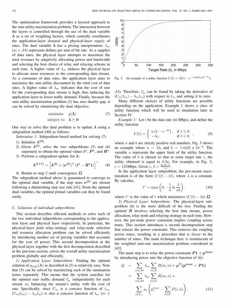
Fig. 3. An example of a utility function U(t) = 10(1− e−1.8421x10⁻⁸t).
M). Therefore, t∗m can be found by taking the derivative of(Um(tm) − λmtm) with respect to tm and setting it to zero.
Many different choices of utility functions are possibledepending on the application. Example 1 shows a class ofutility function which will be used in simulation later inSection IV.
Example 1: Let t be the data rate (in Mbps), and define theutility function
U(t) ={
a(1 − e−bt
), if t ≥ 0
−∞, if t < 0 , (9)
where a and b are strictly positive real numbers. Fig. 3 showsan example where a = 10, and b = 1.8421 x 10⁻⁸. Thevariable a represents the upper limit of the utility function.The value of b is chosen so that at some target rate c, theutility obtained is equal to 0.9a. For example, in Fig. 3,c = 125Mbps. Given c, b = ln (0.1)
−c .In the application layer subproblem, the per-stream maxi-
mization is of the form (U(t) − λt), where λ is a constant.By calculus,
t∗ = max(
0,−1b
lnλ
ab
), (10)
where t∗ is the value of t which maximizes (U(t) − λt).2) Physical Layer Subproblem: The physical-layer sub-
problem (6) is the more difficult of the two. Finding theoptimal R involves selecting the best data stream, powerallocation, relay node and relaying strategy in each tone. How-ever, the per-node power constraint implies coupling acrosstones. This section introduces a second decomposition stepthat relaxes the power constraint. This removes the couplingacross tones, resulting in a procedure that is linear in thenumber of tones. The main technique here is reminiscent ofthe weighted sum-rate maximization problem considered in[42].
The main step is to relax the power constraint P1 � pmax
by introducing prices into the objective function of (6):
Q =∑
m∈Mλm
∑n∈N
R(m, n) + µT (pmax − P1)
=∑
m∈Mλm
∑n∈N
R(m, n) +
∑i∈K+
µi
(pmax
i −∑n∈N
P (i, n)
), (11)
NG and YU: JOINT OPTIMIZATION OF RELAY STRATEGIES AND RESOURCE ALLOCATIONS 333
where µ = [µ1, µ2, ..., µK+1]T is a vector dual variable. The
key observation is that the dual function of the physical-layersubproblem
q(µ) =
{maxP ,R
Q(P , R, λ, µ)
s.t. R ∈ C(P )(12)
can now be decoupled into N per-tone maximization subprob-lems:
maxP (:,n),R(:,n)
∑m∈M
λmR(m, n) −∑
i∈K+
µiP (i, n)
s.t. R(:, n) ∈ C(P (:, n))(13)
In each tone, there is only one active stream. Further, only thesource S and relay R expend power. Therefore, an alternativeexpression of (13) is
max λmR(m, n) − (µSP (S, n) + µRP (R, n))s.t. R(:, n) ∈ C(P (:, n)), (14)
where the maximization is over m, choice of R, R(m, n),P (S, n), and P (R, n). The relaxation of P1 � pmax
removes the per-node power constraint. Hence, the per-toneproblem (14) is easier to solve than the original physical-layer subproblem. Moreover, the physical-layer subproblemis decoupled across tones. So, the computational complexitybecomes linear in the number of tones N . Again, using apricing interpretation, µi (i ∈ K+) represents dollars perunit of power at node i. A higher value of µi discouragesnode i from expending power, while a lower value of µi
does the opposite. Thus, the physical-layer subproblem tries tomaximize total revenue of data rates discounted by the cost ofpower. Together, λ and µ act as a set of weighting factors tocentrally determine the optimal resource allocations and relaystrategy at each tone.
A critical requirement for the decomposition of thephysical-layer subproblems into N per-tone subproblems isits convexity structure. Using the same argument as in SectionII-B, the physical-layer subproblem (6) can always be made aconvex function of pmax if time- or frequency-sharing can beimplemented. Therefore, the physical-layer subproblem alsohas zero duality gap, and it can be solved optimally via thedual problem
minimize q(µ) (15)
subject to µ � 0
Again, a subgradient approach with appropriate step sizes ε(l)
may be used to solve the dual problem. From the optimaldual variables, the optimal primal variables can then be foundrelatively easily.
Subroutine 2: Subgradient-based method for solving (15)
1) Initialize µ(0).2) Given µ(l), solve the N per-tone maximization prob-
lems (14) separately, then combine the results to obtainP ∗ and R∗.
3) Perform subgradient updates for µ:
µ(l+1) =[µ(l) + (ε(l))T (P ∗1 − pmax)
]+(16)
4) Return to step 2 until convergence.
D. Overview of the Algorithm
The two subroutines presented in this section are intercon-nected hierarchically. The overall sum utility maximizationproblem (2) can be solved optimally in the dual domain usingSubroutine 1. Step 2 of Subroutine 1 requires the solutions toboth the application-layer subproblem (which is trivial) andthe physical-layer subproblem (which requires Subroutine 2).Subroutines 1 and 2 use two nested subgradient update loopsto search for the optimal dual variable. Because the overalloptimization problem has zero duality gap, the followingtheorem holds:
Theorem 1: The algorithm summarized in the precedingparagraph always converges, and it converges to the globaloptimal value of the utility maximization problem (2). This istrue whenever the time-sharing property holds, which is thecase in the limit as the number of OFDM tones goes to infinity.
Computational experience suggests that the complexity ofsubgradient updates is polynomial in the dimension of the dualproblem, (which is K for g(λ) and 2K for q(µ)). Since thesubroutines are connected hierarchically, the complexity of allsubgradient updates of the proposed algorithm is polynomialin K .
III. OPTIMAL RELAY STRATEGY SELECTION
The previous section shows that in a cooperative cellularnetwork employing OFDMA with per-node power constraints,the physical-layer subproblem (6) can be solved globally andefficiently in the dual domain. However, this hinges uponefficient solutions to the per-tone problem (14), which isrequired in Step 2 of Subroutine 2. For each tone n (n ∈ N )the per-tone problem is a maximization of λmR(m, n) −µSP (S, n) − µRP (R, n), where λm, µS and µR are fixeddual variables. The goal of this section is to show that thisper-tone maximization problem can be solved efficiently viaan exhaustive search.
The main idea is to consider R(m, n) as the optimizingvariable and to express P (S, n) and P (R, n) as functions ofR(m, n). As digital transmission is always implemented witha finite constellation, bit rate is always discrete. Consequently,the per-tone problem can be solved by an exhaustive searchover a finite set defined by:
• Active data stream: m (m ∈ M) (which also implicitlydetermines S and D.)
• Relay node: R (R ∈ K,R �= S or D)• Relaying strategy: {direct channel, decode-and-forward,
amplify-and-forward}• Bit rate: R(m, n)
The size of the search set is the product of the number ofdata streams, potential relays, relay strategies, and possible bitrates. An exhaustive search over such a discrete set is oftenfeasible for a practical network.
However, expressing P (S, n) and P (R, n) as functions ofR(m, n) for each relay strategy is not entirely trivial. This isbecause with the participation of a relay, an entire range ofpower allocations at the source and at the relay is possibleto achieve a fixed bit rate. The rest of this section showsthat by using an extra optimization step that accounts for thepricing structure of the power availability, the optimal power

334 IEEE JOURNAL ON SELECTED AREAS IN COMMUNICATIONS, VOL. 25, NO. 2, FEBRUARY 2007
allocations at both the source and the relay can be readilyfound.
This paper focuses on two-time-slot implementation of DFand AF strategies. We also impose the restriction that S canonly transmit in the first of two time-slots. This simplifiesrate expressions significantly and results only in negligibleperformance loss as verified by simulation results.
For both relaying schemes, during the first time-slot, Stransmits while both R and D receive. The difference betweenAF and DF is in the operation of R. In AF, R amplifies thesignal it receives in the first time-slot, and sends it out in thesecond time-slot. In DF, R attempts to decode its receivedsignal in the first time-slot. If decoding is unsuccessful, Rwill remain silent in the second time-slot. Otherwise, R willre-encode the decoded data and then transmit it in the secondtime-slot. AF and DF relaying strategies can outperform eachother depending on channel conditions and power allocationsat S and R. Although the achievable rate for the two-time-slot cheap relay channel as a function of transmit power havebeen previously derived in [1], [18], what is required here isthe opposite, which is the optimal transmit power allocationsas a function of data rate.
As mentioned earlier, perfect knowledge of channel gainsand noise variances is assumed. Since transmission takes placein two time-slots, both actual power and actual data rate shouldbe halved. Subscripts 1 and 2 are used to denote the first andthe second time-slot respectively. Let xS1 be the symbol sentby S, yD1 and yD2 be the received symbols at D, and yR1
be the received symbol at R. We assume that all nodes haveone antenna each. The complex channel gains from S to D,S to R, and R to D are denoted by hSD, hSR, and hRDrespectively. The channel gains are assumed to be identical inboth time-slots. Moreover, nD1, nD2, and nR1 are circularlysymmetric complex Gaussian noises CN (0, NoW )2.
A. Direct Channel (DC)
In DC, the source (S) transmits directly to the destination(D). The channel can be modelled as
yD =√
P (S, n)hSDxS + nD (17)
The achievable rate of DC is found using the well-knownformula (in b/s/Hz):
R(m, n) ≤ I(xS ; yD) = log2
(1 +
P (S, n)|hSD|2ΓNoW
), (18)
where Γ is the gap to capacity. For discrete bit-loading,
P ∗(S, n) = (2R(m,n) − 1)ΓNoW
|hSD|2 . (19)
B. Decode-and-forward (DF)
The DF relay channel is shown in Fig. 4. In the first time-slot, R attempts to decode xS1. Assuming that decoding is
2A circularly symmetric complex Gaussian random variable Z = X +jY ∼ CN (0, σ2) has its real and imaginary components independent andidentically distributed (i.i.d.) as normal random variables: X, Y ∼ N (0, σ
2
2).
D DSD
R R
h
RDhSRh
S√P(S,n)xS1
√P(R,n)x S1
√P(S,n)xS1
Fig. 4. The DF relay channel, where the first time-slot is shown on the left,and the second time-slot is shown on the right.
successful, R transmits xS1 in the second time-slot with powerP (R, n). The channel equations are
yD1 =√
P (S, n)hSDxS1 + nD1, (20)
yR1 =√
P (S, n)hSRxS1 + nR1, (21)
yD2 =√
P (R, n)hRDxS1 + nD2. (22)
Successful decoding of xS1 at R requires
R(m, n) ≤ I(xS1; yR1) = log2
(1 +
P (S, n)|hSR|2ΓNoW
),
(23)or equivalently,
P (S, n) ≥ (2R(m,n) − 1)ΓNoW
|hSR|2 . (24)
Successful decoding at D requires
R(m, n) ≤ I(xS1; yD1, yD2)
= log2
(1 +
P (S, n)|hSD|2 + P (R, n)|hRD|2ΓNoW
). (25)
Note that D receives two scaled and noisy versions of xS1
across two time-slots. A maximum-ratio-combining formula3
is used to derive (25). In order for DF to work, the achievablerate of xS1 at R has to be higher than at D. This means thatthe expression on the right hand side of (23) has to be greaterthan or equal to that of (25). Notice that this can happen onlyif |hSR| > |hSD|, which is intuitive.
Rearranging the terms of (25), it is clear that the minimumP (R, n) is
P ∗(R, n) =
(2R(m,n) − 1
)ΓNoW − P (S, n)|hSD|2|hRD|2 (26)
If P ∗(R, n) ≤ 0, then DF is not a suitable relaying scheme.Now, it remains to optimize P (S, n), which is not immediatesince at a fixed rate R(m, n), decreasing P (S, n) wouldincrease P ∗(R, n). Recall that the objective of the per-toneoptimization problem for each tone n as expressed in (14) is
maxP (S,n)
λmR(m, n) − µSP (S, n) − µRP ∗(R, n) (27)
3Briefly, the achievable rate of a 2 × 1 channel y = ψx + nwhere y = [y1, y2]T , ψ = [ψ1, ψ2]T and n ∼ CN (0, KN ), where
KN =
»σ21 00 σ2
2
–, is C = log2
˛1ΓψψH +KN
˛ − log2 |KN | =
log2
„1 + 1
Γ
„|ψ1|2σ21
+|ψ2|2σ22
««.

NG and YU: JOINT OPTIMIZATION OF RELAY STRATEGIES AND RESOURCE ALLOCATIONS 335
D DSD
R R βYR1
h
RD h SR h
S √ P(S,n)x S1
√ P(S,n)x S1
Fig. 5. The AF relay channel, where the first time-slot is shown on the left,and the second time-slot is shown on the right.
From (26), P ∗(R, n) may be obtained as a function ofP (S, n), so that the objective of the per-tone optimizationproblem (27) is a function of P (S, n) only. Since (27) isnow unconstrained, it can be solved by taking the first-orderderivative of its objective function (called f below):
df
dP (S, n)= −µS + µR
|hSD|2|hRD|2 (28)
Note that because f is a linear function of P (S, n), thederivative is a constant. This implies that if df
dP (S,n) > 0, thenP (S, n) should be maximized. But, from (26), the maximizingP (S, n) makes P ∗(R, n) = 0. This means DF is unnecessary.On the other hand, if df
dP (S,n) ≤ 0, then P ∗(S, n) should beminimized. This means that the expression for P (S, n), i.e.(24), should be satisfied with equality. Note that by (26), sucha P ∗(S, n) guarantees that P ∗(R, n) is positive. The DF modepower allocation procedure is summarized below:
Subroutine 3: Optimal power allocation for a fixedR(m, n) in the DF relay mode:
1) If |hSR| <= |hSD|, set P ∗(S, n) = P ∗(R, n) = ∞,2) else if −µS + µR
|hSD|2|hRD|2 > 0, then set P ∗(S, n) =
P ∗(R, n) = ∞,3) else set P ∗(S, n) and P ∗(R, n) according to (24) and
(26), respectively, with equality.4) Divide R(m, n), P ∗(S, n), and P ∗(R, n) by 2.
As mentioned earlier, the last step is necessary since commu-nication takes place in two time-slots.
C. Amplify-and-forward (AF)
The AF relay channel is shown in Fig. 5. The relay Rreceives xS1 in the first time-slot and transmits an amplifiedversion of xS1 in the second time-slot with power P (R, n).The channel equations are
yD1 =√
P (S, n)hSDxS1 + nD1, (29)
yR1 =√
P (S, n)hSRxS1 + nR1, (30)
yD2 = βyR1hRD + nD2, (31)
where
β =
√P (R, n)
P (S, n)|hSR|2 + NoW(32)
is the power amplification factor at R. The AF scheme is asuitable choice when the relay does not have a sufficientlylarge SNR to decode the transmitted symbol. However, theAF scheme suffers from noise amplification.
To analyze the power requirement for AF, recognize that inorder for the destination D to decode the signal xS1, whichis sent across two time-slots, the following must hold:
R(m, n) ≤ I(xS1; yD1, yD2)
= log2
(1 +
1Γ
[P (S, n)|hSD|2
NoW+
P (R,n)P (S,n)|hRD|2|hSR|2P (S,n)|hSR|2+NoW
NoW(1 + P (R,n)|hRD|2
P (S,n)|hSR|2+NoW
)])
(33)
The variables of (33) are P (S, n) and P (R, n). Rearrangingthe terms gives
P ∗(R, n) =(c1P (S, n) + c2)(c3P (S, n) + c4)
c5P (S, n) + c6, (34)
where
c1 = |hSD|2, c2 = −(2R(m,n) − 1)ΓNoW,c3 = |hSR|2, c4 = NoW,c5 = |hRD|2(−|hSD|2 − |hSR|2),c6 = (2R(m,n) − 1)ΓNoW |hRD|2.
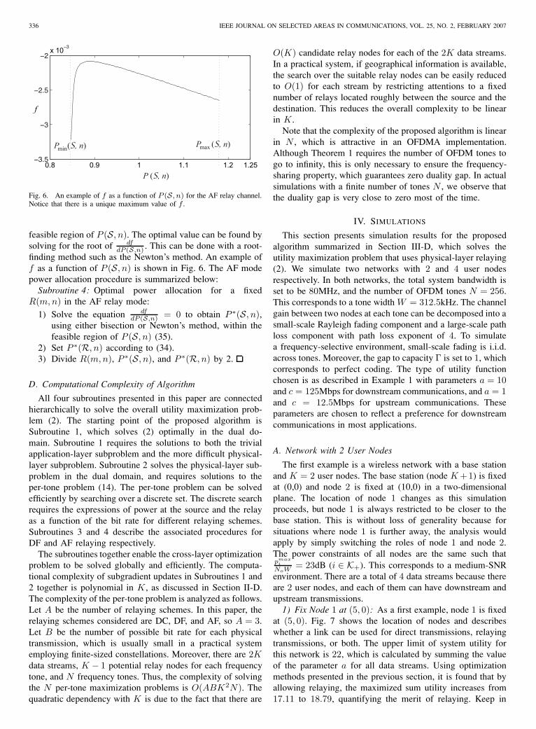
Now, observe that (c3P (S, n) + c4) > 0. Thus, to ensureP ∗(R, n) > 0, the terms (c1P (S, n) + c2) and (c5P (S, n) +c6) must either be both greater than zero or both less thanzero. It is not hard to see that a valid solution is obtainedonly when both terms are less than zero, leading to a feasibleregion for P (S, n) as
Pmin(S, n) < P (S, n) < Pmax(S, n), (35)
wherePmin(S, n) = (2R(m,n)−1)ΓNoW
|hSD|2+|hSR|2 ,
Pmax(S, n) = (2R(m,n)−1)ΓNoW|hSD|2 .
Notice that (35) contains strict inequalities. This is because ifP (S, n) is equal to Pmin(S, n), then P ∗(R, n) will be equalto infinity. On the other hand, P (S, n) cannot be equal toPmax(S, n) either, because this implies P ∗(R, n) = 0, makingAF relaying unnecessary.
Now, it remains to choose the optimal power allocations fora fixed R(m, n). Similar to the analysis in the DF mode, theper-tone objective is as expressed in (14):
maxP (S,n)
λmR(m, n) − µSP (S, n) − µRP ∗(R, n). (36)
Denote the objective function above f . The first step is toshow that f is a concave function of P (S, n). Compute
df
dP (S, n)= −µS − µR
dP ∗(R, n)dP (S, n)
, (37)
d2f
dP (S, n)2= −µR
d2P ∗(R, n)dP (S, n)2
(38)
It can be verified by algebra that for P (S, n) within thefeasible region (35), dP∗(R,n)
dP (S,n) < 0 and d2P∗(R,n)dP (S,n)2 > 0.
Substituting the results into (37) and (38) shows that withinthe feasible region of P (S, n), d2f
dP (S,n)2 < 0, and therebyproving the concavity of f .
The concavity of f and the observation that f is continuousensure that there is a unique optimal value of f within the
336 IEEE JOURNAL ON SELECTED AREAS IN COMMUNICATIONS, VOL. 25, NO. 2, FEBRUARY 2007
0.8 0.9 1 1.1 1.2 1.25
x 10
f
P (S, n)min P (S, n)
P (S, n)
max
Fig. 6. An example of f as a function of P (S, n) for the AF relay channel.Notice that there is a unique maximum value of f .
feasible region of P (S, n). The optimal value can be found bysolving for the root of df
dP (S,n) . This can be done with a root-finding method such as the Newton’s method. An example off as a function of P (S, n) is shown in Fig. 6. The AF modepower allocation procedure is summarized below:
Subroutine 4: Optimal power allocation for a fixedR(m, n) in the AF relay mode:
1) Solve the equation dfdP (S,n) = 0 to obtain P ∗(S, n),
using either bisection or Newton’s method, within thefeasible region of P (S, n) (35).
2) Set P ∗(R, n) according to (34).3) Divide R(m, n), P ∗(S, n), and P ∗(R, n) by 2.
D. Computational Complexity of Algorithm
All four subroutines presented in this paper are connectedhierarchically to solve the overall utility maximization prob-lem (2). The starting point of the proposed algorithm isSubroutine 1, which solves (2) optimally in the dual do-main. Subroutine 1 requires the solutions to both the trivialapplication-layer subproblem and the more difficult physical-layer subproblem. Subroutine 2 solves the physical-layer sub-problem in the dual domain, and requires solutions to theper-tone problem (14). The per-tone problem can be solvedefficiently by searching over a discrete set. The discrete searchrequires the expressions of power at the source and the relayas a function of the bit rate for different relaying schemes.Subroutines 3 and 4 describe the associated procedures forDF and AF relaying respectively.
The subroutines together enable the cross-layer optimizationproblem to be solved globally and efficiently. The computa-tional complexity of subgradient updates in Subroutines 1 and2 together is polynomial in K , as discussed in Section II-D.The complexity of the per-tone problem is analyzed as follows.Let A be the number of relaying schemes. In this paper, therelaying schemes considered are DC, DF, and AF, so A = 3.Let B be the number of possible bit rate for each physicaltransmission, which is usually small in a practical systememploying finite-sized constellations. Moreover, there are 2Kdata streams, K − 1 potential relay nodes for each frequencytone, and N frequency tones. Thus, the complexity of solvingthe N per-tone maximization problems is O(ABK2N). Thequadratic dependency with K is due to the fact that there are
O(K) candidate relay nodes for each of the 2K data streams.In a practical system, if geographical information is available,the search over the suitable relay nodes can be easily reducedto O(1) for each stream by restricting attentions to a fixednumber of relays located roughly between the source and thedestination. This reduces the overall complexity to be linearin K .
Note that the complexity of the proposed algorithm is linearin N , which is attractive in an OFDMA implementation.Although Theorem 1 requires the number of OFDM tones togo to infinity, this is only necessary to ensure the frequency-sharing property, which guarantees zero duality gap. In actualsimulations with a finite number of tones N , we observe thatthe duality gap is very close to zero most of the time.
IV. SIMULATIONS
This section presents simulation results for the proposedalgorithm summarized in Section III-D, which solves theutility maximization problem that uses physical-layer relaying(2). We simulate two networks with 2 and 4 user nodesrespectively. In both networks, the total system bandwidth isset to be 80MHz, and the number of OFDM tones N = 256.This corresponds to a tone width W = 312.5kHz. The channelgain between two nodes at each tone can be decomposed into asmall-scale Rayleigh fading component and a large-scale pathloss component with path loss exponent of 4. To simulatea frequency-selective environment, small-scale fading is i.i.d.across tones. Moreover, the gap to capacity Γ is set to 1, whichcorresponds to perfect coding. The type of utility functionchosen is as described in Example 1 with parameters a = 10and c = 125Mbps for downstream communications, and a = 1and c = 12.5Mbps for upstream communications. Theseparameters are chosen to reflect a preference for downstreamcommunications in most applications.
A. Network with 2 User Nodes
The first example is a wireless network with a base stationand K = 2 user nodes. The base station (node K +1) is fixedat (0,0) and node 2 is fixed at (10,0) in a two-dimensionalplane. The location of node 1 changes as this simulationproceeds, but node 1 is always restricted to be closer to thebase station. This is without loss of generality because forsituations where node 1 is further away, the analysis wouldapply by simply switching the roles of node 1 and node 2.The power constraints of all nodes are the same such thatpmax
i
NoW = 23dB (i ∈ K+). This corresponds to a medium-SNRenvironment. There are a total of 4 data streams because thereare 2 user nodes, and each of them can have downstream andupstream transmissions.
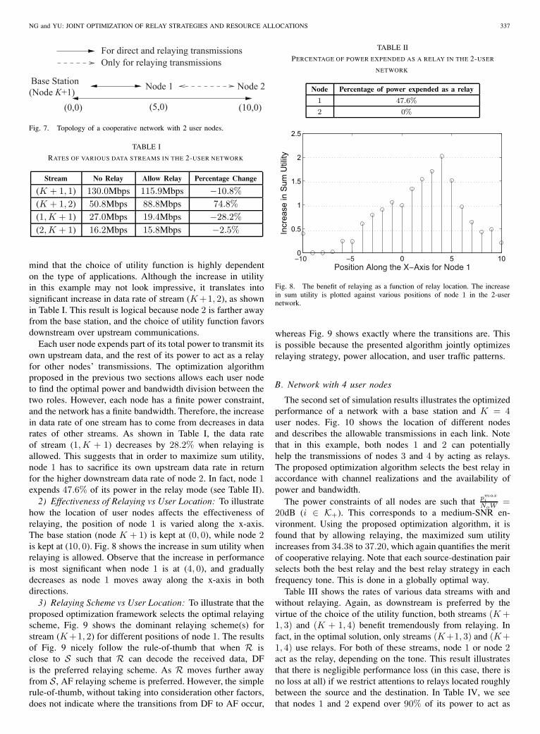
1) Fix Node 1 at (5, 0): As a first example, node 1 is fixedat (5, 0). Fig. 7 shows the location of nodes and describeswhether a link can be used for direct transmissions, relayingtransmissions, or both. The upper limit of system utility forthis network is 22, which is calculated by summing the valueof the parameter a for all data streams. Using optimizationmethods presented in the previous section, it is found that byallowing relaying, the maximized sum utility increases from17.11 to 18.79, quantifying the merit of relaying. Keep in
NG and YU: JOINT OPTIMIZATION OF RELAY STRATEGIES AND RESOURCE ALLOCATIONS 337
For direct and relaying transmissionsOnly for relaying transmissions
(0,0) (10,0)(Node K+1) Node 1
(5,0)
Node 2Base Station
Fig. 7. Topology of a cooperative network with 2 user nodes.
TABLE I
RATES OF VARIOUS DATA STREAMS IN THE 2-USER NETWORK
Stream No Relay Allow Relay Percentage Change
(K + 1, 1) 130.0Mbps 115.9Mbps −10.8%(K + 1, 2) 50.8Mbps 88.8Mbps 74.8%(1, K + 1) 27.0Mbps 19.4Mbps −28.2%(2, K + 1) 16.2Mbps 15.8Mbps −2.5%
mind that the choice of utility function is highly dependenton the type of applications. Although the increase in utilityin this example may not look impressive, it translates intosignificant increase in data rate of stream (K +1, 2), as shownin Table I. This result is logical because node 2 is farther awayfrom the base station, and the choice of utility function favorsdownstream over upstream communications.
Each user node expends part of its total power to transmit itsown upstream data, and the rest of its power to act as a relayfor other nodes’ transmissions. The optimization algorithmproposed in the previous two sections allows each user nodeto find the optimal power and bandwidth division between thetwo roles. However, each node has a finite power constraint,and the network has a finite bandwidth. Therefore, the increasein data rate of one stream has to come from decreases in datarates of other streams. As shown in Table I, the data rateof stream (1, K + 1) decreases by 28.2% when relaying isallowed. This suggests that in order to maximize sum utility,node 1 has to sacrifice its own upstream data rate in returnfor the higher downstream data rate of node 2. In fact, node 1expends 47.6% of its power in the relay mode (see Table II).
2) Effectiveness of Relaying vs User Location: To illustratehow the location of user nodes affects the effectiveness ofrelaying, the position of node 1 is varied along the x-axis.The base station (node K + 1) is kept at (0, 0), while node 2is kept at (10, 0). Fig. 8 shows the increase in sum utility whenrelaying is allowed. Observe that the increase in performanceis most significant when node 1 is at (4, 0), and graduallydecreases as node 1 moves away along the x-axis in bothdirections.
3) Relaying Scheme vs User Location: To illustrate that theproposed optimization framework selects the optimal relayingscheme, Fig. 9 shows the dominant relaying scheme(s) forstream (K +1, 2) for different positions of node 1. The resultsof Fig. 9 nicely follow the rule-of-thumb that when R isclose to S such that R can decode the received data, DFis the preferred relaying scheme. As R moves further awayfrom S, AF relaying scheme is preferred. However, the simplerule-of-thumb, without taking into consideration other factors,does not indicate where the transitions from DF to AF occur,
TABLE II
PERCENTAGE OF POWER EXPENDED AS A RELAY IN THE 2-USER
NETWORK
Node Percentage of power expended as a relay
1 47.6%
2 0%
0 5 100
0.5
1
1.5
2
2.5
Incr
ease
in S
um U
tility
Fig. 8. The benefit of relaying as a function of relay location. The increasein sum utility is plotted against various positions of node 1 in the 2-usernetwork.
whereas Fig. 9 shows exactly where the transitions are. Thisis possible because the presented algorithm jointly optimizesrelaying strategy, power allocation, and user traffic patterns.
B. Network with 4 user nodes
The second set of simulation results illustrates the optimizedperformance of a network with a base station and K = 4user nodes. Fig. 10 shows the location of different nodesand describes the allowable transmissions in each link. Notethat in this example, both nodes 1 and 2 can potentiallyhelp the transmissions of nodes 3 and 4 by acting as relays.The proposed optimization algorithm selects the best relay inaccordance with channel realizations and the availability ofpower and bandwidth.
The power constraints of all nodes are such that pmaxi
NoW =20dB (i ∈ K+). This corresponds to a medium-SNR en-vironment. Using the proposed optimization algorithm, it isfound that by allowing relaying, the maximized sum utilityincreases from 34.38 to 37.20, which again quantifies the meritof cooperative relaying. Note that each source-destination pairselects both the best relay and the best relay strategy in eachfrequency tone. This is done in a globally optimal way.
Table III shows the rates of various data streams with andwithout relaying. Again, as downstream is preferred by thevirtue of the choice of the utility function, both streams (K +1, 3) and (K + 1, 4) benefit tremendously from relaying. Infact, in the optimal solution, only streams (K+1, 3) and (K+1, 4) use relays. For both of these streams, node 1 or node 2act as the relay, depending on the tone. This result illustratesthat there is negligible performance loss (in this case, there isno loss at all) if we restrict attentions to relays located roughlybetween the source and the destination. In Table IV, we seethat nodes 1 and 2 expend over 90% of its power to act as

338 IEEE JOURNAL ON SELECTED AREAS IN COMMUNICATIONS, VOL. 25, NO. 2, FEBRUARY 2007
(10,0)Node 2
°
AF only
DF only
◊ AF and DF♦
°°
°
°
°
°
°
°
◊◊
°°°°°°°°
♦♦
◊◊
°°°°°°°◊◊♦♦
°°°°°
◊
♦◊
♦
°°°◊◊◊◊◊♦♦
◊◊◊◊◊◊◊◊♦♦
° ◊◊◊◊◊◊◊♦♦
◊◊◊◊◊
◊♦♦♦♦
♦♦♦♦♦
♦°
°°◊
♦♦
°°° °°°◊
°°°°°
°°
°°°°°°°°◊
°°°°
°°◊◊
°♦♦
♦♦♦
♦♦♦♦
°°°°°°°◊
♦♦
°°°°°°◊◊♦
♦♦
°°°°°◊◊♦
°◊◊◊♦♦♦
♦♦♦
◊◊
♦♦♦
(0,0)Base Station(Node K+1)
(0,10)
Fig. 9. The dominant relay mode (AF or DF) for stream (K + 1, 2) forvarious positions of node 1 in the 2-user network. “AF and DF” indicates thatAF and DF are both likely to occur, depending on the channel realizations ineach tone. The DC mode is not shown here, but it occurs frequently for allpositions of node 1, especially when node 1 is far away from the base stationand/or node 2.
Base Station
Node 3(7,3)
(0,0)
(1,1)
Node 4
Fir direct and relaying transmissionsOnly for relaying transmissions
(Node K + 1)
Node 1
Node 2
Fig. 10. Topology of a cooperative network with 4 user nodes.
a relay. These results illustrate that in a system with optimalallocations of bandwidth and power that truly maximizes thesum utility, nodes 1 and 2 would sacrifice their own data ratesfor the benefits of nodes 3 and 4.
V. CONCLUSION
This paper proposes a utility maximization framework forthe joint optimization of the best relay node, the best relaystrategy, and the best power, bandwidth and rate alloca-tions in a cellular network. Both amplify-and-forward anddecode-and-forward relaying strategies are considered. Byusing a dual optimization technique for OFDMA systems,the seemingly difficult system optimization problem is solvedefficiently and globally using a pricing structure. Specifically,the pricing structure decomposes the optimization probleminto application-layer and physical-layer subproblems. Thephysical-layer subproblem can be further decomposed intoper-tone optimization problems, which makes the overallcomputational complexity linear in the number of tones. Thispaper illustrates that by adopting a cross-layer approach thattakes into account both the power and bandwidth availabilityand the traffic demand of each user, cooperative relaying inthe physical layer has the potential to significantly improvethe overall system performance.
TABLE III
RATES OF VARIOUS DATA STREAMS IN THE 4-USER NETWORK
Stream No Relay Allow Relay Percentage Change
(K + 1, 1) 152.8Mbps 148.4Mbps −2.9%(K + 1, 2) 135Mbps 129.4Mbps −4.1%(K + 1, 3) 46.6Mbps 71.3Mbps 53.0%(K + 1, 4) 54.1Mbps 80.5Mbps 48.8%(1, K + 1) 18.8Mbps 16.6Mbps −11.7%(2, K + 1) 18.8Mbps 16.3Mbps −13.3%(3, K + 1) 11.9Mbps 13.8Mbps 16.0%(4, K + 1) 14.1Mbps 13.4Mbps −5.0%
TABLE IV
PERCENTAGE OF POWER EXPENDED AS A RELAY IN THE 4-USER
NETWORK
Node Percentage of power expended as a relay
1 94.9%
2 92.2%
3 0%
4 0%
REFERENCES
[1] R. U. Nabar, H. Bolcskei, and F. W. Kneubuhler, “Fading relay channels:performance limits and space-time signal design,” IEEE J. Sel. AreasCommun., vol. 22, no. 6, pp. 1099–1109, Aug. 2004.
[2] A. Nosratinia, T. E. Hunter, and A. Hedayat, “Cooperative communica-tion in wireless networks,” IEEE Commun. Mag., vol. 42, no. 10, pp.74–80, Oct. 2004.
[3] J. N. Laneman and G. W. Wornell, “Distributed space-time codedprotocols for exploiting cooperative diversity in wireless networks,”IEEE Trans. Inf. Theory, vol. 49, no. 10, pp. 2415–2425, Oct. 2003.
[4] J. N. Laneman, D. N. C. Tse, and G.W.Wornell, “Cooperative diversityin wireless networks: efficient protocols and outage behavior,” IEEETrans. Inf. Theory, vol. 50, no. 12, pp. 3062–3080, Dec. 2004.
[5] A. Sendonaris, E. Erkip, and B. Aazhang, “User cooperation diversity–part I: system description,” IEEE Trans. Commun., vol. 51, no. 11, pp.1927–1938, Nov. 2003.
[6] ——, “User cooperation diversity–part II: implementation aspects andperformance analysis,” IEEE Trans. Commun., vol. 51, no. 11, pp. 1939–1948, Nov. 2003.
[7] A. Stefanov and E. Erkip, “Cooperative coding for wireless networks,”IEEE Trans. Commun., vol. 52, no. 9, pp. 1470–1476, Sept. 2004.
[8] R. Pabst, B. Walke, D. Schultz, P. Herhold, H. Yanikomeroglu,S. Mukherjee, H. Viswanathan, M. Lott, W. Zirwas, M. Dohler, H. Agh-vami, D. Falconer, and G. Fettweis, “Relay-based deployment conceptsfor wireless and mobile broadband radio,” IEEE Commun. Mag., vol. 42,no. 9, pp. 80–89, Sept. 2004.
[9] H. Viswanathan and S. Mukherjee, “Performance of cellular networkswith relays and centralized scheduling,” IEEE Trans. Wireless Commun.,vol. 4, no. 5, pp. 2318–2328, Sept. 2005.
[10] J. Cho and Z. J. Haas, “On the throughput enhancement of the down-stream channel in cellular radio networks through multihop relaying,”IEEE J. Sel. Areas Commun., vol. 22, no. 7, pp. 1206–1219, Sept. 2004.
[11] H.-Y. Hsieh and R. Sivakumar, “On using peer-to-peer communicationin cellular wireless data networks,” IEEE Trans. Mobile Comput., vol. 3,no. 1, pp. 57–72, Jan. 2004.
[12] T. M. Cover and A. A. E. Gamal, “Capacity theorems for the relaychannel,” IEEE Trans. Inf. Theory, vol. 25, no. 5, pp. 572–584, Sept.1979.
[13] V. Sreng, H. Yanikomeroglu, and D. Falconer, “Relay selection strategiesin cellular networks with peer-to-peer relaying,” in Proc. IEEE Veh.Technol. Conf. (VTC-Fall), pp. 1949–1953.
[14] M. Yu and J. Li, “Is amplify-and-forward practically better than decode-and-forward or vice versa?” in Proc. IEEE Inter. Conf. Acoustics,Speech, and Signal Processing, (ICASSP), vol. 3, Mar. 2005, pp. 365–368.

NG and YU: JOINT OPTIMIZATION OF RELAY STRATEGIES AND RESOURCE ALLOCATIONS 339
[15] B. Can, H. Yomo, and E. D. Carvalho, “A novel hybrid forwardingscheme for OFDM based cooperative relay networks,” in Proc. IEEEInter. Conf. Commun. (ICC) 2006.
[16] M. A. Khojastepour, A. Sabharwal, and B. Aazhang, “On the capacity of‘cheap’ relay networks,” in Proc. 37th Annu. Conf. Information Sciencesand Systems (CISS) 2003, pp. 12–14.
[17] ——, “On capacity of Gaussian ‘cheap’ relay channel,” in Proc. IEEEGlobal Telecommun. Conf. (GLOBECOM) 2003, pp. 1776–1780.
[18] A. Wittneben and B. Rankov, “Impact of cooperative relays on thecapacity of rank-deficient MIMO channels,” in Proc. 12th IST Summiton Mobile Wireless Communications 2003, pp. 421–425.
[19] M. Dohler, A. Gkelias, and H. Aghvami, “A resource allocation strat-egy for distributed MIMO multi-hop communication systems,” IEEECommun. Lett., vol. 8, no. 2, pp. 99–101, Feb. 2004.
[20] J. Luo, R. S. Blum, L. Cimini, L. Greenstein, and A. Haimovich,“Power allocation in a transmit diversity system with mean channelgain information,” IEEE Commun. Lett., vol. 9, no. 7, pp. 616–618,July 2005.
[21] A. Host-Madsen and J. Zhang, “Capacity bounds and power allocationfor wireless relay channels,” IEEE Trans. Inf. Theory, vol. 51, no. 6, pp.2020–2040, June 2005.
[22] M. O. Hasna and M.-S. Alouini, “Optimal power allocation for relayedtransmissions over Rayleigh-fading channels,” IEEE Trans. WirelessCommun., vol. 3, no. 6, pp. 1999–2004, Nov. 2004.
[23] I. Maric and R. D. Yates, “Bandwidth and power allocation for coop-erative strategies in Gaussian relay networks,” in Proc. Thirty-EighthAsilomar Conference on Signals, Systems and Computers, vol. 2, pp.1907–1911.
[24] J. Adeane, M. R. D. Rodrigues, and I. J. Wassell, “Centralised anddistributed power allocation algorithms in cooperative networks,” inProc. IEEE 6th Workshop on Signal Processing Advances in WirelessCommunications (SPAWC) 2005, pp. 333–337.
[25] X. Deng and A. M. Haimovich, “Power allocation for cooperativerelaying in wireless networks,” IEEE Commun. Lett., vol. 9, no. 11,pp. 994–996, Nov. 2005.
[26] A. Reznik, S. R. Kulkarni, and S. Verdu, “Degraded Gaussian multirelaychannel: capacity and optimal power allocation,” IEEE Trans. Inf.Theory, vol. 50, no. 12, pp. 3037–3046, Dec. 2004.
[27] M. Chen, S. Serbetli, and A. Yener, “Distributed power allocation forparallel relay networks,” in Proc. IEEE Global Telecommun. Conf.(GLOBECOM) 2005, vol. 3, Nov. 2005, pp. 1177–1181.
[28] E. G. Larsson and Y. Cao, “Collaborative transmit diversity withadaptive radio resource and power allocation,” IEEE Commun. Lett.,vol. 9, no. 6, pp. 511–513, June 2005.
[29] S. Serbetli and A. Yener, “Optimal power allocation for relay assistedF/TDMA ad hoc networks,” in Proc. Inter. Conf. Wireless Networks,Commun. and Mobile Comp., vol. 2, pp. 1319–1324.
[30] Y. Liang and V. V. Veeravalli, “Resource allocation for wireless relaychannels,” in Proc. 38th Asilomar Conference on Signals, Systems andComputers, vol. 2, pp. 1902–1906.
[31] ——, “Gaussian orthogonal relay channels: optimal resource allocationand capacity,” IEEE Trans. Inf. Theory, vol. 51, no. 9, pp. 3284–3289,Sept. 2005.
[32] G.-D. Yu, Z.-Y. Zhang, Y. Chen, S. Chen, and P.-L. Qiu, “Powerallocation for non-regenerative OFDM relaying channels,” in Proc. Inter.Conf. Wireless Commun., Networking and Mobile Comp. (WCNC) 2005,vol. 1, pp. 185–188.
[33] K. Lee and A. Yener, “On the achievable rate of three-node cognitivehybrid wireless networks,” in Proc. International Conference on Wireless
Networks, Communications and Mobile Computing 2005, vol. 2, pp.1313–1318.
[34] K. Chen, Z. Yang, C. Wagener, and K. Nahrstedt, “Market modelsand pricing mechanisms in a multihop wireless hotspot network,” inProc. Second Annual Inter. Conf. on Mobile and Ubiquitous Systems:Networking and Services (MobiQuitous) 2005, pp. 73–82.
[35] O. Ileri, S.-C. Mau, and N. Mandayam, “Pricing for enabling forwardingin self-configuring ad hoc networks,” IEEE J. Sel. Areas Commun.,vol. 23, no. 1, pp. 151–162, Jan. 2005.
[36] F. P. Kelly, A. Maulloo, and D. Tan, “Rate control for communicationnetworks: shadow prices, proportional fairness and stability,” J. Opera-tions Research Society, vol. 49, no. 3, pp. 237–252, 1998.
[37] G. Song and Y. G. Li, “Cross-layer optimization for OFDM wirelessnetworks–part I: theoretical framework,” IEEE Trans. Wireless Com-mun., vol. 4, no. 2, pp. 614–624, Mar. 2005.
[38] ——, “Cross-layer optimization for OFDM wireless networks–part II:algorithm development,” IEEE Trans. Wireless Commun., vol. 4, no. 2,pp. 625–634, Mar. 2005.
[39] W. Yu and R. Lui, “Dual methods for nonconvex spectrum optimizationof multicarrier systems,” IEEE Trans. Commun., vol. 54, no. 7, pp.1310–1322, July 2006.
[40] N. Z. Shor, Minimization Methods for Non-differentiable Functions.Springer, 1985.
[41] S. Boyd, L. Xiao, and A. Mutapcic, “Subgradient methods,” lecturenotes of EE392o, Stanford University, Autumn Quarter 2003-2004.
[42] R. Cendrillon, W. Yu, M. Moonen, J. Verlinden, and T. Bostoen,“Optimal spectrum balancing for digital subscriber lines,” IEEE Trans.Commun., vol. 54, no. 5, pp. 922–933, May 2006.
Truman Chiu-Yam Ng received the B.A.Sc. degreein computer engineering from the University ofWaterloo, Waterloo, ON, Canada, in 2004, and theM.A.Sc. degree in electrical engineering from theUniversity of Toronto, Toronto, ON, Canada, in2006. His areas of research are wireless relay chan-nels, information theory, and convex optimizationtechniques.
Wei Yu (S’97-M’02) received the B.A.Sc. degreein Computer Engineering and Mathematics from theUniversity of Waterloo, Waterloo, Ontario, Canadain 1997 and M.S. and Ph.D. degrees in ElectricalEngineering from Stanford University, Stanford, CA,in 1998 and 2002, respectively. Since 2002, he hasbeen an Assistant Professor with the Electrical andComputer Engineering Department at the Universityof Toronto, Toronto, Ontario, Canada, where heholds a Canada Research Chair. His main researchinterests are multiuser information theory, optimiza-
tion, wireless communications and broadband access networks.Prof. Yu is currently an Editor of the IEEE Transactions on Wireless
Communications. He was a Guest Editor of the IEEE Journal on SelectedAreas in Communications (Special Issue on Nonlinear Optimization onCommunication Systems) in 2006, and a Guest Editor of EURASIP Journalon Applied Signal Processing (Special Issue on Advanced Signal Processingfor Digital Subscriber Lines) in 2005.