3.1 introduction: design responsibility and applicability ...€¦ · sewer design and construction...
TRANSCRIPT

3-1
SECTION 3
Sewer Design and Construction
3.1 Introduction: Design Responsibility and Applicability of Requirements
The design and construction requirements for sewer collection systems included in this Manual are applicable for any development located within the City of Auburn (including the 5-mile planning jurisdiction) that intends to obtain sewer services from the City upon successfully meeting all of the City’s requirements for obtaining such services.
The Water Resource Management (WRM) Department of the City of Auburn shall enforce the requirements included in this Manual on behalf of the City of Auburn. Privately maintained sewer collection systems are not required to meet all of the design standards included in this Manual for sewer collection systems. Any standards, included in this Manual, which are required by a federal or state regulatory authority, or any applicable local plumbing codes shall be required and enforced by those specific authorities.
This Manual is intended to provide general guidance and minimum criteria for the design and construction of sewer facilities for development. However, the sole responsibility for the design is that of the engineer for the development.
Generally, this Manual is intended to be used for the typical subdivision and small-scale commercial development. The typical subdivision development would be a development that needs no more than a 12-inch gravity sewer main. Developments that need sewer services greater than this size are not considered typical developments. Although this Manual can be used for general guidance for other than typical developments, requirements for these developments will be handled on a case-by-case basis. A Utility Installation Flow Chart for site plan development projects and residential subdivision development projects is included in Appendix C of this Manual.
The engineer is encouraged to meet with and discuss each development with the WRM Department prior to the submittal of the plans for review.
Any costs attributable to the extension of the sewer collection system to serve a single development shall be the responsibility of the developer.
SECTION 3. SEWER DESIGN AND CONSTRUCTION
3-2
3.2 General Considerations 3.2.1 Existing Sewer Facilities All existing sewer facilities that are located within the project area or that will be affected by the development must be located, identified, and shown on the plans. It is the responsibility of the engineer to have any and all utilities located and shown accurately on the plans.
If, during construction, any utilities are discovered that were not shown on the plans, the WRM Department shall be notified immediately. The construction on any area of the project affected by the discovered utility may be halted and the plans may need to be revised and resubmitted for review at the discretion of the WRM Department.
Any existing sewer mains or services, currently maintained by the City of Auburn, shall be evaluated by the WRM Department to determine if they can be reused for development when a construction plan submittal is required for the development. Any existing sewer service that will be reused for a development must be brought to current standards of the City of Auburn.
Any existing sanitary sewer services that are not to be used should be abandoned, per City requirements. Typically, this requires terminating the sewer lateral at the ROW or edge of easement and sealing the end of the lateral to prevent infiltration into the sewer system. Laterals shall be sealed by installing an approved and secured plug or cap and shall be encased in concrete. Laterals that are temporarily abandoned for future use shall be marked in accordance with the requirements of Section 3.4.9.1 of this Manual for future location identification. All lateral abandonments shall be inspected by the City prior to backfilling.
The WRM Department requires any new Food Service Facility (FSF) connected to the City’s sanitary sewer system to comply with the current requirements for Fats, Oils, and Grease (FOG) protection. This shall include all retrofits into existing buildings regardless of previous use.
Where existing onsite sewer treatment (or septic) systems are to be abandoned to make a new connection to the sanitary sewer collection system, the septic system shall be properly abandoned in accordance with the Alabama Department of Public Health regulations. A new service lateral will be required to connect to the public sewer main. In no case will a connection be allowed directly from a septic system to the City’s sewer collection system.
3.2.2 Proposed Sewer Facilities The plans submitted for review shall show all proposed sewer services, including all proposed sewer mains, manholes, laterals, cleanouts, grease traps, oil and grit separators, pool drains, and any other features associated with the sewer system. All diameters, material, locations, elevations, and pertinent features shall be identified clearly on the plans. Any proposed sanitary sewer pump stations shall also be clearly identified and described in detail on the plans, including a completed design of all associated components in accordance with the requirements in Section 3.5 of this Manual.
3.2.3 System Capacity Analysis The WRM Department will verify sewer availability as well as collection and treatment capacity to serve a development in the City of Auburn with the assistance of the developer and engineer, where necessary. All developments are required to estimate the sewer capacity required in the
SECTION 3. SEWER DESIGN AND CONSTRUCTION
3-3
Application for Water and Sewer Service (Appendix B) that shall be submitted at the time of plan submittal.
The WRM Department may require that a system capacity analysis be performed during the plan review process. The exact requirements of the system capacity analysis will be handled on a case-by-case basis. Any and all such costs for the study or required infrastructure surveying will be the responsibility of the developer.
Any upgrades to the existing sewer facilities necessary to provide adequate service to the development typically would be the responsibility of the developer. If the existing infrastructure, in the opinion of the WRM Department, is not sufficient to serve the development, the developer may be required to participate in or to fully fund any necessary offsite infrastructure upgrades to obtain sewer service. The amount of developer participation will depend on the amount of contiguous developable area that may be served by the expansion and the corresponding need of the City-approved capital improvement plan. Developer participation in infrastructure improvements or expansions may be detailed in the Development Agreement, where required.
Once a development, that is to be served sewer by the City of Auburn, has been reviewed and approved by the DRT, the City will reserve sewer capacity for the development, and the development will be allowed to connect to the sewer collection system as shown on the approved plans until said DRT approval expires, which is typically 18 months from the date of approval. Once DRT approval has expired, reserved capacity shall subsequently expire and the WRM Department will reevaluate the City’s capacity to serve the development when the plans are resubmitted for review and approval in accordance with the DRT requirements in this Manual. Reserved capacity will also be reviewed by the WRM Department prior to any requested extension of DRT approval, including preliminary plat or conditional use extension requests as they affect the DRT approval period.
SECTION 3. SEWER DESIGN AND CONSTRUCTION
3-4
3.3 Submittal Requirements The design engineer shall submit a complete set of design plans for review. The submitted plans shall be a complete set, comprehensive in all details of the design. The requirement to submit a set of design plans that are of a complete design shall not prevent an engineer from meeting with the WRM Department and submitting a “preliminary” design for recommendations and preliminary comments from the WRM Department. However, the WRM Department will only review and provide written comments on a completed set of design plans that are submitted for review.
The submitted set of plans shall include the following:
• Overall sewer main layout of entire development with existing and proposed contours shown and all manhole elevations labeled
• Detailed sewer main plan/profile sheets
• All existing and proposed sewer facilities labeled and clearly differentiated
• Manholes, including all rim and invert elevations, sequentially numbered
• Identification of all pipe sizes and materials
• Sewer laterals
• Minimum finished floor elevations
• Grease traps and future grease trap locations
• All standard details that are required
• Any unique details /notes relevant to the project
• All standard notes
• Sanitary sewer pump station information (where required)
• Any engineering calculations (where required)
• Location of all other utilities adjacent to or crossing sewer mains
Additional requirements for the plans submitted for review are included in the City of Auburn Site Development Plans Submittal Checklist and the Subdivision Construction Plans Submittal Checklist (Appendix B). When the individual development is part of a larger Master Development Plan, the engineer may be required to submit an “overall sewer layout” for the entire larger development for review.
SECTION 3. SEWER DESIGN AND CONSTRUCTION
3-5
3.4 Gravity Sewer Design and Layout 3.4.1 Sewer Main Location The preferred location for sanitary sewers will be beneath pavement, located in the middle of the street or in low-lying areas where the maximum surrounding area can be served. The sanitary sewer gravity system shall be designed to be straight between any manholes (i.e., no curved sections of gravity sewer between manholes shall be permitted). Sewer main alignment and grade shall be verified by the use of a laser leveling device.
The sanitary sewer system shall be located with consideration given to the following:
• Development of contiguous areas
• Ability to serve basements by gravity service, where possible
• Any environmentally sensitive areas, such as wetlands or creeks
• Any other existing (or proposed) utilities
• Location of any permanent structures
• Location of any streams, water bodies, or other water features
• Any steep slopes (natural or filled)
• Any areas that would hinder future access and maintenance
• Proposed street extensions
• Any proposed future site grading
• Any areas that would require excessive depth (greater than 20 feet)
• Any future development that may affect the sewer system
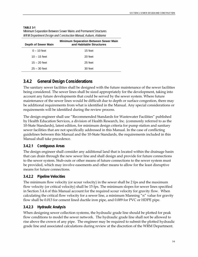
Sewer mains shall be located in an area free from surface obstructions (signs, walls, utility poles, structures, ponds, water features, canopy trees, etc.) that, in the opinion of the WRM Department, would make maintenance or repairs to the sewer main more difficult. Sewer mains shall be a minimum of 15 feet from all permanent structures, stream banks, water bodies, or dam structures. Sewer mains with depths greater than 10 feet will require additional separation from these obstructions, as listed in Table 3-1
The Contractor shall place utility line markers on all wastewater conveyance lines in unpaved areas and where development has not yet been established. Markers shall be placed at all manholes for gravity systems, and a minimum of every 250 feet for force mains. Utility markers shall be 66 inch green Rhino 3-rail fiberglass marking post or approved equal.
SECTION 3. SEWER DESIGN AND CONSTRUCTION
3-6
TABLE 3-1 Minimum Separation Between Sewer Mains and Permanent Structures WRM Department Design and Construction Manual, Auburn, Alabama
Depth of Sewer Main Minimum Separation Between Sewer Main
and Habitable Structures
0 – 10 feet 15 feet
10 – 15 feet 20 feet
15 – 20 feet 25 feet
25 – 30 feet 30 feet
3.4.2 General Design Considerations The sanitary sewer facilities shall be designed with the future maintenance of the sewer facilities being considered. The sewer lines shall be sized appropriately for the development, taking into account any future developments that could be served by the sewer system. Where future maintenance of the sewer lines would be difficult due to depth or surface congestion, there may be additional requirements from what is identified in the Manual. Any special considerations or requirements will be identified during the review process.
The design engineer shall use “Recommended Standards for Wastewater Facilities” published by Health Education Services, a division of Health Research, Inc. (commonly referred to as the 10-State Standards), latest edition, for minimum design criteria for pump station and sanitary sewer facilities that are not specifically addressed in this Manual. In the case of conflicting guidelines between this Manual and the 10-State Standards, the requirements included in this Manual shall take precedence.
3.4.2.1 Contiguous Areas The design engineer shall consider any additional land that is located within the drainage basin that can drain through the new sewer line and shall design and provide for future connections to the sewer system. Stub-outs or other means of future connections to the sewer system must be provided, which may involve easements and other means to allow for the least disruptive means for future connections.
3.4.2.2 Pipeline Velocities The minimum flow velocity (or scour velocity) in the sewer shall be 2 fps and the maximum flow velocity (or critical velocity) shall be 15 fps. The minimum slopes for sewer lines specified in Section 3.4.4 of this Manual account for the required scour velocity for gravity flow. When calculating the critical flow velocity for a sewer line, a minimum Manning “n” value for gravity flow shall be 0.013 for cement lined ductile iron pipe, and 0.009 for PVC or HDPE pipe.
3.4.2.3 Hydraulic Analysis When designing sewer collection systems, the hydraulic grade line should be plotted for peak flow conditions to model the sewer network. The hydraulic grade line shall not be allowed to rise above the crown of any pipe. The engineer may be required to submit the plotted hydraulic grade line and associated calculations during review at the discretion of the WRM Department.

SECTION 3. SEWER DESIGN AND CONSTRUCTION
3-7
Manholes shall be designed so that the flow transitions smoothly across the invert and turbulence is minimized. The outgoing pipe invert elevation shall be lowered as necessary to maintain a smooth energy gradient across the manhole. Where multiple lines combine in a single manhole, each line shall be analyzed separately to determine the appropriate exit elevation. All manholes shall have an elevation drop across the invert. At a minimum there shall be a 0.10 foot drop where the manhole does not include a break in direction greater than 22 degrees and a 0.25 foot drop if the manhole includes a break in the direction greater than 22 degrees for a standard 48 inch diameter manhole.
3.4.2.4 Capacity Estimation Criteria Sanitary sewers shall be designed using commonly accepted design standards, using per-capita flow rates. Sewers shall be designed to flow half full at peak flow. If requested, the engineer must provide the calculations and assumptions used in sizing sanitary sewer lines.
In general, the sewer collection system shall be designed based on 250 gallons per day per unit (gpd/unit) and shall use a minimum peaking factor of 2.5. This requirement would be applicable for a sanitary sewer system serving primarily residential developments. For systems that would serve significant commercial or industrial developments, the design engineer will be required to provide flow data for review during design.
In the case of commercial developments or large subdivisions, the engineer may be required to perform a capacity analysis of both the proposed and existing sewer systems and to provide these to the WRM Department for review.
If the WRM Department determines that the existing sanitary sewer line does not have the capacity to accept wastewater from the proposed development, the engineer may be required to prepare an engineering analysis to propose alternatives.
3.4.2.5 Lowest Floor Elevations Gravity sanitary sewer mains shall be designed so that the lowest floor elevation of any structure that is served by public sewer is at least 12 inches above the rim elevation of the connection manhole or the nearest upstream manhole. If the lowest floor elevation is not 12 inches above the manhole rim elevation, the customer shall install a private pump station for the sewer service or an approved backwater valve on the private gravity service line capable of preventing sewer backflows into the structure. Backwater valves installed on the customer’s service line shall be normally-open to avoid flow restriction during normal use and shall be installed in a location that is accessible for maintenance and repairs. Approved normally-open backwater valves for interior basement installation or where the external depth of cover is less than 24 inches shall be “Fullport” backwater valves manufactured by Mainline Backflow Products, Inc. as shown in Figure 3-1, or an approved equal. Approved normally-open backwater valves for installation in external applications where the depth of cover will be greater than 24 inches shall be an “Adapt-a-Valve” backwater valve manufactured by Mainline Backflow Products, Inc. or an approved equal.

SECTION 3. SEWER DESIGN AND CONSTRUCTION
3-8
FIGURE 3-1
Fullport Backwater Valve Mainline Backflow Products, Inc.
Each lot of record within the development shall be noted on the plans and the plat as having a potential backflow issue, where the finished grades are such that the lowest floor elevation of a structure served by public sewer could potentially be less than 12 inches above the manhole rim elevation. The property owners, successors, and assigns shall indemnify, hold harmless, and defend the City for any backflows that occur due to improper maintenance, repairs, use, or omittance of this device. If the property will not be platted as a result of the development, a hold-harmless agreement will be required prior to DRT approval.
The WRM Department will evaluate each development for potential backflow issues during plan review, however, it is the engineer’s responsibility to determine the lots or units that are affected by this requirement and shall indicate them on the construction plans prior to submittal.
3.4.3 Sanitary Sewer Connections All connections to existing sanitary sewer mains and manholes within the City of Auburn’s sewer collection system must be approved and properly permitted by the WRM Department before they can be made. Sanitary Sewer Connection permits can be acquired from the WRM Department. Application for connection to the sanitary sewer system of the City shall be made by the Owner of the premises to be served or his duly authorized agent, on an application form provided by the City, conditioned upon the agreement of the Owner to be bound by City Rules and Regulations and the WRM Design and Construction Manual. The application form can be found on the City’s website and shall be submitted electronically. In special instances where the applicant may not have access to a computer, hard copies of the form may be obtained from and turned in at the WRM Department. A copy of the Sanitary Sewer Connection Permit Application can be found in Appendix B of the WRM Design and Construction Manual. At least 48 hours should be accounted for review and approval of all sewer connection permits by WRM. Prior to submitting the permit application, a plan for all sewer connections shall be submitted to the WRM Department for review and approval if not included in a previous DRT submittal. The plan shall include the location of the sewer connection, including the address or

SECTION 3. SEWER DESIGN AND CONSTRUCTION
3-9
lot number to be served, the size of the water meter serving the property, the size, type and kind of material proposed for the connection, and any other pertinent information that may reasonably be required by the WRM and City to evaluate the application and plan. Developments that are required to submit plans to the DRT, in accordance with the standards included in this Manual, shall receive DRT approval prior to receiving approval for a sanitary sewer connection. All connections to existing sanitary sewer mains and manholes shall be done in the presence of a City inspector or a representative of the WRM Department. The Sanitary Sewer Connection Permit will be provided to the appropriate City inspector or WRM Department representative by the WRM Department upon approval for the authorization of the connection.
The Owner is responsible for all costs associated with the installation of the new sewer service and for hiring a contractor, who must be a licensed and bonded General Contractor carrying the designation of MU-(S) - Sewer. The work will generally include the installation of a new sewer tap and service pipe or sewer lateral line between the City’s sanitary sewer main and the premises to be served, including cleanout at the right-of-way or edge of easement, and any other appurtenances that may be required in accordance with City Rules and Regulations and the WRM Design and Construction Manual. It shall also be the responsibility of the Owner to ensure that all site conditions are restored as appropriate, such as, but not limited to, asphalt, curb, gutter, sidewalks, etc.
All access fees shall be paid before the work begins. No sewage service will be furnished through any new connection until a certification has been issued by the City Codes Enforcement Officer certifying that all plumbing and fixtures have been installed in accordance with the City Plumbing Code.
3.4.4 Sewer Size and Materials The minimum sewer size for a public gravity sewer main shall be 8 inches. Solid-wall PVC pipe SDR 35 or SDR 26 may be used for sewer mains, provided that the depth of cover is between 3 feet and 12 feet, and there are no unusual loadings or concerns. The cover requirements for PVC pipe will not be changed with increased pipe thickness classification. High-density polyethylene (HDPE) pipe DR 9 is also allowed on a case-by-case basis for installations between depths of 3 feet and 12 feet. Gravity sewer mains with less than 3 feet of cover shall be ductile iron Pressure Class 350 or Thickness Class 51. Gravity sewer mains installed with more than 12 feet of cover shall be ductile iron, of the appropriate Thickness Class for the installation.
Changes in pipe sizes and/or materials shall not be allowed between manholes.
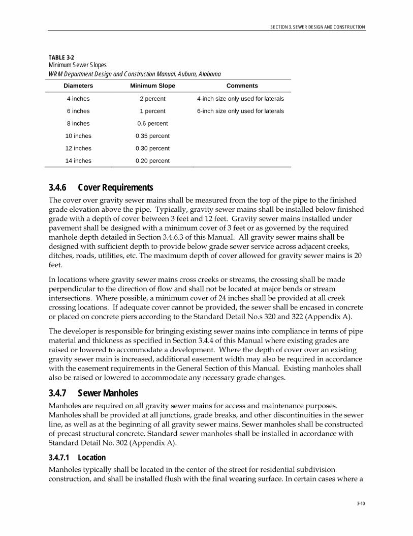
3.4.5 Minimum Slopes Table 3-2 lists the minimum slopes for sewers. Gravity sewer lines shall be laid to grade with uniform slope between manholes. The diameter of the sewer line may not be increased above that which is necessary from a capacity standpoint to obtain a shallower design grade.
SECTION 3. SEWER DESIGN AND CONSTRUCTION
3-10
TABLE 3-2 Minimum Sewer Slopes WRM Department Design and Construction Manual, Auburn, Alabama
Diameters Minimum Slope Comments
4 inches 2 percent 4-inch size only used for laterals
6 inches 1 percent 6-inch size only used for laterals
8 inches 0.6 percent
10 inches 0.35 percent
12 inches 0.30 percent
14 inches 0.20 percent
3.4.6 Cover Requirements The cover over gravity sewer mains shall be measured from the top of the pipe to the finished grade elevation above the pipe. Typically, gravity sewer mains shall be installed below finished grade with a depth of cover between 3 feet and 12 feet. Gravity sewer mains installed under pavement shall be designed with a minimum cover of 3 feet or as governed by the required manhole depth detailed in Section 3.4.6.3 of this Manual. All gravity sewer mains shall be designed with sufficient depth to provide below grade sewer service across adjacent creeks, ditches, roads, utilities, etc. The maximum depth of cover allowed for gravity sewer mains is 20 feet.
In locations where gravity sewer mains cross creeks or streams, the crossing shall be made perpendicular to the direction of flow and shall not be located at major bends or stream intersections. Where possible, a minimum cover of 24 inches shall be provided at all creek crossing locations. If adequate cover cannot be provided, the sewer shall be encased in concrete or placed on concrete piers according to the Standard Detail No.s 320 and 322 (Appendix A).
The developer is responsible for bringing existing sewer mains into compliance in terms of pipe material and thickness as specified in Section 3.4.4 of this Manual where existing grades are raised or lowered to accommodate a development. Where the depth of cover over an existing gravity sewer main is increased, additional easement width may also be required in accordance with the easement requirements in the General Section of this Manual. Existing manholes shall also be raised or lowered to accommodate any necessary grade changes.
3.4.7 Sewer Manholes Manholes are required on all gravity sewer mains for access and maintenance purposes. Manholes shall be provided at all junctions, grade breaks, and other discontinuities in the sewer line, as well as at the beginning of all gravity sewer mains. Sewer manholes shall be constructed of precast structural concrete. Standard sewer manholes shall be installed in accordance with Standard Detail No. 302 (Appendix A).
3.4.7.1 Location Manholes typically shall be located in the center of the street for residential subdivision construction, and shall be installed flush with the final wearing surface. In certain cases where a
SECTION 3. SEWER DESIGN AND CONSTRUCTION
3-11
street location is not a feasible route to provide gravity sewer, the manholes shall be located in the low-lying areas, adjacent to streams, or in a location such that the majority of the sewer basin can be served. Manhole locations shall take into consideration the ability to service future developments of contiguous areas and adjacent properties that are not currently served by sewer.
All manholes in undeveloped areas shall be a minimum of one foot above finished grade. Manhole lids located within 1 vertical foot of the 100-year floodplain elevation shall be water-tight gasketed with lock-down lid, and anchor ring. The watertight manhole cover and ring shall be in accordance with Standard Detail No. 310 (Appendix A). Where the finished grade elevation at the manhole is 3 feet or less below the 100-year floodplain elevation, risers shall be utilized to extend the rim elevation to 1 foot above the 100-year floodplain elevation. The maximum extension of a manhole shall be 4 feet above the ground surface. Manholes shall be located a minimum of 15 feet from any stream bank or water body.
All manholes located within the 100-year flood plain shall have a concrete waterproofing admixture of the cementitious crystalline type, such as Xypex admix C-500R or approved equal, added according to the product manufacturer’s specifications.
3.4.7.2 Spacing Sewer manholes shall be spaced as necessary to provide turns and grade breaks in the sewer main. Sewer manholes shall be spaced a maximum of 400 feet apart to allow for maintenance of the sewer main. A minimum spacing of 100 feet shall be provided, where possible.
3.4.7.3 Shape and Dimensions Sewer manholes shall be cylindrical in shape with a concentric cone section on top. Manholes that are box shaped or that have flat top sections shall not be allowed.
Sewer manholes shall be sized according to the main size, connections, and degree of directional change in the main line. The minimum diameter of sewer manholes shall be 48 inches for typical sewer installation. Larger manholes may be required on lines larger than 12 inches, or where the angle between the invert in and invert out is less than 120 degrees.
The height of a manhole shall be measured from the outgoing invert elevation to the rim elevation. The minimum height of a sewer manhole shall be 50 inches, providing adequate space for a standard precast concentric base cone section, ring, and cover. Specialty precast concentric manhole sections requiring less height may be submitted by the engineer for review as part of the construction plans, where available. In all cases, clear line of sight shall be maintained from the rim to all pipe inverts. Flat top manhole sections and risers shall not be allowed. Special consideration shall be provided by the engineer for manholes designed in paved areas, or where the rim elevation cannot be extended above the finished grade elevation, to ensure that the minimum manhole height is provided in the cover over the sewer line.
The maximum depth of a sewer manhole will be controlled by the maximum cover of 20 feet allowed for gravity sewer mains, with additional height allowed above finished grade, where applicable.
SECTION 3. SEWER DESIGN AND CONSTRUCTION
3-12
3.4.7.4 Connections Connections in manholes shall be done in a manner to provide as little turbulence and disruption to the flow as possible. All connections shall be directed into the flow smoothly by shaping the invert or apron to accommodate all incoming sewer lines. The invert shall be formed and poured to provide a smooth transition across the manhole. Directional change in the main line through a manhole shall be no less than 90 degrees between the invert in and invert out.
Manhole connections shall be sealed appropriately to minimize groundwater infiltration into the sewer system. Typical sealing methods include the use of a rubber boot around the connecting pipe as well as grouting the annular space between the pipe and the connection core. Other methods of sealing the connection points may be used as approved by the WRM Department.
Where adjacent connections are required to be cored into manholes for 4 and 6 inch service lines, the minimum separation between the connections shall not be less than 6 inches. The minimum separation between adjacent connections larger than 6 inches in diameter shall not be less than the largest diameter of the connecting lines. Connection separation shall be measured from the nearest edges of the connection cores.
There shall be a minimum of 0.10 foot drop across manholes where there is not a turn greater than 22 degrees and a minimum of 0.25 foot drop across manholes where there is a turn 22 degrees or greater. The turning angle shall be measured as the difference between the bearing direction of the incoming pipe and the bearing direction of the outgoing pipe.
Memphis Tees shall be used to construct a drop manhole whenever the elevation drop is 2 feet or greater. The Memphis Tee shall be installed outside the manhole if the pipe diameter is greater than 6 inches. Drop manholes shall be installed in accordance with Standard Details No. 300 and 306 (Appendix A).
Saddle manhole connections shall be used where a new sewer main is proposed to tie into an existing sewer main mid-span between existing manholes. Saddle manholes shall be installed in accordance with Standard Detail No. 304 (Appendix A).
3.4.8 Separation of Sewer and Water Lines In general, sewer and water lines shall be separated by a minimum of 10 feet horizontally and 18 inches vertically. This distance shall be measured from the outside edge of the pipelines.
Where proper horizontal separation cannot be attained, the sewer line shall be ductile iron and shall be hydrostatically pressure tested to 150 psi. In no case will a sewer line be allowed within 5 feet horizontally of a water main.
Where proper vertical separation cannot be attained, the sewer line shall be ductile iron and shall either be installed in a steel casing that extends a minimum of 10 feet past the centerline of the crossing, or hydrostatically pressure tested to 150 psi. All sewer main casings shall be installed in accordance with Section 3.4.8 of this Manual and Standard Detail No. 324 (Appendix A). All crossings shall be laid out so that they are perpendicular and centered on a section of pipe, providing the maximum spacing between the joints and the crossing.
SECTION 3. SEWER DESIGN AND CONSTRUCTION
3-13
3.4.9 Road Bores and Casings Road borings for sewer mains will typically be required in lieu of open-cut trenching methods when crossing existing paved streets in the City of Auburn or when crossing a county, state, or federal highway or railroad. This determination will be made on a case specific basis by the City’s Public Works Department and/or the appropriate ROW authority, where applicable.
Where road borings are required, they shall be a traditional jack-and-bore construction method using a steel casing. Where possible, the steel casing shall extend at least 5 feet beyond the edge of the roadway or planned roadway widening, but shall in no case continue within 5 feet of a service connection or cleanout. When casings are installed for gravity sewer and manholes are needed at the ends of the casings, the manholes shall be set back far enough to allow for excavation and maintenance of the sewer line without requiring the removal of the manhole. A typical set-back distance would be 25 feet. Directional drilling methods shall not be allowed for the installation of sewer mains and services.
All bores for sewer mains and services shall be placed on proper grade and delivered precisely to the location shown on the construction plans with uniform slope and direction. It is recommended that the engineer design the jack-and-bore crossings at a grade slightly steeper than the minimum to allow for variations in the as-constructed slopes for the installed sewer. The minimum slopes as provided for sewer lines are applicable and will be enforced for sewer lines installed in jack-and-bore casings.
Where sewer service connections are being made, the existing sewer main shall be excavated as part of the receiving pit, prior to setting up the bore, to verify the necessary depth and grade shown on the construction plans. All other utilities shall be located and potholed, where necessary, prior to performing the bore. Where open-cut trenching methods are allowed across an existing paved street for new sewer mains and services, the repair shall be made in accordance with the standards of the appropriate ROW authority.
Steel casings also may be required if, in the opinion of the WRM Department, the sewer mains are located in an area that would make maintenance on the sewer main difficult or impractical. Installing sewer mains in such areas will be at the discretion of the WRM Department, and will only be allowed where there are no alternatives for providing gravity sewer service to a development. Steel casings shall be sized according to the carrier pipe size with appropriately sized spacers to center the pipe in the encasement. The carrier pipe shall be ductile iron, and the pipe joints shall be restrained using external restraint mechanisms or locking gasket restraints for retrieval of the pipe from the encasement. The ends of the encasement shall be sealed with brick and mortar or with a rubber boot and double stainless steel straps to prevent water from entering the casing. Encasements shall be installed per the City’s Standard Detail No. 324 (Appendix A).
3.4.10 Sewer Laterals 3.4.10.1 Location Sewer laterals shall typically be installed directly from a sewer manhole or main perpendicular to the ROW, easement, or property line. Sewer laterals shall be located in areas free from obstructions in maintaining continuous grade and alignment. All sanitary sewer lateral and stub out locations shall be identified by an "S" marked in the concrete gutter and on the face of the curb where streets are being built. The contractor shall bury a marker ball locator (Tempo

SECTION 3. SEWER DESIGN AND CONSTRUCTION
3-14
Omni Marker Model 162, 121.6 kHz, or approved equal) at the ROW or edge of easement where the lateral terminates. Marker balls and disks should not be buried more than 3 feet below proposed final grade. The contractor shall also mark the termination point of the lateral above grade using a green Rhino 3-rail fiberglass marking post or approved equal.
3.4.10.2 Size Where possible, a sewer lateral shall only serve a single-platted lot or a single piece of property. Individual service laterals, with a minimum diameter of 4 inches, shall be provided for each dwelling unit when serving single-family subdivisions, duplexes, townhomes, or similar segmented residential development. Multi-family or combined residential development such as apartment complexes or condominium complexes shall be served by a single sewer lateral sized sufficiently to handle the expected sewer capacity.
Sewer laterals shall be greater than 4 inches in diameter where serving more than a single-dwelling or commercial unit, or where the water meter size is greater than 1 inch. Where two single-dwelling units must be connected to the same service lateral, the cleanout shall be placed at the property line between the units.
Sewer lateral material shall be in accordance with Section 3.4.3 of this Manual from the main to the property line, easement line, ROW, or where the City’s maintenance ends. Sewer laterals shall be installed at the minimum slopes noted in Table 3-1.
3.4.10.3 Connections Sewer laterals shall be connected to a manhole, where possible, with a maximum of four connections. An exception to the number of connections will be made in the case of beginning manholes, where five connections are permitted. A maximum of two Memphis tee connections will be allowed to an individual manhole.
Internal Memphis Tees are required for 4-inch to 6-inch laterals if the connections are 2 feet above the flow line. The internal Memphis Tees should be directed into the flow line. Where sewer lateral connections are less than 2 feet above the flow line, the lateral or the apron shall be adjusted so that the connection is no more that 4 inches above the apron. Where a lateral is to be connected to an existing manhole where the existing main is larger than 12 inches in diameter, the invert of the connection should be made above the crown of the existing main. Where a lateral is to be connected to an existing manhole where the existing main is 12 inches in diameter or smaller, the connection can be lowered to a crown-to-crown elevation. Laterals entering beginning manholes shall be directed into the flow line with no drop allowed.
Where sewer laterals must be connected directly to a sewer main, the connections shall be separated by a minimum of 3 feet. For new sewer main installation, the contractor shall install an inline “tee” or “wye” in all locations where a lateral is proposed to connect directly to the main. Where it becomes necessary to tap an existing main, such connection shall be made with an approved type saddle fitting, either a “tee” or “wye” connection. The saddle shall be placed over a carefully cut opening in the upper quadrant of the sewer main and attached to the main using stainless steel straps. Under no circumstances shall any lateral connection be allowed to protrude into the sewer main.
SECTION 3. SEWER DESIGN AND CONSTRUCTION
3-15
3.4.10.4 Cleanouts All sewer laterals shall be installed with cleanouts. At least one cleanout shall be installed at the ROW or easement line, and another at the building, in accordance with the local plumbing code. Typically, publicly maintained sewer laterals shall be designed to not be long enough to require multiple cleanouts. Where long public sewer service laterals are required, and approved by the WRM Department, a sewer cleanout shall be installed at a spacing not to exceed 100 feet. Cleanout spacing for privately maintained laterals shall be in accordance with the currently adopted local plumbing code.
If a cleanout is located in pavement or concrete, the cleanout shall be installed in a traffic-rated enclosure, per the Standard Detail No. 330 (Appendix A).
3.4.11 Grease Traps Grease traps are required to prevent fats, oils, and grease (FOG), typically discharged by food production or processing operations, from entering and becoming a hazard to the sanitary sewer system.
Grease traps are required for all Food Service Facilities (FSFs) which shall include, but is not limited to, any restaurant, eatery, food caterer, cafeteria, grocery store, manufacturing facility, or institution which cuts, cooks, bakes, prepares, serves, or makes available for consumption any food products by any prescribed method, or which disposes of food related wastes.
Grease traps shall be required on all FSFs including all new construction, redevelopments, or retrofit applications that connect to the City of Auburn sewer collection system regardless of previous use. Grease traps shall be shown and detailed on the plans for current or future intended use. The grease trap shall meet all applicable local plumbing codes, any applicable county and state health department requirements, and shall be of a sufficient size to handle the grease loading and provide adequate detention time from the facility as defined in Section 3.4.10.2 of this Manual. All fixtures associated with food production and preparation which may potentially contain grease laden waste shall be connected to the grease trap. All domestic sanitary sewer (i.e. restroom sewer) shall be plumbed separately from grease laden waste lines and shall only be combined into a single discharge line beyond the outlet of the grease trap and required sampling port.
The grease trap shall be cleaned and inspected regularly and shall meet all discharge requirements as specified in the City’s Sewer Ordinance. Any FSF found to not be in compliance with the specified discharge requirements shall be required to immediately install additional FOG protection prior to the public sewer connection at the expense of the FSF owner.
3.4.11.1 Location Grease traps shall be located in an area that can be easily accessed for maintenance, cleaning, and inspection. They shall not be located in an entrance, exit, drive-through, or under a menu board, sign, or structure. If the trap is located in a drive or parking area, it must contain traffic-rated rings and covers and meet H-20 loadings. Manhole rings and covers shall not be covered or obscured by landscaping, pavement, or other obstructions.
Grease trap locations shall also be considered by the design engineer for all commercial sites that potentially will require a grease trap for future intended uses. Strip retail centers or commercial developments comprising of multiple units should consider including separately
SECTION 3. SEWER DESIGN AND CONSTRUCTION
3-16
plumbed sewer connections for each unit that can be used to retrofit a grease trap connection if the proposed use changes to a FSF. Multiple adjacent FSFs on the same property may also be plumbed to a common on-site grease trap, if desired, provided that the grease trap is sized appropriately for all the proposed plumbing fixtures that will drain to it. If a common grease trap is not designed for proposed multiple adjacent retail units, the engineer shall provide locations for future grease traps to be installed that shall be identified on the construction plans and approved by the WRM Department.
3.4.11.2 Design The design engineer shall submit sizing calculations on the Standard Grease Trap Size Calculation Data Sheet (Appendix B) to the WRM Department for each grease trap that is installed. The sizing calculation is derived from the 2009 Uniform Plumbing Code detention time calculation, which is based on the determined fixture unit values.
FSFs shall be classified according to the FOG loading based on the operational characteristics of the facility as Light or Heavy FOG Producers. Light FOG producers shall only be applicable to FSFs where the products used in food preparation and service contain little or no dairy, shortening, oil, butter, vegetable fat, animal fat, or other fatty compounds which are insoluble in water at room temperature, as deemed appropriate by the WRM Department.
Grease traps for FSFs meeting the criteria of a Light FOG Producer shall be a minimum of 500 gallons to provide a minimum detention time of 30 minutes. Grease traps for Heavy FOG Producers shall be a minimum of 1000 gallons to provide a minimum detention time of 1 hour. Consideration also should be given by the designing engineer in regard to the type and nature of the facility requiring the grease trap to determine if the volume of the trap should be increased beyond the detention time requirement to properly handle the expected grease loading and to minimize the required regular cleaning and maintenance for the owner.
Grease traps shall be required to have a minimum of two access manholes for cleaning and inspection. A sampling port or manhole is also required downstream of the grease trap. No other connections to the sewer line are allowed between the grease trap and the sampling location.
The inlet and outlet pipes of the grease trap shall be Schedule 40 PVC. The open-ended tee used to extend the inlet and outlet below the fluid level shall not be covered or capped. The inlet pipe must be a minimum of 4 inch diameter, and the vertical pipe on the outlet side must be a minimum of 6 inch diameter. The WRM Department recommends installing 2 inch diameter vents connected to the building vent system from each chamber of the grease trap in order to prevent odors and gas collection.
Grease traps shall be designed and installed in accordance with Standard Detail No. 316 (Appendix A).
3.4.11.3 Alternative Grease Removal Device In certain cases, where existing and unavoidable site constraints are present that would prohibit a FSF from installing an external grease trap in accordance with the standards outlined in this Manual, the WRM Department may be willing to review alternative grease removal devices, such as internal automatic grease recovery systems, or devices with enhanced engineered baffling systems as proposed by the developer for attaining grease protection for the sewer

SECTION 3. SEWER DESIGN AND CONSTRUCTION
3-17
system. The proposed alternative grease removal device shall be required to meet the discharge requirements as specified in the City’s Sewer Ordinance.
Alternative grease removal devices shall be installed in a readily and easily accessible location for cleaning, maintenance, and inspection. The device shall be designed, sized and installed in accordance with the manufacturer’s specifications and shall be connected downstream of all fixtures that, in the opinion of the WRM Department, will produce FOG laden wastewater. Multiple devices may be required to facilitate the appropriate fixtures and/or anticipated flow. Such installations shall comply with all applicable building and plumbing codes.
Approved automatic grease recovery systems shall include a solids separator, heating element, and an automatic grease recovery mechanism. The FOG shall be removed from the wastewater and stored in a separate container that can easily be removed and transported for proper disposal.
All alternative grease removal devices shall be approved by the WRM Department prior to installation. Small volume, passive interceptors (i.e., “under-the-sink” type devices) shall not be considered as an acceptable alternative grease removal device to provide adequate protection for FOG entering the sewer system.
3.4.12 Oil and Grit Separators Oil and grit separators will be required at all commercial car washes, equipment wash bays, automotive service or repair stations, mechanical equipment service or repairs stations, and similar garages and facilities that would discharge polluted wastewater as deemed necessary by the WRM Department. The oil and grit separators shall meet all applicable local plumbing codes and be of a sufficient size to handle the specified loading for the intended use. The oil and grit separators shall be cleaned and inspected regularly and shall meet all discharge requirements as specified in the City’s Sewer Ordinance.
3.4.12.1 Location Oil and grit separators shall be located in an area that can be easily accessed for maintenance, cleaning, and inspection. They shall not be located in an entrance, exit, drive-through, or under a menu board, sign, or structure. If the separator is located in a drive or parking area, it must contain traffic-rated rings and covers and meet H-20 loadings. Manhole rings and covers shall not be covered or obscured by landscaping, pavement, or other obstructions.
3.4.12.2 Design Oil and grit separators shall be a minimum of 1,000 gallons unless otherwise approved by the WRM Department. The design engineer shall submit sizing calculations, assumptions, and typical performance data for each installation to the WRM Department. Additional information and treatment parameters for oil and grit separators are provided in Section 4.4.11 of this Manual for storm water quality treatment that can also be used in the design of systems connecting to the sanitary sewer collection system.
Oil and grit separators shall be required to have a minimum of two access manholes for cleaning and inspection. A sampling manhole also is required downstream of the separator. No other connections to the sewer line are allowed between the separator and the sampling manhole.
SECTION 3. SEWER DESIGN AND CONSTRUCTION
3-18
The inlet and outlet pipes of the oil and grit separator shall be Schedule 40 PVC. The open-ended tee used to extend the inlet and outlet below the fluid level shall not be covered or capped. The inlet pipe must be a minimum of 4-inch diameter and the vertical pipe on the outlet side must be a minimum of 6-inch diameter.
Oil and grit separators shall be designed and installed in accordance with Standard Detail No. 318 (Appendix A).
3.4.13 Open Surface Drains An open surface drain is considered any connection that would collect stormwater such as grade inlets, roof drains, vault drains, etc. Open surface drains generally are not allowed to be connected to the sanitary sewer system. However, certain cases may require these drains to connect to sanitary sewer because of the nature and pollution hazard of the potential discharge and will be evaluated on a case-by-case basis by the WRM Department. Developments that include drains for items such as large trash compactors or commercial car washes will be required to connect to the sanitary sewer. All open surface drains connecting to the sanitary sewer will be assessed a surcharge based on the drainage area and amount of stormwater being treated. The drainage area shall be provided on the Water and Sewer Application for Service Form (Appendix B), and shall be clearly identified on a schematic drawing with the proposed site contours that shall be submitted to the WRM Department.
Garbage dumpster pad drains shall be tied to the storm system, or graded to drain away from the area, if necessary for the development, and shall not be allowed to tie into the sanitary sewer collection system.
3.4.14 Pool Drains Swimming pools that are constructed for public use, private community or organization use, or with a volume greater than 30,000 gallons will be required to connect the drain line to the sanitary sewer system to avoid chemical release into local streams or water bodies. Swimming pool drain connections made to sanitary sewer shall be no larger than 2 inches in diameter and shall in no case exceed 50 GPM of flow, either by gravity or pumped discharge, to avoid surcharging the collection system. Swimming pools connected to the sanitary system shall not be filled through the use of an irrigation meter.
Typical single-family residential swimming pools with volumes smaller than 30,000 gallons will not be required to connect the drain line to the sanitary sewer system.
SECTION 3. SEWER DESIGN AND CONSTRUCTION
3-19
3.5 Sanitary Sewer Pump Station and Force Main Design 3.5.1 Discussion Where technically feasible, the means for providing sanitary sewer service to a development shall be by gravity sewer, without the use of any pump stations.
The WRM Department realizes that there are certain developments that, because of unique circumstances, cannot be served by gravity sanitary sewer systems.
The WRM Department will look at each separate development on its unique circumstances and work with the developer to determine the best way to provide the needed services that are in the best long-term interest of the City and its citizens. All sanitary sewer pump stations that are approved shall be constructed to the City’s standards.
It is the City’s intent to minimize the number of sanitary sewer pump stations that are located in the service area.
Pump stations shall be designed with regional intent in mind. A cost sharing and regional planning concept should be used to provide for the most cost-effective means to provide public sewer for developments.
The WRM Department reserves the right to require the developer to participate in a cost-shared regional type pump station to be designed by the WRM Department, when, in the opinion of the WRM Department, such an arrangement is in the best interest of the City.
The maximum size of a pump station that will be allowed to be designed by the developer will be 250-gpm firm design capacity. The City shall reserve the right to contract the design and inspection of any pump station proposed for a single development with a firm design capacity larger than 250 gpm at the full cost of the developer. No pump station will be considered for an individual development that would serve fewer than 50 equivalent residential dwelling units.
Private pump stations and force mains used to connect to the City’s sewer collection system shall only be allowed for a single customer connection, lot of record, or residential dwelling unit (i.e., individually owned grinder pump station). No privately maintained pump stations or force mains will be approved for servicing multiple connections.
3.5.2 Submittal Requirements No development will be approved that includes a sanitary sewer pump station without a detailed engineering report having been submitted to the WRM Department for review. This report must include an evaluation of any alternatives to a sanitary sewer pump station and include cost estimates for the alternatives evaluated. At the City’s request, the report also will include a conceptual analysis of the regional sewer service area. If a development is considering the installation of a sanitary sewer pump station, the developer must contact the WRM Department to discuss the development during conceptual planning and prior to the initial submittal of the plans to the DRT.
The design engineer shall submit a complete design package to the WRM Department for review prior to DRT submittal for the development. All pump station design data, reports, drawings, studies, specifications, calculations, pump curves, supervisory control and data acquisition (SCADA) information, and any other design information submitted for review shall

SECTION 3. SEWER DESIGN AND CONSTRUCTION
3-20
be stamped and sealed by a registered engineer in the State of Alabama in the appropriate and specific discipline of service (i.e., civil, electrical, etc.). The review time required by the WRM Department for developments, including sanitary sewer pump stations, will vary depending on the specific details of the pump station and the development. The design engineer shall coordinate any necessary review meetings with the WRM Department to facilitate the review process.
The design engineer shall submit a complete set of pump station design drawings for each pump station. A general pump station site and section layout is provided on Standard Details No. 336 and 338 (Appendix A). These drawings are provided as a general guide for the design engineer in preparation of the design drawing package for the pump station.
The design engineer shall submit all design calculations and assumptions for review. The design calculations shall include all sizing criteria, assumptions, references, etc., to provide the WRM Department with a complete design package for review.
The pump station drawing package shall include the following:
• Overall site plan
• Grading plan (existing and proposed)
• Pump station section views
• Plan and profile of gravity sewer onsite
• Plan and profile of force main, including all air release valves
• Electrical drawings (including power feed and control panel wiring schematics)
• SCADA details
• Access roads and site fencing
• Stormwater drainage plan
3.5.3 General Design Considerations The information presented in this Manual is to be used by the design engineer in the design of a sanitary sewer pump station. The design engineer shall also use Recommended Standards for Wastewater Facilities, published by Health Education Services, a division of Health Research, Inc. (commonly referred to as the 10-State Standards) as a general design guide for any criteria that are not covered as part of this Manual.
3.5.4 Mechanical 3.5.4.1 Submersible Pumps The pump station layout shall include, at a minimum, a submersible, duplex pump arrangement with the firm design capacity being met with the largest pump out of service. The firm design capacity shall be equal to the estimated peak design flow. For residential development, incoming average daily flow (ADF) can be estimated as 250 gallons per day per dwelling unit. A peaking factor based on the development size shall be applied to determine the
SECTION 3. SEWER DESIGN AND CONSTRUCTION
3-21
design capacity of the pump station, as defined in the Pump Station Calculation Worksheet (Appendix B).
Criteria for estimating flow for any non-residential development being served by a pump station shall be submitted to the WRM Department with the pump station design calculations. Additional information may also be required by the WRM Department during review in regards to the type of waste and operational characteristics of any non-residential developments where needed for proper pump selection.
The pumps shall be set up in a lead-lag arrangement, alternating the lead pump with each cycle. A maximum of five starts per hour is allowed for each pump, and a minimum of two starts per hour is required at maximum build out.
Submersible pumps shall be at a minimum vertical, double mechanical sealed, non-clog, solids handling pumps capable of passing a 3-inch-diameter sphere. Submersible grinder pumps are not acceptable. Pump suction and discharge openings shall be a minimum of 4 inches in diameter, and each pump shall have an individual intake.
The pump casing and volute shall be constructed of heavy-duty cast iron or stainless steel. The impeller shall be constructed of stainless steel or abrasion-resistant cast iron. The shaft shall be constructed of stainless steel and shall be supported by heavy-duty, sealed, anti-friction bearings. The bearings shall be sized to handle all expected loads and shall have a minimum rating of 50,000 hours. The casing and impeller shall be fitted with removable and replaceable wear rings. The elastomer seals shall be constructed of nitrile rubber.
The submersible pumps shall be equipped with a double mechanical seal to prevent leakage into the pump shaft. The primary (outer) seal shall be constructed of tungsten carbide and/or silicon carbide faces with stainless-steel fittings and shall be equipped with a moisture detection switch to activate a warning alarm in case of seal failure. The secondary (inner) seal shall be constructed of carbon steel. Ceramic faces shall not be acceptable.
The pump motor shall meet the requirements of Section 3.5.5.3 of this Manual.
Submersible pumps shall be specified based on the site-specific conditions of the pump station. The design shall take into account head conditions, type of waste, flow rate, impeller type, motor size, need for future upgrades, etc. The top and bottom elevation of the pumps shall be shown on the pump station drawings.
Pumps shall be manufactured by ABS, Flygt, KSB, Hydromatic, or an approved equal.
3.5.4.2 Guide Rails and Hoist All pump stations shall be equipped with guide rails for extracting the pumps from the wet well. The sliding guide bracket shall be an integral part of the pump unit. The pump lifting chain shall be sized to accommodate the installed pump weight, but shall in no case be sized smaller than 3/16 of an inch diameter links. All guide rails, lifting chains, clevises, shackles, hook assemblies, guide rail brackets, anchors, bolts, nuts, and other exposed metal shall be ASTM A276 Type 316 stainless steel.
All pump stations shall include a portable hoist with an adjustable reach from 24 inches to 36 inches. The winch shall have a minimum load rating of 1,000 pounds. The hoist shall be installed with a socket embedded in a concrete base adjacent to the top of the wet-well. The
SECTION 3. SEWER DESIGN AND CONSTRUCTION
3-22
hoist shall be Halliday Products-Series D2B Portable Hoist with Series D Portable Hoist Socket, or an approved equal. The hoist shall be provided with a weather-resistant cover.
3.5.4.3 Standby Diesel Pump All pump stations shall be equipped with an onsite standby diesel pump. The standby pump shall be self-priming and capable of solids handling. The standby pump shall be sized to handle the firm design capacity of the pump station. A separate intake line for the standby pump shall be extended to the low water level inside the wet well. The standby pump shall operate on a separate float system from the submersible pumps and shall have separate motor controls. Contacts for run status of the standby pump shall be provided for indication in the SCADA system. The fuel capacity of the standby pump shall be sufficient to allow for a 24-hour run time. The standby pump shall be a Godwin Dri-Prime Pump or an approved equal.
The standby pump shall be equipped with an electric start kit. A battery tender, trickle charging system shall be installed of the appropriate manufacturer size and specification for the motor size, battery voltage, and power requirements of the specific pump.
The standby pump shall be installed in a sound attenuated enclosure to reduce the operating noise produced by the diesel-driven pump. The standby pump shall be equipped with a silenced muffler and priming exhaust. The enclosure shall be a Godwin Pumps, Critically Silenced Enclosure, or an approved equal. A drain line shall be provided from the standby pump enclosure to the wet well.
The standby pump shall be skid mounted and shall be anchored to a concrete pad with stainless-steel anchor bolts. The concrete shall at a minimum consist of Class A concrete in accordance with the City of Auburn Standard Specification with a minimum thickness of 6 inches. The concrete pad shall also be installed in accordance with the pump manufacturer’s recommendations.
3.5.4.4 Isolation Valves All isolation valves installed at sanitary sewer pump stations and on sanitary sewer force mains shall be either resilient-seated gate valves or eccentric plug valves with a minimum port opening equal to 100 percent of the adjacent pipe area, thereby providing maximum passage of solids. The valves shall be rated for a minimum 150-psi working pressure.
Each pump discharge shall have an isolation valve installed after the check valve in the valve vault. The valves shall be the same nominal dimension as the discharge piping.
Valves installed in a vault shall include a hand wheel-operated actuator. Each underground valve shall be provided with a cast iron valve box to house and protect the valve stem. All valve boxes installed in unpaved areas shall have a concrete collar installed according to Standard Detail No. 332 (Appendix A). If a precast collar is used the annular space between the valve box and the concrete collar shall be grouted in. Ductile iron or cast iron pipe shall not be used as valve box extension unless approved. PVC should never be used as a valve box extension.
Isolation valves on force mains shall be installed at a maximum spacing of 500 feet between valves and on both sides of all creek crossings.
SECTION 3. SEWER DESIGN AND CONSTRUCTION
3-23
3.5.4.5 Check Valves A check valve shall be installed on each pump discharge including the submersible pumps, the standby diesel pump, and the quick connection to the force main for bypass pumping. The check valves shall be swing type with an external arm and counter weight, and shall have flanged ends, a cast iron body, solid bronze hinges, and a stainless-steel hinge shaft. Check valves shall be rated to a minimum 150-psi working pressure and shall be manufactured in compliance with AWWA C508.
3.5.4.6 Air Release Valves Three general types of automatic ARVs are used on sewer force mains:
• Standard ARVs (small orifice valves): Designed for the slow release of air during pumping operations
• Air/Vacuum Valves (large orifice valves): Designed to release large amounts of air during filling operations, and to admit large amounts of air during draining
• Combination Air Vacuum/ARVs (small and large orifice): Designed to perform both functions of small and large orifice ARVs
Typically, ARVs used in force main applications shall be Combination Air Vacuum/ARVs capable of releasing small amounts of air during normal pumping operations and admitting large amounts of air to break the vacuum when the pumps are turned off. Small orifice ARVs may be used in certain cases where not much grade change occurs in the force main and air vacuum relief is not necessary. Small orifice ARVs also may be required on steep sections of a force main to release trapped air intermittently between combination ARVs that are located at the high points.
ARVs, at a minimum, shall be installed at all high points and at a distance between ARVs not to exceed 1,500 feet. The high points shall be field verified during construction to ensure appropriate placement, and the ARVs shall be installed on a level section of pipe equidistant between the joints. The pipe should continually slope between ARVs except on the joint of pipe where the ARV is installed.
ARVs installed on force mains shall be specifically manufactured for use in wastewater applications. The valve body and hardware shall be constructed of Type 316 stainless steel. The sealing mechanism shall be ethylene-propylene-diene M-class rubber (EPDM) and shall be activated by an HDPE control float. The large intake and discharge orifice area shall be equal to the nominal size of the valve. The small discharge orifice shall be sized based on the flow of air required to evacuate from the force main during filling operations. ARVs shall be manufactured by Vent-O-Mat, ARI, or an approved equal.
ARVs shall be sized appropriately to vent and admit air when all pumps are in operation and shall be sized and located in accordance with the design criteria provided in the AWWA Manual M51, Air-Release, Air/Vacuum, & Combination Air Valves. ARVs shall be installed in accordance with the Standard Detail No. 334 (Appendix A).
SECTION 3. SEWER DESIGN AND CONSTRUCTION
3-24
3.5.5 Electrical The electrical design shall be prepared by an electrical engineer registered in the State of Alabama for all sewer pump stations. The design shall comply with National Fire Protection Association (NFPA) Article 820, the Institute of Electrical and Electronics Engineers (IEEE), and the National Electrical Code (NEC), as well as all local electrical codes. The standards included in this section shall be considered minimum requirements for the electrical design of a sanitary sewer pump station.
3.5.5.1 Classification The wet well of a sewer pump station is classified as a Class I, Division 1 or 2, Group D hazardous location, per NFPA Article 820. The electrical design shall be suitable for this environment, which shall include, but is not limited to, intrinsically safe, hermetically sealed float switches; explosion-proof motors and junction boxes; rigid galvanized conduit (no PVC); and appropriately sealed wet well penetrations.
3.5.5.2 Power Supply Pump stations shall be served by utility supplied three-phase power for pumps greater than 7 HP. An Underwriters Laboratories, Inc. (UL), recognized three-phase power monitor shall interrupt the control power in the event of phase loss, phase reversal, low voltage, and phase unbalance. The power monitor shall have primary fuse protection. The contacts shall be rated for 15A resistive at 120 volts alternating current (VAC).
The use of single-phase power and a phase converter will only be considered three-phase power is not available or the cost to acquire three-phase power is excessive. The use of phase-converters must be approved prior to design. If a phase converter is to be used, the plans shall detail the converter installation. All phase converter installations shall meet the following requirements:
• Rotary-type converters are unacceptable.
• All wiring ahead of the three-phase panel shall be protected with single-phase fusing sized to meet the total single-phase amperage; conductors shall be sized based on single-phase amperage and fusing.
• Converters shall be sized to operate the total installed pump station amperage with all pumps running.
• A static phase shift method converter shall be a Ronk “Add-a-phase,” manufactured by Ronk Electrical Industries, Inc. (or approved equal). The converter shall be housed in a locking National Electrical Manufacturers Association (NEMA)-3R, rain-tight, stainless-steel enclosure.
• Variable Frequency Drives (VFD) may be used for phase conversion. The horsepower rating must be increased to meet the three-phase load requirement of the motor.
• A 5-year warranty bond shall be provided on all electrical equipment and pumps if phase conversion is used.
The design engineer shall contact the electrical utility and determine the utility requirements for motor starting and any soft-start requirements. Correspondence with the electrical utility shall
SECTION 3. SEWER DESIGN AND CONSTRUCTION
3-25
be copied to the City, along with design submittals. For most installations, the standard electrical supply shall be 480 volt (V), and 60 Hertz (Hz). All control panels, circuit breakers, and other electrical equipment shall be located inside the fenced site.
The surge protector shall be parallel metal oxide varistor (MOV) design and shall provide protection for Category C Transient Surges, as defined in American National Standard Institute (ANSI)/IEEE C62.41 without degradation of components. Protection shall be provided between each phase line and the ground line. The surge protection shall be Stedi-Volt, V-Blox, or approved equal.
The electrical system shall also be protected by a lightening arrestor capable of handling up to 600 VAC.
A 110V, ground fault interrupter (GFI), two-plug outlet inside a weather enclosure shall be provided and have a dedicated 15A circuit breaker. The outlet shall be located at the electrical control panel.
3.5.5.3 Motors All pump stations shall include explosion-proof motors, with a maximum speed of 1,800 revolutions per minute (rpm). Motors shall be high efficiency, using copper winding, Class F or H insulation, and heavy varnish. The motor shall be non-overloading for the entire pump curve. The motor electrical design shall comply with NEMA Design B. The motors shall be equipped with thermal overload protectors embedded in each phase of the windings to sense high temperatures.
The pump motor shall be housed in an air-filled or oil-filled water tight chamber designed to operate continuously in a non-submerged application. The chamber shall be constructed of heavy-duty cast iron. The cable entry shall be sealed to prevent capillary leakage into the motor chamber. The motor and motor housing shall be bolted to the pump body to allow for removal and repair.
Motors shall be supplied with a high-quality, factory-applied epoxy coating system.
3.5.5.4 Control Panel The pump control panel system shall be fabricated by a current UL 698A-listed industrial control panel manufacturer. The panel manufacturer shall show its UL follow-up service procedure file number on submittals. All devices within the panel shall be UL listed and/or recognized where applicable and shall be mounted and wired in accordance with the most current edition of UL 698 A and NFPA. Wiring shall include standard numbering and color coding for clear identification. The panel shall be factory assembled, wired, and fully tested before shipment. Testing shall include both power and control devices, as well as all control functions. A final inspection shall be performed before shipment and a copy of this form shall be provided with the panel. The panel manufacturer shall supply two sets of as-wired drawings to the City upon completion of construction.
An HOA Switch shall be included for each pump and shall provide the following functionality:
• HAND–In this position, the applicable pump shall run without regard for the level sensing commands and will rely on operator discipline to run and stop.
SECTION 3. SEWER DESIGN AND CONSTRUCTION
3-26
• AUTO–In this position, the pumps shall be controlled by the local pump controller in the control panel. The controller will sense the level in the wet well and initiate start and stop commands to the pumps based on configured on/off set points.
• OFF–In this position, the applicable pump will not run under any circumstance.
All electrical enclosures shall be NEMA-4X stainless-steel standard lockable control panel on a stainless-steel frame with an external operating handle to padlock the breaker in the “ON” or “OFF” positions. The enclosure shall be sized sufficiently to contain the required components and shall be designed specifically for municipal wastewater applications. All pump controls shall be located inside the lockable control panel. An equipment data tag shall be permanently affixed on the inside of the exterior door of the control panel with the station designation, power source, pump horsepower (hp), and pump full load amps. In addition to the label requirements of UL 698A, an engraved legend plate shall be permanently affixed on the inside of the exterior door of the control panel with the name, address, and telephone number of the service representative for the pumps and control panel.
All exposed conduits shall be aluminum (no PVC) and electrical equipment shall be explosion proof for installation inside the wet-well. Electrical penetrations into the wet well shall be appropriately sealed using explosion-proof seal fittings and approved sealing compound. Fittings shall be Crouse-Hinds or approved equal, and sealing compound shall be Chico SpeedSeal or approved equal. An explosion-proof junction box shall be provided below the control panel for each motor control cable. See Standard Detail No. 338 (Appendix A) for conduit termination details, including junction boxes.
3.5.5.5 Alarm A weatherproof, red-flashing, incandescent alarm light shall be provided and be mounted in a location visible from the access road. There shall also be an audible horn alarm rated at 90 decibels at 10 feet. The alarm light and horn shall indicate a high wet well level alarm condition or power failure. Alarm power shall be derived from the 120V control power and battery backup. A silencing switch for the audible alarm shall be located inside the control panel.
3.5.5.6 Liquid Level Controls The pumps shall be controlled by a Symcom PumpSaver ISS-105 Pump Controller, or approved equal. The design pump control elevations shall be shown on the pump station drawings and shall control as follows:
1. All Pumps Off; low water level
2. Lead Pump On; shall alternate on each call
3. Lag Pump On/Warning Alarm; both pumps running
4. High Level Alarm; activate alarm light and siren
The controller uses floats as the primary level indication. A 4-20 mA level transmitter may be wired directly to the SCADA RTU panel for continuous level monitoring as determined by the Owner (either a submersible level transducer or an ultrasonic level transducer).
SECTION 3. SEWER DESIGN AND CONSTRUCTION
3-27
The loop-powered submersible level transducer shall be a KPSI Series 750, Siemens A1000i or approved equal with a 4-20 mA output, barometric compensation, cable termination, and units of measurement in “feet of water.” The loop-powered ultrasonic level transducer shall be a Siemens SITRANS Probe LU, or approved equal and shall be wall-mounted and accessible from the top of the wet well for maintenance. The level transducer shall be wired per the Manufacturer’s Certification Drawings for Intrinsically Safe Circuits to meet Class I, Division 1, Group D area classification. The manufacturer’s literature and device nameplate must call out hazardous area (Class I, Division 1, Group D) approval.The float leads, submersible level transducer cables, and pump cords shall not be located near the incoming flow or the turbulence of the incoming sewer line. The High Level Alarm float elevation shall be a minimum of 12 inches below the elevation of the incoming gravity sewer line invert. The All Pumps Off float elevation shall be a minimum of 12 inches above the floor of the wet well, or as specified by the pump manufacturer if greater depth is required. The float leads and pump cords shall be suspended with stainless-steel kellum grips from the bracket supplied by the pump manufacturer. The bracket shall be attached to the wet-well hatch frame or firmly bolted to the concrete immediately below the hatch frame. The bracket shall be positioned so the float leads and pump cords are easily accessible without entering the wet-well.
The float wires shall be neatly routed away from the pump access hatch opening, then through the chamber access conduit, without excessive wire strain or pull. Wire length on all float wires shall be such that each float may be adjusted to the bottom of the station wet-well. The floats shall be hermetically sealed and intrinsically safe, and shall be Roto-Float Type S or approved equal.
3.5.5.7 SCADA Requirements The engineer shall contact the WRM Department for information regarding the current SCADA provider to determine the requirements for the pump station. The pump station shall be provided with all necessary SCADA equipment as required by WRM Department. All costs associated with the SCADA requirements shall be the responsibility of the developer. The developer shall have a representative of the SCADA provider present at the preconstruction meeting.
All SCADA equipment, along with the alarm components, shall be supplied with a minimum 12-hour battery backup.
The SCADA equipment shall provide for the following information to be monitored:
• Monitor submersible pump STATUS for each pump
• Monitor submersible pump ISSUED for each pump
• Monitor standby pump STATUS
• Run time
• Number of starts
• Pump failure
• Monitor main power supply on/off
SECTION 3. SEWER DESIGN AND CONSTRUCTION
3-28
• Monitor phase loss
• Monitor high wet well
• Monitor low wet well
• Monitor wet well level from transducer, if included
• Monitor Hand/Off/Auto Switch Status for each pump
• Pump seal fail alarms
• Pump temperature alarms
• Estimated flow totals (based on pump curves)
• Motor amps
• Station voltage
• Run time mismatch alarm
3.5.6 Structural 3.5.6.1 Wet Well The wet well shall be pre-cast concrete with a protective PVC or HDPE liner cast into the concrete. The minimum thickness of the liner shall be 0.065 inch, and the material shall have locking extensions spaced at a maximum of 2.5 inches apart by .375 inches high that are cast into the concrete. The PVC or HDPE liner shall be spark tested upon finishing of the installation in the field and any defects identified shall be repaired to the City’s satisfaction. Alternate spray-on protective coatings (SpectraShield or approved equal) may also be approved for wet well applications. No fiberglass wet wells will be allowed.
The floor of the wet well shall be sloped toward the pump intakes to facilitate solids removal and shall be designed according to the pump selection. The minimum slope allowed for the floor of the wet well shall be 1 horizontal foot to 1 vertical foot.
The wet well shall provide sufficient volume, based on the peak design flow, to allow a maximum filling time of 30 minutes from the All Pumps Off float elevation (low water level) to the High Level Alarm float elevation. The wet well depth shall in no case be less than 5 feet from the floor elevation to the lowest wet well invert elevation. The wet well diameter shall be a minimum of 5 feet. Pump manufacturer recommendations also will be considered when sizing the wet well.
All penetrations into the wet well shall have gas-tight and water-tight seals. The wet well shall be vented through an isolated 4-inch-diameter Schedule 40 stainless-steel vent pipe in the top of the wet well. The vent pipe shall be turned down 180 degrees and shall be equipped with a screen to prevent animal or pest intrusion.
3.5.6.2 Valve Vault The valve vault shall be pre-cast concrete and located adjacent to the wet well. The valve vault shall include, at a minimum, a check valve, an isolation valve, an ARV, and a pressure gauge for

SECTION 3. SEWER DESIGN AND CONSTRUCTION
3-29
each submersible pump discharge. The individual pump discharges shall manifold into a single force main inside the valve vault.
All appurtenances and fittings inside the valve vault shall be flanged and properly supported and restrained. All piping and assemblies should be centered in the valve vault. The valve vault shall be of adequate size to allow a minimum of 1-foot spacing around all appurtenances, and between paralleling appurtenances where possible for maintenance and repair. The depth of the valve vault shall be no greater than necessary to accommodate the necessary piping and assemblies and shall be no more than 6 feet deep from the lid to the floor elevation.
A 4-inch ductile iron drain pipe shall be installed from the valve vault to the wet well. The drain shall include a flapper-style back-water check valve or similar device to prevent water and gasses from entering the valve pit. The floor of the valve vault shall be sloped as necessary to the drain piping to prevent standing water.
All penetrations into the valve vault shall have gas-tight and water-tight seals.
3.5.6.3 Hatch An aluminum, lockable hatch shall be provided on the wet well and valve vault and shall be rated for a minimum loading of 300 psf with a noncorrosive locking bar with a padlock hole of at least 3/8 inch (10 millimeters [mm]) (Halliday Products, Thompson Fabrication, or approved equal). All hardware shall be ASTM A276 Type 316 Stainless Steel. The frame and cover shall be cast into the concrete and shall be flush with the top of the concrete. The hatch shall be equipped with compression springs, an automatic hold-open arm, a water-tight slamlock device, and a removable key wrench.
The hatch shall be sized sufficiently to allow the maximum opening over the wet well and valve vault for access and maintenance.
3.5.7 Piping 3.5.7.1 Gravity All gravity sewer mains entering a pump station site shall be designed and installed in accordance with Section 3.4 of this Manual. Gravity piping shall enter the pump station site from the most practical direction to connect to the wet well. In no case will gravity sewer mains be allowed to cross under the valve vault, diesel pump, or control panels for the pump station.
The incoming gravity line shall be turned down into the wet well with an open-ended tee and extend to the low water level to minimize turbulence. The open end of the tee shall be directed toward the top of the wet well to allow for maintenance and cleaning of the incoming gravity line. All ductile iron gravity piping inside the wet well shall be manufactured with a suitable corrosion-resistant liner, Protecto 401 or approved equal, and shall be coated on the exterior with a 100-percent epoxy coating, suitable for use in corrosive wastewater applications.
3.5.7.2 Force Main The engineer shall be responsible for designing the force main to accommodate the head conditions, correlating pump selection, and any necessary surge protection and/or restraint necessary. The force main shall be a minimum of 4 inches in diameter and shall have a minimum flow velocity of 2 fps at design flow. Any vertical sections of the pump discharge piping inside the wet well shall have a minimum velocity of 2.5 fps to minimize the potential

SECTION 3. SEWER DESIGN AND CONSTRUCTION
3-30
for settlement of solids, and shall in no case be less than the pump manufacturer’s recommended minimum velocity.
All ductile iron piping for sanitary sewer force mains shall be manufactured with a suitable corrosion-resistant liner, Protecto 401 or approved equal. Flanged ductile iron piping intended for installation in the wet well shall be coated on the exterior with a 100-percent epoxy coating, suitable for use in corrosive wastewater applications. All force main piping (including piping offsite) shall be ductile iron using either mechanical or push-on joints.
Force mains shall be installed normally at a depth of cover of 36 inches. The maximum depth of force main shall be 8 feet. Thrust restraint for force mains shall be done in accordance with the requirements in Section 2.4.8 of this Manual as detailed for water mains unless otherwise approved. Thrust restraint devices shall be designed according to the site-specific characteristics of the pump station, force main, and soil conditions.
A tracer wire shall be installed 12 inches above the ductile iron force main. The tracer wire shall be brought to grade every 500 feet in a standard cast iron valve box, and at all air release valve manholes per the Standard Details No. 332 & 334 (Appendix A). The tracer wire shall be No. 14 A.W.G. copper clad steel with polyethylene insulation.
The discharge point of the force main shall terminate in a manhole. The manhole shall be lined with a protective coating (SpectraShield or approved equal). The discharge shall be directed into the invert of the manhole to minimize turbulence.
All pump stations shall include 4-inch-diameter intake and discharge quick-connections for bypass pumping purposes according to Standard Detail No. 338 (Appendix A). The quick-connections shall be in accessible locations on the pump station site close to the wet well. The quick-connect intake piping shall be extended to the low water level inside the wet well. The quick-connect discharge piping shall connect directly to the force main and shall be equipped with a check valve and an isolation valve.
3.5.8 Site Design 3.5.8.1 Location All pump station sites shall be located in a single lot of record which shall be owned by the City and shall conform to the City’s Subdivision Regulations for outlots, as required. The minimum site size shall be 50 feet by 50 feet and shall include adequate space for maintenance vehicles to turn around inside the fenced area.
Pump stations shall be located in accessible areas to vehicles and maintenance personnel. The pump station shall be slightly elevated above the surrounding site area at a minimum of 6 inches and shall be a minimum of 2 feet above the 100-year flood plain elevation. The pump station site shall comply with the City’s stream buffer requirements in Section 5.4.7 of this Manual.
3.5.8.2 Access All pump stations shall include a minimum 12-foot-wide access road constructed of 825B, asphalt, or concrete. Access roads constructed of 825B shall have a compacted thickness of at least 12 inches. Access roads constructed of asphalt shall consist of a standard Class II street build-up in accordance with the City of Auburn Standard Specifications. Access roads
SECTION 3. SEWER DESIGN AND CONSTRUCTION
3-31
constructed of concrete shall consist of Class A concrete in accordance with the City of Auburn Standard Specifications and shall have a minimum thickness of 6 inches. The access road and site shall be sloped to properly drain stormwater. The maximum allowable grade on a pump station access road or site shall be 4 horizontal feet to 1 vertical foot. The entire pump station site, inside the fenced area, shall be covered with 825B at a minimum compacted thickness of 12 inches at 85-percent standard proctor. Additional design considerations for access may be required depending on soil type and hydrologic conditions.
3.5.8.3 Security All pump station sites shall be enclosed with suitable security perimeter fencing. The fencing shall be 6 feet high and typically will be constructed of galvanized chain-link. The fencing shall be located so that a minimum 5-foot spacing is provided between all pump station equipment and the fence perimeter.
Chain-link fencing shall be constructed in accordance with Standard Detail No. 336 (Appendix A). The chain-link fabric shall be a 2-inch mesh woven from No. 9 gauge aluminum-coated steel or aluminum-zinc alloy conforming to ASTM A491 or A783. Aluminum-coated steel fabric shall be given a clear organic coating after fabrication. Aluminum-zinc alloy coating on steel fabric shall be not less than 0.47 ounce per square foot of uncoated wire surface. The framework of the fencing shall be galvanized steel conforming to ASTM F1083 or ASTM A123, with not less than 1.8 ounces of zinc per square foot of surface, or steel conforming to ASTM A569 externally triple-coated with hot-dip galvanizing at 1 ounce per square foot. All fence fittings shall be galvanized according to ASTM A153, with zinc weights per ASTM Table 1. The chain-link fencing shall include three strands of barbed wire conforming to ASTM A585-81, Type 1, located at the top held out at a 45-degree angle on galvanized supports. The bottom tension wire shall be No. 7 gauge aluminum-coated steel conforming to ASTM A824, Type 1. The post tops shall be designed as weather-tight closure caps for tubular posts. Continuous fence shall be grounded at each corner post and at intervals not to exceed 500 feet.
As an alternative, a 6-foot-high wooden shadow box privacy fence may be installed, as approved. Wooden fences may be used for aesthetic purposes in conjunction with a security chain-link fence, or may be constructed appropriately to provide adequate site security. All wooden fences shall be constructed of pressure treated structural lumber. Wooden posts shall be a minimum 6-inch by 6-inch dimension solid wood and the base shall be set in concrete to a minimum depth of 2 feet below the ground surface. Data and drawings of the proposed wooden privacy fencing used for site security shall be submitted to the City for review and approval.
At least one lockable gate shall be provided into the pump station site centered on the access road. The gate shall be a minimum of 12 feet wide and shall provide an unobstructed path for maintenance vehicles to the wet well, valve vault, and diesel pump. The access gate shall not be placed over a manhole. The gate shall either be hinged and free to rotate to both the interior and the exterior of the fenced site as needed, or be installed on a roller wheel assembly sized to adequately support the weight of the gate and allowing the gate to slide open in a parallel direction to the fence. Gates shall be constructed of the same material as the perimeter fencing.
All pump station sites shall also be equipped with suitable security lighting. The lighting shall be controlled with a photocell, with an additional on/off switch located in the lockable control panel.
SECTION 3. SEWER DESIGN AND CONSTRUCTION
3-32
3.5.9 Potable Water Requirements A 1-inch water service with standard single ¾-inch meter and meter box with a customer side shutoff valve and yard hydrant (Simmons 800 series or approved equal) shall be provided from the potable water service. The yard hydrant shall be located near the fence in an area that does not hinder or obstruct maintenance of the pump station or gate access.
A testable reduced-pressure backflow assembly in accordance with the AWWB Standard Detail No. 218 (Appendix A) is required on all potable water service lines serving a sanitary sewer pump station.
3.5.10 Construction Submittals Submittals are required for all major pump station equipment and materials including, but not limited to, all pumps, electrical equipment, SCADA, structural, standby pumps, piping, linings, coatings, pre-cast wet-wells, vaults, valves, etc. Before construction, the developer’s contractor shall submit at least five signed copies of the submittals to the WRM Department. Three copies will be retained for use by the WRM Department and City inspections. The remaining two copies will be returned to the contractor. The information shown in the submittals shall be complete with respect to dimensions, design criteria, materials, applicable warranty information, etc., to enable an appropriate review of the information required.
The construction submittal package shall include, but shall not be limited to, the following items and shall be consistent with the design of the pump station:
• Pumps–Including manufacturer, type, model, rotation speed, size of suction elbow inlet, size of discharge elbow outlet, net weight, complete performance curves showing capacity versus head, brake horse power, efficiency, and data on shop painting
• Motors–Including manufacturer, type, model, type of bearings and method of lubrication, rated size (hp), temperature rating, full load rotation speed, net weight, efficiency at full load and at rated pump condition, full load current, locked rotor current, and voltage rating
• Control Panel and Components–Including manufacturer, type, model, dimensions, net weight, overcurrent characteristics, details of motor control, cable lengths, enclosure specifications, wiring diagrams, and pump controls
• SCADA – Including manufacturer, component specifications, program logic, wiring diagram, and enclosure specifications
• Lightning and Surge Protection Equipment – Including manufacturer, type, model, and specifications
• Isolation Valves and Check Valves–Including manufacturer, type, model, and pressure rating
• ARVs–Including manufacturer, type, model, and orifice sizes
• Liquid Level Control Floats and Transducer–Including manufacturer, model, area classification, and cable lengths
SECTION 3. SEWER DESIGN AND CONSTRUCTION
3-33
• Standby Diesel Pump–Including manufacturer, type, model, enclosure specifications, fuel capacity, and battery charger specifications
• Hoist–Including manufacturer and model
• Precast Wet Well and Valve Vault Details–Including precast manufacturer, dimensions, schematic location of all openings in the concrete, internal piping schematic, liner material specifications, hatch specifications and manufacturer, and pertinent material specifications
• Pipe and Fittings–Including manufacturer, pressure class rating, material, coatings, thrust restraint, joint type, etc.
• Miscellaneous material specifications (not covered under other major categories)–Including vent pipe, bolts and hardware, poles, lights, alarm, fencing, gates, mounting brackets, junction boxes, conduit, fittings, sealing compound, etc.
• Water Service–Including yard hydrant manufacturer, type and model, onsite piping material and fitting specifications, meter manufacturer, type, and model, backflow prevention assembly manufacturer, type, and model. All potable water service submittals shall also be submitted and approved by the appropriate water service provider.
Construction submittals shall be provided to the WRM Department as a single complete package for all aspects of a sewer pump station. Submittal packages that do not include major components of the sewer pump station, or that include incomplete information regarding any of these items, will be considered an incomplete submittal package and will be rejected in their entirety and not reviewed until all submittals are provided. Upon the receipt of a complete submittal package, the WRM Department will review the package and approve, conditionally approve (as noted), or reject the submittals. Copies of the reviewed submittal package will then be returned to the contractor. Rejected submittals shall be resubmitted for review. Materials installed without approval are installed at the contractor’s risk and are subject to rejection during the inspection and acceptance process.
3.5.11 Inspection and Acceptance All sewer pump stations installed in the City shall be inspected for quality control during construction and shall be inspected thoroughly upon completion of construction for compliance with the design standards detailed in this Manual, as well as the approved project-specific plans and specifications. Because of the specialized expertise necessary for sewer pump station construction and inspection, the City may retain professional quality control and inspection services at the expense of the developer where required or deemed necessary by the WRM Department due to the size of the proposed pump station or other detailed site-specific parameters that increase the complexity of constructing the proposed pump station.
3.5.11.1 Construction Inspection Sewer pump station construction shall be inspected daily for quality control by or on behalf of the City. The inspection of the pump station construction shall be coordinated with the WRM Department during the conceptual and design phases and may be addressed in the development agreement where a sewer pump station is required. The City shall reserve the
SECTION 3. SEWER DESIGN AND CONSTRUCTION
3-34
right to contract the design and inspection services of any pump station proposed for a single development where the firm design capacity exceeds 250 gpm at the full cost of the developer. In such developments, it is the ultimate responsibility of the developer to construct the pump station as designed in accordance with the approved plans and specifications under the direction of the design engineer.
Single developments requiring a pump station with a firm design capacity smaller than 250 gpm typically will be inspected by City personnel, where practical. In such developments, it is the ultimate responsibility of the developer to design and construct the pump station according to the standards detailed in this Manual. The design engineer shall provide regular quality control inspections for the developer, at the full cost of the developer, in addition to the City personnel inspections. Each engineer involved with the design of a pump station (i.e., civil, electrical, etc.) shall only inspect the work under his/her specific expertise and is expected to be involved during the construction phase on behalf of the developer.
Where conflicts exist between this Manual and the approved plans, typically the more stringent requirement shall apply. However, it is the contractor’s responsibility to contact the WRM Department and the engineer for clarification about the requirements before commencing construction in any areas of conflict.
3.5.11.2 Final Inspection Before final acceptance of any pump station by the City, there shall be a final inspection performed by a representative of the City. The final inspection shall be arranged through the WRM Department, Sewer Division. The final inspection shall show that the pump station is fully operable and all necessary appurtenances have been installed and constructed in accordance with the design standards in this Manual, as well as in the project-specific plans and specifications.
Representatives from the contractor, the installing electrical contractor, any applicable subcontractors, the design engineer(s) (civil, electrical, etc.), and the pumping equipment manufacturer shall be present at the pump station site for the final inspection, in addition to the City representatives.
The contractor shall subject all of the pumping equipment including all submersible pumps and the standby diesel pump to operating tests for all possible pump combinations to demonstrate satisfactory performance of the equipment, including proper controls and float switch operation. All equipment associated with the pump station shall be tested for proper operation. The Pump Station Inspection Checklist (Appendix B) will be used as a minimum guideline for conducting the final inspection. If tests do not demonstrate satisfactory performance of the equipment, deficiencies shall be corrected and equipment shall be retested.
The contractor shall arrange to obtain a sufficient volume of water, at the contractor’s expense, from the public water supply for the test. The minimum quantity of water to be pumped for the test shall be equivalent to 1.5 minutes of continuous pumping at the rated pump capacity for each pump operating alone and for every possible combination of pumps operating simultaneously. Each pump combination shall be tested a minimum of two times.
All pump station equipment shall be tested by the contractor prior to requesting a final inspection. At a minimum, each pump shall be started with the voltage, current, and other significant parameters being recorded. The manufacturer shall provide a formal test procedure
SECTION 3. SEWER DESIGN AND CONSTRUCTION
3-35
and forms for recording data. The recorded data shall be submitted to the WRM Department, Sewer Division, in conjunction with the as-built electrical schematics before the final inspection is requested from the City. The following documentation and items shall be provided to the WRM Department, Sewer Division, as a minimum prior to scheduling a final pump station inspection:
• Three sets of as-built wiring and piping schematics of the pump station site and any station access areas. The as-built survey of the pump station and equipment shall be in accordance with the requirements detailed in Section 1 of this Manual.
• Three sets of operation and maintenance (O&M) manuals, record drawings, O&M Manuals, copies of certified tests, and inspection data
• Warranty documents
• One spare impeller for each pump
• Two seal assemblies for each pump: top and bottom at impeller and at winding of motor
• One complete set of bearings for each pump
• One additional level float switch (normally open type) with sufficient cable for the lowest level float
• O-ring and gasket kit for each pump motor and impeller housing
• One complete set of spare fuses for all electrical devices
• Ten spare bulbs for each lamp type
• Two sets of keys to the standby diesel pump enclosure
• Standby pump fuel tank shall be filled to capacity
3.5.11.3 Acceptance The following items shall be completed prior to acceptance of a pump station by the City of Auburn for ownership and maintenance:
• All documentation and items listed in Section 3.5.11.2 of this Manual provided to the WRM Department.
• Successful completion of final inspection and all noted deficiencies with the pump station, force main, and related appurtenances corrected.
• Preliminary acceptance issued by the City for all public sewer mains being served by the pump station.
• Successful completion of required testing procedures for all private sewer mains being served by the pump station.
• All ground surrounding the pump station must be graded, seeded, and mulched per the City’s Standard Specifications and satisfactory erosion control measures must be installed and functioning properly.
SECTION 3. SEWER DESIGN AND CONSTRUCTION
3-36
• Warranty bond provided for pump station equipment and components in accordance with Section 3.5.11.4 of this Manual.
• Activation of the pump station for sanitary sewer service, which is typically once the first certificate of occupancy is issued for the development. No pump station will be accepted prior to the first certificate of occupancy being issued for the development or serviceable area.
The City will issue a written letter of acceptance upon satisfactory completion of all items listed in this section, at which time the City will accept responsibility for operating and maintaining the pump station.
The WRM Department prefers that all mechanical and electrical components of a pump station not be installed until the development is prepared to activate the station in order to avoid unnecessary equipment damage and malfunctions or preliminary expiration of the original manufacturer’s warranty. Pump station equipment or components that are installed and left inactive (i.e., no certificates of occupancy are issued for the development) for a period of more than six months from the final inspection, shall be retested and inspected for proper operation prior to acceptance by the City. At that time, all noted deficiencies shall be corrected. Typically, the final inspection shall not be scheduled until the development is ready to activate sanitary sewer service through the pump station.
3.5.11.4 Warranty and Completion Bond In addition to the equipment manufacturer's general warranties, the developer shall bond the pump station and related appurtenances to be fully operational and free from defects in materials and workmanship for a period of not less than 1 year from the date of the City’s written acceptance. The Pump Station Warranty Bond shall be accompanied with a surety note or letter of credit from a financial institution approved by the City of Auburn Finance Director for the total replacement value of all mechanical and electrical components of the pump station. During the specified warranty period, any mechanical or electrical component failures or malfunctions shall be repaired by the City of Auburn or its agents at the full cost of the developer, except where due to gross negligence of the City of Auburn in maintenance or operations. The City will reserve the right to call and liquidate the bond if the developer fails to comply with the terms of the agreement.
A Pump Station Completion Bond will be required for all developments wishing to receive final plat approval of a subdivision including a pump station prior to acceptance of the pump station by the City. The Pump Station Completion Bond shall be required at the same time as the Subdivision Completion Bond outlined in Section 1 of this Manual and in accordance with the Subdivision Regulations and shall be executed prior to the signing of the final plat. The Pump Station Completion Bond shall be renewed every 12 months at the current replacement value of the mechanical and electrical components of the pump station until the pump station has been accepted by the City. Once a pump station has been accepted by the City, the standard Pump Station Warranty Bond will be required for a period of not less than 1 year from the date of the City’s written acceptance.
There may be certain situations that will require the Pump Station Warranty Bond to be extended beyond the first year of operation such as 3-phase power conversion as specified in Section 3.5.5.2 of this Manual, or other special circumstances involved with a specific pump
SECTION 3. SEWER DESIGN AND CONSTRUCTION
3-37
station as deemed necessary by the WRM Department. Details of any extended warranty requirements shall be addressed during the plan review process.
The exact format and language of the Pump Station Warranty Bond and the Pump Station Completion Bond will be determined by the City. A sample standard bond agreement is provided in Appendix B, but it is subject to modification to fit the case-specific condition.