308326z2, husky 1040 air-operated diaphragm · pdf filehusky 1040 air-operated diaphragm pumps...
TRANSCRIPT

Husky� 1040 Air-OperatedDiaphragm Pumps
Intended for use in accordance with the United States Flammable and Combustible Liquids Code (NFPA 30) and the Automotive and Marine Service Station Code (NFPA 30A).
Evacuation and Transfer Pumps
120 psi (0.84 MPa, 8.4 bar) Maximum Fluid Working Pressure120 psi (0.84 MPa, 8.4 bar) Maximum Air Input Pressure
Part No. 236265with TPE diaphragms and seats, acetal balls
Fuel Dispense PumpsFor use in petroleum product dispense systems50 psi (0.35 MPa, 3.5 bar) Maximum Fluid Working Pressure50 psi (0.35 MPa, 3.5 bar) Maximum Air Input Pressure
Part No. 236267with TPE diaphragms and seats, acetal balls
Patent No.CN ZL94102643.4FR 9408894JA 3517270US 5,368,452
This symbol on the nameplate means the product is listed by Underwriters Laboratories Inc.(UL Standard No. 79, Standard for Power-OperatedPumps for Petroleum Product Dispensing Systems).
Instructions–Parts List
308326Z2
Important Safety InstructionsRead all warnings and instructions in this manual.Save these instructions.
See page 2 for Table of Contents.
03538B
02632B
Model 236265
Model 236267
2 308326
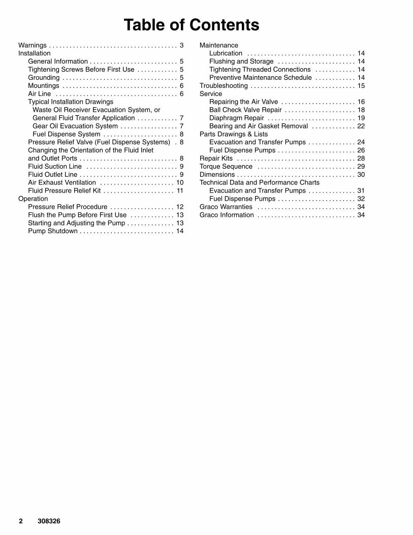
Table of ContentsWarnings 3. . . . . . . . . . . . . . . . . . . . . . . . . . . . . . . . . . . . . . Installation
General Information 5. . . . . . . . . . . . . . . . . . . . . . . . . . Tightening Screws Before First Use 5. . . . . . . . . . . . Grounding 5. . . . . . . . . . . . . . . . . . . . . . . . . . . . . . . . . . Mountings 6. . . . . . . . . . . . . . . . . . . . . . . . . . . . . . . . . . Air Line 6. . . . . . . . . . . . . . . . . . . . . . . . . . . . . . . . . . . . Typical Installation Drawings
Waste Oil Receiver Evacuation System, orGeneral Fluid Transfer Application 7. . . . . . . . . . . . Gear Oil Evacuation System 7. . . . . . . . . . . . . . . . . Fuel Dispense System 8. . . . . . . . . . . . . . . . . . . . . .
Pressure Relief Valve (Fuel Dispense Systems) 8. Changing the Orientation of the Fluid Inlet and Outlet Ports 8. . . . . . . . . . . . . . . . . . . . . . . . . . . . . Fluid Suction Line 9. . . . . . . . . . . . . . . . . . . . . . . . . . . Fluid Outlet Line 9. . . . . . . . . . . . . . . . . . . . . . . . . . . . . Air Exhaust Ventilation 10. . . . . . . . . . . . . . . . . . . . . . Fluid Pressure Relief Kit 11. . . . . . . . . . . . . . . . . . . . .
OperationPressure Relief Procedure 12. . . . . . . . . . . . . . . . . . . Flush the Pump Before First Use 13. . . . . . . . . . . . . Starting and Adjusting the Pump 13. . . . . . . . . . . . . . Pump Shutdown 14. . . . . . . . . . . . . . . . . . . . . . . . . . . .
MaintenanceLubrication 14. . . . . . . . . . . . . . . . . . . . . . . . . . . . . . . . Flushing and Storage 14. . . . . . . . . . . . . . . . . . . . . . . Tightening Threaded Connections 14. . . . . . . . . . . . Preventive Maintenance Schedule 14. . . . . . . . . . . .
Troubleshooting 15. . . . . . . . . . . . . . . . . . . . . . . . . . . . . . . Service
Repairing the Air Valve 16. . . . . . . . . . . . . . . . . . . . . . Ball Check Valve Repair 18. . . . . . . . . . . . . . . . . . . . . Diaphragm Repair 19. . . . . . . . . . . . . . . . . . . . . . . . . . Bearing and Air Gasket Removal 22. . . . . . . . . . . . .
Parts Drawings & ListsEvacuation and Transfer Pumps 24. . . . . . . . . . . . . . Fuel Dispense Pumps 26. . . . . . . . . . . . . . . . . . . . . . .
Repair Kits 28. . . . . . . . . . . . . . . . . . . . . . . . . . . . . . . . . . . Torque Sequence 29. . . . . . . . . . . . . . . . . . . . . . . . . . . . . Dimensions 30. . . . . . . . . . . . . . . . . . . . . . . . . . . . . . . . . . . Technical Data and Performance Charts
Evacuation and Transfer Pumps 31. . . . . . . . . . . . . . Fuel Dispense Pumps 32. . . . . . . . . . . . . . . . . . . . . . .
Graco Warranties 34. . . . . . . . . . . . . . . . . . . . . . . . . . . . . Graco Information 34. . . . . . . . . . . . . . . . . . . . . . . . . . . . .
308326 3
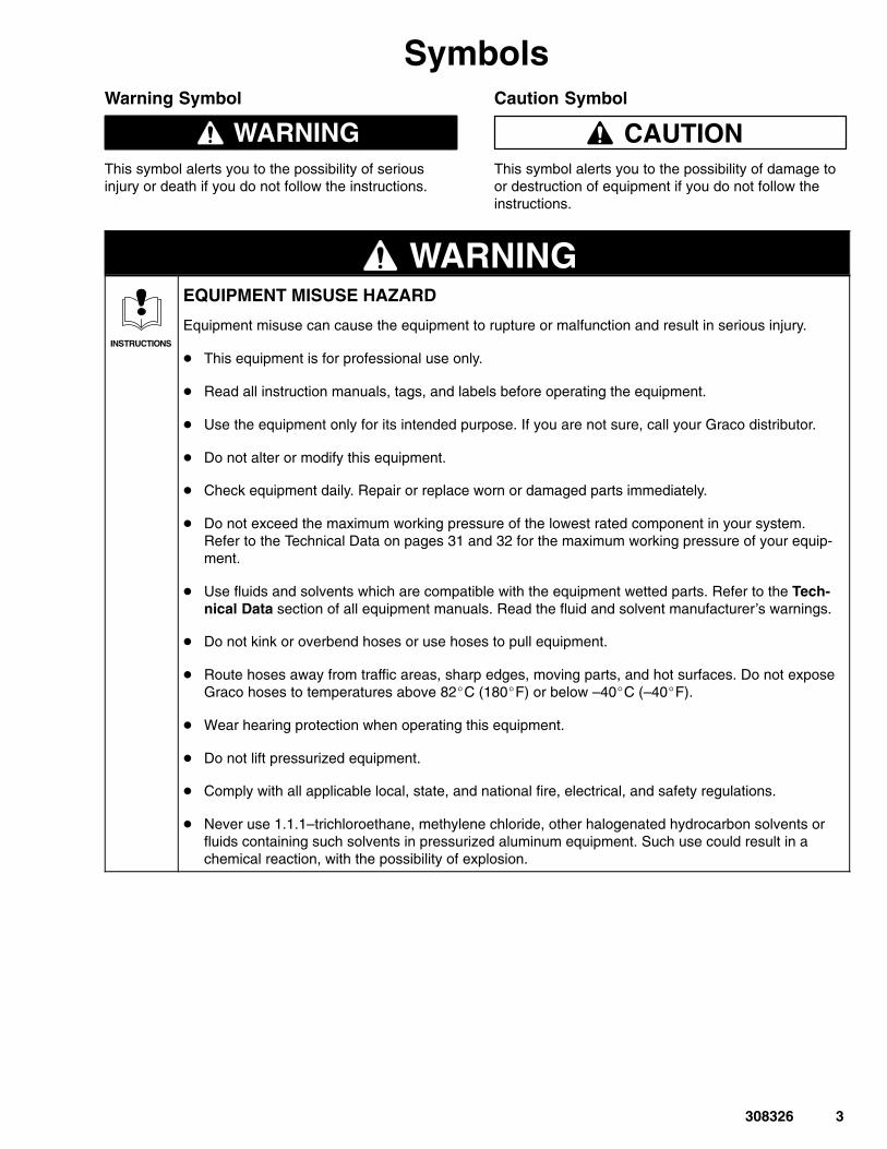
SymbolsWarning Symbol
WARNINGThis symbol alerts you to the possibility of seriousinjury or death if you do not follow the instructions.
Caution Symbol
CAUTIONThis symbol alerts you to the possibility of damage toor destruction of equipment if you do not follow theinstructions.
WARNING
INSTRUCTIONS
EQUIPMENT MISUSE HAZARD
Equipment misuse can cause the equipment to rupture or malfunction and result in serious injury.
� This equipment is for professional use only.
� Read all instruction manuals, tags, and labels before operating the equipment.
� Use the equipment only for its intended purpose. If you are not sure, call your Graco distributor.
� Do not alter or modify this equipment.
� Check equipment daily. Repair or replace worn or damaged parts immediately.
� Do not exceed the maximum working pressure of the lowest rated component in your system.Refer to the Technical Data on pages 31 and 32 for the maximum working pressure of your equip-ment.
� Use fluids and solvents which are compatible with the equipment wetted parts. Refer to the Tech-nical Data section of all equipment manuals. Read the fluid and solvent manufacturer’s warnings.
� Do not kink or overbend hoses or use hoses to pull equipment.
� Route hoses away from traffic areas, sharp edges, moving parts, and hot surfaces. Do not exposeGraco hoses to temperatures above 82�C (180�F) or below –40�C (–40�F).
� Wear hearing protection when operating this equipment.
� Do not lift pressurized equipment.
� Comply with all applicable local, state, and national fire, electrical, and safety regulations.
� Never use 1.1.1–trichloroethane, methylene chloride, other halogenated hydrocarbon solvents orfluids containing such solvents in pressurized aluminum equipment. Such use could result in achemical reaction, with the possibility of explosion.

4 308326
WARNINGTOXIC FLUID HAZARD
Hazardous fluid or toxic fumes can cause serious injury or death if splashed in the eyes or on the skin,inhaled, or swallowed.
� Know the specific hazards of the fluid you are using.
� Store hazardous fluid in an approved container. Dispose of hazardous fluid according to all local,state and national guidelines.
� Always wear protective eyewear, gloves, clothing and respirator as recommended by the fluid andsolvent manufacturer.
� Pipe and dispose of the exhaust air safely, away from people, animals, and food handling areas. Ifthe diaphragm fails, the fluid is exhausted along with the air. See Air Exhaust Ventilation on page10.
� Never use an acetal pump to pump acids. Take precautions to avoid acid or acid fumes fromcontacting the pump housing exterior. Stainless steel parts will be damaged by exposure to acidspills and fumes.
FIRE AND EXPLOSION HAZARD
Improper grounding, poor ventilation, open flames or sparks can cause a hazardous condition andresult in a fire or explosion and serious injury.
� Ground the equipment. Refer to Grounding on page 5.
� If there is any static sparking or you feel an electric shock while using this equipment, stop pump-ing immediately. Do not use the equipment until you identify and correct the problem.
� Provide fresh air ventilation to avoid the buildup of flammable fumes from solvents or the fluidbeing pumped.
� Pipe and dispose of the exhaust air safely, away from all sources of ignition. If the diaphragm fails,the fluid is exhausted along with the air. See Air Exhaust Ventilation on page 10.
� Keep the work area free of debris, including solvent, rags, and gasoline.
� Electrically disconnect all equipment in the work area.
� Extinguish all open flames or pilot lights in the work area.
� Do not smoke in the work area.
� Do not turn on or off any light switch in the work area while operating or if fumes are present.
� Do not operate a gasoline engine in the work area.
� Keep a fire extinguisher in the work area.

308326 5
InstallationGeneral Information
� The Typical Installations shown in Figs. 2 to 4 areonly guides for selecting and installing systemcomponents. Contact your Graco distributor orGraco Technical Assistance (see back page) forassistance in planning a system to suit your needs.
� Reference numbers and letters in parentheses referto the callouts in the figures and the parts lists onpages 24 to 27.
� Installation and use must be in accordance with theFlammable and Combustible Liquids Code (NFPA30) and Automotive and Marine Service StationCode (NFPA 30A) and must comply with all local,state and federal codes.
� All pipe joints are to be made tight with UL listedgasoline–resistant pipe compound.
Tightening Screws Before First Use
Before using the pump for the first time, check andretorque all external fasteners. See TorqueSequence, page 29. After the first day of operation,retorque the fasteners. Although pump use varies, ageneral guideline is to retorque fasteners every twomonths.
Grounding
WARNINGFIRE AND EXPLOSION HAZARDBefore operating the pump, ground thesystem as explained below. Also readthe section FIRE AND EXPLOSIONHAZARD on page 4.
� Pump: loosen the grounding screw (W). Insert oneend of a 12 ga (1.5 mm2) minimum ground wire (Y)behind the grounding screw and tighten the screwsecurely. See Fig. 1. Connect the clamp end of theground wire to a true earth ground. Order Part No.222011 Ground Wire and Clamp.
� Air and fluid hoses: use only grounded hoses with amaximum of 500 ft (150 m) combined hose lengthto ensure grounding continuity.
� Air compressor: follow manufacturer’srecommendations.
� All solvent pails used when flushing, according tolocal code. Use only metal pails, which areconductive. Do not place the pail on anon-conductive surface, such as paper orcardboard, which interrupts the groundingcontinuity.
� Fluid supply container: according to local code.
� Suction device nozzle: must be bonded to metalcontainer from which it is suctioning by firmmetal-to-metal contact to a properly groundedsuction hose and pump.
� Piping, valves, and fittings: use only electricallyconductive materials. Bond and ground per code.
Check your system electrical continuity after the initialinstallation, and then set up a regular schedule forchecking continuity to be sure proper grounding ismaintained.
02646B
Fig. 1
Y
W

6 308326
InstallationMountings
CAUTIONThe pump exhaust air may contain contaminants.Ventilate to a remote area if the contaminants couldaffect your fluid supply. See Air Exhaust Ventilationon page 10.
� Be sure the mounting surface can support theweight of the pump, hoses, and accessories, aswell as the stress caused during operation.
� For all mountings, be sure the pump is bolteddirectly to the mounting surface.
� For ease of operation and service, mount the pumpso the air valve cover (7), air inlet, and fluid inletand outlet ports are easily accessible.
� Rubber Foot Mounting Kit 236452 is available toreduce noise and vibration during operation.Contact your Graco distributor.
WARNINGTo reduce the risk of serious injury, splashing in theeyes or on the skin, and toxic fluid spills, nevermove or lift a pump under pressure. If dropped, thefluid section may rupture. Always follow the Pres-sure Relief Procedure Warning on page 12before moving or lifting the pump.
Air Line
WARNINGA bleed-type master air valve (B) is required in yoursystem to relieve air trapped between this valveand the pump. Trapped air can cause the pump tocycle unexpectedly, which could result in seriousinjury, including splashing in the eyes or on theskin, injury from moving parts, or contaminationfrom hazardous fluids.
1. Install the air line accessories as shown in Figs.2 to 4 on pages 7 and 8. Mount theseaccessories on the wall or on a bracket. Be surethe air line supplying the accessories is grounded.
a. Install an air regulator (C) and gauge to controlthe fluid pressure. The fluid outlet pressure atstall will be the same as the setting of the airregulator.
b. Locate one bleed-type master air valve (B)close to the pump and use it to relieve trappedair. See the WARNING above. Locate theother master air valve (E) upstream from all airline accessories and use it to isolate themduring cleaning and repair.
c. The air line filter (F) removes harmful dirt andmoisture from the compressed air supply.
2. Install a grounded, flexible air hose (A) betweenthe accessories and the 1/2 npt(f) pump air inlet(N). See Fig. 5. Use a minimum 1/2” (13 mm) IDair hose. Screw an air line quick disconnectcoupler (D) onto the end of the air hose (A), andscrew the mating fitting into the pump air inletsnugly. Do not connect the coupler (D) to the fittinguntil you are ready to operate the pump.
308326 7
Installation
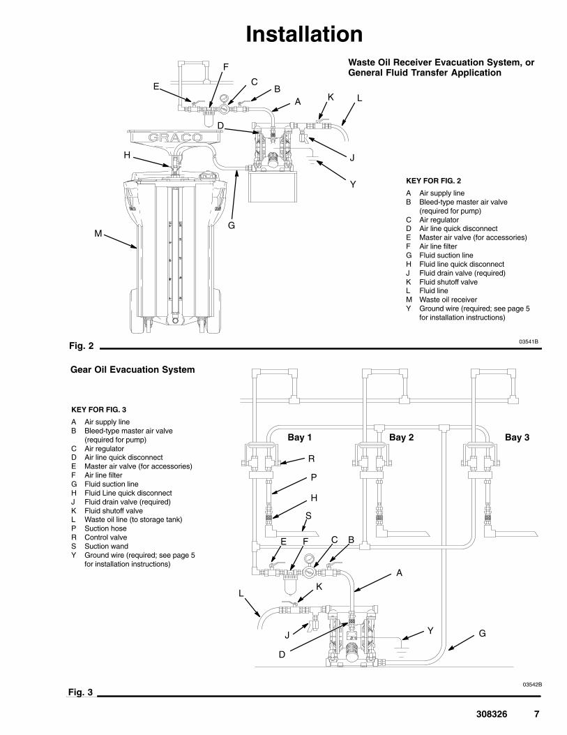
KEY FOR FIG. 2
A Air supply lineB Bleed-type master air valve
(required for pump)C Air regulatorD Air line quick disconnectE Master air valve (for accessories)F Air line filterG Fluid suction lineH Fluid line quick disconnectJ Fluid drain valve (required)K Fluid shutoff valveL Fluid lineM Waste oil receiverY Ground wire (required; see page 5
for installation instructions)
Fig. 2
Waste Oil Receiver Evacuation System, orGeneral Fluid Transfer Application
J
F
BE C
A
D
G
H
K L
M
Y
03541B
KEY FOR FIG. 3
A Air supply lineB Bleed-type master air valve
(required for pump)C Air regulatorD Air line quick disconnectE Master air valve (for accessories)F Air line filterG Fluid suction lineH Fluid Line quick disconnectJ Fluid drain valve (required)K Fluid shutoff valveL Waste oil line (to storage tank)P Suction hoseR Control valveS Suction wandY Ground wire (required; see page 5
for installation instructions)
03542B
Fig. 3
Gear Oil Evacuation System
YJ
F BE C
A
D
KL
G
H
P
R
Bay 1 Bay 2 Bay 3
S
8 308326
Installation
03543B
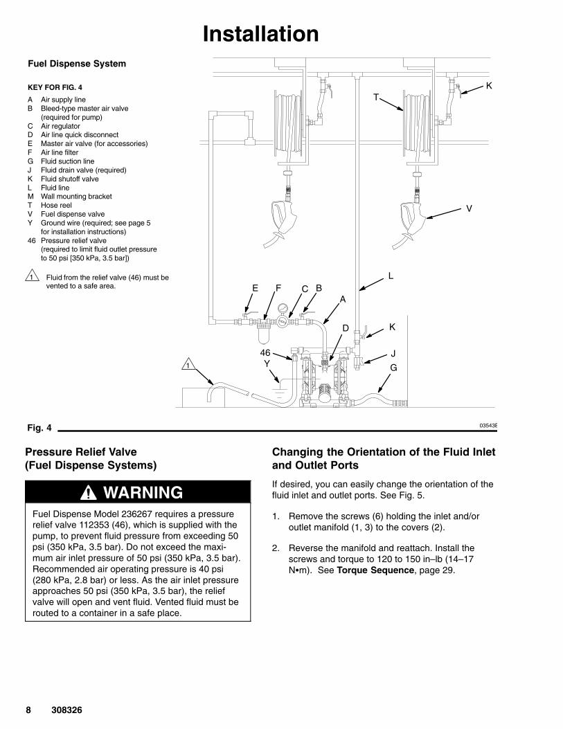
KEY FOR FIG. 4
A Air supply lineB Bleed-type master air valve
(required for pump)C Air regulatorD Air line quick disconnectE Master air valve (for accessories)F Air line filterG Fluid suction lineJ Fluid drain valve (required)K Fluid shutoff valveL Fluid lineM Wall mounting bracketT Hose reelV Fuel dispense valveY Ground wire (required; see page 5
for installation instructions)46 Pressure relief valve
(required to limit fluid outlet pressure to 50 psi [350 kPa, 3.5 bar])
Fig. 4
Fuel Dispense System
Y
F BE CA
D
G
K
L
T
V
K
46
1 Fluid from the relief valve (46) must bevented to a safe area.
1
J
Pressure Relief Valve(Fuel Dispense Systems)
WARNINGFuel Dispense Model 236267 requires a pressurerelief valve 112353 (46), which is supplied with thepump, to prevent fluid pressure from exceeding 50psi (350 kPa, 3.5 bar). Do not exceed the maxi-mum air inlet pressure of 50 psi (350 kPa, 3.5 bar).Recommended air operating pressure is 40 psi(280 kPa, 2.8 bar) or less. As the air inlet pressureapproaches 50 psi (350 kPa, 3.5 bar), the reliefvalve will open and vent fluid. Vented fluid must berouted to a container in a safe place.
Changing the Orientation of the Fluid Inletand Outlet Ports
If desired, you can easily change the orientation of thefluid inlet and outlet ports. See Fig. 5.
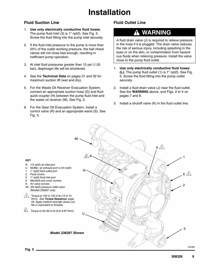
1. Remove the screws (6) holding the inlet and/oroutlet manifold (1, 3) to the covers (2).
2. Reverse the manifold and reattach. Install thescrews and torque to 120 to 150 in–lb (14–17N�m). See Torque Sequence, page 29.
308326 9
InstallationFluid Suction Line
1. Use only electrically conductive fluid hoses.The pump fluid inlet (3) is 1” npt(f). See Fig. 5.Screw the fluid fitting into the pump inlet securely.
2. If the fluid inlet pressure to the pump is more than25% of the outlet working pressure, the ball checkvalves will not close fast enough, resulting ininefficient pump operation.
3. At inlet fluid pressures greater than 15 psi (1.05bar), diaphragm life will be shortened.
4. See the Technical Data on pages 31 and 32 formaximum suction lift (wet and dry).
5. For the Waste Oil Receiver Evacuation System,connect an appropriate suction hose (G) and fluidquick coupler (H) between the pump fluid inlet andthe waste oil receiver (M). See Fig. 2.
6. For the Gear Oil Evacuation System, install acontrol valve (R) and an appropriate wand (S). SeeFig. 3.
Fluid Outlet Line
WARNINGA fluid drain valve (J) is required to relieve pressurein the hose if it is plugged. The drain valve reducesthe risk of serious injury, including splashing in theeyes or on the skin, or contamination from hazard-ous fluids when relieving pressure. Install the valveclose to the pump fluid outlet.
1. Use only electrically conductive fluid hoses(L). The pump fluid outlet (1) is 1” npt(f). See Fig.5. Screw the fluid fitting into the pump outletsecurely.
2. Install a fluid drain valve (J) near the fluid outlet.See the WARNING above, and Figs. 2 to 4 onpages 7 and 8.
3. Install a shutoff valve (K) in the fluid outlet line.
03538BFig. 5
1
2
Torque to 120 to 150 in-lb (14 to 15N�m). See Torque Sequence, page29. Apply medium-strength (blue) Loc-tite or equivalent to threads.
KEY
N 1/2 npt(f) air inlet portU Muffler; air exhaust port is 3/4 npt(f)1 1” npt(f) fluid outlet port2 Fluid covers3 1” npt(f) fluid inlet port6 Manifold and cover screws8 Air valve screws46 3/8 npt(f) pressure relief valve
(Models 236267 only)
N
3
1
Torque to 50–60 in-lb (5.6–6.87 N�m).
8
6 1
2
Model 236267 Shown
6 1
46
U
2
10 308326
InstallationAir Exhaust Ventilation
WARNINGBe sure to read and follow the TOXIC FLUIDHAZARD and FIRE AND EXPLOSION HAZARDwarnings on page 4 before operating this pump.
Be sure the system is properly ventilated for yourtype of installation. You must vent the exhaust to asafe place, away from people, animals, food han-dling area, and all sources of ignition when pump-ing flammable or hazardous fluids.
Diaphragm failure will cause the fluid beingpumped to exhaust with the air. Place an appropri-ate container at the end of the air exhaust line tocatch the fluid. See Fig. 6.
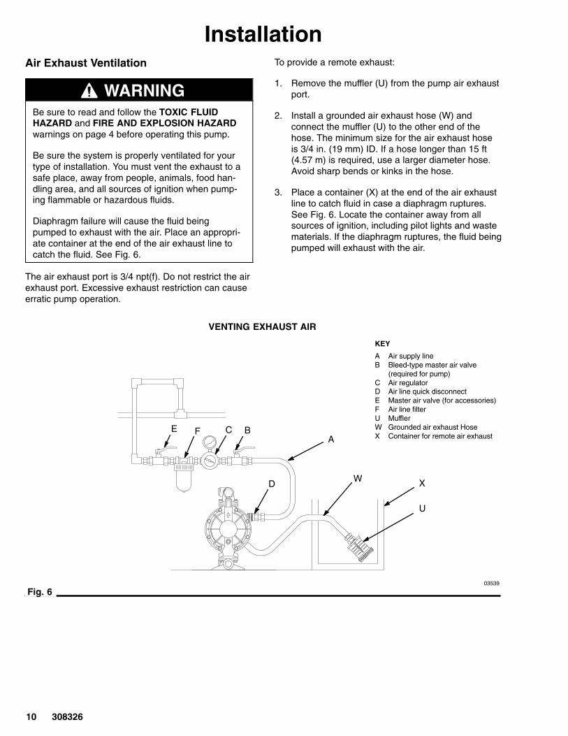
The air exhaust port is 3/4 npt(f). Do not restrict the airexhaust port. Excessive exhaust restriction can causeerratic pump operation.
To provide a remote exhaust:
1. Remove the muffler (U) from the pump air exhaustport.
2. Install a grounded air exhaust hose (W) andconnect the muffler (U) to the other end of thehose. The minimum size for the air exhaust hoseis 3/4 in. (19 mm) ID. If a hose longer than 15 ft(4.57 m) is required, use a larger diameter hose.Avoid sharp bends or kinks in the hose.
3. Place a container (X) at the end of the air exhaustline to catch fluid in case a diaphragm ruptures.See Fig. 6. Locate the container away from allsources of ignition, including pilot lights and wastematerials. If the diaphragm ruptures, the fluid beingpumped will exhaust with the air.
03539
Fig. 6
KEY
A Air supply lineB Bleed-type master air valve
(required for pump)C Air regulatorD Air line quick disconnectE Master air valve (for accessories)F Air line filterU MufflerW Grounded air exhaust HoseX Container for remote air exhaustF BE C
A
D
VENTING EXHAUST AIR
U
W X

308326 11
InstallationFluid Pressure Relief Kit (for Pump Model236265 only)
Pressure Relief Kit 238428 (Z) is available, to pre-vent overpressurization and rupture of the pump orhose. See Fig. 7. The kit includes instructions.
This kit is not for use in fuel dispense applica-tions. Order a fuel dispense pump, Model 236267,which is equipped with a pressure relief valve112353. See page 8.
Thermal expansion of fluid in the outlet line cancause overpressurization. This can occur when usinglong fluid lines exposed to sunlight or ambient heat,or when pumping from a cool to a warm area (forexample, from an underground tank).
Overpressurization can also occur if the Husky pumpis being used to feed fluid to a piston pump, and theintake valve of the piston pump does not close,causing fluid to back up in the outlet line.
CAUTION
Fig. 7
1
2 Connect fluid inlet line here.
KEY
1 1” npt(f) Optional fluid outlet port3 1” npt(f) Optional fluid inlet portZ Pressure relief kit
3
1
Connect fluid outlet line here.
1
2
3
Apply medium-strength (blue) Loctite or equivalent to the threads. andinstall kit between fluid inlet andoutlet manifolds.
Z
3
For Model 236265
02653C
12 308326
OperationPressure Relief Procedure
PRESSURIZED EQUIPMENT HAZARDThe equipment stays pressurized until pressure ismanually relieved. To reduce the risk of seriousinjury from pressurized fluid, accidental spray fromthe gun or splashing fluid, follow this procedurewhenever you
� Are instructed to relieve pressure� Stop pumping� Check, clean or service any system equipment� Install or clean fluid nozzles
WARNING
1. Shut off the air to the pump.
2. Open the dispensing valve, if used.
3. Open the fluid drain valve to relieve all fluidpressure, having a container ready to catch thedrainage.

308326 13
Flush the Pump Before First Use
The pump was tested with lightweight oil, which is leftin the fluid passages to protect parts. To avoidcontaminating your fluid with oil, flush the pump with acompatible solvent before using the equipment. Followthe steps under Starting and Adjusting the Pump.
Starting and Adjusting the Pump
All Systems
WARNINGTo reduce the risk of serious injury, splashing in theeyes or on the skin, and toxic fluid spills, nevermove or lift a pump under pressure. If dropped, thefluid section may rupture. Always follow the Pres-sure Relief Procedure Warning on page 12before moving or lifting the pump.
1. Be sure the pump is properly grounded. Read andfollow FIRE AND EXPLOSION HAZARD, on page4.
2. Check all fittings to be sure they are tight. Be sureto use a compatible liquid thread sealant on allmale threads. Tighten the fluid inlet and outletfittings securely.
NOTE: If the fluid inlet pressure to the pump is morethan 25 percent of the outlet working pressure, the ballcheck valves will not close fast enough, resulting ininefficient pump operation.
NOTE: If you are flushing, run the pump long enoughto thoroughly clean the pump and hoses. Close the airregulator. Remove the suction tube from the solventand place it in the fluid to be pumped.
Waste OIl Receiver Evacuation Systems, orGeneral Fluid Transfer Applications (see Fig. 2)
1. Close the pump air regulator (C) and all bleed-typemaster air valves (B, E).
2. Connect the pump suction hose (G) to the pumpfluid inlet. Attach a fluid quick coupler (H) to theother end of the hose, then connect the coupler tothe outlet fitting of the waste oil receiver (M).
3. Place the end of the fluid hose (L) into anappropriate container.
4. Close the fluid drain valve (J). Open the fluidshutoff valve (K).
5. Connect the air side quick coupler (D) to the pumpair inlet fitting.
6. Open all bleed-type master air valves (B, E).
7. Slowly increase air with the air regulator (C) untilthe pump starts to cycle. Allow the pump to cycleslowly until all air is pushed out of the lines and thepump is primed.
8. Adjust the air regulator. Do not use higher airpressure than necessary for the pump to providegood suction. Increasing the pump cycle rate doesnot necessarily improve suction.
Gear Oil Evacuation Systems (see Fig. 3)
1. Close the pump air regulator (C) and all bleed-typemaster air valves (B, E).
2. Attach an appropriate wand (S) to the suction hose(P). Place the wand in the differential or fluid to bepumped.
3. Place the end of the fluid hose (L) into anappropriate container.
4. Close the fluid drain valve (J). Open the fluidshutoff valve (K).
5. Connect the air side quick coupler (D) to the pumpair inlet fitting.
6. Open all bleed-type master air valves (B, E).
7. Set the air regulator (C) to about 50 psi (3.5 bar).
8. Pull the control valve handle (R) down to start thepump.
9. Adjust the air regulator. Allow the pump to cycleslowly until all air is pushed out of the lines and thepump is primed. Do not use higher air pressurethan necessary for the pump to provide goodsuction. Increasing the pump cycle rate does notnecessarily improve suction.
NOTE: To provide better control of the cycle rate,order Air Supply Kit 221147.
10. Push the control valve handle (R) up whenfinished. Place the wand (S) in the holder on thecontrol valve.
NOTE: Be sure the control valve handle is closedwhen evacuation is completed. Failure to close it mayprevent other service bays from developing fullsuction.

14 308326
OperationFuel Dispense Systems (see Fig. 4)
WARNINGFuel Dispense Model 236267 requires a pressurerelief valve (46), which is supplied with the pump,to prevent fluid pressure from exceeding 50 psi(350 kPa, 3.5 bar). Do not exceed the maximum airinlet pressure of 50 psi (350 kPa, 3.5 bar). Recom-mended air operating pressure is 40 psi (280 kPa,2.8 bar) or less. As the air inlet pressure ap-proaches 50 psi (350 kPa, 3.5 bar), the relief valvewill open and vent fluid. Vented fluid must berouted to a container in a safe place.
1. Close the pump air regulator (C) and all bleed-typemaster air valves (B, E).
2. Close the fluid drain valve (J). Open the fluidshutoff valve (K).
3. Hold the dispense valve (V) firmly to a groundedmetal container, and open the valve.
4. Connect the air side quick coupler (D) to the pumpair inlet fitting.
5. Open all bleed-type master air valves (B, E).
6. Slowly open the air regulator (C) until the pumpstarts to cycle. Allow the pump to cycle slowly untilall air is pushed out of the lines and the pump isprimed.
7. Adjust the air regulator. Do not use higher airpressure than necessary for the pump to providegood suction. Increasing the pump cycle rate doesnot necessarily improve suction.
Pump Shutdown (All Systems)
WARNINGTo reduce the risk of serious injury whenever youare instructed to relieve pressure, always follow thePressure Relief Procedure on page 12.
At the end of the work shift and before checking,adjusting, cleaning or repairing the system, relieve thepressure.
MaintenanceLubrication
The air valve is designed to operate unlubricated,however if lubrication is desired, every 500 hours ofoperation (or monthly) remove the hose from the pumpair inlet and add two drops of machine oil to the airinlet.
CAUTIONDo not over-lubricate the pump. Oil is exhaustedthrough the muffler, which could contaminate yourfluid supply or other equipment. Excessive lubricationcan also cause the pump to malfunction.
An air line lubricator is available, contact your Gracodistributor for more information.
Flushing and Storage
WARNINGTo reduce the risk of serious injury whenever youare instructed to relieve pressure, always follow thePressure Relief Procedure on page 12.
Flush the pump often enough to prevent the fluid youare pumping from drying or freezing in the pump anddamaging it. Always flush the pump and relieve thepressure before storing it for any length of time. Use acompatible solvent.
Tightening Threaded Connections
Before each use, check all hoses for wear or damage,and replace as necessary. Check to be sure allthreaded connections are tight and leak free. Checkfasteners. Tighten or retorque as necessary. Althoughpump use varies, a general guideline is to retorquefasteners every two months. See Torque Sequence,page 29.
Preventive Maintenance Schedule
Establish a preventive maintenance schedule, basedon the pump’s service history. This is especiallyimportant for prevention of spills or leakage due todiaphragm failure.

308326 15
Troubleshooting
WARNINGTo reduce the risk of serious injury whenever youare instructed to relieve pressure, always follow thePressure Relief Procedure on page 12.
Relieve the pressure before you check or service anysystem equipment.
Check all possible problems and solutions beforedisassembling the motor.
PROBLEM CAUSE SOLUTION
Pump cycles at stall or fails to hold pres-sure at stall.
Worn check valve balls (16) or seats(17).
Replace. See page 18.
Pump will not cycle, or cycles once andstops.
Air valve is stuck or dirty. Disassemble and clean air valve. Seepages 16 and 17. Use filtered air.
Check valve ball (16) severely worn andwedged in seat (17) or manifold (1 or 3).
Replace ball and seat. See page 18.
Check valve ball (16) is wedged intoseat (17), due to overpressurization.
Install Pressure Relief Kit (see page 11).
Dispensing valve clogged. Relieve pressure and clear valve.
Pump operates erratically. Clogged suction line. Inspect; clear.
Sticky or leaking check valve balls (16). Clean or replace. See page 18.
Diaphragm (29) ruptured. Replace. See pages 19 to 21.
Restricted exhaust. Remove restriction.
Pump will not operate. Foreign material in ball checks. Clean ball check area.
Air bubbles in fluid. Suction line is loose. Tighten.
Diaphragm (29) ruptured. Replace. See pages 19 to 21.
Loose manifolds (1, 3), or damaged sealbetween manifold and seat (17).
Tighten manifold bolts (6) or replaceseats (17). See page 18.
Loose diaphragm shaft bolt (21). Tighten. See pages 19 to 21.
Damaged o-ring (25). Replace. See pages 19 to 21.
Fluid in exhaust air. Diaphragm (29) ruptured. Replace. See pages 19 to 21.
Loose diaphragm shaft bolt (21). Tighten. See pages 19 to 21.
Damaged o-ring (25). Replace. See pages 19 to 21.
Pump exhausts excessive air at stall. Worn air valve block (13), o-ring (12),plate (14), pilot block (9), or o-ring (27).
Repair or replace. See pages 16 and17.
Worn shaft seals (22). Replace. See pages 19 to 21.
Pump leaks air externally. Air valve cover (7) or air valve coverscrews (8) are loose.
Tighten screws. See page 17.
Air valve gasket (10) or air cover gasket(32) is damaged.
Inspect; replace. See pages 16 and 17,22 and 23.
Air cover screws (6) are loose. Tighten screws. See pages 22 and 23.
Pump leaks fluid externally from ballcheck valves.
Loose manifolds (1, 3), or damaged sealbetween manifold and seat (17).
Tighten manifold bolts (6) or replaceseats (17). See page 18.
Relief valve relieving (Fuel DispenseModel 236267).
Air inlet pressure is too high. Reduce inlet air pressure to below 50psi (3.5 bar).
In evacuation application, pump is notdrawing suction.
Pump should run at uniform speed. Reduce inlet air pressure or use AirSupply Kit 221147.
16 308326
ServiceRepairing the Air Valve
Tools Required
� Torque wrench
� Torx (T20) screwdriver or 7 mm (9/32”) socketwrench
� Needle-nose pliers
� O-ring pick
� Lithium base grease
NOTE: Air Valve Repair Kit 236273 is available. Referto page 28. Parts included in the kit are marked with asymbol, for example (10�). Use all the parts in the kitfor the best results.
Disassembly
WARNINGTo reduce the risk of serious injury whenever youare instructed to relieve pressure, always follow thePressure Relief Procedure on page 12.
1. Relieve the pressure.
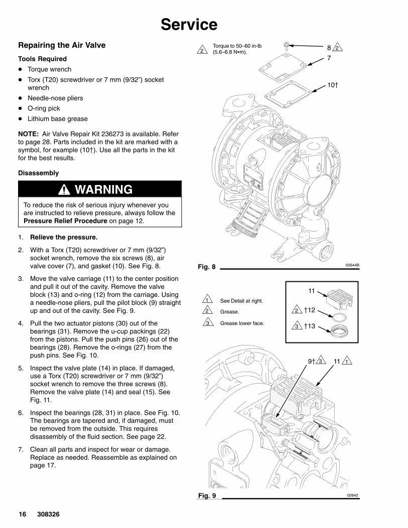
2. With a Torx (T20) screwdriver or 7 mm (9/32”)socket wrench, remove the six screws (8), airvalve cover (7), and gasket (10). See Fig. 8.
3. Move the valve carriage (11) to the center positionand pull it out of the cavity. Remove the valveblock (13) and o-ring (12) from the carriage. Usinga needle-nose pliers, pull the pilot block (9) straightup and out of the cavity. See Fig. 9.
4. Pull the two actuator pistons (30) out of thebearings (31). Remove the u-cup packings (22)from the pistons. Pull the push pins (26) out of thebearings (28). Remove the o-rings (27) from thepush pins. See Fig. 10.
5. Inspect the valve plate (14) in place. If damaged,use a Torx (T20) screwdriver or 7 mm (9/32”)socket wrench to remove the three screws (8).Remove the valve plate (14) and seal (15). SeeFig. 11.
6. Inspect the bearings (28, 31) in place. See Fig. 10.The bearings are tapered and, if damaged, mustbe removed from the outside. This requiresdisassembly of the fluid section. See page 22.
7. Clean all parts and inspect for wear or damage.Replace as needed. Reassemble as explained onpage 17.
Torque to 50–60 in-lb (5.6–6.8 N�m).
Fig. 8
8
7
10�
2 2
02644B
9� 11
Fig. 9
1
2
See Detail at right.
Grease.
3 Grease lower face.
1
�13
�12
11
2
3
02642
3

308326 17
Service
02643Fig. 10
27� 26
30
22�
31
28
1
2
Insert narrow end first.
Grease.
3Install with lips facing narrow end of piston (30).
4 Insert wide end first.
12
3
4
2
02645
1
2
14
�15
8Rounded side must face down.
Torque to 50–60 in-lb (5.6–6.8 N�m).
Fig. 11
1
2
Reassembly
1. If you replaced the bearings (28, 31), reinstall asexplained on page 22. Reassemble the fluidsection.
2. Install the valve plate seal (15�) into the groove atthe bottom of the valve cavity. The rounded side ofthe seal must face down into the groove. SeeFig. 11.
3. Install the valve plate (14) in the cavity. The plateis reversible, so either side can face up. Install thethree screws (8), using a Torx (T20) screwdriver or7 mm (9/32”) socket wrench. Torque to 50–60 in-lb(5.6–6.8 N�m). See Fig. 11.
4. Install an o-ring (27�) on each push pin (26).Grease the pins and o-rings. Insert the pins intothe bearings (28), narrow end first. See Fig. 10.
5. Install a u-cup packing (22�) on each actuatorpiston (30), so the lips of the packings face thenarrow end of the pistons. See Fig. 10.
6. Lubricate the u-cup packings (22�) and actuatorpistons (30). Insert the actuator pistons in thebearings (31), wide end first. Leave the narrowend of the pistons exposed. See Fig. 10.
7. Install the pilot block (9�) so its tabs snap into thegrooves on the ends of the push pins (26). SeeFig. 9.
8. Grease the o-ring (12�) and install it in the valveblock (13). Push the block onto the valve carriage(11). Grease the lower face of the valve block. SeeFig. 9.
9. Align the valve carriage (11) with the actuatorpistons (30) and install so its tabs slip into thegrooves on the narrow end of the pistons. See Fig.9.
10. Align the valve gasket (10�) and cover (7) with thesix holes in the center housing (5). Secure with sixscrews (8), using a Torx (T20) screwdriver or 7mm (9/32”) socket wrench. Torque to 50–60 in-lb(5.6–6.8 N�m). See Fig. 8.

18 308326
ServiceBall Check Valve Repair
Tools Required
� Torque wrench
� 10 mm socket wrench
� O-ring pick
Disassembly
WARNINGTo reduce the risk of serious injury whenever youare instructed to relieve pressure, always follow thePressure Relief Procedure on page 12.
NOTE: A Fluid Section Repair Kit is available. Refer topage 28 to order the correct kit for your pump. Partsincluded in the kit are marked with an asterisk, forexample (16*). Use all the parts in the kit for the bestresults.
NOTE: To ensure proper seating of the balls (16),always replace the seats (17) when replacing the balls.
1. Relieve the pressure. Disconnect all hoses.
2. Remove the pump from its mounting.
3. Using a 10 mm socket wrench, remove the fourbolts (6) holding the outlet manifold (1) to the fluidcovers (2). See Fig. 12.
4. Remove the seats (17) and balls (16) from themanifold.
5. Turn the pump over and remove the inlet manifold(3). Remove the seats (17) and balls (16) from thefluid covers (2).
Reassembly
1. Clean all parts and inspect for wear or damage.Replace parts as needed.
2. Reassemble in the reverse order, following allnotes in Fig. 12. Be sure the ball checks areassembled exactly as shown. The arrows (A) onthe fluid covers (2) must point toward the outletmanifold (1).
03540BFig. 12
1
2
Apply medium-strength (blue) Loctite or equivalent to thethreads, and torque to 120 to 150 in-lb (14 to 17 N�m). SeeTorque Sequence, page 29.
Arrow (A) must point toward outlet manifold (1).
6
1
2
A
17*
16*
6
3
17*
16*
2
1
1
Model 236267 Shown

308326 19
ServiceDiaphragm Repair
Tools Required
� Torque wrench
� 10 mm socket wrench
� 15 mm socket wrench
� O-ring pick
� Lithium-base grease
Disassembly
WARNINGTo reduce the risk of serious injury whenever youare instructed to relieve pressure, always follow thePressure Relief Procedure on page 12.
NOTE: A Fluid Section Repair Kit is available. Refer topage 28 to order the correct kit for your pump. Partsincluded in the kit are marked with an asterisk, forexample (29*). Use all the parts in the kit for the bestresults.
1. Relieve the pressure
2. Remove the manifolds and disassemble the ballcheck valves as explained on page 18.
3. Using a 10 mm socket wrench, remove the screws(6) holding the fluid covers (2) to the air covers (4).Pull the fluid covers (2) off the pump. See Fig. 13.
Fig. 13
1
2
4
2
6
A 2
B
Arrow (A) must point toward air valve (B).
1
Apply medium-strength (blue) Loctite or equivalent tothe threads, and torque to 120 to 150 in-lb (14 to 17N�m). See Torque Sequence, page 29.
02635B
20 308326
Service4. Loosen but do not remove the diaphragm shaft
bolts (21), using a 15 mm socket wrench on bothbolts.
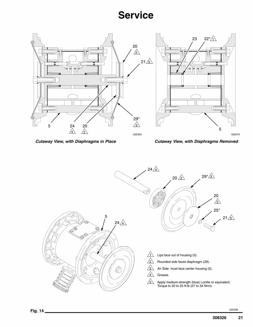
5. Unscrew one bolt from the diaphragm shaft (24)and remove the o-ring (25), fluid side diaphragmplate (20), diaphragm (29), and air side diaphragmplate (20). See Fig. 14.
6. Pull the other diaphragm assembly and thediaphragm shaft (24) out of the center housing (5).Remove the bolt (21) from the shaft anddisassemble the remaining diaphragm assembly.
7. Inspect the diaphragm shaft (24) for wear orscratches. If it is damaged, inspect the bearings(23) in place. If the bearings are damaged, refer topage 22.
8. Reach into the center housing (5) with an o-ringpick and hook the u-cup packings (22), then pullthem out of the housing. This can be done with thebearings (23) in place.
9. Clean all parts and inspect for wear or damage.Replace parts as needed.
Reassembly1. Install the shaft u-cup packings (22*) so the lips
face out of the housing (5). Lubricate thepackings. See Fig. 14.
2. Install the diaphragm assembly on one end of theshaft (24) as follows:
a. Install the o-ring (25*) on the shaft bolt (21).
b. Install the fluid side diaphragm plate (20) onthe bolt so the rounded side faces thediaphragm (29).
c. Install the diaphragm (29*) on the bolt. Makecertain the side marked AIR SIDE faces thecenter housing (5).
d. Install the air side diaphragm plate (20) so therounded side faces the diaphragm (29).
e. Apply medium-strength (blue) Loctite orequivalent to the bolt (21) threads. Screw thebolt (21) into the shaft (24) hand tight.
3. Grease the length and ends of the diaphragm shaft(24), and slide it through the housing (5).
4. Assemble the other diaphragm assembly to theshaft as explained in step 2.
5. Hold one shaft bolt (21) with a wrench and torquethe other bolt to 20 to 25 ft-lb (27 to 34 N�m) at100 rpm maximum.
6. Align the fluid covers (2) and the center housing(5) so the arrows (A) on the covers face the samedirection as the air valve (B). Applymedium-strength (blue) Loctite or equivalent to thethreads of the screws (6), and secure the coverswith the screws (6) hand tight. See Fig. 13. Usinga 10 mm socket wrench, torque the screwsoppositely and evenly to 120 to 150 in-lb (14 to 17N�m). See Torque Sequence, page 29.
7. Reassemble the ball check valves and manifoldsas explained on page 18.
308326 21
Service
03535A
03533BFig. 14
1
3
4
2
24
20 29*
25*
2124
24 20
29*
21
20
23 22*
Cutaway View, with Diaphragms in Place Cutaway View, with Diaphragms Removed
5
Lips face out of housing (5).
Rounded side faces diaphragm (29).
Air Side must face center housing (5).
5
Grease.
Apply medium-strength (blue) Loctite or equivalent.Torque to 20 to 25 ft-lb (27 to 34 N�m).
5
1
2
2
2
3
3
5
4
4
4
5
5
02637A
202
22 308326
ServiceBearing and Air Gasket Removal
Tools Required
� Torque wrench
� 10 mm socket wrench
� Bearing puller
� O-ring pick
� Press, or block and mallet
Disassembly
WARNINGTo reduce the risk of serious injury whenever youare instructed to relieve pressure, always follow thePressure Relief Procedure on page 12.
NOTE: Do not remove undamaged bearings.
1. Relieve the pressure.
2. Remove the manifolds and disassemble the ballcheck valves as explained on page 18.
3. Remove the fluid covers and diaphragmassemblies as explained on page 19.
NOTE: If you are removing only the diaphragm shaftbearing (23), skip step 4.
4. Disassemble the air valve as explained on page16.
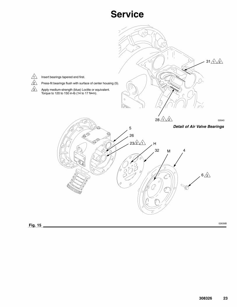
5. Using a 10 mm socket wrench, remove the screws(6) holding the air covers (4) to the center housing(5). See Fig. 15.
6. Remove the air cover gaskets (32). Always replacethe gaskets with new ones.
7. Use a bearing puller to remove the diaphragmshaft bearings (23), air valve bearings (31) or pilotpin bearings (28). Do not remove undamagedbearings.
8. If you removed the diaphragm shaft bearings (23),reach into the center housing (5) with an o-ring pick and hook the u-cup packings (22), thenpull them out of the housing. Inspect the packings.See Fig. 14.
Reassembly1. If removed, install the shaft u-cup packings (22*)
so the lips face out of the housing (5).
2. The bearings (23, 28, and 31) are tapered and canonly be installed one way. Insert the bearings intothe center housing (5), tapered end first. Using apress or a block and rubber mallet, press-fit thebearing so it is flush with the surface of the centerhousing.
3. Reassemble the air valve as explained on page17.
4. Align the new air cover gasket (32) so the pilot pin(26) protruding from the center housing (5) fitsthrough the proper hole (H) in the gasket.
5. Align the air cover (4) so the pilot pin (26) fits inthe middle hole (M) of the three small holes nearthe center of the cover. Apply medium-strength(blue) Loctite or equivalent to the threads of thescrews, and install the screws (6), hand tight. SeeFig. 15. Using a 10 mm socket wrench, torque thescrews oppositely and evenly to 120 to 150 in-lb(14 to 17 N�m).
6. Install the diaphragm assemblies and fluid coversas explained on page 19.
7. Reassemble the ball check valves and manifoldsas explained on page 18.
308326 23
Service
02639B
02640
Fig. 15
1
3
2
6
432
5
23
28
31
26
H
M
Insert bearings tapered end first.
Press-fit bearings flush with surface of center housing (5).
Apply medium-strength (blue) Loctite or equivalent.Torque to 120 to 150 in-lb (14 to 17 N�m).
Detail of Air Valve Bearings
1
1
1
2
2
2
3
03532B
1
2
3
4
5
6
6
6
6
7 8
8
�9
�10
11
12�13�
14
15�
16*
16*
17*
20
20
21
22�
23
24
25*
2627�
28
29*
30
31
32
35
36
38�
43
�2726
�22
30
17*
22*
35
35
35
24 308326
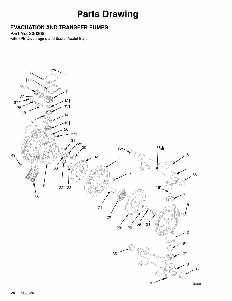
Parts DrawingEVACUATION AND TRANSFER PUMPSPart No. 236265with TPE Diaphragms and Seats, Acetal Balls

308326 25
Parts ListEVACUATION AND TRANSFER PUMPSPart No. 236265with TPE Diaphragms and Seats, Acetal Balls
Ref PartNo. No. Description Qty
Ref PartNo. No. Description Qty
1 188842 MANIFOLD, outlet; aluminum 12 188840 COVER, fluid; aluminum 23 188841 MANIFOLD, inlet; aluminum 14 188839 COVER, air; aluminum 25 188838 HOUSING, center; aluminum 16 115643 SCREW, machine, hex washer hd;
M8 x 1.25; 25 mm (1 in.) long 367 188854 COVER, air valve; aluminum 18 116344 SCREW, machine, hex
flange hd; M5 x 0.8 thread forming; 12 mm (0.47 in.) long 9
9� 188614 BLOCK, pilot; acetal 110� 188618 GASKET, cover; molded Santoprene 111 188855 CARRIAGE, air valve; aluminum 112� 108730 O-RING; nitrile 113� 188616 BLOCK, air valve; acetal 114 188615 PLATE, air valve; stainless steel 115� 188617 SEAL, valve plate; buna-N 116* 112254 BALL, Acetal 417* 188711 SEAT, ball, TPE 420 188607 PLATE, diaphragm; aluminum 421 189044 BOLT, hex hd; M12 x 1.75;
35 mm (1.38 in.) long 2
22*� 112181 PACKING, u-cup; nitrile 423 188609 BEARING, shaft; acetal 224 188608 SHAFT, diaphragm; stainless steel 125* 104319 O-RING; PTFE 226 188610 PIN, push; stainless steel 227� 157628 O-RING; buna-N 228 188611 BEARING, pin; acetal 229* 188606 DIAPHRAGM, TPE 230 188612 PISTON, actuator; acetal 231 188613 BEARING, piston; acetal 232 188603 GASKET, air cover; HDPE foam 235 121497 PLUG, pipe; 1” npt; carbon steel 436 112182 MUFFLER 138� 188970 LABEL, warning 243 116343 SCREW, grounding 1
* These parts are included in the Fluid Section Repair Kits.Refer to page 28 for the correct kit for your pump.
� These parts are included in Air Valve Repair Kit 236273.
� Replacement Danger and Warning labels, tags and cardsare available at no cost.
1
2
3
4
5
6
6
6
6
7 8
8
�9
�10
11
12�13�
14
15�
16*
16*
17*
20
20
21
22�
23
24
25*
2627�
28
29*
30
31
32
35
36
38�
43
�2726
�22
30
17*
22*
35
35
4547
46
03532D
26 308326
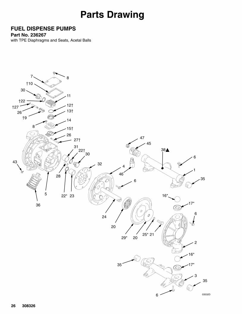
Parts DrawingFUEL DISPENSE PUMPSPart No. 236267with TPE Diaphragms and Seats, Acetal Balls

308326 27
Parts ListFUEL DISPENSE PUMPSPart No. 236267with TPE Diaphragms and Seats, Acetal Balls
Ref PartNo. No. Description Qty
Ref PartNo. No. Description Qty
1 188842 MANIFOLD, outlet; aluminum 12 188840 COVER, fluid; aluminum 23 188841 MANIFOLD, inlet; aluminum 14 188839 COVER, air; aluminum 25 188838 HOUSING, center; aluminum 16 115643 SCREW, machine, hex washer hd;
M8 x 1.25; 25 mm (1 in.) long 367 188854 COVER, air valve; aluminum 18 116344 SCREW, machine, hex flange hd;
M5 x 0.8 thread forming; 12 mm (0.47 in.) long 9
9� 188614 BLOCK, pilot; acetal 110� 188618 GASKET, cover; molded Santoprene 111 188855 CARRIAGE, air valve; aluminum 112� 108730 O-RING; nitrile 113� 188616 BLOCK, air valve; acetal 114 188615 PLATE, air valve; stainless steel 115� 188617 SEAL, valve plate; buna-N 116* 112254 BALL, Acetal 417* 188711 SEAT, ball, TPE 420 188607 PLATE, diaphragm; aluminum 421 189044 BOLT, hex hd; M12 x 1.75;
35 mm (1.38 in.) long 222*� 112181 PACKING, u-cup; nitrile 423 188609 BEARING, shaft; acetal 2
24 188608 SHAFT, diaphragm; stainless steel 125* 104319 O-RING; PTFE 226 188610 PIN, push; stainless steel 227� 157628 O-RING; buna-N 228 188611 BEARING, pin; acetal 229* 188606 DIAPHRAGM, TPE 230 188612 PISTON, actuator; acetal 231 188613 BEARING, piston; acetal 232 188603 GASKET, air cover; HDPE foam 235 121497 PLUG, pipe; 1” npt; carbon steel 336 112182 MUFFLER 138� 188970 LABEL, warning 243 116343 SCREW, grounding 145 166444 ELBOW, reducing, 90�; 1” npt(m) x
two 3/8 npt(f); brass 146 112353 VALVE, relief; 3/8 npt (m x f);
brass with fluoroelastomer seal 147 101754 PLUG, pipe; socket hd; 3/8 npt 1
* These parts are included in the Fluid Section Repair Kits.Refer to page 28 for the correct kit for your pump.
� These parts are included in Air Valve Repair Kit 236273.
� Replacement Danger and Warning labels, tags and cardsare available at no cost.

28 308326
Repair KitsUse Only Genuine Graco Parts and Accessories
Fluid Section Repair Kit D07525For Model 236265 and 236267 Husky 1040 pumps.TPE diaphragms and seats, acetal balls.Includes:
Ref PartNo. No. Description Qty
16 112254 BALL; acetal 417 188711 SEAT, ball; TPE 422 112181 PACKING, u-cup; nitrile 225 104319 O-RING; PTFE 229 188606 DIAPHRAGM; TPE 2
Air Valve Repair Kit 236273For all Husky 1040 pumps. Includes:
Ref PartNo. No. Description Qty
9 188614 BLOCK, pilot; acetal 110 188618 GASKET, cover; molded Santoprene 112 108730 O-RING; nitrile 113 188616 BLOCK, air valve; acetal 115 188617 SEAL, valve plate; buna-N 122 112181 PACKING, u-cup; nitrile 227 157628 O-RING; buna-N 2
Pressure Relief Kit 238428For aluminum Husky 1040 pumps.150 to 180 psi (1.03 to 1.4 MPa, 10.3 to 14 bar)

308326 29
Torque SequenceWhen instructed to torque fasteners, always follow torque sequence.
1. Left/Right Fluid Covers
Torque bolts to 120–150 in–lb (14–17 N�m)
SIDE VIEW
4 2
7
5
3
6
8
1
2. Inlet Manifold
Torque bolts to 120–150 in–lb (14–17 N�m)
BOTTOM VIEW
9 12
11 10
3. Outlet Manifold
Torque bolts to 120–150 in–lb (14–17 N�m)
TOP VIEW
13 16
15 14

30 308326
Dimensions
03536
FRONT VIEW SIDE VIEW
12.28 in.(311.9 mm)
12.0 in.(304.8 mm)
1/2 npt(f)Air Inlet
1” npt(f)Fluid Inlet
1” npt(f)Fluid Outlet
3/4 npt(f)Air Exhaust
(mufflerincluded)
14.0 in.(355.6 mm)
1” npt(f)Optional
Fluid Inlet
5.5 in.(139.7 mm)
1” npt(f)Optional
Fluid Outlet
5 in.(127 mm)
9.25 in.(235 mm)
02682
5 in.(127 mm)
5.5 in.(139.7 mm)
PUMP MOUNTING HOLE PATTERN
Four 0.344 in. (8.7 mm) diameter holes
Model 236267 Shown Model 236267 Shown
03537B
3/8 npt(f)Relief Valve
(236267 only)
308326 31
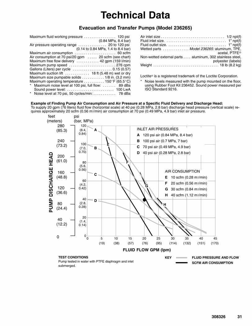
Technical DataEvacuation and Transfer Pumps (Model 236265)
Maximum fluid working pressure 120 psi . . . . . . . . . . . . . . . . . (0.84 MPa, 8.4 bar)
Air pressure operating range 20 to 120 psi . . . . . . . . . . . . . . . (0.14 to 0.84 MPa, 1.4 to 8.4 bar)
Maximum air consumption 60 scfm. . . . . . . . . . . . . . . . . . . . . . Air consumption at 70 psi/20 gpm 20 scfm (see chart). . . . . Maximum free flow delivery 42 gpm (159 l/min). . . . . . . . . . . . Maximum pump speed 276 cpm. . . . . . . . . . . . . . . . . . . . . . . . . Gallons (Liters) per cycle 0.15 (0.57). . . . . . . . . . . . . . . . . . . . . Maximum suction lift 18 ft (5.48 m) wet or dry. . . . . . . . . . . . . Maximum size pumpable solids 1/8 in. (3.2 mm). . . . . . . . . . . . Maximum operating temperature 150�F (65.5�C). . . . . . . . . . . * Maximum noise level at 100 psi, full flow: 89 dBa. . . . . . .
Sound power level: 100 LwA. . . . . . . . . . . . . . . . . . . . . . . . . * Noise level at 70 psi, 50 cycles/min: 78 dBa. . . . . . . . . . . .
Air inlet size 1/2 npt(f). . . . . . . . . . . . . . . . . . . . . . . . . . . . . . . . . . Fluid inlet size. 1” npt(f). . . . . . . . . . . . . . . . . . . . . . . . . . . . . . . . Fluid outlet size. 1” npt(f). . . . . . . . . . . . . . . . . . . . . . . . . . . . . . . Wetted parts Model 236265: aluminum, TPE,. . . . . . . . . . . . . .
acetal, PTFE�Non-wetted external parts aluminum, 302 stainless steel,. . . .
polyester (labels)Weight 18 lb (8.2 kg). . . . . . . . . . . . . . . . . . . . . . . . . . . . . . . . . . .
Loctite� is a registered trademark of the Loctite Corporation.* Noise levels measured with the pump mounted on the floor,
using Rubber Foot Kit 236452. Sound power measured perISO Standard 9216.
0
20
40
60
80
100
120
0 5 10 15 20 25 30 35 40 45
TEST CONDITIONSPump tested in water with PTFE diaphragm and inletsubmerged.
(38) (76) (114) (170)
(2.8,0.28)
(1.4,0.14)
(4.2,0.42)
KEY FLUID PRESSURE AND FLOW
SCFM AIR CONSUMPTION
Example of Finding Pump Air Consumption and Air Pressure at a Specific Fluid Delivery and Discharge Head:To supply 20 gpm (76 liters) fluid flow (horizontal scale) at 40 psi (0.28 MPa, 2.8 bar) discharge head pressure (vertical scale) re-quires approximately 20 scfm (0.56 m/min) air consumption at 70 psi (0.49 MPa, 4.9 bar) inlet air pressure.
FLUID FLOW GPM (lpm)
psi(bar, MPa)
feet(meters)
280(85.3)
240(73.2)
200(61.0)
160(48.8)
120(36.6)
80(24.4)
40(12.2)
0
(5.6,0.56)
(7.0,0.70)
(8.4,0.84)
(19) (57) (95) (132) (151)
INLET AIR PRESSURES
A 120 psi air (0.84 MPa, 8.4 bar)
B 100 psi air (0.7 MPa, 7 bar)
C 70 psi air (0.49 MPa, 4.9 bar)
D 40 psi air (0.28 MPa, 2.8 bar)
A
B
C
D
E
F
G
H
AIR CONSUMPTION
E 10 scfm (0.28 m/min)
F 20 scfm (0.56 m/min)
G 30 scfm (0.84 m/min)
H 40 scfm (1.12 m/min)

32 308326
Technical DataFuel Dispense Pumps (Model 236267)
Maximum fluid working pressure 50 psi (350 kPa, 3.5 bar). . . Air pressure operating range 20 to 50 psi (140 to 350 kPa, . .
1.4 to 3.5 bar)Maximum air consumption 60 scfm. . . . . . . . . . . . . . . . . . . . . . Air consumption at 70 psi/20 gpm 20 scfm (see chart). . . . . Maximum free flow delivery 42 gpm (159 l/min). . . . . . . . . . . . Maximum pump speed 276 cpm. . . . . . . . . . . . . . . . . . . . . . . . . Gallons (Liters) per cycle 0.15 (0.57). . . . . . . . . . . . . . . . . . . . . Maximum suction lift 18 ft (5.48 m) wet or dry. . . . . . . . . . . . . Maximum size pumpable solids 1/8 in. (3.2 mm). . . . . . . . . . . . Maximum operating temperature 150�F (65.5�C). . . . . . . . . . . * Noise level at 50 psi, 50 cycles/min: 78 dBa. . . . . . . . . . . .
Air inlet size 1/2 npt(f). . . . . . . . . . . . . . . . . . . . . . . . . . . . . . . . . . Fluid inlet size. 1” npt(f). . . . . . . . . . . . . . . . . . . . . . . . . . . . . . . . Fluid outlet size. 1” npt(f). . . . . . . . . . . . . . . . . . . . . . . . . . . . . . . Wetted parts Model 236267: aluminum, TPE,. . . . . . . . . . . . . .
fluoroelastomer, acetal, PTFENon-wetted external parts aluminum, 302 stainless steel,. . . .
polyester (labels)Weight 18 lb (8.2 kg). . . . . . . . . . . . . . . . . . . . . . . . . . . . . . . . . . .
Loctite� is a registered trademark of the Loctite Corporation.
* Noise levels measured with the pump mounted on the floor,using Rubber Foot Kit 236452. Sound power measured perISO Standard 9216.
0
10
20
30
40
50
0 5 10 15 20 25 30 35 40 45
TEST CONDITIONSPump tested in water with PTFE diaphragm and inletsubmerged.
(38) (76) (114) (170)
(2.1,210)
(1.4,140)
KEY FLUID PRESSURE AND FLOW
SCFM AIR CONSUMPTION
Example of Finding Pump Air Consumption and Air Pressure at a Specific Fluid Delivery and Discharge Head:To supply 20 gpm (76 liters) fluid flow (horizontal scale) at 20 psi (140 kPa, 1.4 bar) discharge head pressure (vertical scale) requiresapproximately 11 scfm (0.31 m/min) air consumption at 40 psi (280 kPa, 2.8 bar) inlet air pressure.
FLUID FLOW GPM (lpm)
psi(bar,kPa)
feet(meters)
80(24.4)
40(12.2)
0
(19) (57) (95) (132) (151)
INLET AIR PRESSURE
D 40 psi air (280 kPa, 2.8 bar)
D
E F
AIR CONSUMPTION
E 10 scfm (0.28 m/min)
F 20 scfm (0.56 m/min)
(3.5,350)
(2.8,280)
(0.7,70)
308326 33
Notes

34 308326
Graco WarrantiesGraco Standard Husky Pump WarrantyGraco warrants all equipment manufactured by Graco and bearing its name to be free from defects in material and workmanship on thedate of sale to the original purchaser for use. With the exception of any special, extended, or limited warranty published by Graco,Graco will, for a period of five years from the date of sale, repair or replace any part of the equipment determined by Graco to bedefective. This warranty applies only when the equipment is installed, operated and maintained in accordance with Graco’s writtenrecommendations.
This warranty does not cover, and Graco shall not be liable for general wear and tear, or any malfunction, damage or wear caused byfaulty installation, misapplication, abrasion, corrosion, inadequate or improper maintenance, negligence, accident, tampering, orsubstitution of non-Graco component parts. Nor shall Graco be liable for malfunction, damage or wear caused by the incompatibility ofGraco equipment with structures, accessories, equipment or materials not supplied by Graco, or the improper design, manufacture,installation, operation or maintenance of structures, accessories, equipment or materials not supplied by Graco.
This warranty is conditioned upon the prepaid return of the equipment claimed to be defective to an authorized Graco distributor forverification of the claimed defect. If the claimed defect is verified, Graco will repair or replace free of charge any defective parts. Theequipment will be returned to the original purchaser transportation prepaid. If inspection of the equipment does not disclose any defectin material or workmanship, repairs will be made at a reasonable charge, which charges may include the costs of parts, labor, andtransportation.
THIS WARRANTY IS EXCLUSIVE, AND IS IN LIEU OF ANY OTHER WARRANTIES, EXPRESS OR IMPLIED, INCLUDING BUTNOT LIMITED TO WARRANTY OF MERCHANTABILITY OR WARRANTY OF FITNESS FOR A PARTICULAR PURPOSE.
Graco’s sole obligation and buyer’s sole remedy for any breach of warranty shall be as set forth above. The buyer agrees that no otherremedy (including, but not limited to, incidental or consequential damages for lost profits, lost sales, injury to person or property, or anyother incidental or consequential loss) shall be available. Any action for breach of warranty must be brought within six years of the dateof sale.
Graco makes no warranty, and disclaims all implied warranties of merchantability and fitness for a particular purpose in connectionwith accessories, equipment, materials or components sold but not manufactured by Graco. These items sold, but not manufacturedby Graco (such as electric motors, switches, hose, etc.), are subject to the warranty, if any, of their manufacturer. Graco will providepurchaser with reasonable assistance in making any claim for breach of these warranties.
In no event will Graco be liable for indirect, incidental, special or consequential damages resulting from Graco supplying equipmenthereunder, or the furnishing, performance, or use of any products or other goods sold hereto, whether due to a breach of contract,breach of warranty, the negligence of Graco, or otherwise.
FOR GRACO CANADA CUSTOMERSThe parties acknowledge that they have required that the present document, as well as all documents, notices and legal proceedingsentered into, given or instituted pursuant hereto or relating directly or indirectly hereto, be drawn up in English. Les partiesreconnaissent avoir convenu que la rédaction du présente document sera en Anglais, ainsi que tous documents, avis et procéduresjudiciaires exécutés, donnés ou intentés à la suite de ou en rapport, directement ou indirectement, avec les procedures concernées.
Extended Product WarrantyGraco warrants all Husky 205, 307, 515, 716, 1040, 1590, 2150, and 3275 air valve center sections to be free from defects in materialand workmanship for a period of fifteen years from date installed in service by the original purchaser. Normal wear of items such aspackings or seals are not considered to be defects in material and workmanship.
Five years Graco will provide parts and labor.Six to Fifteen years Graco will replace defective parts only.
Graco InformationTO PLACE AN ORDER, contact your Graco distributor, or call one of the following numbers
to identify the distributor closest to you:1–800–328–0211 Toll Free
612–623–6921 612–378–3505 Fax
All written and visual data contained in this document reflects the latest product information available at the time of publication.Graco reserves the right to make changes at any time without notice.
This manual contains English. MM 308326
Graco Headquarters: MinneapolisInternational Offices: Belgium, China, Japan, Korea
www.graco.com308326 05/1994, Revised 7/2008