3 - sites.levittownschools.comsites.levittownschools.com/.../ch09_ppa7_instructorman… · web...
TRANSCRIPT

STATIC EQUILIBRIUM; ELASTICITY AND FRACTURE
9Responses to Questions
1. If the object has a net force on it of zero, then its center of mass does not accelerate. But since it is not in equilibrium, it must have a net torque and therefore an angular acceleration. Some examples are:
• A compact disk in a player as it comes up to speed, after it has just been inserted.• A hard drive on a computer when the computer is first turned on.• A window fan immediately after the power to it has been shut off.• The drum of a washing machine while it is speeding up or slowing down.
2. The bungee jumper is not in equilibrium, because the net force on the jumper is not zero. If the jumper were at rest and the net force were zero, then the jumper would stay at rest by Newton’s first law. The jumper has a net upward force when at the bottom of the dive, and that is why the jumper is then pulled back upward.
3. The meter stick is originally supported by both fingers. As you start to slide your fingers together, more of the weight of the meter stick is supported by the finger that is closest to the center of gravity, so the torques produced by the fingers are equal and the stick is in equilibrium. The other finger feels a smaller normal force, and therefore a smaller frictional force, so the stick slides more easily and moves closer to the center of gravity. The roles switch back and forth between the fingers as they alternately move closer to the center of gravity. Your fingers will eventually meet at the center of gravity.
4. Like almost any beam balance, the movable weights are connected to the fulcrum point by relatively long lever arms, while the platform on which you stand is connected to the fulcrum point by a very short lever arm. The scale “balances” when the torque provided by your weight (large mass, small lever arm) is equal to that provided by the sliding weights (small mass, large lever arm).
5. (a) If we assume that the pivot point of rotation is the lower left corner of the wall in the picture, then the gravity force acting through the CM provides the torque to keep the wall upright. Note that the gravity force would have a relatively small lever arm (about half the width of the wall). Thus, the sideways force would not have to be particularly large to start to move the wall.
(b) With the horizontal extension, there are factors that make the wall less likely to overturn:• The mass of the second wall is larger, so the torque caused by gravity (helping to keep
the wall upright) will be larger for the second wall.• The center of gravity of the second wall is farther to the right of the pivot point, so
gravity exerts a larger torque to counteract the torque due to • The weight of the ground above the new part of the wall provides a large clockwise
torque that helps counteract the torque due to
6. If the sum of the forces on an object is not zero, then the CM of the object will accelerate in the direction of the net force. If the sum of the torques on the object is zero, then the object has no angular acceleration. Some examples are:
• A satellite in a circular orbit around the Earth.
© Copyright 2014 Pearson Education, Inc. All rights reserved. This material is protected under all copyright laws as they currently exist. No portion of this material may be reproduced, in any form or by any means, without permission in writing from the publisher.
9-1

9-2 Chapter 9
• A block sliding down an inclined plane.• An object that is in projectile motion but not rotating.• The startup motion of an elevator, changing from rest to having a nonzero velocity.
7. When the person stands near the top, the ladder is more likely to slip. In the accompanying diagram, the force of the person pushing down on the ladder causes a clockwise torque about the contact point with the ground, with lever arm The only force causing a counterclockwise torque about that same point is the reaction force of the wall on the ladder, While the ladder is in
equilibrium, will be the same magnitude as the frictional force
at the ground, Since has a maximum value, will
have the same maximum value, and will have a maximum counterclockwise torque that it can exert. As the person climbs the ladder, his lever arm gets longer, so the torque due to his weight gets larger. Eventually, if the torque caused by the person is larger than the maximum torque caused by
the ladder will start to slip—it will not stay in equilibrium.
8. The mass of the meter stick is equal to the mass of the rock. Since the meter stick is uniform, its center of mass is at the 50-cm mark. In terms of rotational motion about a pivot at the 25-cm mark, we can treat the stick as though its entire mass is concentrated at the center of mass. The meter stick’s mass at the 50-cm mark (25 cm from the pivot) balances the rock at the 0 mark (also 25 cm from the pivot), so the masses must be equal.
9. You lean backward in order to keep your center of mass over your feet. If, due to the heavy load, your center of mass is in front of your feet, you will fall forward.
10. (a) The cone will be in stable equilibrium if it is placed flat on its base. If it is tilted slightly from this position and then released, it will return to the original position.
(b) The cone will be in unstable equilibrium if it is balanced on its tip. A slight displacement in this case will cause the cone to topple over.
(c) If the cone is placed on its side, it will be in neutral equilibrium. If the cone is displaced slightly while on its side, it will remain in its new position.
11. When you rise on your tiptoes, your CM shifts forward. Since you are already standing with your nose and abdomen against the door, your CM cannot shift forward. Thus gravity exerts a torque on you and you are unable to stay on your tiptoes—you will return to being flat-footed on the floor.
© Copyright 2014 Pearson Education, Inc. All rights reserved. This material is protected under all copyright laws as they currently exist. No portion of this material may be reproduced, in any form or by any means, without permission in writing from the publisher.
stable unstable neutralequilib. equilib. equilib.
dy
xy
Ly
dx
mg
Mg
WF
G xF
G yF

Static Equilibrium; Elasticity and Fracture 9-3
12. When you start to stand up from a normal sitting position, your CM is not over your point of support (your feet), so gravity will exert a torque about your feet that rotates you back down into the chair. You must lean forward in order that your CM is over your feet so that you can stand up.
13. While you are doing a sit-up, your abdomen muscles provide a torque to rotate you up away from the floor. The force of gravity on your upper half-body tends to pull you back down to the floor, which makes doing sit-ups difficult. The force of gravity on your lower half-body provides a torque that opposes the torque caused by the force of gravity on your upper half-body, making the sit-up a little easier. When your legs are bent, the lever arm for the lower half-body is shorter, so less counter-torque is available.
14. For rotating the upper half-body, the pivot point is near the waist and hips. In that position, the arms have a relatively small torque, even when extended, due to their smaller mass. The more massive trunk–head combination has a very short lever arm, so it also has a relatively small torque. Thus, the force of gravity on the upper body causes relatively little torque about the hips, tending to rotate you forward, and the back muscles need to produce little torque to keep you from rotating forward. The force on the upper half-body due to the back muscles is small, so the (partially rightward) force at the base of the spinal column (not shown in the diagram), to keep the spine in equilibrium, will be small.
When you stand and bend over, the lever arm for the upper body is much larger than while you are sitting, which causes a much larger torque. The CM of the arms is also farther from the support point and causes more torque. The back muscles, assumed to act at the center of the back, do not have a very long lever arm. Thus the back muscles will have to exert a large force to cause a counter-torque that keeps you from falling over. Accordingly, there will have to be a large force (mostly to the right, and not drawn in the diagram) at the base of the spine to keep the spine in equilibrium.
15. Configuration (b) is more likely to be stable. In configuration (a), the CG of the bottom brick is at the edge of the table, and the CG of the top brick is to the right of the edge of the table. Thus the CG of the two-brick system is not above the base of support, and gravity will exert a torque to roll the bricks clockwise off the table. Another way to see this is that more than 50% of the brick mass is not above the base of support—50% of the bottom brick and 75% of the top brick are to the right of the edge of the table. It is not in equilibrium.
In configuration (b), exactly half of the mass (75% of the top brick and 25% of the bottom brick) is over the edge of the table. Thus the CG of the pair is at the edge of the table—it is in unstable equilibrium.
16. A is a point of unstable equilibrium, B is a point of stable equilibrium, and C is a point of neutral equilibrium.
17. The Young’s modulus for a bungee cord is much smaller than that for ordinary rope. We know that a
bungee cord stretches more easily than ordinary rope. From Eq. 9–4, we have The value
of Young’s modulus is inversely proportional to the change in length of a material under a tension. Since the change in length of a bungee cord is much larger than that of an ordinary rope if other conditions are identical (stressing force, unstretched length, cross-sectional area of rope or cord), it must have a smaller Young’s modulus.
18. An object under shear stress has equal and opposite forces applied across its opposite faces. This is exactly what happens with a pair of scissors. One blade of the scissors pushes down on the cardboard,
© Copyright 2014 Pearson Education, Inc. All rights reserved. This material is protected under all copyright laws as they currently exist. No portion of this material may be reproduced, in any form or by any means, without permission in writing from the publisher.

9-4 Chapter 9
while the other blade pushes up with an equal and opposite force, at a slight displacement. This produces a shear stress in the cardboard, which causes it to fail.
19. Concrete or stone should definitely not be used for the support on the left. The left-hand support pulls downward on the beam, so the beam must pull upward on the support. Therefore, the support will be under tension and should not be made of ordinary concrete or stone, since these materials are weak under tension. The right-hand support pushes up on the beam, so the beam pushes down on it; it will therefore be under a compression force. Making this support of concrete or stone would be acceptable.
Responses to MisConceptual Questions
1. (d) In attempting to solve this problem, students frequently try to divide the beam into multiple parts to calculate the torque due to the weight of the beam. The beam should be considered as a single object with its weight acting at its center of mass from the pivot). Since the woman is on the opposite side of the pivot and at the same distance as the beam’s center of mass, their forces of gravity and masses must be equal.
2. (d) A common misconception is that a nonrotating object has an axis of rotation. If an object is not rotating, it is not rotating about any arbitrary point. When solving an equilibrium problem with no rotation, the student can select any axis for the torques that facilitates solving the problem.
3. (a) Students might think that for the net force on the beam to be zero, the tension would equal the weight of the beam. However, this does not take into account the force that the wall exerts on the hinged end. Students might assume that the tension is equal to half of the beam’s weight. However, this does not take into account the vector nature of the tension. The vertical component of the tension is equal to half of the weight, but there is also a horizontal component. Adding these two components yields a tension at least half of the weight of the beam.
4. (c) Drawing a free-body diagram for this problem will resolve student misconceptions. When the ball is pulled to the side, there are three forces acting on the ball: the vertical weight, the horizontal applied force, and the tension along the direction of the cable. Resolving the tension into horizontal and vertical parts and applying Newton’s second law in equilibrium, we can see that the applied force is equal to the horizontal component of the tension.
5. (a) As the child leans forward, her center of mass moves closer to the pivot point, which decreases her lever arm. The seesaw is no longer in equilibrium. Since the torque on her side has decreased, she will rise.
6. (c) A common misconception is that each cord will support one-half of the weight regardless of the angle. An analysis of the forces using Newton’s second law in equilibrium shows that the horizontal components of the tension are equal. Since cord A makes a larger angle with the horizontal, it has a greater total tension and therefore supports more than half the suspended weight.
7. (c) The applied force is proportional to the stress, so increasing the force will affect the stress. The strain is how the rope responds to the stress. Increasing the force will then affect the strain. Young’s modulus is the constant of proportionality between the stress and strain. It is determined by the properties of the material, so it is not affected by pulling on the rope.
8. (e) Students may consider the tension equal to the woman’s weight, or half of the woman’s weight, if they do not consider the vector nature of the forces. A free-body diagram for the point at the
© Copyright 2014 Pearson Education, Inc. All rights reserved. This material is protected under all copyright laws as they currently exist. No portion of this material may be reproduced, in any form or by any means, without permission in writing from the publisher.

Static Equilibrium; Elasticity and Fracture 9-5
bottom of the woman’s foot shows three forces acting: the weight of the woman and the diagonal tensions in the wire on each side of her foot. Applying Newton’s second law in equilibrium in the vertical direction shows that the vertical component of the tension must equal half of her weight. Since vertical displacement is small compared to the horizontal length of the wire, the total tension is much greater than the vertical component of the tension.
9. (d) When the length, width, and number of floors are doubled, the weight of the garage increases by a factor of eight. To keep the stress on the columns unchanged, the area of the columns should also increase by a factor of eight.
10. (d) The stress (applied force) is proportional to the strain (change in length). Doubling the stress will cause the strain to double also.
Solutions to Problems
1. If the tree is not accelerating, then the net force in all directions is 0.
So is 528 N, at an angle of clockwise from The angle has 3 significant figures.
2. Because the mass m is stationary, the tension in the rope pulling up on the sling must be mg, and the force of the sling on the leg must be mg, upward. Calculate torques about the hip joint, with counterclockwise torque taken as positive. See the free-body diagram for the leg. Note that the forces on the leg exerted by the hip joint are not drawn, because they do not exert a torque about the hip joint.
3. (a) See the free-body diagram. Calculate torques about the pivot point P labeled in the diagram. The upward force at the pivot will not have any torque. The total torque is zero, since the crane is in equilibrium.
(b) Again, we sum torques about the pivot point. Mass m is the unknown in this case, and the counterweight is at its maximum distance from the pivot.
© Copyright 2014 Pearson Education, Inc. All rights reserved. This material is protected under all copyright laws as they currently exist. No portion of this material may be reproduced, in any form or by any means, without permission in writing from the publisher.
BF
CF
AF
105
x1
x2mg
M g
PF
m g
x
M g
d
P

9-6 Chapter 9
4. Her torque is her weight times the distance x between the diver and the left support post.
5. (a) Let m = 0. Calculate the net torque about the left end of the diving board, with counterclockwise torques positive. Since the board is in equilibrium, the net torque is zero.
Use Newton’s second law in the vertical direction to find
(b) Repeat the basic process, but with m = 28 kg. The weight of the board will add more clockwise torque.
6. Since each half of the forceps is in equilibrium, the net torque on each half of the forceps is zero. Calculate torques with respect to an axis perpendicular to the plane of the forceps, through point P, counterclockwise being positive. Consider a force diagram for one-half of the forceps. is the force on the half-forceps due to the plastic rod, and force is the force on the half-forceps from the pin joint.
exerts no torque about point P.
The force that the forceps exerts on the rod is the opposite of so it is also
7. Write Newton’s second law for the junction, in both the x and y directions.
From this, we see that Thus set
8. Since the backpack is midway between the two trees, the angles in the diagram are equal. Write Newton’s second law for the vertical direction
© Copyright 2014 Pearson Education, Inc. All rights reserved. This material is protected under all copyright laws as they currently exist. No portion of this material may be reproduced, in any form or by any means, without permission in writing from the publisher.
mg
AF
BF
mgTF
TF
y
AF
BF
mg M g1.0 m
2.0 m4.0 m
TF
1F
Td
1d
PF

Static Equilibrium; Elasticity and Fracture 9-7
for the point at which the backpack is attached to the cord, with the weight of the backpack being the downward vertical force. The angle is determined by the distance between the trees and the amount of sag at the midpoint, as illustrated in the second diagram.
(a)
(b)
9. Let m be the mass of the beam, and M be the mass of the piano. Calculate torques about the left end of the beam, with counterclockwise torques positive. The conditions of equilibrium for the beam are used to find the forces that the support exerts on the beam.
The forces on the supports are equal in magnitude and opposite in direction to the above two results.
10. Calculate torques about the left end of the beam, with counterclockwise torques positive. The conditions of equilibrium for the beam are used to find the forces that the support exerts on the beam.
Notice that points down.
© Copyright 2014 Pearson Education, Inc. All rights reserved. This material is protected under all copyright laws as they currently exist. No portion of this material may be reproduced, in any form or by any means, without permission in writing from the publisher.
l/4l
mgM gLF
RF
AF
BF
mg20.0 m
25.0 m

9-8 Chapter 9
11. The pivot should be placed so that the net torque on the board is zero. We calculate torques about the pivot point, with counterclockwise torques positive. The upward force at the pivot point is shown, but it exerts no torque about the pivot point. The mass of the child is m, the mass of the adult is M, the mass of the board is and the center of gravity is at the middle of the board.
(a) Ignore the force
(b) Include the force
12. Using the free-body diagram, write Newton’s second law for both the horizontal and vertical directions, with net forces of zero.
13. Draw a free-body diagram of the junction of the three wires. The tensions can be found from the conditions for force equilibrium.
© Copyright 2014 Pearson Education, Inc. All rights reserved. This material is protected under all copyright laws as they currently exist. No portion of this material may be reproduced, in any form or by any means, without permission in writing from the publisher.
l/2 – x
mgBm gMg
PF
x x
mgT2F
T1F
T1F
T2F
mg
3753

Static Equilibrium; Elasticity and Fracture 9-9
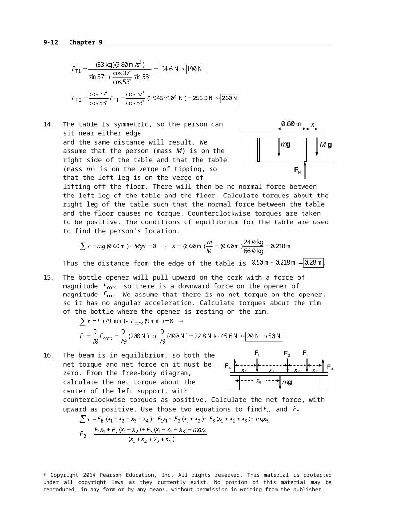
14. The table is symmetric, so the person can sit near either edge and the same distance will result. We assume that the person (mass M) is on the right side of the table and that the table (mass m) is on the verge of tipping, so that the left leg is on the verge of lifting off the floor. There will then be no normal force between the left leg of the table and the floor. Calculate torques about the right leg of the table such that the normal force between the table and the floor causes no torque. Counterclockwise torques are taken to be positive. The conditions of equilibrium for the table are used to find the person’s location.
Thus the distance from the edge of the table is
15. The bottle opener will pull upward on the cork with a force of magnitude so there is a downward force on the opener of magnitude We assume that there is no net torque on the opener, so it has no angular acceleration. Calculate torques about the rim of the bottle where the opener is resting on the rim.
16. The beam is in equilibrium, so both the net torque and net force on it must be zero. From the free-body diagram, calculate the net torque about the center of the left support, with counterclockwise torques as positive. Calculate the net force, with upward as positive. Use those two equations to find and
17. From the free-body diagram, the conditions of equilibrium are used to find the location of the girl (mass ). The 45-kg boy is represented by and the 35-kg boy by
Calculate torques about the center of the seesaw, and take counterclockwise torques to be positive. The upward force of the fulcrum on the seesaw causes no torque about the center.
© Copyright 2014 Pearson Education, Inc. All rights reserved. This material is protected under all copyright laws as they currently exist. No portion of this material may be reproduced, in any form or by any means, without permission in writing from the publisher.
mg M g
x0.60 m
NF
x1 x2 x3 x4
mg
AF
BF
1F
2F
3F
5 x
Cm gAm gBm gF
x

9-10 Chapter 9
18. The beam is in equilibrium. Use the conditions of equilibrium to calculate the tension in the wire and the forces at the hinge. Calculate torques about the hinge, and take counterclockwise torques to be positive.
19. (a) The pole is in equilibrium, so the net torque on it must be zero. From the free-body diagram, calculate the net torque about the lower end of the pole, with counterclockwise torques as positive. Use that calculation to find the tension in the cable. The length of the pole is
(b) The net force on the pole is also zero since it is in equilibrium. Write Newton’s second law in both the x and y directions to solve for the forces at the pivot.
20. The center of gravity of each beam is at its geometric center. Calculate torques about the left end of the beam, and take counterclockwise torques to be positive. The conditions of equilibrium for the beam are used to find the forces that the support exerts on the beam.
21. To find the normal force exerted on the road by the trailer tires, take the torques about point B, with counterclockwise torques as positive.
© Copyright 2014 Pearson Education, Inc. All rights reserved. This material is protected under all copyright laws as they currently exist. No portion of this material may be reproduced, in any form or by any means, without permission in writing from the publisher.
1m g
TF
HF
1 2
2
1
2m g
AF
BF1
2 Mg
M g4
2
mg
AF
BF
2.5 m 5.5 m
x
ymg
M gTF
P xF
P yF
h
cos

Static Equilibrium; Elasticity and Fracture 9-11
The net force in the vertical direction must be zero.
22. (a) For the extreme case of the beam being ready to tip, there would be no normal force at point A from the support. Use the free-body diagram to write the equation of rotational equilibrium under that condition to find the weight of the person, with Take torques about the location of support B, and call counterclockwise torques positive. is the weight of the person, and is the mass of the beam.
(b) With the person standing at point D, we have already assumed that The net force in the vertical direction must also be zero.
(c) The person moves to a different spot, so the free-body diagram changes again as shown. Again use the net torque about support B and then use the net vertical force.
23. Draw the free-body diagram for the sheet, and write Newton’s second law for the vertical direction. Note that the tension is the same in both parts of the clothesline.
The 60-N tension is much higher than the ~7.5-N weight of the sheet because of the small angle. Only the vertical components of the tension are supporting the sheet. Since the angle is small, the tension has to be large to have a large enough vertical component to hold up the sheet.
© Copyright 2014 Pearson Education, Inc. All rights reserved. This material is protected under all copyright laws as they currently exist. No portion of this material may be reproduced, in any form or by any means, without permission in writing from the publisher.
TF
TF
mg
3.53.5
3.0 m 7.0 m 5.0 m 5.0 m
AF
BF
W
Bm g
C A B D
3.0 m 5.0 m 5.0 m
2.0 m
AF BF
W
Bm g
C A B D
mg
W
hingehoriz
F
ropeF
hingevert
F
d
xy
9-12 Chapter 9
24. The person is in equilibrium, so both the net torque and net force must be zero. From the free-body diagram, calculate the net torque about the center of gravity, with counterclockwise torques as positive. Use that calculation to find the location of the center of gravity, a distance from the feet.
The center of gravity is about 90.5 cm from the feet.
25. (a) The man is in equilibrium, so the net force and the net torque on him must be zero. We use half of his weight and then consider the force just on one hand and one foot, assuming that he is symmetrical. Take torques about the point where the foot touches the ground, with counterclockwise as positive.
(b) Use Newton’s second law for vertical forces to find the force on the feet.
The value of 100 N has 2 significant figures.
26. First consider the triangle made by the pole and one of the wires (first diagram). It has a vertical leg of 2.6 m and a horizontal leg of 2.0 m. The angle that the tension (along the wire) makes with the vertical is
The part of the tension that is parallel to the ground is
therefore
Now consider a top view of the pole, showing only force parallel to the ground (second diagram). The horizontal parts of the tension lie as the sides of an equilateral triangle, so each makes a 30° angle with the tension force of the net. Write the equilibrium equation for the forces along the direction of the tension in the net.
27. (a) Choose the coordinates as shown in the free-body diagram.(b) Write the equilibrium conditions for the horizontal and vertical forces.
© Copyright 2014 Pearson Education, Inc. All rights reserved. This material is protected under all copyright laws as they currently exist. No portion of this material may be reproduced, in any form or by any means, without permission in writing from the publisher.
2.6 m
2.0 m
o30 o30
netF
T hF
T hF
d1 d2
12 mg
hF
fF
–x x
mgAF
BF

Static Equilibrium; Elasticity and Fracture 9-13
So the vertical hinge force actually points downward.
(c) We take torques about the hinge point, with clockwise torques as positive.
29. The forces on the door are due to gravity and the hinges. Since the door is in equilibrium, the net torque and net force must be zero. Write the three equations of equilibrium. Calculate torques about the bottom hinge, with counterclockwise torques as positive. From the statement of the problem,
30. Write the conditions of equilibrium for the ladder, with torques taken about the bottom of the ladder and counterclockwise torques as positive.
© Copyright 2014 Pearson Education, Inc. All rights reserved. This material is protected under all copyright laws as they currently exist. No portion of this material may be reproduced, in any form or by any means, without permission in writing from the publisher.
x
ymg
WF
G yF
G xF
cos
sin
d
h
w
d
xy
mg
B xF
B yF
A xF
A yF

d
mg MgMF
D
9-14 Chapter 9
For the ladder not to slip, the force at the ground must be less than or equal to the maximum force of static friction.
Thus the minimum angle is
31. The arm is in equilibrium. Take torques about the elbow joint (the dot in the free-body diagram), so that the force at the elbow joint does not enter the calculation. Counterclockwise torques are positive. The mass of the lower arm is and the mass of the load is
It is given that
32. Calculate the torques about the elbow joint (the dot in the free-body diagram). The arm is in equilibrium. Counterclockwise torques are positive.
33. We redraw Figs. 9–14b and 9–14c with the person 45° from the horizontal, instead of the original 30°. All distances are as in the original problem. We still assume that the back muscles pull at a 12° angle to the spine. The 18° angle from the original problem becomes 33°. Torques are taken about the same point at the base of the spine, with counterclockwise torques as positive.
As in the original problem, The torque equation then gives the following result:
Take the sum of the forces in the vertical direction, set equal to zero.
© Copyright 2014 Pearson Education, Inc. All rights reserved. This material is protected under all copyright laws as they currently exist. No portion of this material may be reproduced, in any form or by any means, without permission in writing from the publisher.
mg MgJF
MF
1d
2 d3 d
45o
MF
VF
TwAw
Hw

Static Equilibrium; Elasticity and Fracture 9-15
Take the sum of the forces in the horizontal direction, set equal to zero.
The final result is
This compares with 2.5w for the more bent position.
34. (a) Calculate the torques about the elbow joint (the dot in the free-body diagram). The arm is in equilibrium. Take counterclockwise torques as positive.
(b) To find the components of write Newton’s second law for both the x and y directions. Then combine them to find the magnitude.
35. Calculate the torques about the shoulder joint, which is at the left end of the free-body diagram of the arm. Since the arm is in equilibrium, the sum of the torques will be zero. Take counterclockwise torques to be positive. The force due to the shoulder joint is drawn, but it exerts no torque about the shoulder joint.
36. There will be a normal force upward at the ball of the foot, equal to the person’s weight Calculate torques about a point on the floor directly below the leg bone (and in line with the leg bone force, Since the foot is in equilibrium, the sum of the torques will be zero. Take counterclockwise torques as positive.
The net force in the y direction must be zero. Use that to find
© Copyright 2014 Pearson Education, Inc. All rights reserved. This material is protected under all copyright laws as they currently exist. No portion of this material may be reproduced, in any form or by any means, without permission in writing from the publisher.
mg M g
MF
JF
dD
l
NF
d 2D d
AF
BF
mg
MF
JF
Dd

9-16 Chapter 9
37. Take torques about the elbow joint. Let clockwise torques be positive. Since the arm is in equilibrium, the total torque will be 0.
38. From Section 9–4: “An object whose CG is above its base of support will be stable if a vertical line projected downward from the CG falls within the base of support.” For the tower, the base of support is a circle of radius 7.7 m. If the top is 4.5 m off center, then the CG will be 2.25 m off center, and a vertical line downward from the CG will be 2.25 m from the center of the base. As long as that vertical line is less than 7.7 m from the center of the base, the tower will be in
. To be unstable, the CG has to be more than 7.7 m off center, so the top must be more than 2 × (7.7 m) = 15.4 m off center. Thus the top will have to lean 15.4 m – 4.5 m = farther to reach the verge of instability.
39. (a) The maximum distance for brick #1 to remain on brick #2 will be reached when the CM of brick #1 is directly over the edge of brick #2. Thus brick #1 will overhang brick #2 by
The maximum distance for the top two bricks to remain on brick #3 will be reached when the center of mass of the top two bricks is directly over the edge of brick #3. The CM of the top two bricks is (obviously) at the point labeled X on brick #2, a distance of from the right edge of brick #2. Thus The maximum distance for the top three bricks to remain on brick #4 will be reached when the center of mass of the top three bricks is directly over the edge of brick #4. The CM of the top three bricks is at the point labeled X on brick #3 and is found relative to the center of brick # 3 by
or from the right edge of
brick #3. Thus
The maximum distance for the four bricks to remain on a tabletop will be reached when the center of mass of the four bricks is directly over the edge of the table. The CM of all four bricks is at the point labeled X on brick #4 and is found relative to the center of brick #4 by
or from the right edge
of brick #4. Thus
(b) From the last diagram, the distance from the edge of the tabletop to the right edge of brick #1 is
Since this distance is greater than the answer is yes, the first brick is completely beyond the edge of the table.
© Copyright 2014 Pearson Education, Inc. All rights reserved. This material is protected under all copyright laws as they currently exist. No portion of this material may be reproduced, in any form or by any means, without permission in writing from the publisher.
1x#1
#2
#1
1xx#2#3 2x
1x#1
#2#3 2xx
#4 3x
1x#1
#2#3 2x
#4 3x4x
x
Vertical Ready to fall

Static Equilibrium; Elasticity and Fracture 9-17
(c) From the work in part (a), we see that the general formula for the total distance spanned by n bricks is
(d) The arch is to span 1.0 m, so the span from one side will be 0.50 m. Thus, we must solve
Evaluation of this expression for various values of n shows that 15 bricks
will span a distance of 0.498 m and that 16 bricks will span a distance of 0.507 m. Thus, it takes 16 bricks for each half-span, plus 1 brick on top and 1 brick as the base on each side (as in Fig. 9–67b), for a total of .
40. The amount of stretch can be found using the elastic modulus in Eq. 9–4.
41. (a)
(b)
42. The change in length is found from the strain.
43. (a)
(b)
(c)
44. The change in volume is given by Eq. 9–7. We assume the original pressure is atmospheric pressure,
45. The relationship between pressure change and volume change is given by Eq. 9–7.
© Copyright 2014 Pearson Education, Inc. All rights reserved. This material is protected under all copyright laws as they currently exist. No portion of this material may be reproduced, in any form or by any means, without permission in writing from the publisher.

9-18 Chapter 9
46. The Young’s modulus is the stress divided by the strain.
47. The mass can be calculated from the equation for the relationship between stress and strain. The force causing the strain is the weight of the mass suspended from the wire. Use Eq. 9–4.
48. The percentage change in volume is found by multiplying the relative change in volume by 100. The change in pressure is 199 times atmospheric pressure, since it increases from atmospheric pressure to 200 times atmospheric pressure. Use Eq. 9–7.
The negative sign indicates that the interior space got smaller.
49. Elastic potential energy is given by The force is found from Eq. 9–4, using as
50. Set the compressive strength of the bone equal to the stress of the bone.
51. (a) The maximum tension can be found from the ultimate tensile strength of the material.
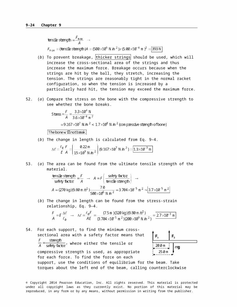
(b) To prevent breakage, thicker strings should be used, which will increase the cross-sectional area of the strings and thus increase the maximum force. Breakage occurs because when the strings are hit by the ball, they stretch, increasing the tension. The strings are reasonably tight in the normal racket configuration, so when the tension is increased by a particularly hard hit, the tension may exceed the maximum force.
52. (a) Compare the stress on the bone with the compressive strength to see whether the bone breaks.
© Copyright 2014 Pearson Education, Inc. All rights reserved. This material is protected under all copyright laws as they currently exist. No portion of this material may be reproduced, in any form or by any means, without permission in writing from the publisher.

Static Equilibrium; Elasticity and Fracture 9-19
(b) The change in length is calculated from Eq. 9–4.
53. (a) The area can be found from the ultimate tensile strength of the material.
(b) The change in length can be found from the stress-strain relationship, Eq. 9–4.
54. For each support, to find the minimum cross-sectional area with a
safety factor means that where either the tensile or
compressive strength is used, as appropriate for each force. To find the force on each support, use the conditions of equilibrium for the beam. Take torques about the left end of the beam, calling counterclockwise torques positive, and also sum the vertical forces, taking upward forces as positive.
Notice that the forces on the supports are the opposite of and So the force on support A is directed upward, which means that support A is in tension. The force on support B is directed downward, so support B is in compression.
55. The maximum shear stress is to be 1/7th of the shear strength for iron. The maximum stress will occur for the minimum area and thus the minimum diameter.
© Copyright 2014 Pearson Education, Inc. All rights reserved. This material is protected under all copyright laws as they currently exist. No portion of this material may be reproduced, in any form or by any means, without permission in writing from the publisher.
AF
BF
mg20.0 m
25.0 m

9-20 Chapter 9
56. From the free-body diagram, write Newton’s second law for the vertical direction. Solve for the maximum tension required in the cable, which will occur for an upward acceleration.
The maximum stress is to be 1/8th of the tensile strength for steel. The maximum stress will occur for the minimum area and thus the minimum diameter.
57. Draw free-body diagrams similar to Figs. 9–31a and 9–31b for the forces on the right half of a round arch and a pointed arch. The load force is placed at the same horizontal position on each arch. For each half-arch, take torques about the lower right-hand corner, with counterclockwise as positive.
For the round arch:
For the pointed arch:
Solve for given that
58. Write Newton’s second law for the horizontal direction.
Thus the two forces are the same size. Now write Newton’s second law for the vertical direction.
59. (a) The pole will exert a downward force and a clockwise torque about the woman’s right hand. Thus there must be an upward force exerted by the left hand to cause a counterclockwise torque
© Copyright 2014 Pearson Education, Inc. All rights reserved. This material is protected under all copyright laws as they currently exist. No portion of this material may be reproduced, in any form or by any means, without permission in writing from the publisher.
mg
TF
2F
1F
ButtressF
Hround
F
Hround
F
VF
LoadF
R
R
x
Hpointed
F
HF
VF
LoadF
R
y
x
pointed

Static Equilibrium; Elasticity and Fracture 9-21
for the pole to have a net torque of zero about the right hand. The force exerted by the right hand is then of such a magnitude and direction for the net vertical force on the pole to be zero.
(b) We see that the force due to the left hand is larger than the force due to the right hand, since both the right hand and gravity are downward. Set the left hand force equal to 150 N and calculate the location of the left hand by setting the net torque equal to zero.
As a check, calculate the force due to the right hand.
(c) Follow the same procedure, setting the left-hand force equal to 85 N:
Note that now the force due to the right hand must be pulling upward, because the left hand is on the opposite side of the center of the pole.
60. If the block is on the verge of tipping, the normal force will be acting at the lower right-hand corner of the block, as shown in the free-body diagram. The block will begin to rotate when the torque caused by the pulling force is larger than the torque caused by gravity. For the block to be able to slide, the pulling force must be as large as the maximum static frictional force. Write the equations of equilibrium for forces in the x and y directions and for torque with the conditions as stated above.
Solve for the coefficient of friction in this limiting case, to find
(a) If then sliding will happen before tipping.
© Copyright 2014 Pearson Education, Inc. All rights reserved. This material is protected under all copyright laws as they currently exist. No portion of this material may be reproduced, in any form or by any means, without permission in writing from the publisher.
h
l/2
mgfrF
NF
F
mgx
LeftF
RightF
1.0 m
mg0.32 m
LeftF
RightF
1.0 m

9-22 Chapter 9
(b) If then tipping will happen before sliding.
61. Assume that the building has just begun to tip, so that it is essentially vertical, but that all of the force on the building due to contact with the Earth is at the lower left-hand corner, as shown in the figure. Take torques about that corner, with counterclockwise torques as positive.
Since this is a negative torque, the building will tend to rotate clockwise, which means it will rotate back down to the ground. Thus
62. The truck will not tip as long as a vertical line down from the CG is between the wheels. When that vertical line is at the wheel, it is in unstable equilibrium and will tip if the road is inclined any more. See the diagram for the truck at the tipping angle, showing the truck’s weight vector.
63. (a) The meter stick is in equilibrium, so both the net torque and the net force are zero. From the force diagram, write an expression for the net torque about the 90-cm mark, with counterclockwise torques as positive.
(b) Write Newton’s second law for the vertical direction with a net force of 0 to find the other tension.
64. The maximum compressive force in a column will occur at the bottom. The bottom layer supports the entire weight of the column, so the compressive force on that layer is For the column to be on the verge of buckling, the weight divided by the area of the column will be the compressive strength of the material. The mass of the column is its volume times its density.
Note that the area of the column cancels out of the expression, so the height does not depend on the cross-sectional area of the column.
© Copyright 2014 Pearson Education, Inc. All rights reserved. This material is protected under all copyright laws as they currently exist. No portion of this material may be reproduced, in any form or by any means, without permission in writing from the publisher.
hx
mg
T0F
T90F
0.90 m
0.50 m
mgAF
90.0m
23.0 m
E xF
E yF

0 /2
0
2
Static Equilibrium; Elasticity and Fracture 9-23
(a)
(b)
65. The radius of the wire can be determined from the relationship between stress and strain, expressed by Eq. 9–5.
Use the free-body diagram for the attachment point of the mass and wire to get the wire’s tension.
The fractional change in the length of the wire can be found from the geometry of the problem, as seen in the second diagram.
Thus, the radius is
66. The limiting condition for the painter’s safety is the tension in the ropes. The ropes can exert only an upward tension on the scaffold. The tension will be least in the rope that is farther from the painter. The mass of the pail is the mass of the scaffold is and the mass of the painter is
Find the distance to the right that the painter can walk before the tension in the left rope becomes zero. Take torques about the point where the right-side rope is attached to the scaffold, so that its value need not be known. Take counterclockwise torques as positive.
The painter can walk to within 5 cm of the right edge of the scaffold.
Now find the distance to the left that the painter can walk before the tension in the right rope becomes zero. Take torques about the point where the left-side tension is attached to the scaffold, so that its value need not be known. Take counterclockwise torques as positive.
© Copyright 2014 Pearson Education, Inc. All rights reserved. This material is protected under all copyright laws as they currently exist. No portion of this material may be reproduced, in any form or by any means, without permission in writing from the publisher.
mgTF
TF
1.0 m 2.0 m
left 0F
rightF
mg1.0 m
pm g1.0 m
1.0 m
Mgx
9-24 Chapter 9
The painter can walk to within 17 cm of the left edge of the scaffold. Both ends are dangerous.
67. See the free-body diagram. The ball is at rest, so it is in equilibrium. Write Newton’s second law for the horizontal and vertical directions, and solve for the forces.
68. The number of supports can be found from the compressive strength of the wood. Since the wood will be oriented longitudinally, the stress will be parallel to the grain.
Since there are to be more than 12 supports, and to have the same number of supports on each side, there will be 14 supports, or That means there will be 6 support-to-support
spans, each of which would be given by
69. The tension in the string when it breaks is found from the ultimate strength of nylon under tension, from Table 9–2.
From the force diagram for the box, we calculate the angle of the rope relative to the horizontal from
© Copyright 2014 Pearson Education, Inc. All rights reserved. This material is protected under all copyright laws as they currently exist. No portion of this material may be reproduced, in any form or by any means, without permission in writing from the publisher.
A
B
AF
BF
mg
3 h
h2.0m
1.0 m
2.0 m
leftF
right 0F
mg1.0 m
pm g1.0 m 1.0 m
Mgx

Static Equilibrium; Elasticity and Fracture 9-25
Newton’s second law in the vertical direction. Note that since the tension is the same throughout the string, the angles must be the same so that the object does not accelerate horizontally.
To find the height above the ground, consider the second diagram.
70. Since the backpack is midway between the two trees, the angles in the free-body diagram are equal. Write Newton’s second law for the vertical direction for the point at which the backpack is attached to the cord, with the weight of the backpack being the original downward vertical force.
Now assume the bear pulls down with an additional force, The force equation would be modified as follows:
71. Draw a free-body diagram for one of the beams. By Newton’s third law, if the right beam pushes down on the left beam, then the left beam pushes up on the right beam. But the geometry is symmetric for the two beams, so the beam contact force must be horizontal. For the beam to be in equilibrium,
and is the maximum friction force. Take torques about the top of the beam, so that exerts no torque. Let clockwise torques be positive.
72. (a) The fractional decrease in the rod’s length is the strain. Use Eq. 9–4. The force applied is the weight of the man.
(b) The fractional change is the same for the atoms as for the macroscopic material. Let d represent the interatomic spacing.
© Copyright 2014 Pearson Education, Inc. All rights reserved. This material is protected under all copyright laws as they currently exist. No portion of this material may be reproduced, in any form or by any means, without permission in writing from the publisher.
mgT0F
T0F
00
mg
beamF
NF
frF
cos
sin

9-26 Chapter 9
73. (a) See the free-body diagram for the system, showing forces on the engine and the forces at the point on the rope where the mechanic is pulling (the point of analysis). Let m represent the mass of the engine. The fact that the engine was raised a half-meter means that the part of the rope from the tree branch to the mechanic is 3.25 m, as well as the part from the mechanic to the bumper. From the free-body diagram for the engine, we know that the tension in the rope is equal to the weight of the engine. Use this, along with the equations of equilibrium at the point where the mechanic is pulling, to find the pulling force by the mechanic.
(b)
74. Consider the free-body diagram for the box. The box is assumed to be in equilibrium, but just on the verge of both sliding and tipping. Since it is on the verge of sliding, the static frictional force is at its maximum value. Use the equations of equilibrium. Take torques about the lower right-hand corner where the box touches the floor, and take clockwise torques as positive. We assume that the box is just barely tipped up on its corner, so that the forces are still parallel and perpendicular to the edges of the box.
75. From the free-body diagram (not to scale), write the force equilibrium condition for the vertical direction.
Note that the angle is small enough (about 7°) that we have made the substitution
There must always be a vertical
© Copyright 2014 Pearson Education, Inc. All rights reserved. This material is protected under all copyright laws as they currently exist. No portion of this material may be reproduced, in any form or by any means, without permission in writing from the publisher.
2.1 m
18 m
mgTF
TF
mg
TF
3.0 m3.25m
F
TF
TF
F
W NF
frF
h
1.0 m
h
2.0 m

Static Equilibrium; Elasticity and Fracture 9-27
component of the tension to balance the gravity force. The larger the tension gets, the smaller the sag angle will be, however.
76. Assume a constant acceleration as the person is brought to rest, with up as the positive direction. Use Eq. 2–11c to find the acceleration. From the acceleration, find the average force of the snow on the person, and compare the force per area with the strength of body tissue. From the free-body diagram, we have
Since the average force on the person is less than the strength of body tissue, the person may escape serious injury. Certain parts of the body, such as the legs if landing feet first, may get more than the average force, though, and still sustain injury.
77. The force in the left vertical support column is 44,100 N, in compression. We want a steel column that can handle three times that, or 132,300 N. Steel has a compressive strength of Use this to find the area.
If the column were square, each side would be 1.6 cm. If the column were cylindrical, the radius would be 9.2 mm.
78. Each crossbar in the mobile is in equilibrium, so the net torque about the suspension point for each crossbar must be 0. Counterclockwise torques will be taken as positive. The suspension point is used so that the tension in the suspension string need not be known initially. The net vertical force must also be 0.
The bottom bar:
The middle bar:
The top bar:
© Copyright 2014 Pearson Education, Inc. All rights reserved. This material is protected under all copyright laws as they currently exist. No portion of this material may be reproduced, in any form or by any means, without permission in writing from the publisher.
Cm gDm g
CxDx
CDF
Bm g
BxCDx
BCDF
CDF
Am gBCDxAx
ABCDF
BCDF
mg
snowF

TF
mg
12.5m
x
TF
12.5m
9-28 Chapter 9
79. (a) See the free-body diagram for the Tyrolean traverse technique. We analyze the point on the rope that is at the bottom of the “sag.” To include the safety factor, the tension must be no more than 2900 N.
(b) Now the sag amount is Use that distance to find the tension in the rope.
The rope will not break, but the safety factor will be only about 4 instead of 10.
80. (a) The weight of the shelf exerts a downward force and a clockwise torque about the point where the shelf touches the wall. Thus, there must be an upward force and a counterclockwise torque exerted by the slot for the shelf to be in equilibrium. Since any force exerted by the slot will have a short lever arm relative to the point where the shelf touches the wall, the upward force must be larger than the gravity force. Accordingly, there then must be a downward force exerted by the slot at its left edge, exerting no torque, but balancing the vertical forces.
(b) Calculate the values of the three forces by first taking torques about the left end of the shelf, with the net torque being zero, and then sum the vertical forces, with the sum being zero.
(c) The torque exerted by the support about the left end of the rod is
© Copyright 2014 Pearson Education, Inc. All rights reserved. This material is protected under all copyright laws as they currently exist. No portion of this material may be reproduced, in any form or by any means, without permission in writing from the publisher.
mg
32.0cmLeftF
RightF
2.0cm

Static Equilibrium; Elasticity and Fracture 9-29
81. See the free-body diagram for the crate on the verge of tipping. From Fig. 9–16 and the associated discussion, if a vertical line projected downward from the center of gravity falls outside the base of support, then the object will topple. So the limiting case is for the vertical line to intersect the edge of the base of support. Any more tilting and the gravity force would cause the block to tip over, with the axis of rotation through the lower corner of the crate.
The other forces on the block, the normal force and the frictional force, would act at the lower corner. They would cause no torque about the lower corner. The gravity force causes the tipping.
Solutions to Search and Learn Problems
1. For you to remain balanced, your center of mass must be above your base of support on the floor. When you are flat-footed on the floor, your center of mass is above your feet. When you go up onto your tiptoes, your center of mass attempts to move forward so that it will be above your toes. However, due to your finite width and the fact that you cannot move your body inside the wall, your center of mass cannot move forward to be above your toes. You cannot balance on your tiptoes next to the wall.
If you turn around and place your heels several inches away from the wall, you could lean back and push your back against the wall. In this case your center of mass would be above a point between your feet and the wall. Your feet would create a torque that would rotate your back toward the wall. To prevent from falling over, you would need the normal force of the wall pushing against your back. When your heels are placed against the wall, it is not possible for your center of mass to be between your feet and the wall. Your back cannot therefore push against the wall in this position.
2. As the brick falls, its potential energy is converted into kinetic energy. When the brick hits the floor, work is done on the brick to decelerate it to rest. The amount of work needed to decelerate the brick is equal to the initial potential energy (mgh) and is also equal to the product of the average stopping force (F) and the brick’s compression distance Use Eq. 9–4 to write the compression distance in terms of the force.
By replacing the strain with the ultimate strength of brick, the resulting equation can be solved for the minimum height (h) necessary to break the brick when dropped.
© Copyright 2014 Pearson Education, Inc. All rights reserved. This material is protected under all copyright laws as they currently exist. No portion of this material may be reproduced, in any form or by any means, without permission in writing from the publisher.
mg 1.18 m
1.00 m

9-30 Chapter 9
3. (a) Use conservation of energy to determine the speed when the person reaches the ground. Set the potential energy of the ground as zero
(b) When the person reaches the ground, two forces will act on him: the force of gravity pulling down and the normal force of the ground pushing up. The sum of these two forces provides the net decelerating force. The net work done during deceleration is equal to the change in kinetic energy.
(c) Repeat the previous calculation for a stopping distance of
(d) The force is evenly spread between each leg, so divide half of the force by the area of the tibia to determine the stress. Then compare this stress to the compressive strength of the tibia given in Table 9–2.
The stress is much less than the compressive strength, so it is unlikely that the tibia will break.(e) Repeating the calculation for the distance of 0.010 m:
The stress is greater than the compressive strength, so the tibia will likely break.
4. (a) There are only two forces that produce torques when the axis is chosen about the point where the cable is attached to the beam: the weight of the beam and the vertical component of the force due to the hinge. Since the weight of the beam is downward, it produces a counterclockwise torque. For the net torque to be zero, the vertical component of the force due to the hinge must produce a clockwise torque and therefore must point upward.
(b) Choosing the axis of rotation at the wall eliminates the hinge forces from the torque equation, enabling you to solve the torque equation for the tension in the cable directly.
(c) First, as in part (b), set the sum of the torques around the pivot equal to zero and solve for the tension in the cable.
© Copyright 2014 Pearson Education, Inc. All rights reserved. This material is protected under all copyright laws as they currently exist. No portion of this material may be reproduced, in any form or by any means, without permission in writing from the publisher.
N
F
mg

Static Equilibrium; Elasticity and Fracture 9-31
Next, set the sum of the vertical forces and the sum of the horizontal forces equal to zero to determine the components of the force on the hinge.
(d) You choose the axis of rotation to eliminate one or more unknown values from the torque equation, enabling you to solve for one of the other unknowns.
5. The ladder is in equilibrium, so both the net force and net torque must be zero. Because the ladder is on the verge of slipping, the static frictional force at the ground, is at its maximum value. Thus,
Torques are taken about the point of contact of the ladder with the ground, and counterclockwise torques are taken as positive. The three conditions of equilibrium are as follows:
Solve the torque equation for
The coefficient of friction then is then found from the components of
© Copyright 2014 Pearson Education, Inc. All rights reserved. This material is protected under all copyright laws as they currently exist. No portion of this material may be reproduced, in any form or by any means, without permission in writing from the publisher.