3 production of pipes, fittings and valves – ductile iron pipe systems chapter 3: production of...
TRANSCRIPT

3/1E-Book – Ductile iron pipe systems
06.2014
Chapter 3: Production of pipes, fittings and valves
3 Production of pipes, fittings and valves
3.1 Melting the iron 3.2 Magnesium treatment 3.3 Casting process3.4 Post-treatment 3.5 Application of coatings and linings 3.6 Marking3.7 Testing3.8 References

3/2E-Book – Ductile iron pipe systems Chapter 3: Production of pipes, fittings and valves
06.2014
Iron foundries usually melt their iron in cupola or electric furnaces from recycled material and pig iron. Coke, oil or natural gas is the fuel used here; no reduction takes place. The crystallisation of the carbon dissolved in the liquid iron in the form of graphite nodules is achiev-ed by the addition of magnesium into the molten metal.
These days pipes are manufactured ex- clusively by means of the centrifugal casting process, where the centrifugal forces produce the pipe wall. The rapid cooling applied here means that heat treatment of the pipes is necessary in order to give them a malleable micro-structure.
Fittings, valve bodies and accessories are cast in sand moulds; the speed of cooling here is low enough to mean that no subsequent heat treatment is necessary.
As a rule, the application of linings and protective coatings is part of the pro-duction process. After casting, pipes and fittings with flanges, as well as most of the components of valves, first undergo mechanical processing. They are only coated once this is done. Throughout the entire production process there is a defined system of controls and tests to guarantee the specified properties of the product, including marking. Fig. 3.1 shows an example of the flow through the production process.
3.1 Melting the iron
In most cases iron for the production of pipes, fittings, valves and accessories is produced as recycled material from steel scrap, cast iron scrap and foundry pig iron in the cupola furnace or in the electric furnace.
3.1.1 Melting in the cupola furnace
The cupola furnace (Fig. 3.2) is the typi-cal melting plant of an iron foundry; it is an upright shaft furnace which is charged from the top with the raw materials (steel scrap, cast iron scrap, recycled material and coke as the fuel).
3 Production of pipes, fittings and valves
The raw material for iron casting is pig iron; it is reduced from iron ore in the blast furnace with the help of coke (iron from the first smelting). In most cases this iron undergoes further processing in the iron foundry in solid form (pig iron ingots). Occasionally, the molten pig iron is also directly processed to produce pipes and fittings.

3/3E-Book – Ductile iron pipe systems
06.2014
Chapter 3: Production of pipes, fittings and valves
Fig. 3.1: Production of a ductile iron pipe
Video 03.01: Iron pipe foundry

3/4E-Book – Ductile iron pipe systems Chapter 3: Production of pipes, fittings and valves
06.2014
Heated air is blasted in from below causing the coke to burn. The heat thus produced melts the metallic content of the furnace which drops into the lower part of the shaft as molten iron. This flows continuously at about 1,450 °C through a channel into a collection vessel, the mixer, from which the iron is taken out in batches and desulphurised (Fig. 3.3).
The cupola process has the advantage of a very good ecological balance be- cause the metal content can consist of up to 100 % scrap
Fig. 3.2: Sectional view and operation of a cupola furnace
Fig. 3.3: Discharge of molten iron from the mixer

3/5E-Book – Ductile iron pipe systems
06.2014
Chapter 3: Production of pipes, fittings and valves
3.1.2 The electric furnace
An equally common melting plant in iron foundries is the electric induc-tion furnace (Fig. 3.4). Its cylindrical vessel, lined with refractory materials, is surrounded by a coil through which an alternating current flows, thereby inducing a secondary current in the core of the metallic charge. In this way the metal content is heated and molten. No other energy sources, such as coke, are needed. Energy supply and temperature can be controlled more easily and quickly than in the cupola furnace.
3.2 Magnesium treatment
Without additional treatment, the iron molten in the cupola or electric furnace would have a predominantly lamellar graphite formation. However, what is wanted is the typical spheroidal graphite formation of ductile cast iron. This is achieved mainly by the addition of magnesium. A decisive factor here is the high affinity of magnesium to oxygen and sulphur.
The cupola furnace is omnivorous – even bundles of vehicle scrap, rusted steel girders or excavated grey iron pipes can be recycled without problem, as organic impurities are burned off and so help the energy balance. Zinc, evaporated from the zinc-coated panels which are more and more often used in car manufacturing these days, burns to form zinc oxide which is filtered out of the flow of exhaust gas from the furnace along with other types of dust and is sent to recycling.
The coke used in the cupola furnace always contains a small proportion of sulphur, which dissolves in the liquid iron and can have a negative effect on the mechanical properties of the iron. This means that a stage has to be added after the production of the molten iron in which the sulphur is removed. This is done by using appropriate raw materials, such as calcium carbide, to which the sulphur becomes chemically bound. The reaction products float on the iron melt as slag and can thus be separated off. The magnesium reduces almost all
the oxides present in the melt and binds the sulphur as magnesium sulphide.
Fig. 3.4: Electrical induction furnace
3/6E-Book – Ductile iron pipe systems Chapter 3: Production of pipes, fittings and valves
06.2014
Another possibility is the use of a wire filled with magnesium. For the pro- duction of fittings and valve bodies using the sand moulding process, magnesium treatment in the casting mould (in-mould process) has proved effective (Fig. 3.6).
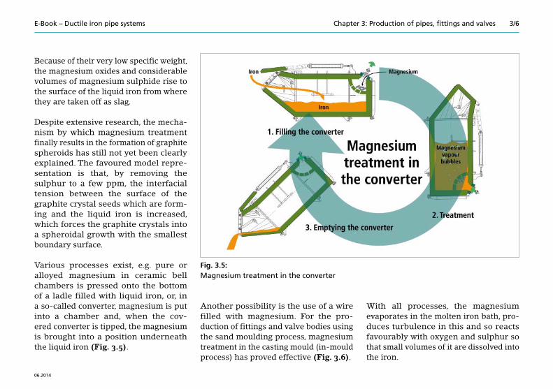
Because of their very low specific weight, the magnesium oxides and considerable volumes of magnesium sulphide rise to the surface of the liquid iron from where they are taken off as slag.
Despite extensive research, the mecha-nism by which magnesium treatment finally results in the formation of graphite spheroids has still not yet been clearly explained. The favoured model repre- sentation is that, by removing the sulphur to a few ppm, the interfacial tension between the surface of the graphite crystal seeds which are form-ing and the liquid iron is increased, which forces the graphite crystals into a spheroidal growth with the smallest boundary surface.
Various processes exist, e.g. pure or alloyed magnesium in ceramic bell chambers is pressed onto the bottom of a ladle filled with liquid iron, or, in a so-called converter, magnesium is put into a chamber and, when the cov- ered converter is tipped, the magnesium is brought into a position underneath the liquid iron (Fig. 3.5).
With all processes, the magnesium evaporates in the molten iron bath, pro-duces turbulence in this and so reacts favourably with oxygen and sulphur so that small volumes of it are dissolved into the iron.
Fig. 3.5: Magnesium treatment in the converter

3/7E-Book – Ductile iron pipe systems
06.2014
Chapter 3: Production of pipes, fittings and valves
Essentially, two working methods are used:
1) Centrifuging in metal moulds (mould- spinning moulds) according to the De Lavaud process (Fig. 3.7) and2) Centrifuging in metal moulds with linings according to the wet-spray process.
With both processes, the outside contour of the pipe is produced by a metal mould (spinning mould). The mould is located in a machine housing which can move longitudinally. At a number of points it rests on rollers and is held in place by pressure rollers on the top. Water is used for cooling from the outside. Driven by an electric motor, the mould rotates around its longitudinal axis. The internal profile of the mould determines the external shape of the pipe. In the widening of the mould on the socket side, a core formed according to the internal profile of the pipe socket, produced from sand and a binder, is inserted. At the same time this core closes off the mould.
3.3 Casting process
3.3.1 Pipe production using the centrifugal casting process
The notion of producing pipes by centri-fuging cast iron in metal moulds dated back to a patent by an engineer called Eckhardt in the year 1809. However, because there was little need for it and because of insufficient technical con-ditions, this invention was not able to be implemented. A particular difficulty lay in the distribution of the liquid iron in the casting mould rotating about its horizontal axis.
In 1910 Otto Briede from Benrath invent-ed the moving casting machine. His idea was put into practice by the Brazilian, de Lavaud, after whom the “De Lavaud process“ for the centrifugal casting of pipes used right across the world today is named. Centrifuged iron pipes were produced in Germany for the first time in 1926.
Fig. 3.6: Reaction of the liquid iron during magnesium treatment

3/8E-Book – Ductile iron pipe systems Chapter 3: Production of pipes, fittings and valves
06.2014
On the spigot-end side of the mould a collar is applied which corresponds approximately to the wall thickness of the pipe. The casting machine equipped in this way is tilted towards the socket side and is arranged on rails so that it can be moved longitudinally. At the upper end of the frame is the casting device with the distribution ladle which can take the volume of liquid iron for one or more pipes. A controlled, even speed of tilting means that during the casting process a
constant volume of iron per unit of time flows over the pouring lip of the distri- bution ladle into the pouring nozzle and from there out into the pouring trough. At the beginning of casting the trough proj-ects into the mould almost to the end of the socket. Before the iron starts to flow, the mould is put into rotation. The iron flowing out at the tip of the pouring trough is captured by the rotating mould, first filling the space between the socket core and the mould and then forming the
barrel of the pipe as a result of centrifu-gal force as the casting machine moves longitudinally (Fig. 3.8).
Because of the interaction of movements, the iron is laid down on the wall of the mould in a helix which, in the liquid state, merges into a homogenous pipe. A thicker or thinner pipe wall is produced by changing the volume of iron for the casting process.
Fig. 3.7: Centrifugal casting machine – pipe centrifuging process in metal moulds according to de Lavaud
Video 03.02: Centrifugal casting machine – animation
Fig. 3.8: Pouring trough retracted from the mould

3/9E-Book – Ductile iron pipe systems
06.2014
Chapter 3: Production of pipes, fittings and valves
carried away with them will, because of their weight, be forced inwards and are easy to remove during later cleaning. Because of the speed of cooling and the reduction in volume of the liquid iron occurring on solidification, the pipe comes away from the wall of the mould and can be pulled out mould on the socket side (Fig. 3.9).
The speed of rotation of the mould is selected so that a centrifugal force of 15 g to 30 g is exerted on the liquid iron. Because of the centrifugal force and because of the directional solidi- fication of the pipe wall from the mould side to the inside of the pipe, a particularly dense structure is produced. The centrifugal force has a further effect in that the oxidation products produced during the casting process and any slag
3.3.2 De Lavaud process
With this process, the mould is cooled from outside with water. Its inside sur-face is peened to produce ball-shaped depressions. This cold-peening in- creases the strength of the surface and helps the liquid iron to be taken up with the rotation movement of the mould. In this way, the iron pipes spun in metal moulds take on the surface typical of them. During or shortly before the pouring process, an inoculation powder is scattered into the mould. The process allows for extremely short cycle times because the pipe solidifies very quickly and can be removed within a few seconds; the next pipe can be cast immediately afterwards (Fig. 3.10).
In the non-lined moulds of the de Lavaud process, the surface of the mould is sub-jected to considerable thermal stresses due to temperature changes:n outside which, in comparison to the
inside surface, is only subject to a slightly fluctuating water temperature,
n inside, with the casting temperature of the molten iron, around 1,300 °C.
Fig. 3.10: Solidified pipe is pulled out of the mould
Fig. 3.9: Iron pipe is pulled out of the casting machine socket-end first
3/10E-Book – Ductile iron pipe systems Chapter 3: Production of pipes, fittings and valves
06.2014
Between two casting operations, the inside temperature can drop to 200 °C and below. The stress on the mould caused by this unabsorbed temperature change is accordingly high, which explains its limit-ed working life.
3.3.3 Wet-spray process
With the wet-spray process the mould is given an approximately 0.5 mm thick layer of lining. This layer (quartz powder bonded with bentonite) is wet-sprayed onto the mould before each casting pro-cess. The process comes from an English-speaking area and bears the widely used name wet-spray.
The thin lining reduces the amplitudes of the temperature change in the wall of the mould, which favours the working life of the mould. However, the lining has to be renewed after each casting; this extends the cycle time accordingly.
3.3.4 Older pipe production methods no longer in general use
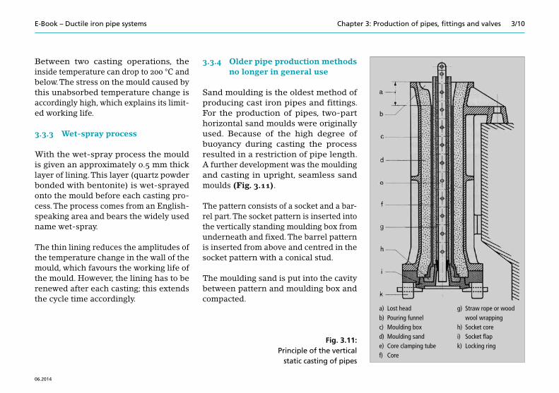
Sand moulding is the oldest method of producing cast iron pipes and fittings. For the production of pipes, two-part horizontal sand moulds were originally used. Because of the high degree of buoyancy during casting the process resulted in a restriction of pipe length. A further development was the moulding and casting in upright, seamless sand moulds (Fig. 3.11).
The pattern consists of a socket and a bar-rel part. The socket pattern is inserted into the vertically standing moulding box from underneath and fixed. The barrel pattern is inserted from above and centred in the socket pattern with a conical stud.
The moulding sand is put into the cavity between pattern and moulding box and compacted.
a) Lost head b) Pouring funnel c) Moulding box d) Moulding sande) Core clamping tube f) Core
g) Straw rope or wood wool wrapping
h) Socket core i) Socket flap k) Locking ring
Fig. 3.11: Principle of the vertical
static casting of pipes

3/11E-Book – Ductile iron pipe systems
06.2014
Chapter 3: Production of pipes, fittings and valves
3.3.5 Production of flanged pipes
Flanged pipes (Fig. 3.13) with shorter overall lengths are mainly produced in two-part horizontal moulds (dou-ble flanged pipe). In addition there are flanged pipes which are produced by pre-welding or screwing cast iron flanges onto spun cast iron pipes. Also shrink-fitting and welding is common practice (Fig. 3.14).
In order to increase productivity, these standing moulds were arranged in carousels (Fig. 3.12). Depending on the design of the moulds and cores, straight pipes or pipes with up to two sockets or flanges could be produced.
3.3.6 Production of fittings and valve bodies using the sand casting process
Using the centrifugal casting process it is only possible to produce rotationally symmetrical articles with cylindrical to conical external contours. Components with curves, branches or a number of connections (sockets or flanges) as well as valve bodies require a different form-ing process.
Fig. 3.12: A view inside the foundry hall with a pipe casting carousel
Fig. 3.13: Double flanged pipe DN 150/500 with integral cast-on flanges
Fig. 3.14: Detailed view of the shrink fit after cutting open

3/12E-Book – Ductile iron pipe systems Chapter 3: Production of pipes, fittings and valves
06.2014
For this purpose, patterns in metal, plastic or wood are used which completely map the external contour of the component. With these patterns, moulds are pro- duced from pure quartz sand mixed with a binder as the negative for the exter- nal contour of the component. This sand mould withstands the pressure and the temperature of the liquid iron until it has solidified. After that the sand mould is crushed and the sand is used again in the cycle. The mould is “lost” with each casting.
The internal contour of the casting is also mapped in this process, whereby the quartz sand for the “core” required here usually gets its strength from an organic binder. The cores must also resist the cast- ing temperature of more than 1,300 °C. Nevertheless they must yield to the shrinkage pressure during solidification so that the hollow part does not tear on the core during shrinking. Finally, they should also be easy to remove after the casting has cooled. As the cast metal solidifies, it burns the binder, the core loses its cohesion and the loose sand can be removed from the cooled casting.
Figure 3.15 shows a production line for fittings with lost cores. Figures 3.16, 3.17 and 3.18 show examples of the prepara-tory work for the production of fittings with lost cores.
Fig. 3.15: Production of fittings with lost cores
Fig. 3.16: Pattern for the production of the sand mould
Fig. 3.17: Sand mould prepared for the insertion of the lost core

3/13E-Book – Ductile iron pipe systems
06.2014
Chapter 3: Production of pipes, fittings and valves
Castings produced in high volumes are cast using moulding machines. The patterns are made of plastic or metal. The preferred mould material is clay-bonded quartz sand with additives, usually carbon dust. The mould material is compacted by shaking, pressing or shooting. Another method uses boxless moulds. In this case a hardening sand-synthetic resin mixture forms the mould material.
3.4 Post-treatment
Post-treatment refers to all processes on pipes, fittings and valve bodies which are performed after casting.
3.4.1 Subsequent heat treatment
Some of the production processes described for pipeline components make subsequent heat treatment necessary.
The reason for this is that the solid-state carbon dissolved in the liquid iron is either separated as elementary graphite or remains dissolved in the iron.
The higher the speed of cooling, the higher is the proportion of dissolved carbon in the iron (cementite). This structure has a high degree of hardness and a low elongation after fracture. A subsequent annealing process breaks down the cementite into ferrite and graphite, whereby the form of the graphite in ductile cast iron is spheroidal.
Also there is the vacuum moulding process. Here the strength of the mould sand, without binder, is achieved by negative pressure.
Smaller series and larger castings are produced in individual mould boxes, where a so-called sand slinger is used for compacting the moulding sand. It centrifuges the moulding material at high speed onto the pattern and the sand with which it is already filled. This solidifies the sand-clay mixture. The patterns are made of wood or plastic.
Cores for fittings and valves are mainly produced from quartz sand with cold or hot hardening binders. They must be stable enough to resist the casting pressure which, because of the density of the iron, reaches around 1 bar even with a static casting height of 1.40 m. In general it is the case that the sand moulding process allows an almost unrestricted freedom of design for components.
Fig. 3.18: Lost core inserted in the sand mould
3/14Chapter 3: Production of pipes, fittings and valves
06.2014
E-Book – Ductile iron pipe systems
3.4.2 Fettling and mechanical processing
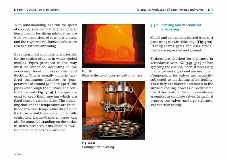
Mould and core sand is blasted from cast parts using cut wire (blasting) (Fig. 3.20). Casting seams, gates and riser attach-ments are separated and ground.
Fittings are checked for tightness in accordance with EN 545 [3.1] before applying the coating. Then, if necessary, the flange and spigot end are machined. Components for valves are generally subjected to machining after fettling. Then they are blasted and taken to the surface coating process directly after this. After coating the components are assembled as complete valves. In the final process the valves undergo tightness and function testing.
With sand moulding, as a rule the speed of cooling is so low that after solidifica-tion a broadly ferritic-graphitic structure with low proportions of pearlite is present and the required mechanical values are reached without annealing.
By contrast, fast cooling is characteristic for the casting of pipes in water-cooled moulds. Pipes produced in this way must be annealed, according to the necessary level of workability and ductility. This is usually done in gas- fired continuous furnaces. At tem- peratures of around 920 °C to 950 °C, the pipes rollthrough the furnace at a con-trolled speed (Fig. 3.19). Carriages are used to keep them moving which are fixed onto a transport chain. The annea-ling time and the temperature are estab- lished in a time-temperature diagram for the furnace and these are automatically controlled. Large-diameter pipes can also be annealed standing on the socket in batch furnaces. This enables oval- isation of the pipes to be avoided.
Fig. 19: Pipes in the continuous annealing furnace
Fig. 3.20: Castings after blasting

3/15E-Book – Ductile iron pipe systems
06.2014
Chapter 3: Production of pipes, fittings and valves
3.5 Application of coatings and linings
3.5.1 Pipes
Zinc or zinc-aluminium coating with protective finishing layer
The zinc or zinc-aluminium coating is applied to the pipes after they have been heat-treated. With metallic zinc spraying, zinc wire (minimum purity 99.99 %) or zinc-aluminium wire (Zn85Al15) is molten in a flame or in an electric arc. The fine metallic drops are blasted at high speed onto the surface to be coated. This happens in automatically operating equipment; for example the spray gun moves along the rotating pipe. In this way the zinc or zinc-aluminium coating is applied in a helix shape (Fig. 3.21).
Straight after zinc or zinc-aluminium coating, the pipes are checked for dimen-sional accuracy and tightness tested on fully automated testing and fettling lines. Also included in this type of protection of the pipes is a finishing layer which is applied to the rotating pipe. The inside of the socket is given separate treatment here.
The zinc or zinc-aluminium coating for pipes in ductile cast iron is standardised in EN 545 [3.1] and EN 598 [3.2].
Cement mortar coating
Cement mortar coating is a multi-layer coating for pipes with the following layer structure (Fig. 3.22):n zinc coating, n with or without primer layer (two-component synthetic resin coating),n cement mortar layer.
The cement mortar layer is a layer of fibrous cement mortar based on blast-furnace cement, which can be polymer-modified, pigmented and wrapped with a bandage material. The primer layer may be omitted if a polymer-modified cement mortar is used. The fibres mixed with the mortar may be glass or plastic fibres. For the application of the cement mortar coating, there are two processes in use. What the two processes have in common is that a certain amount of fibres cut to length are mixed into the polymer- modified mortar which comes out of the compulsory mixer. The mortar is then pumped to a circular spray nozzle (spraying process) or a flat die (extrusion process).
Fig. 3.21: Applying the zinc-aluminium coating

3/16E-Book – Ductile iron pipe systems Chapter 3: Production of pipes, fittings and valves
06.2014
With the spraying process the mortar is sprayed onto the rotating pipe using compressed air (Fig. 3.23). The spray nozzle is mounted on a support and travels slowly along the pipe. A smoothing mechanism then reduces the cement mortar coating to the specified layer thickness.
With the extrusion process, the cement mortar comes out of a stationary flat die and winds an even layer thickness in bands around the rotating pipe as it slowly travels past the nozzle. Syn- chronous with the application of the mortar, this also receives a bandage of PE net tissue. At almost the same time as the bandaging, a smoothing mecha-nism which is also set up to be stationary then smoothes the surface of the mortar. After this stage, the PE net tissue is completely covered with a thin layer of mortar (Fig. 3.24).
Fig. 3.24: Cement mortar coating – extrusion process
Fig. 3.23: Spraying process
Fig. 3.22: Layer structure of a pipe with cement mortar coating and cement mortar lining

3/17E-Book – Ductile iron pipe systems
06.2014
Chapter 3: Production of pipes, fittings and valves
With both processes, mortar flow rate, pipe rotation speed and speed of travel are to be coordinated in such a way that the nominal coating thickness for the cement mortar coating keeps to a value of 5 mm over the entire length of the pipe barrel. The end face of the socket and the spigot end of the pipe remain free of cement mortar. These parts also have a zinc coating and, after the cement mortar coating has set, they are provided with a finishing layer.
The cement mortar coating of ductile cast iron pipes is standardised in EN 15542 [3.3]. According to EN 545 [3.1] these pipes can be installed in soils of any level of corrosiveness.
Polyurethane coating
The polyurethane (PUR) used is a solvent- free two-component system with resin and hardening agent. Polyurethane, mineral fillers, pigments and additives are selected in such a way that the end product meets the functional require-ments set and the drinking water regulations. Before applying the PUR coating, the surface of the pipe is cleaned
so that it is technically clean, free of rust, loose particles of material, dirt, oil, grease and moisture. In order to meet these requirements, the surface of the pipes is blasted to preparation grade SA 2 1/2 as per EN ISO 8501-1 [3.4]. The pipes are first heated to about 50 °C in order to ensure an acceleration of the polymerisation of the components to a mechanically resilient coating. The polyurethane is then sprayed onto the rotating pipe (Fig. 3.25). The pore-free PUR coating is applied to the entire pipe barrel continuously from the end face of the socket up to and including the spigot end. After the coating process the coating is also checked to ensure that it is free of pores.
The PUR coating has a uniform and even appearance in terms of colour, smooth-ness and structure. Adhesive strength, freedom from porosity, hardness and coating thickness are checked daily in production (Fig. 3.26).
Fig. 3.25: Applying the black PUR coating
Fig. 3.26: Ductile iron pipe with polyurethane coating and polyurethane lining

3/18E-Book – Ductile iron pipe systems Chapter 3: Production of pipes, fittings and valves
06.2014
The PUR coating of ductile iron pipes is standardised in EN 15189 [3.5]. According to EN 545 [3.1] these pipes can be installed in soils of any level of corrosiveness.
Polyethylene coating
The polyethylene coating consists of LDPE (low density polyethylene). It is applied to the pipe using a soft adhesive; up to and including DN 500 this is done using the tubular extrusion process, as from and including DN 400 using the flat die wrapping extrusion process.
The PE coating of ductile iron pipes is standardised in EN 14628 [3.6]. Accord-ing to EN 545 [3.1] these pipes can be installed in soils of any level of corrosive-ness.
Cement mortar lining
In the centrifugal rotation process, after the application of the fresh mortar (sand-cement-water mixture) the pipe is brought to a sufficiently high speed of rotation so that the centrifugal accel-eration is at least twenty times gravita-
tional acceleration. With this acceleration and with additional vibration forces, the fresh mortar undergoes compaction and smoothing (Fig. 3.27).
With centrifugal rotation, part of the mixing water is driven out. A concen-tration of fine grains and fine ele-ments occurs towards the surface of the cement mortar lining. The cement mortar lining hardens in curing chambers at a defined air humidity and temperature. The cement mortar lining of ductile iron pipes is stand- ardised in EN 545 [3.1] and EN 598 [3.2].
Polyurethane lining
The polyurethane used is a solvent-free two-component system with resin and hardening agent. Mineral fillers, pig-ments and additives are selected in such a way that the end product meets the func-tional requirements set and the drinking water regulations (e.g. DVGW). Before applying the PUR lining, the inside sur-face of the pipe is cleaned so that it is technically clean, free of rust, loose particles of material, dirt, oil, grease and moisture. In order to meet these
requirements the inside surface of the pipe is ground and double-blasted to preparation grade SA 2 1/2 as per EN ISO 8501-1 [3.4]. The pipes are first heated to about 50 °C in order to ensure an acceleration of the polymerisation of the components. This means that short cycle times can be achieved in the coating process.
Fig. 3.27: Centrifugal rotation – applying a cement mortar lining

3/19E-Book – Ductile iron pipe systems
06.2014
Chapter 3: Production of pipes, fittings and valves
The polyurethane is then sprayed onto the rotating pipe using a lance with a rotating nozzle (Fig. 3.28). The centri-fugal force produced by the rotation of the pipe itself results in a very smooth surface which has good hydraulic proper-ties. The pore-free polyurethane lining is applied continuously to the whole of the pipe surface.
The inside of the socket is also lined with polyurethane. In combination with the PUR lining, an iron pipe is also provided with integral corrosion protection.
After the coating process the lining is checked to ensure that it is free of pores. The PUR lining has a uniform and even appearance in terms of colour, smoothness and structure. Adhesive strength, freedom from porosity, hard-ness and coating thickness are checked daily in production.
The polyurethane lining of ductile iron pipes is standardised in EN 15655 [3.7].
3.5.2 Fittings and valves
Epoxy resin coating
As is the case with valves, the powder coat- ing of fittings with epoxy resin is becom-ing increasingly important. According to EN 545 [3.1], fittings coated in this way are suitable for soils of all classes of aggres-siveness. The same also applies to valves coated with fusion bonded epoxy.
To achieve this, the castings first of all undergo surface treatment in the form of blasting (preparation grade SA 2 1/2). The castings are then heated to an object temperature of approximately 200 °C and dipped into a fluidised bed with epoxy resin powder (Fig. 3.29) or coated electro-statically using a spray gun (Fig. 3.30).
This produces pore-free coatings with layer thicknesses of more than 250 μm. Depending on the type of equipment used, the coating process may be automated. Continuous monitoring of the coating as regards cross-linking, mechanical properties, disbonding and coating thickness ensures constant quality.
Fig. 3.28: Applying the PUR lining using a lance with rotating nozzle

3/20E-Book – Ductile iron pipe systems Chapter 3: Production of pipes, fittings and valves
06.2014
The epoxy powder coating of ductile iron fittings is standardised in EN 14901 [3.8] and RAL GZ 662 [3.9]. The epoxy coat-ing of valve bodies is standardised in DIN 30677-1 [3.10], DIN 30677-2 [3.11], DIN 3476 [3.12] and RAL GZ 662 [3.9].
Cement mortar lining
Fittings are lined with cement mortar using the projection process in accord-ance with EN 545 [3.1] and EN 598 [3.2]. In this process a worm pump is used to pump the cement mortar through a tube and then through a rotating projection head driven by compressed air onto the wall of the pipe, thereby compacting it. After curing at defined conditions the fittings then undergo further processing.
Depending on the particular case, blast furnace cement is generally used here. With this type of mortar application it is not possible for excess water to be driven out; the preparation of the mortar using the necessarily low water-cement ratio is made possible by the addition of a syn-thetic resin emulsion.
Depending on the nominal size, the total coating thickness is 2.5 mm to 9 mm.
As an external coating, fittings lined with cement mortar are usually provided with a 70 μm bitumen coating. In individual cases a two-component zinc rich paint and a bitumen finishing layer are also used.
The cement mortar lining of ductile iron fittings is standardised in EN 545 [3.1] and EN 598 [3.2].
Fig. 3.29: Epoxy powder applied by robots in the fluidised bed process
Fig. 3.30: Electrostatic application of epoxy powder with a spray gun

3/21E-Book – Ductile iron pipe systems
06.2014
Chapter 3: Production of pipes, fittings and valves
Technical enamelling
Vitreous enamel as a coating material tends to be used in places where vessels, pipes, fittings and valves need to be protected against chemical exposure and in some cases also extreme conditions (Fig. 3.31).
With ductile cast iron as the base material, vitreous enamel produces a combination which offers a range of significant prop-erties, for example:n a smooth, anti-adhesive surface,n a high degree of hardness,n a glass-like, fully inorganic structure,n a high chemical resistance.
The castings are often annealed before enamelling in order to improve con-ditions for enamelling.
After the annealing process the surface is blasted (EN ISO 12944-4 [3.13]; SA 2 1/2). Blasting cleans and activates the surface and produces a certain degree of sur-face roughness. In addition the specific surface is increased. This means that it meets the conditions for material bonding in the following enamelling process.
The basic material consists of so- called enamel frits. These are produced by smelting (at over 1,200 °C) and then quenching and breaking up natural inorganic materials including quartz, feldspar, borax, soda, potash, aluminium oxide and other metal oxides. The enamel frits are milled with additives and water to produce an enamel slip.
The slip is applied to the casting by dipping, pouring (Fig. 3.32) or spraying (Fig. 3.33) and then dried at ≤ 110 °C. This is then followed by the actual firing process, in a temperature range of between 750 °C and 900 °C depending on the quality of the enamel.
Fig. 3.31: Fitting coated outside and inside with enamel
Fig. 3.32: Applying enamel by pouring

3/22E-Book – Ductile iron pipe systems Chapter 3: Production of pipes, fittings and valves
06.2014
The enamelling of ductile cast iron fittings and valves is standardised in DIN 51178 [3.14]. A detailed description of the enamelling technique can be found in Chapter 7.2.
3.6 Marking
3.6.1 Marking of pipes and fittings in ductile cast iron
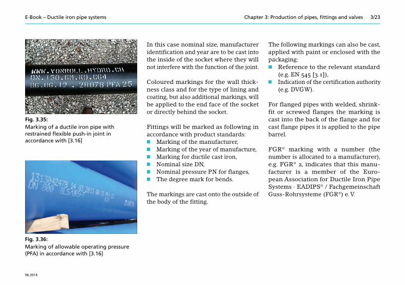
The marking of pipes and fittings (Fig.3.34) is defined in product stand- ards EN 545 [3.1] and EN 598 [3.2] and also in EADIPS®/FGR® - Standard 33 [3.15]. The marking of allowable operating pressures (PFA) for the restrained flexible push-in joints of pipes is covered in EADIPS®/FGR® - Standard 75 [3.16] (Figs. 3.35 and 3.36).
The marking of material, production date and nominal size is cast into or onto the product.
The marking of the material as “ductile cast iron”, which must also be visible after installation, consists of three raised or recessed points arranged in a triangle or three parallel, notch-shaped depressions on the end face of the socket.
For socket pipes produced by means of the centrifugal casting process, the marking is basically applied to the socket.
Fig. 3.33: Applying enamel by spraying
Fig. 3.34: Examples of the labelling of ductile fittings
3/23E-Book – Ductile iron pipe systems
06.2014
Chapter 3: Production of pipes, fittings and valves
Fig. 3.35: Marking of a ductile iron pipe with restrained flexible push-in joint in accordance with [3.16]
Fig. 3.36: Marking of allowable operating pressure (PFA) in accordance with [3.16]
In this case nominal size, manufacturer identification and year are to be cast into the inside of the socket where they will not interfere with the function of the joint.
Coloured markings for the wall thick-ness class and for the type of lining and coating, but also additional markings, will be applied to the end face of the socket or directly behind the socket.
Fittings will be marked as following in accordance with product standards:n Marking of the manufacturer,n Marking of the year of manufacture,n Marking for ductile cast iron,n Nominal size DN,n Nominal pressure PN for flanges,n The degree mark for bends.
The markings are cast onto the outside of the body of the fitting.
The following markings can also be cast, applied with paint or enclosed with the packaging:n Reference to the relevant standard
(e.g. EN 545 [3.1]),n Indication of the certification authority
(e.g. DVGW).
For flanged pipes with welded, shrink- fit or screwed flanges the marking is cast into the back of the flange and for cast flange pipes it is applied to the pipe barrel.
FGR® marking with a number (the number is allocated to a manufacturer), e.g. FGR® 2, indicates that this manu- facturer is a member of the Euro-pean Association for Ductile Iron Pipe Systems · EADIPS® / Fachgemeinschaft Guss-Rohrsysteme (FGR®) e. V.
3/24E-Book – Ductile iron pipe systems Chapter 3: Production of pipes, fittings and valves
06.2014
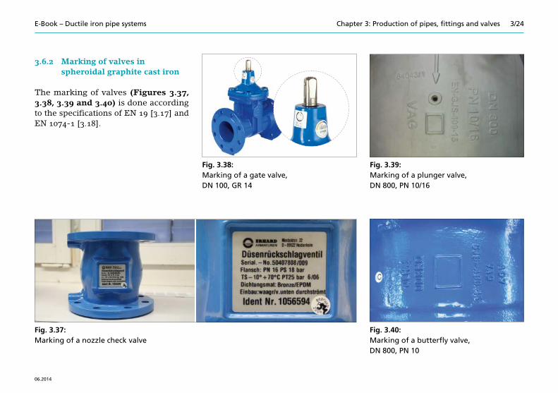
3.6.2 Marking of valves in spheroidal graphite cast iron
The marking of valves (Figures 3.37, 3.38, 3.39 and 3.40) is done according to the specifications of EN 19 [3.17] and EN 1074-1 [3.18].
Fig. 3.38: Marking of a gate valve, DN 100, GR 14
Fig. 3.39: Marking of a plunger valve, DN 800, PN 10/16
Fig. 3.40: Marking of a butterfly valve, DN 800, PN 10
Fig. 3.37: Marking of a nozzle check valve

3/25E-Book – Ductile iron pipe systems
06.2014
Chapter 3: Production of pipes, fittings and valves
3.7 Testing
3.7.1 Testing the pipe
After the annealing process and after tightness testing, ductile iron pipes with or without zinc coating undergo dimen- sional checking on combined fettling and testing lines. In addition, they are checked for any flaws outside and inside by means of visual inspection. For example, wall thickness measurements are taken with quick-test gauges. The sockets and spigot ends are checked with limit gauges. Hardness testing is carried out for a subsequent assessment of the annea-ling process. An evaluation of ferrite levels and ductility (elongation after fracture) is provided by the ring flattening test (defor-mation of a ring cut from the pipe) on the fettling and testing line; compact-ability is a reference value for ductility.
Instead of the ring flattening test, a ball indentation test can also be carried out. The precise mechanical strength values (tensile strength, 0.2 % yield point, elongation after fracture and Brinell hardness) are determined in mate-
rial testing laboratories. These values are to be tested on cylindrical test bars machined from the pipe wall.
The requirements for the lining and the tests which need to be carried out are defined in EN 545 [3.1] and EN 598 [3.2]. Regular testing in the con-text of certification ensures consistent quality, as in e.g. DVGW test specifi- cation GW 337 [3.19] and DVGW supple-ment GW 337-B1 [3.20].
3.7.2 Testing fittings and valves
For castings, fittings and valve bodies produced in sand moulds, similar testing criteria to those for pipes apply. However, unlike the procedure for pipes, with fittings the specimens cannot be taken from the casting itself without destroy-ing it. Mechanical properties are tested on cylindrical test bars taken from separately cast U or Y specimens; hard-ness can be measured on the casting itself. For the quick-test for ductility, sound velocity measurement is carried out using ultrasound, either on a separately cast test bar or on the casting itself.
Tightness and function tests on fittings and valves are incorporated at an appro-priate point in the overall course of their production. This also applies to all testing of material properties, dimensions and other criteria as required in the product and coating standards for process control.
Depending on the agreement reached, the results of the testing of pipes, fittings and valves are recorded in a works certificate or an acceptance certificate in accordance with EN 10204 [3.21].

3/26E-Book – Ductile iron pipe systems Chapter 3: Production of pipes, fittings and valves
06.2014
3.8 References
[3.1] EN 545 Ductile iron pipes, fittings, accessories and their joints for water
pipelines – Requirements and test methods [Rohre, Formstücke, Zubehörteile
aus duktilem Gusseisen und ihre Verbindungen für Wasserleitungen –
Anforderungen und Prüfverfahren] 2010
[3.2] EN 598 Ductile iron pipes, fittings, accessories and their joints for
sewerage applications – Requirements and test methods [Rohre, Formstücke, Zubehörteile
aus duktilem Gusseisen und ihre Verbindungen für die Abwasser-Entsorgung –
Anforderungen und Prüfverfahren] 2007+A1:2009
[3.3] EN 15542 Ductile iron pipes, fittings and
accessories – External cement mortar coating for pipes – Requirements and test methods [Rohre, Formstücke und Zubehör
aus duktilem Gusseisen – Zementmörtelumhüllung von Rohren – Anforderungen und Prüfverfahren] 2008
[3.4] EN ISO 8501-1 Preparation of steel substrates
before application of paints and related products –
Visual assessment of surface cleanliness – Part 1: Rust grades and preparation
grades of uncoated steel substrates and of steel substrates after overall removal of previous coatings
(ISO 8501-1:2007)
[Vorbereitung von Stahloberflächen vor dem Auftragen von
Beschichtungsstoffen – Visuelle Beurteilung der Oberflächenreinheit – Teil 1: Rostgrade und Oberflächen-
vorbereitungsgrade von unbeschichteten Stahloberflächen
und Stahloberflächen nach ganz-flächigem Entfernen vorhandener Beschichtungen (ISO 8501-1:2007)]
2007
[3.5] EN 15189 Ductile iron pipes, fittings and
accessories – External polyurethane coating for pipes – Requirements and test methods [Rohre, Formstücke und Zubehör
aus duktilem Gusseisen – Polyurethanumhüllung von Rohren – Anforderungen und Prüfverfahren] 2006

3/27E-Book – Ductile iron pipe systems
06.2014
Chapter 3: Production of pipes, fittings and valves
[3.6] EN 14628 Ductile iron pipes, fittings and accessories – External polyethylene coating for pipes – Requirements and test methods [Rohre, Formstücke und Zubehör-
teile aus duktilem Gusseisen – Polyethylenumhüllung von Rohren –
Anforderungen und Prüfverfahren] 2005
[3.7] EN 15655 Ductile iron pipes, fittings and accessories – Internal polyurethane lining for pipes and fittings – Requirements and test methods [Rohre, Formstücke und Zubehör-
teile aus duktilem Gusseisen – Polyurethan-Auskleidung von
Rohren und Formstücken – Anforderungen und Prüfverfahren] 2009
[3.8] EN 14901 Ductile iron pipes, fittings and
accessories – Epoxy coating (heavy duty) of ductile iron fittings and accessories –
Requirements and test methods [Rohre, Formstücke und Zubehör
aus duktilem Gusseisen – Epoxidharzbeschichtung (für
erhöhte Beanspruchung) von Formstücken und Zubehörteilen aus duktilem Gusseisen – Anforderungen und Prüfverfahren] 2006
[3.9] RAL – GZ 662 Güte- und Prüfbestimmungen Schwerer Korrosionsschutz von
Armaturen und Formstücken durch Pulverbeschichtung
[Heavy duty corrosion protection of valves and fittings by powder
coating – Quality aussurance] 2008
[3.10] DIN 30677-1 Äußerer Korrosionsschutz von erdverlegten Armaturen; Umhüllung (Außenbeschichtung)
für normale Anforderungen [Corrosion protection of buried valves; coating for normal requirement] 1991
[3.11] DIN 30677-2 Äußerer Korrosionsschutz von erdverlegten Armaturen; Umhüllung aus Duroplasten
(Außenbeschichtung) für erhöhte Anforderungen
[External corrosion protection of buried valves; heavy-duty thermoset plastics coatings] 1988

3/28E-Book – Ductile iron pipe systems Chapter 3: Production of pipes, fittings and valves
06.2014
[3.12] DIN 3476 Armaturen und Formstücke für Roh- und Trinkwasser – Korrosionsschutz durch EP-Innen-
beschichtung aus Pulverlacken (P) bzw. Flüssiglacken (F) –
Anforderungen und Prüfungen [Valves and fittings for untreated
and potable water – Protection against corrosion by
internal epoxy coating of coating powders (P) or liquid varnishes (F) –
Requirements and tests] 1996
[3.13] EN ISO 12944-4 Paints and varnishes - Corrosion pro-
tection of steel structures by protective paint systems – Part 4: Types of surface and surface
preparation (ISO 12944-4:1998) [Beschichtungsstoffe – Korrosions-
schutz von Stahlbauten durch Beschichtungssysteme – Teil 4: Arten von Oberflächen und
Oberflächenvorbereitung (ISO 12944-4:1998)] 1998
[3.14] DIN 51178 Emails und Emaillierungen – Innen- und außenemaillierte Armaturen und Druckrohr-
formstücke für die Roh- und Trinkwasserversorgung –
Qualitätsanforderungen und Prüfung [Vitreous and porcelain enamels – Inside and outside enamelled valves
and pressure pipe fittings for un- treated and potable water supply –
Quality requirements and testing] 2009-10
[3.15] EADIPS®/FGR® 33 Rohre und Formstücke aus duktilem Gusseisen – Kennzeichnung von Rohren und Formstücken [Ductile iron pipes and fittings – Marking of ductile iron pipes and fittings] 2013-06
[3.16] EADIPS®/FGR® 75 Rohre aus duktilem Gusseisen - Kennzeichnung des zulässigen Bauteilbetriebsdrucks (PFA)
längskraftschlüssiger beweglicher Steckmuffen-Verbindungen von Rohren –
Ergänzung zur EN 545:2010 [Ductile iron pipes - Marking of the allowable operating
pressure PFA of restrained flexible push-in socket joints of pipes – Supplement to EN 545:2010] 2013-06
[3.17] EN 19 Industrial valves – Marking of metallic valves [Industriearmaturen – Kennzeichnung von Armaturen aus Metall] 2002

3/29E-Book – Ductile iron pipe systems
06.2014
Chapter 3: Production of pipes, fittings and valves
[3.18] EN 1074-1 Valves for water supply – Fitness for purpose requirements
and appropriate verification tests – part 1: General requirements [Armaturen für die Wasser- versorgung – Anforderungen an die Gebrauchs-
tauglichkeit und deren Prüfung – Teil 1: Allgemeine Anforderungen] 2000
[3.19] DVGW-Arbeitsblatt GW 337 Rohre, Formstücke und Zubehör-
teile aus duktilem Gusseisen für die Gas- und Wasserversorgung –
Anforderungen und Prüfungen [DVGW worksheet GW 337 Ductile cast iron pipes, fittings and accessories for gas and water supply –
Requirements and tests] 2010-09
[3.20] DVGW-Arbeitsblatt GW 337-B1 Beiblatt 1 zu DVGW-Prüfgrundlage
GW 337 Rohre, Formstücke und Zubehörteile aus duktilem Gusseisen für die Gas- und Wasserversorgung – Anforderungen und Prüfungen
[DVGW worksheet GW 337-B1 Supplement 1 to DVGW test
specification GW 337 Ductile cast iron pipes, fittings and
accessories for gas and water supply – Requirements and tests]
2012-08
[3.21] EN 10204 Metallic products – Types of inspection documents [Metallische Erzeugnisse – Arten von Prüfbescheinigungen] 2004

3/30E-Book – Ductile iron pipe systems Chapter 3: Production of pipes, fittings and valves
06.2014