3 modeling - hps.hs-regensburg.de. dr. m. schubert vhdl practical training fh regensburg - modeling...
TRANSCRIPT
Prof. Dr. M. Schubert VHDL Practical Training FH Regensburg
- Modeling 3.1 -
3 Modeling VHDL distinguishes three possibilities of writing source code: 1. structural: instantiation of components, 2. concurrent: the sequence of source lines does not matter, no variables, 3. sequential: top-down processing of source lines, no signal declarations. This three options may be mixed, i.e. concurrent signal assignment statements, entity instantiations and processes or subprogram calls can be used together in the same architecture. The ASSERT statement is used to write messages, typically on the screen. It can be used in concurrent environment (concurrent assertion) and sequential environment (sequential assertion). BNF:
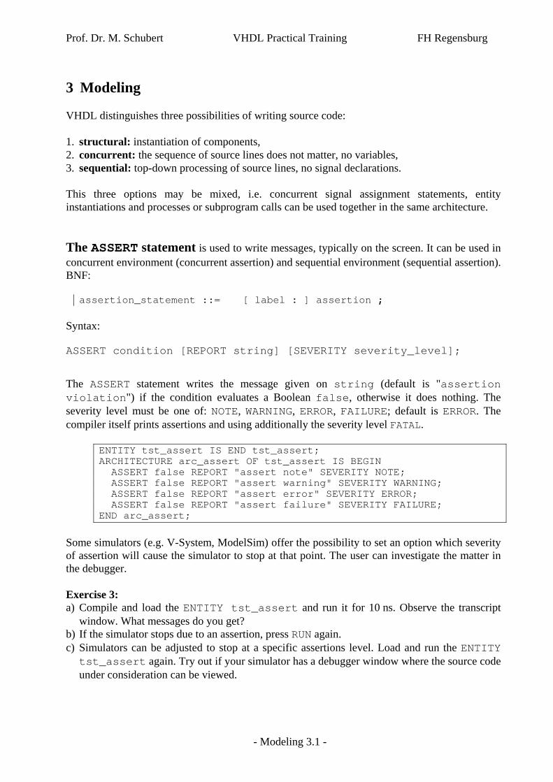
assertion_statement ::= [ label : ] assertion ; Syntax: ASSERT condition [REPORT string] [SEVERITY severity_level]; The ASSERT statement writes the message given on string (default is "assertion violation") if the condition evaluates a Boolean false, otherwise it does nothing. The severity level must be one of: NOTE, WARNING, ERROR, FAILURE; default is ERROR. The compiler itself prints assertions and using additionally the severity level FATAL.
ENTITY tst_assert IS END tst_assert; ARCHITECTURE arc_assert OF tst_assert IS BEGIN ASSERT false REPORT "assert note" SEVERITY NOTE; ASSERT false REPORT "assert warning" SEVERITY WARNING; ASSERT false REPORT "assert error" SEVERITY ERROR; ASSERT false REPORT "assert failure" SEVERITY FAILURE; END arc_assert;
Some simulators (e.g. V-System, ModelSim) offer the possibility to set an option which severity of assertion will cause the simulator to stop at that point. The user can investigate the matter in the debugger. Exercise 3: a) Compile and load the ENTITY tst_assert and run it for 10 ns. Observe the transcript
window. What messages do you get? b) If the simulator stops due to an assertion, press RUN again. c) Simulators can be adjusted to stop at a specific assertions level. Load and run the ENTITY tst_assert again. Try out if your simulator has a debugger window where the source code under consideration can be viewed.

Prof. Dr. M. Schubert VHDL Practical Training FH Regensburg
- Modeling 3.2 -
3.1 Structural Modeling
3.1.1 Entitys
Structural modeling is based on ENTITY Instantiation. This chapter presumes the knowledge of chapter 1. A complete description of the ENTITY statement is beyond the scope of this work. Example for an entity declaration:
LIBRARY ieee; USE ieee.std_logic_1164.ALL; ENTITY HalfAdder IS PORT( a,b: IN std_ulogic:='0'; s,c: OUT std_ulogic ); END HalfAdder;
Input signals may have defaults. In the example above the signals a and b will default to '0' instead of 'U'. Example for component declaration in the declaration region of an architecture:
COMPONENT HalfAdder IS PORT( a,b: IN std_ulogic:='0'; s,c: OUT std_ulogic ); END COMPONENT;
Example for an entity instantiation with positional signal association:
i_positional:HalfAdder PORT MAP(a0,b0,s0,c0);
Two examples for entity instantiations with named signal association:
i_named_1:HalfAdder PORT MAP(c=>c0,s=>s0,a=>a0,b=>b0); i_named_2:HalfAdder PORT MAP( c => c0, s => s0, a => a0, b => b0 );
Prof. Dr. M. Schubert VHDL Practical Training FH Regensburg
- Modeling 3.3 -
3.1.2 PORT Modes
Declarations in PORT statements are implicit signals declarations. This is because variables must not appear in PORTs and constants are realized by generics as detailed below. Signals in PORTs have one of the following modes: IN, OUT , INOUT, BUFFER. Mode functionality of PORT signal:
IN read only OUT write only, signal not readable inside the architecture INOUT read and write BUFFER like INOUT, but the signal may have only one driver, the effect is like mode
OUT but the signal may be read. 3.1.3 The OPEN keyword
The keyword OPEN models a port signal with no connection to the outer world. Example for a HalfAdder with unconnected input signal a:
i_unconnected_a: HalfAdder PORT MAP(c=>OPEN,s=>s0,a=>a0,b=>b0);
In the example above, the default value is used for signal a as it is not connected. Missing trailing signals in positional association are handled as implicit OPEN. In the following example the trailing carry output signal is missing and therefore modeled as OPEN.
i_ unconnected_c:HalfAdder PORT MAP(a0,b0,s0);
3.1.4 Generics
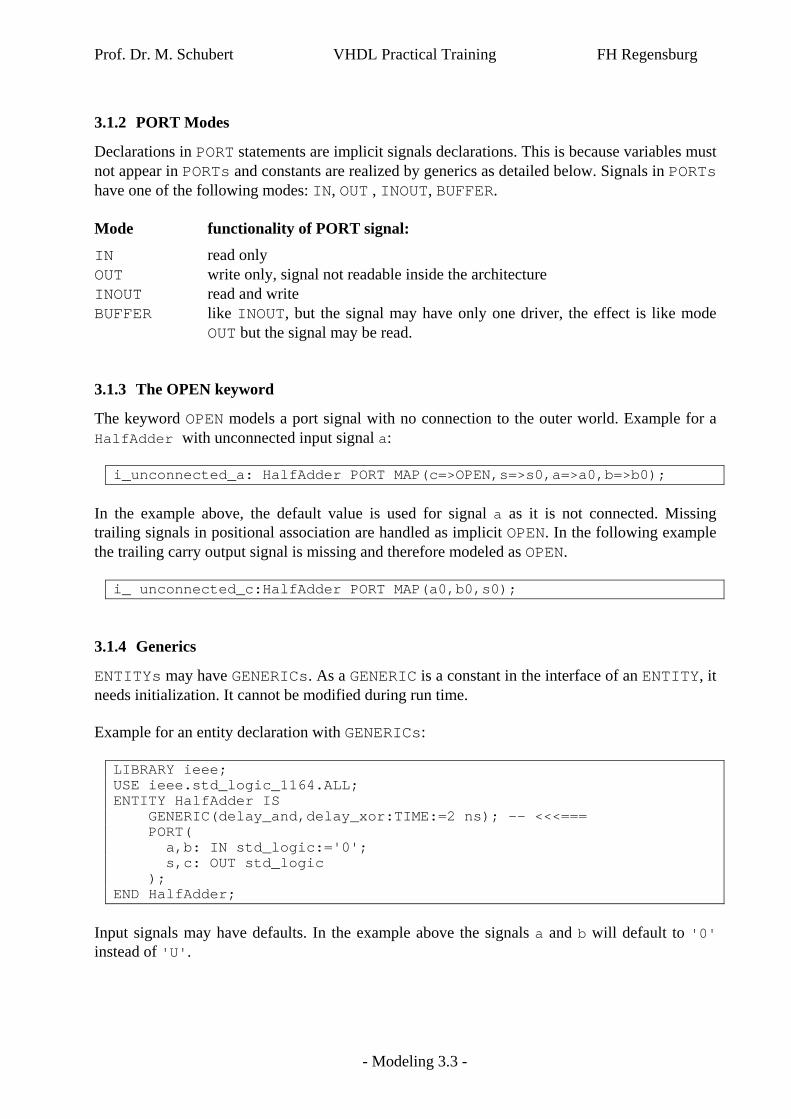
ENTITYs may have GENERICs. As a GENERIC is a constant in the interface of an ENTITY, it needs initialization. It cannot be modified during run time. Example for an entity declaration with GENERICs:
LIBRARY ieee; USE ieee.std_logic_1164.ALL; ENTITY HalfAdder IS GENERIC(delay_and,delay_xor:TIME:=2 ns); -- <<<=== PORT( a,b: IN std_logic:='0'; s,c: OUT std_logic ); END HalfAdder;
Input signals may have defaults. In the example above the signals a and b will default to '0' instead of 'U'.

Prof. Dr. M. Schubert VHDL Practical Training FH Regensburg
- Modeling 3.4 -
Example for component declaration in the declaration region of an architecture:
COMPONENT HalfAdder GENERIC(delay_and,delay_xor:TIME:=2 ns); -- <<<=== PORT( a,b: IN std_logic:='0'; s,c: OUT std_logic ); END COMPONENT;
Example for an entity instantiation with generics:
CONSTANT delay_xor:TIME:=3 ns; -- delay of an XOR gate … i_generic:HalfAdder GENERIC MAP(2 ns,delay_xor) PORT MAP(a,b,s,c);

Prof. Dr. M. Schubert VHDL Practical Training FH Regensburg
- Modeling 3.5 -
3.2 Concurrent Modeling
A digital circuit is by its nature concurrent because all signals in the circuit have a voltage level any time. The use of entities is a means of structuring and partitioning. Sequential code is „a normal, sequential programming language“ to internally describe external concurrent behavior. 3.2.1 Concurrent signal assignment
Inertial signal assignment schedules a maximum of one event. Pulses with a width less than the delay will be cancelled:
S_inertial <= a XOR b AFTER 2 ns; Transport signal assignment schedules an arbitrary number of events:
S_transport <= TRANSPORT a XOR b AFTER 10 ns; Zero-delay signal assignment schedules an event with one simulation delta () delay:
S_deltadelay <= a XOR b; 3.2.2 Conditional signal assignment:
SIGNAL condition,a,b,y :std_logic; … y <= a AFTER 1 ns WHEN condition='0' ELSE b AFTER 1 ns WHEN condition='1' ELSE 'X' AFTER 1 ns;
This construct contains priority coding selecting the 1st matching condition. It models a
multiplexer that consists of nested 2-input multiplexers. The compiler will generate an error when not all possible cases are satisfied. This is because
a driver (<=) cannot interrupt driving. 3.2.3 Selected signal assignment:
SIGNAL sel,a,b,y :std_logic ; … WITH sel SELECT y <= a AFTER 1 ns WHEN '0', b AFTER 1 ns WHEN '1', 'X' AFTER 1 ns WHEN OTHERS;
This construct models a multiplexer with equivalent inputs. The compiler will generate an error when not all possible cases are satisfied. This is because
a driver (<=) cannot interrupt driving.

Prof. Dr. M. Schubert VHDL Practical Training FH Regensburg
- Modeling 3.6 -
3.2.4 GENERATE Statement
The GENERATE statement is a concurrent loop construct. BNF:
generate_statement ::= generate_label : generation_scheme GENERATE [ { block_declarative_item } BEGIN ] { concurrent_statement } END GENERATE [ generate_label ] ;
Syntax with FOR loop: generate_label: FOR variable_name IN discrete_range GENERATE ... ... -- concurrent assignment ... END GENERATE [generate_label]; Complete code example:
LIBRARY ieee; USE ieee.std_logic_1164.ALL,WORK.pk_adder.ALL; ENTITY tst_generate IS END tst_generate; ARCHITECTURE arc_adder8bit OF tst_generate IS SIGNAL a,b,s: std_ulogic_vector(7 DOWNTO 0):= (OTHERS=>'0'); SIGNAL c: std_ulogic_vector(8 DOWNTO 0):=(OTHERS=>'0'); -- -- adder declaration PROCEDURE p_FullAdder (cin,a,b: in std_ulogic, s,cout: out std_ulogic) IS BEGIN s<= a XOR b XOR cin; cout<= (a AND b) OR (a AND cin) OR (b AND cin); END p_FullAdder -- BEGIN -- stimuli c(0)<='0', '1' AFTER 20 ns; a<="01010101", "00110011" AFTER 60 ns; b<="10101010", "10010110" AFTER 60 ns; -- -- 8 bit adder gen_add8bit: FOR i IN 7 DOWNTO 0 GENERATE i_add1bit: p_FullAdder(c(i),a(i),b(i),s(i),c(i+1)); END GENERATE gen_add8bit; END arc_adder8bit;
Prof. Dr. M. Schubert VHDL Practical Training FH Regensburg
- Modeling 3.7 -
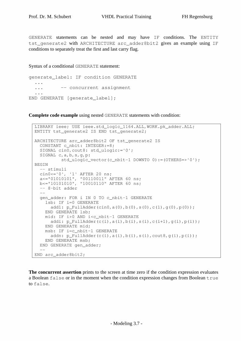
GENERATE statements can be nested and may have IF conditions. The ENTITY tst_generate2 with ARCHITECTURE arc_adder8bit2 gives an example using IF conditions to separately treat the first and last carry flag. Syntax of a conditional GENERATE statement: generate_label: IF condition GENERATE ... ... -- concurrent assignment ... END GENERATE [generate_label]; Complete code example using nested GENERATE statements with condition:
LIBRARY ieee; USE ieee.std_logic_1164.ALL,WORK.pk_adder.ALL; ENTITY tst_generate2 IS END tst_generate2; ARCHITECTURE arc_adder8bit2 OF tst_generate2 IS CONSTANT c_nbit: INTEGER:=8; SIGNAL cin0,cout8: std_ulogic:='0'; SIGNAL c,a,b,s,g,p: std_ulogic_vector(c_nbit-1 DOWNTO 0):=(OTHERS=>'0'); BEGIN -- stimuli cin0<='0', '1' AFTER 20 ns; a<="01010101", "00110011" AFTER 60 ns; b<="10101010", "10010110" AFTER 60 ns; -- 8-bit adder -- gen_adder: FOR i IN 0 TO c_nbit-1 GENERATE lsb: IF i=0 GENERATE add1: p_FullAdder(cin0,a(0),b(0),s(0),c(1),g(0),p(0)); END GENERATE lsb; mid: IF i>0 AND i<c_nbit-1 GENERATE addi: p_FullAdder(c(i),a(i),b(i),s(i),c(i+1),g(i),p(i)); END GENERATE mid; msb: IF i=c_nbit-1 GENERATE addn: p_FullAdder(c(i),a(i),b(i),s(i),cout8,g(i),p(i)); END GENERATE msb; END GENERATE gen_adder; -- END arc_adder8bit2;
The concurrent assertion prints to the screen at time zero if the condition expression evaluates a Boolean false or in the moment when the condition expression changes from Boolean true to false.

Prof. Dr. M. Schubert VHDL Practical Training FH Regensburg
- Modeling 3.8 -
3.2.5 BLOCK Statement
BNF:
block_statement ::= block label : BLOCK [ ( guard_expression ) ] [ IS ] block_header block_declarative_part BEGIN block_statement_part END BLOCK [ block_label ] ;
The BLOCK statement is used in the following way:
block_label: BLOCK [(guard_expression)] -- concurrent declarations BEGIN -- concurrent code END BLOCK [block_label];
A BLOCK is concurrent. BLOCKs allow for design partitioning and local signal declarations. External signals and constants are visible inside the block. BLOCK statements may have a guard expression. The guarded assignment
signal_g <= GUARDED wave_form; can be translated into the equivalent sequential code
IF guard_expression THEN signal_g <= wave_form; END IF;
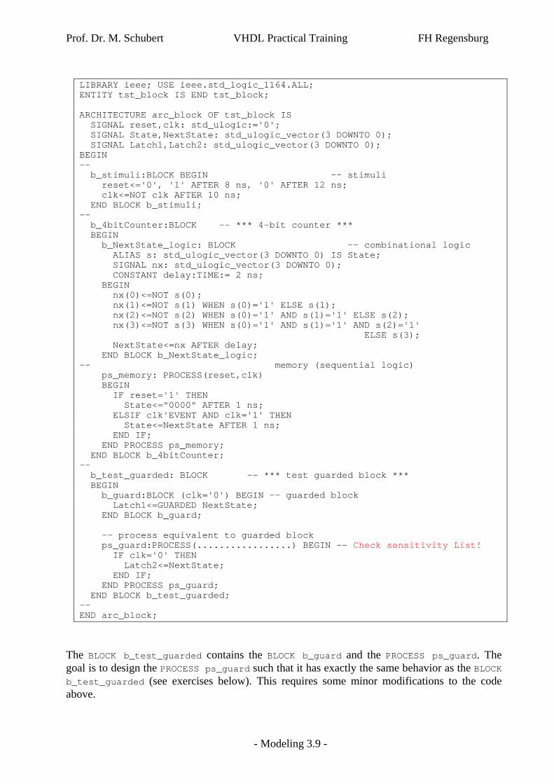
where guard_expression has to deliver a Boolean result. The following source code comprehends three exercises to demonstrate the capability of BLOCK statements. The BLOCK named b_stimuli delivers the stimuli for the next two blocks. The stimuli are declared outside of the all BLOCK statements, so they are visible inside and outside of them. The BLOCK named b_4bitCounter contains the model of a 4-bit synchronous counter consisting of two subblocks: one BLOCK and one PROCESS statement. The BLOCK named b_logic contains the combinational logic, the PROCESS labeled ps_memory models the memory.
Prof. Dr. M. Schubert VHDL Practical Training FH Regensburg
- Modeling 3.9 -
LIBRARY ieee; USE ieee.std_logic_1164.ALL; ENTITY tst_block IS END tst_block; ARCHITECTURE arc_block OF tst_block IS SIGNAL reset,clk: std_ulogic:='0'; SIGNAL State,NextState: std_ulogic_vector(3 DOWNTO 0); SIGNAL Latch1,Latch2: std_ulogic_vector(3 DOWNTO 0); BEGIN -- b_stimuli:BLOCK BEGIN -- stimuli reset<='0', '1' AFTER 8 ns, '0' AFTER 12 ns; clk<=NOT clk AFTER 10 ns; END BLOCK b_stimuli; -- b_4bitCounter:BLOCK -- *** 4-bit counter *** BEGIN b_NextState_logic: BLOCK -- combinational logic ALIAS s: std_ulogic_vector(3 DOWNTO 0) IS State; SIGNAL nx: std_ulogic_vector(3 DOWNTO 0); CONSTANT delay:TIME:= 2 ns; BEGIN nx(0)<=NOT s(0); nx(1)<=NOT s(1) WHEN s(0)='1' ELSE s(1); nx(2)<=NOT s(2) WHEN s(0)='1' AND s(1)='1' ELSE s(2); nx(3)<=NOT s(3) WHEN s(0)='1' AND s(1)='1' AND s(2)='1' ELSE s(3); NextState<=nx AFTER delay; END BLOCK b_NextState_logic; -- memory (sequential logic) ps_memory: PROCESS(reset,clk) BEGIN IF reset='1' THEN State<="0000" AFTER 1 ns; ELSIF clk'EVENT AND clk='1' THEN State<=NextState AFTER 1 ns; END IF; END PROCESS ps_memory; END BLOCK b_4bitCounter; -- b_test_guarded: BLOCK -- *** test guarded block *** BEGIN b_guard:BLOCK (clk='0') BEGIN -- guarded block Latch1<=GUARDED NextState; END BLOCK b_guard; -- process equivalent to guarded block ps_guard:PROCESS(.................) BEGIN –- Check sensitivity List! IF clk='0' THEN Latch2<=NextState; END IF; END PROCESS ps_guard; END BLOCK b_test_guarded; -- END arc_block;
The BLOCK b_test_guarded contains the BLOCK b_guard and the PROCESS ps_guard. The goal is to design the PROCESS ps_guard such that it has exactly the same behavior as the BLOCK b_test_guarded (see exercises below). This requires some minor modifications to the code above.
Prof. Dr. M. Schubert VHDL Practical Training FH Regensburg
- Modeling 3.10 -
Exercise 3.2.5-1: We will now investigate the BLOCK labeled b_4bitCounter. a) Run ENTITY tst_block with the ARCHITECTURE arc_block until 400 ns. Does the
state vector represented by the signal State work correctly as a 4-bit counter? b) Which three declarations are made in the declaration region of BLOCK b_logic? c) Are this three local declarations visible outside of BLOCK b_logic? d) The delay of the NextState vector evaluated in response to a change of the State
vector increases from 2 ns to 12 ns at time point 50 ns. Has this change in delay impact on the assignment intervals of the State vector? Give reasons: Why or why not?
e) Important for the next exercise: What is the value of clk when the signal change of NextState occurs below simulation time = 50 ns?
f) Important for the next exercise: What is the value of clk when the signal change of NextState occurs above simulation time = 50 ns?
Exercise 3.2.5-2: We will now investigate the BLOCK labeled b_test_guarded. a) Observe the assignment of NextState to the signal Latch1 in the guarded BLOCK named b_guard. What is the boolean condition to enable for the assignment of Latch1?
b) Does this guarded assignment correspond to a state controlled latch or to an edge triggered FilpFlop?
c) The BLOCK labeled b_guard is followed by a PROCESS labeled ps_guard. Change the sensitivity list of this process such, that the signals Latch1 and Latch2 behave identical with a minimum number of signals in the sensitivity list. (The actual signal reset in the sensitivity list is just a dummy.)
Blocks can be useful to synthesize TriState buffers. For more detailed information about this topic the reader is referred to the literature.
Prof. Dr. M. Schubert VHDL Practical Training FH Regensburg
- Modeling 3.11 -
3.3 Sequential Modeling
3.3.1 Sequential Statements
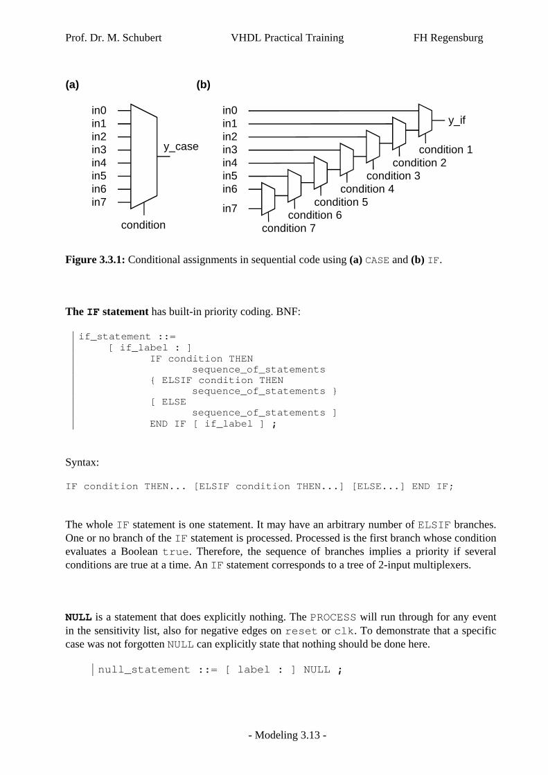
VHDL code is sequential within PROCESSes and subprograms. Subprograms are FUNCTIONs and PROCEDUREs. Sequential code is processed top down line by line. Six sequential statements are available: ASSERT LOOP CASE NULL IF WAIT The sequential assertion prints to the screen if the program pointer processes the ASSERT statement and the condition expression evaluates a Boolean false. The CASE statement is similar to the IF statement on the first glance. However, it is easier to synthesize, because the IF statement has a new condition in any ELSIF branch, while the CASE statement takes all decisions on the base of one condition. It corresponds to a multiplexer with inputs of equivalent importance. BNF:
case_statement ::= [ case_label : ] CASE expression IS case_statement_alternative { case_statement_alternative } END CASE [ case_label ] ;
Syntax: l_label: CASE expression IS WHEN choices => sequential_code [WHEN choices => sequential_code] [WHEN OTHERS => sequential_code] END CASE l_label; After the WHEN keyword there may be several choices separated by a vertical bar, which symbolizes a logical OR. Example: WHEN choice1|choice2|choic3|choice4 => sequential_code Because all possible choices must be covered, the OTHERS keyword is helpful.

Prof. Dr. M. Schubert VHDL Practical Training FH Regensburg
- Modeling 3.12 -
Exercise: a) Compile, load and run the ENTITY tst_case for 150 ns. b) Are the operations AND, OR, XOR, ADD processed correctly? c) Observe the signal y at time point 30 ns. Why do all bits change to '0'? Complete code example of a little ALU:
LIBRARY ieee; USE ieee.std_logic_1164.ALL,ieee.std_logic_unsigned."+"; ENTITY tst_case IS END tst_case; ARCHITECTURE arc_case OF tst_case IS TYPE t_instruction IS(inst_and,inst_or,inst_xor,inst_add); SIGNAL instruction: t_instruction; SIGNAL cin,cout: std_ulogic:='0'; SIGNAL a,b,y: std_ulogic_vector(7 DOWNTO 0):=(OTHERS=>'0'); BEGIN -- stimuli cin<='0', '1' AFTER 30 ns; a<="01010101", "00110011" AFTER 60 ns; b<="10101010", "10010110" AFTER 60 ns; instruction<=inst_and, inst_or AFTER 60 ns, inst_xor AFTER 90 ns, inst_add AFTER 120 ns; -- ALU ps_alu: PROCESS(a,b,cin,instruction) BEGIN CASE instruction IS WHEN inst_and => y<=a AND b; WHEN inst_or => y<=a OR b; WHEN inst_xor => y<=a XOR b; WHEN inst_add => y<=a + b; WHEN OTHERS => ASSERT false REPORT "unknown instruction" SEVERITY ERROR; END CASE; END PROCESS ps_alu; END arc_case;
Prof. Dr. M. Schubert VHDL Practical Training FH Regensburg
- Modeling 3.13 -
condition
in0in1in2in3in4in5in6in7
(a)
condition 1
in0in1in2in3in4in5in6
in7
(b)
condition 2condition 3
condition 4condition 5
condition 6condition 7
y_if
y_case
Figure 3.3.1: Conditional assignments in sequential code using (a) CASE and (b) IF. The IF statement has built-in priority coding. BNF:
if_statement ::= [ if_label : ] IF condition THEN sequence_of_statements { ELSIF condition THEN sequence_of_statements } [ ELSE sequence_of_statements ] END IF [ if_label ] ;
Syntax: IF condition THEN... [ELSIF condition THEN...] [ELSE...] END IF; The whole IF statement is one statement. It may have an arbitrary number of ELSIF branches. One or no branch of the IF statement is processed. Processed is the first branch whose condition evaluates a Boolean true. Therefore, the sequence of branches implies a priority if several conditions are true at a time. An IF statement corresponds to a tree of 2-input multiplexers. NULL is a statement that does explicitly nothing. The PROCESS will run through for any event in the sensitivity list, also for negative edges on reset or clk. To demonstrate that a specific case was not forgotten NULL can explicitly state that nothing should be done here.
null_statement ::= [ label : ] NULL ;

Prof. Dr. M. Schubert VHDL Practical Training FH Regensburg
- Modeling 3.14 -
Complete code example for IF and NULL:
ENTITY tst_if_null IS END tst_if_null; ARCHITECTURE arc_toggle_flipflop OF tst_if_null IS SIGNAL reset,clk,q,d: BIT; BEGIN -- stimuli reset<='0', '1' AFTER 50 ns, '0' AFTER 70 ns; clk<=NOT clk AFTER 20 ns; d<=NOT q AFTER 2 ns; -- d-FlipFlop ps_dff: PROCESS(reset,clk) BEGIN IF clk'EVENT AND clk='1' THEN q<=d AFTER 2 ns; ELSIF reset='0' THEN q<='0' AFTER 2 ns; ELSE NULL; END IF; END PROCESS ps_dff; END arc_toggle_flipflop;
d
clk
q
reset
dff
Toggle Flip-Flop (TFF) Exercise: a) Compile, load and run the ENTITY tst_if_null for 100 ns. b) Observe specifically the time 60-64 ns: Can the FlipFlop be set during reset='1'? c) Explain the behavior of signal q observed between 60-64 ns. d) What must be done to give the highest priority to the reset signal? Try it! Loops are possible in sequential code. BNF:
loop_statement ::= [ loop_label : ] [ iteration_scheme ] LOOP sequence_of_statements END LOOP [ loop_label ] ;
Syntax: [loop_label:] [iteration_scheme] LOOP… END LOOP [loop_label];
Prof. Dr. M. Schubert VHDL Practical Training FH Regensburg
- Modeling 3.15 -
The easiest way to produce an endless loop is the statement LOOP END LOOP; If a loop label is used before the LOOP keyword, it must e repeated after END LOOP. There are two possible iteration schemes: (1) FOR index IN discrete_range and (2) WHILE condition. Examples: FOR i IN 0 TO 15 LOOP ... FOR i IN 7 DOWNTO 0 LOOP ... FOR i IN DataBus'RANGE LOOP ... WHILE I>=0 AND i<c_DataBusWidth LOOP ... The range index of the FOR loop is implicitly declared by the LOOP statement and must not be assigned or modified inside the loop. A data object with same name as the loop index (e.g. a signal named i) is masked by the loop index and is not visible inside the loop. LOOP statements can be nested. In this case the inner loop must be completely inside the outer loop. There are two more statements available inside a LOOP: NEXT; EXIT [loop_label] [WHEN condition]; NEXT causes a jump to the next END LOOP without exiting the loop. EXIT causes the program to halt and to resume execution after the next END LOOP. The phrase EXIT loop_label causes the program to continue execution after END LOOP loop_label. An EXIT statement with condition is only executed when the condition evaluates Boolean true. The PROCESS statement can have either a sensitivity list or WAIT statements. There are four possible WAIT statements: WAIT; -- waits forever WAIT FOR time; -- waits for a given amount of time; WAIT ON signal [,signal]; -- waits for events on sensit. list WAIT UNTIL condition; -- waits until a condition is true
Prof. Dr. M. Schubert VHDL Practical Training FH Regensburg
- Modeling 3.16 -
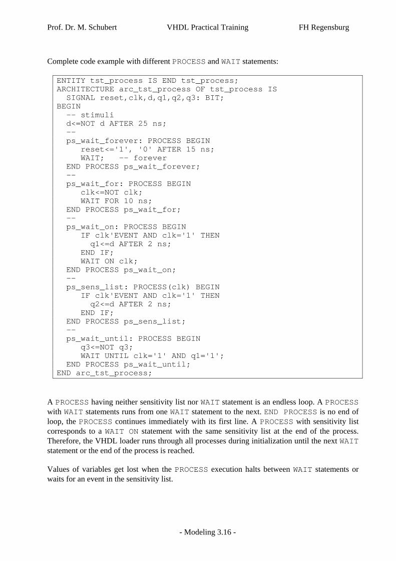
Complete code example with different PROCESS and WAIT statements: ENTITY tst_process IS END tst_process; ARCHITECTURE arc_tst_process OF tst_process IS SIGNAL reset,clk,d,q1,q2,q3: BIT; BEGIN -- stimuli d<=NOT d AFTER 25 ns; -- ps_wait_forever: PROCESS BEGIN reset<='1', '0' AFTER 15 ns; WAIT; -- forever END PROCESS ps_wait_forever; -- ps_wait_for: PROCESS BEGIN clk<=NOT clk; WAIT FOR 10 ns; END PROCESS ps_wait_for; -- ps_wait_on: PROCESS BEGIN IF clk'EVENT AND clk='1' THEN q1<=d AFTER 2 ns; END IF; WAIT ON clk; END PROCESS ps_wait_on; -- ps_sens_list: PROCESS(clk) BEGIN IF clk'EVENT AND clk='1' THEN q2<=d AFTER 2 ns; END IF; END PROCESS ps_sens_list; -- ps_wait_until: PROCESS BEGIN q3<=NOT q3; WAIT UNTIL clk='1' AND q1='1'; END PROCESS ps_wait_until; END arc_tst_process;
A PROCESS having neither sensitivity list nor WAIT statement is an endless loop. A PROCESS with WAIT statements runs from one WAIT statement to the next. END PROCESS is no end of loop, the PROCESS continues immediately with its first line. A PROCESS with sensitivity list corresponds to a WAIT ON statement with the same sensitivity list at the end of the process. Therefore, the VHDL loader runs through all processes during initialization until the next WAIT statement or the end of the process is reached. Values of variables get lost when the PROCESS execution halts between WAIT statements or waits for an event in the sensitivity list.

Prof. Dr. M. Schubert VHDL Practical Training FH Regensburg
- Modeling 3.17 -
Exercise: a) Compile, load and run the ENTITY tst_process for 100 ns. b) Which two processes in the code above must work per definition identical? c) Which two signals in the code example above must therefore behave identical? d) Can we rely on that a variable does not change its value when the PROCESS executes a WAIT
statement?

Prof. Dr. M. Schubert VHDL Practical Training FH Regensburg
- Modeling 3.18 -
3.3.2 Signal Assignment in Sequential Environment
A piece of sequential code delivers a maximum of one driver per signal. This is different from concurrent code, where multiply driven signals require a resolution function, because all drivers are assumed to drive simultaneously. In the following example we have: 1. a waveform assignment for signal s0, 2. multiple inertial assignments to signal s1, 3. three inertial assignments to signal s2, 4. multiple transport assignments to signal s3.
ENTITY seq_sig_assign IS END seq_sig_assign; ARCHITECTURE arc_seq_sig_assign OF seq_sig_assign IS SIGNAL s0,s1,s2,s3: INTEGER:=0; BEGIN PROCESS BEGIN s0<=10 AFTER 10 ns, 20 AFTER 20 ns, 30 AFTER 30 ns, 40 AFTER 40 ns, 50 AFTER 50 ns; -- waveform -- assignment -- s1<=10 AFTER 10 ns; s1<=20 AFTER 20 ns; s1<=30 AFTER 30 ns; s1<=40 AFTER 40 ns; s1<=40 AFTER 50 ns; s1<=10 AFTER 35 ns; -- s2<=10 AFTER 10 ns; s2<=20 AFTER 20 ns; s2<=20 AFTER 30 ns; -- s3<=TRANSPORT 10 AFTER 10 ns; s3<=TRANSPORT 20 AFTER 20 ns; s3<=TRANSPORT 30 AFTER 30 ns; s3<=TRANSPORT 40 AFTER 40 ns; s3<=TRANSPORT 50 AFTER 50 ns; s3<=TRANSPORT 10 AFTER 35 ns; WAIT; -- forever END PROCESS; END arc_seq_sig_assign;
Rule 1: Inertial signal assignment allows to schedule a maximum of 1 event. The latest assignment in sequential code cancels all other assignments. Rule 2: In exception to rule 1, an inertial scheduling in sequential code is ignored, if the scheduled value was already scheduled for an earlier time point. Rule 3: Transport signal assignment for time point t3 cancels all scheduling for times txt3 and replaces it with the new scheduling.

Prof. Dr. M. Schubert VHDL Practical Training FH Regensburg
- Modeling 3.19 -
Exercise 3.2-5: a) Signal s1 is scheduled several times in the code example above. Express the behavior of
signal s1 using a waveform assignment like for signal s0. Explain the result. b) Express the behavior of signal s2 using a waveform assignment like for signal s0. Explain
the result. c) Express the behavior of signal s3 using a waveform assignment like for signal s0. Explain
the result. d) Compile, load and run the driv_seq_inertial for 100 ns to check your estimations.
Prof. Dr. M. Schubert VHDL Practical Training FH Regensburg
- Modeling 3.20 -
3.4 Subprograms
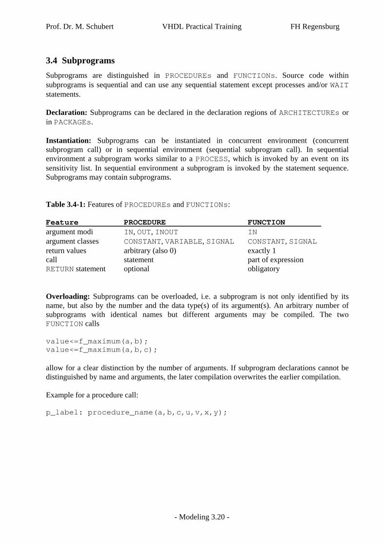
Subprograms are distinguished in PROCEDUREs and FUNCTIONs. Source code within subprograms is sequential and can use any sequential statement except processes and/or WAIT statements. Declaration: Subprograms can be declared in the declaration regions of ARCHITECTUREs or in PACKAGEs. Instantiation: Subprograms can be instantiated in concurrent environment (concurrent subprogram call) or in sequential environment (sequential subprogram call). In sequential environment a subprogram works similar to a PROCESS, which is invoked by an event on its sensitivity list. In sequential environment a subprogram is invoked by the statement sequence. Subprograms may contain subprograms. Table 3.4-1: Features of PROCEDUREs and FUNCTIONs: Feature PROCEDURE FUNCTION argument modi IN, OUT, INOUT IN argument classes CONSTANT, VARIABLE, SIGNAL CONSTANT, SIGNAL return values arbitrary (also 0) exactly 1 call statement part of expression RETURN statement optional obligatory Overloading: Subprograms can be overloaded, i.e. a subprogram is not only identified by its name, but also by the number and the data type(s) of its argument(s). An arbitrary number of subprograms with identical names but different arguments may be compiled. The two FUNCTION calls value<=f_maximum(a,b); value<=f_maximum(a,b,c); allow for a clear distinction by the number of arguments. If subprogram declarations cannot be distinguished by name and arguments, the later compilation overwrites the earlier compilation. Example for a procedure call: p_label: procedure_name(a,b,c,u,v,x,y);
Prof. Dr. M. Schubert VHDL Practical Training FH Regensburg
- Modeling 3.21 -
3.4.1 PROCEDUREs
3.4.1.1 PROCEDURE declaration
The PROCEDURE statement as used in the declaration region of an ARCHITECTURE or a PACKAGE BODY is Package: PROCEDURE procedure_name(...); Package Body or architecture declaration region: PROCEDURE procedure_name(...) IS BEGIN -- executable VHDL code END procedure_name; For a package user the subprogram is visible only if it is mentioned in the package header. Otherwise it can be used only in the package body below its declaration. BNF:
subprogram_specification ::= PROCEDURE designator [ ( formal_parameter_list ) ] | [ PURE | IMPURE ] FUNCTION designator [ ( formal_parameter_list ) ] RETURN type_mark
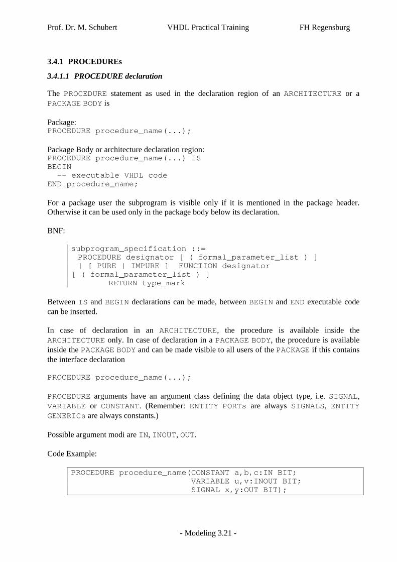
Between IS and BEGIN declarations can be made, between BEGIN and END executable code can be inserted. In case of declaration in an ARCHITECTURE, the procedure is available inside the ARCHITECTURE only. In case of declaration in a PACKAGE BODY, the procedure is available inside the PACKAGE BODY and can be made visible to all users of the PACKAGE if this contains the interface declaration PROCEDURE procedure_name(...); PROCEDURE arguments have an argument class defining the data object type, i.e. SIGNAL, VARIABLE or CONSTANT. (Remember: ENTITY PORTs are always SIGNALS, ENTITY GENERICs are always constants.) Possible argument modi are IN, INOUT, OUT. Code Example:
PROCEDURE procedure_name(CONSTANT a,b,c:IN BIT; VARIABLE u,v:INOUT BIT; SIGNAL x,y:OUT BIT);

Prof. Dr. M. Schubert VHDL Practical Training FH Regensburg
- Modeling 3.22 -
Arguments of mode IN may have the classes CONSTANT, which is default, and SIGNAL and both cannot be assigned inside the subprogram due to mode IN. A SIGNAL has attributes while a CONSTANT has not. Arguments of mode OUT and INOUT may have the classes SIGNAL, VARIABLE and CONSTANT. Arguments of mode IN may be given default values by appending ":=default_value" to the respective argument declaration. 3.4.1.2 PROCEDURE instantiation
Example for a procedure call: p_label: procedure_name(a,b,c,u,v,x,y); 3.4.2 FUNCTIONs
3.4.2.1 FUNCTION declaration
The FUNCTION statement as used in the declaration region of an ARCHITECTURE or a PACKAGE BODY is Package Body: FUNCTION function_name(...) RETURN data_type IS VARIABLE … CONSTANT … SIGNAL … ALIAS … BEGIN … RETURN <data_type> END function_name; Between IS and BEGIN declarations can be made, between BEGIN and END executable code can be inserted. In case of declaration in an ARCHITECTURE, the function is available inside the ARCHITECTURE only. In case of declaration in a PACKAGE BODY, the function is available inside the PACKAGE BODY and can be made visible to all users of the PACKAGE if this contains the interface declaration FUNCTION function_name(...) RETURN data_type; As the only possible argument modus is IN the keyword IN may be omitted.
Prof. Dr. M. Schubert VHDL Practical Training FH Regensburg
- Modeling 3.23 -
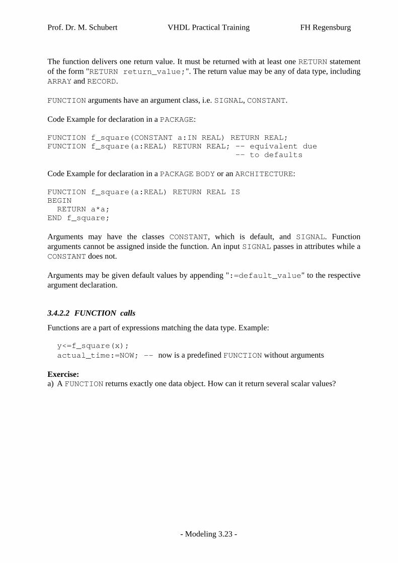
The function delivers one return value. It must be returned with at least one RETURN statement of the form "RETURN return_value;". The return value may be any of data type, including ARRAY and RECORD. FUNCTION arguments have an argument class, i.e. SIGNAL, CONSTANT. Code Example for declaration in a PACKAGE: FUNCTION f_square(CONSTANT a:IN REAL) RETURN REAL; FUNCTION f_square(a:REAL) RETURN REAL; -- equivalent due -- to defaults Code Example for declaration in a PACKAGE BODY or an ARCHITECTURE: FUNCTION f_square(a:REAL) RETURN REAL IS BEGIN RETURN a*a; END f_square; Arguments may have the classes CONSTANT, which is default, and SIGNAL. Function arguments cannot be assigned inside the function. An input SIGNAL passes in attributes while a CONSTANT does not. Arguments may be given default values by appending ":=default_value" to the respective argument declaration. 3.4.2.2 FUNCTION calls
Functions are a part of expressions matching the data type. Example: y<=f_square(x); actual_time:=NOW; -- now is a predefined FUNCTION without arguments Exercise: a) A FUNCTION returns exactly one data object. How can it return several scalar values?

Prof. Dr. M. Schubert VHDL Practical Training FH Regensburg
- Modeling 3.24 -
3.5 Some Advanced Topics
3.5.1 Design Styles
We distinguish three design styles: closed: no more decision can be made generic: a certain degree of freedom is left to adapt the design to specific applications configurable: the user can change the design in a very wide range. Closed style would be for example:
TYPE t_DataBus IS std_ulogic_vector(15 DOWNTO 0); Latch<=DataBus AFTER 10 ns; Generic style would be in this example:
CONSTANT c_BusWidth:INTEGER:=16; CONSTANT c_BufferDelay:TIME:=10 ns; .. TYPE t_DataBus IS std_ulogic_vector(c_BusWidth-1 DOWNTO 0); Latch<=DataBus AFTER c_BufferDelay; This type of writing code is not only generic but also more readable. It contains the information c_BusWidth-1 instead of 15. Furthermore, it is better suited for reusability, as the width of the bus is easily adapted with the constant c_BusWidth and all delays are easily adapted to an other technology with the constant c_BufferDelay. This is the coding style that should be preferred. Configurable would be e.g. a digital filter of variable length with all coefficients adjustable. This is nice but expensive to test. 3.5.2 Modeling Styles
Typically we find three kinds of VHDL code: Modeling Style Feature Applications behavioral non synthesizable testbenches, top-level, ext. devices (drives, etc.) RTL1) synthesizable typically the code under development gate level primitives after synthesis, backannotation, timing 1)RTL = Register Transfer Level