vhdl and verilog for modeling module10 rev husers.wpi.edu/~rjduck/vhdl and verilog for...
TRANSCRIPT

Jim Duckworth, WPI VHDL and Verilog for Modeling - Module 101
VHDL and Verilog for Modeling
Module 10

Jim Duckworth, WPI VHDL and Verilog for Modeling - Module 102
Overview
• General examples
– AND model
– Flip-flop model
– SRAM Model
• Customizing Models
– Generics in VHDL
• DDR SDRAM Model
– Parameters in Verilog
• Using Files in Verilog for Test Benches

Jim Duckworth, WPI VHDL and Verilog for Modeling - Module 103
VHDL for Modeling
• We have covered
– VHDL for Synthesis
– VHDL for testing (simulation)
• Now - VHDL for modeling
• Describes the expected behavior of a component or device
• Can be used to test other components
– for example a model of a CPU could be used to test:
• UART
• DRAM memory controller
• cache controller

Jim Duckworth, WPI VHDL and Verilog for Modeling - Module 104
AND gate model
-- 74LS08 model (typical delays)
ENTITY ls08 IS
PORT(a, b : IN std_logic;
c : OUT std_logic);
END ls08;
ARCHITECTURE behav OF ls08 IS
BEGIN
c <= ‘1’ AFTER 8 ns WHEN a = ‘1’ AND b = ‘1’ ELSE
‘0’ AFTER 10 ns;
END behav;

Jim Duckworth, WPI VHDL and Verilog for Modeling - Module 105
Simulation Results

Jim Duckworth, WPI VHDL and Verilog for Modeling - Module 106
D flip-flop model
-- 74LS74 model (typical delays)
ENTITY ls74 IS
PORT(d, clr, pre, clk : IN std_logic;
q : OUT std_logic);
END ls74;
ARCHITECTURE behav OF ls74 IS
BEGIN
PROCESS(clk, clr, pre)
BEGIN
IF clr = ‘0’ THEN
q <= ‘0’ AFTER 25 ns;
ELSIF pre = ‘0’ THEN
q <= ‘1’ AFTER 13 ns;
ELSIF clk’EVENT AND clk = ‘1’ THEN
IF d = ‘1’ THEN
q <= ‘1’ AFTER 13 ns;
ELSE
q <= ‘0’ AFTER 25 ns;
END IF;
END IF;
END PROCESS;
END behav;

Jim Duckworth, WPI VHDL and Verilog for Modeling - Module 107
Simulation Results

Jim Duckworth, WPI VHDL and Verilog for Modeling - Module 108
Adding Constants - same as previous
-- 74LS74 model (typical delays)
ENTITY ls74 IS
PORT(d, clr, pre, clk : IN std_logic;
q : OUT std_logic);
CONSTANT t_rise : TIME := 13 ns;
CONSTANT t_fall : TIME := 25 ns;
END ls74;
ARCHITECTURE behav OF ls74 IS
BEGIN
PROCESS(clk, clr, pre)
BEGIN
IF clr = ‘0’ THEN
q <= ‘0’ AFTER t_fall;
ELSIF pre = ‘0’ THEN
q <= ‘1’ AFTER t_rise;
ELSIF clk’EVENT AND clk = ‘1’ THEN
IF d = ‘1 THEN
q <= ‘1’ AFTER t_rise;
ELSE
q <= ‘0’ AFTER t_fall;
END IF;
END IF;
END PROCESS;
END behav;

Jim Duckworth, WPI VHDL and Verilog for Modeling - Module 109
Adding setup and pulse width checks
LIBRARY ieee;
USE ieee.std_logic_1164.ALL;
ENTITY ls74 IS
PORT(d, clr, pre, clk : IN std_logic;
q : OUT std_logic);
CONSTANT t_rise : TIME := 13 ns;
CONSTANT t_fall : TIME := 25 ns;
CONSTANT t_setup : TIME := 20 ns;
CONSTANT t_width : TIME := 25 ns;
END ls74;

Jim Duckworth, WPI VHDL and Verilog for Modeling - Module 1010
Basic D flip-flop description same
ARCHITECTURE behav OF ls74 IS
BEGIN
PROCESS(clk, clr, pre)
BEGIN
IF clr = '0' THEN
q <= '0' AFTER t_fall;
ELSIF pre = '0' THEN
q <= '1' AFTER t_rise;
ELSIF clk'EVENT AND clk = '1' THEN
IF d = '1' THEN
q <= '1' AFTER t_rise;
ELSE
q <= '0' AFTER t_fall;
END IF;
END IF;
END PROCESS;

Jim Duckworth, WPI VHDL and Verilog for Modeling - Module 1011
Add setup and pulse width checks
-- process to check data setup time
PROCESS(clk)
BEGIN
IF clk'EVENT AND clk = '1' THEN
ASSERT d'LAST_EVENT > t_setup
REPORT "D changed within setup time"
SEVERITY ERROR;
END IF;
END PROCESS;
-- process to check clock high pulse width
PROCESS(clk)
VARIABLE last_clk : TIME := 0 ns;
BEGIN
IF clk'EVENT AND clk = '0' THEN
ASSERT NOW - last_clk > t_width
REPORT "Clock pulse width too short"
SEVERITY ERROR;
ELSE
last_clk := NOW;
END IF;
END PROCESS;
END behav;

Jim Duckworth, WPI VHDL and Verilog for Modeling - Module 1012
Complete LS74 Model

Jim Duckworth, WPI VHDL and Verilog for Modeling - Module 1013
Test Bench – without SRAM
• SRAM connections are open
DSP
Picoblaze
Display
ZZ

Jim Duckworth, WPI VHDL and Verilog for Modeling - Module 1014
SRAM model – simplified, no delays
Jim Duckworth, WPI VHDL and Verilog for Modeling - Module 1015
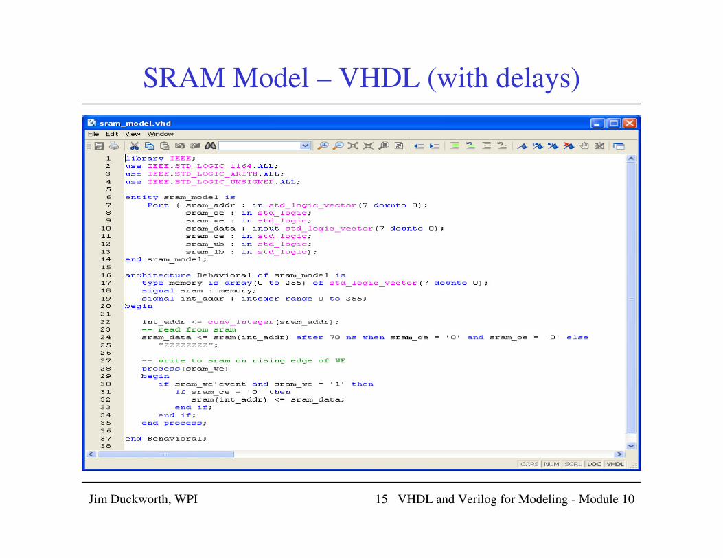
SRAM Model – VHDL (with delays)

Jim Duckworth, WPI VHDL and Verilog for Modeling - Module 1016
SRAM Model Read and Write

Jim Duckworth, WPI VHDL and Verilog for Modeling - Module 1017
Adding the SRAM model
• New testbench
SRAM
Model
DSP
Picoblaze
Display

Jim Duckworth, WPI VHDL and Verilog for Modeling - Module 1018
Adding the SRAM model to the test bench

Jim Duckworth, WPI VHDL and Verilog for Modeling - Module 1019
Generics
• Generics useful for making design units more general
purpose
• Generics allow information to be passed into a design
description
• Example information
– propagation delays
– size of component (changing input and output ports)

Jim Duckworth, WPI VHDL and Verilog for Modeling - Module 1020
LS08 example with generics
-- 74LS08 model
ENTITY ls08 IS
GENERIC(t_rise, t_fall : TIME);
PORT(a, b : IN std_logic;
c : OUT std_logic);
END ls08;
ARCHITECTURE behav OF ls08 IS
BEGIN
c <= ‘1’ AFTER t_rise WHEN a = ‘1’ AND b = ‘1’ ELSE
‘0’ AFTER t_fall;
END behav;
• This is now a parameterized model (general purpose)
rather than hard-coded version
• Actual delay is determined at simulation time (or
synthesis) by value passed to model

Jim Duckworth, WPI VHDL and Verilog for Modeling - Module 1021
Instantiating Components with Generics
-- example use of LS08 with generic values
ENTITY test IS
PORT(in1, in2, in3 : IN std_logic;
out1 : OUT std_logic);
END test;
ARCHITECTURE behav OF test IS
COMPONENT ls08
GENERIC(t_rise, t_fall : TIME);
PORT(a, b : IN std_logic;
c : OUT std_logic);
END COMPONENT;
SIGNAL int : std_logic;
BEGIN
u1: ls08 GENERIC MAP(8 ns, 10 ns) -- typical delays
PORT MAP(a => in1, b => in2, c => int);
u2: ls08 GENERIC MAP(15 ns, 20 ns) -- max delays
PORT MAP(a => int, b => in3, c => out1);
END behav;

Jim Duckworth, WPI VHDL and Verilog for Modeling - Module 1022
Another Example (with default values)
• Can provide default values for generics
• Only need GENERIC MAP if necessary to change them
ENTITY and2 IS
GENERIC(t_rise, t_fall : TIME := 10 ns;
load : INTEGER := 3);
PORT(a, b IN : IN std_logic;
c : OUT std_logic);
END and2;
ARCHITECTURE generic_model OF and2 IS
BEGIN
c <= ‘1’ AFTER (t_rise + (load * 2 ns)) WHEN a = ‘1’ AND b = ‘1’ ELSE
‘0’ AFTER (t_fall + (load * 2 ns));
END generic_model;
u1: and2 GENERIC MAP(5 ns, 7 ns, 4) PORT MAP (a = > ……); -- default overridden
u2: and2 PORT MAP(a => ……); -- uses default values

Jim Duckworth, WPI VHDL and Verilog for Modeling - Module 1023
Modifying Component Size (also for synthesis)

Jim Duckworth, WPI VHDL and Verilog for Modeling - Module 1024
Making two copies – different size

Jim Duckworth, WPI VHDL and Verilog for Modeling - Module 1025
Schematic of two shift registers

Jim Duckworth, WPI VHDL and Verilog for Modeling - Module 1026
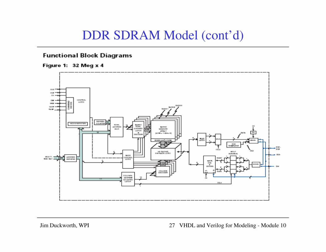
DDR SDRAM Model
Jim Duckworth, WPI VHDL and Verilog for Modeling - Module 1027
DDR SDRAM Model (cont’d)

Jim Duckworth, WPI VHDL and Verilog for Modeling - Module 1028
DDR SDRAM Model (cont’d)

Jim Duckworth, WPI VHDL and Verilog for Modeling - Module 1029
DDR SDRAM Model (cont’d)

Jim Duckworth, WPI VHDL and Verilog for Modeling - Module 1030

Jim Duckworth, WPI VHDL and Verilog for Modeling - Module 1031
Verilog Lower Level Module with Parameters
Jim Duckworth, WPI 31

Jim Duckworth, WPI VHDL and Verilog for Modeling - Module 1032Jim Duckworth, WPI 32

Jim Duckworth, WPI VHDL and Verilog for Modeling - Module 1033
Three copies of XYZ module
Jim Duckworth, WPI 33

Jim Duckworth, WPI VHDL and Verilog for Modeling - Module 1034
RTL Schematic showing 3 modules
Jim Duckworth, WPI VHDL for Modeling - Module 1034

Jim Duckworth, WPI VHDL and Verilog for Modeling - Module 1035
(Misc) Using UCF to specify pin options
Jim Duckworth, WPI 35

Jim Duckworth, WPI VHDL and Verilog for Modeling - Module 1036Jim Duckworth, WPI 36

Jim Duckworth, WPI VHDL and Verilog for Modeling - Module 1037Jim Duckworth, WPI 37

Jim Duckworth, WPI VHDL and Verilog for Modeling - Module 1038
Timing Check Tasks in Verilog
• Specify block can be used to specify setup and hold times for signals
– specify and endspecify (Use specparam to define parameters in specify
block)
• $setup (data, clock edge, limit)
– Displays warning message if setup timing constraint is not met
– $setup(d, posedge clk, 10)
• $hold (clock edge, data, limit)
– Displays warning message if hold timing constraint is not met
– $setup(d, posedge clk, 2)
• $width (pulse event, limit)
– Displays warning message if pulse width is shorter than limit
– $setup(d, posedge clk, 20) – specify start edge of pulse
• $period (pulse event, limit)
– Check period of signal is sufficiently long
– $period(d, posedge clk, 50)
Jim Duckworth, WPI VHDL for Modeling - Module 1038

Jim Duckworth, WPI VHDL and Verilog for Modeling - Module 1039
Original Simple SRAM model
Jim Duckworth, WPI VHDL for Modeling - Module 1039

Jim Duckworth, WPI VHDL and Verilog for Modeling - Module 1040
Adding Timing Checks and Delay
Jim Duckworth, WPI VHDL for Modeling - Module 1040

Jim Duckworth, WPI VHDL and Verilog for Modeling - Module 1041
Testing with Test Bench
Jim Duckworth, WPI VHDL for Modeling - Module 1041

Jim Duckworth, WPI VHDL and Verilog for Modeling - Module 1042
Warning Messages
Jim Duckworth, WPI VHDL for Modeling - Module 1042

Jim Duckworth, WPI VHDL and Verilog for Modeling - Module 1043
ISSI SRAM – Verilog Model (partial)
• // IS61LV25616 Asynchronous SRAM, 256K x 16 = 4M; speed: 10ns.
• // Note; 1) Please include "+define+ OEb" in running script if you want to check
• // timing in the case of OE_ being set.
• // 2) Please specify access time by defining tAC_10 or tAC_12.
• // `define OEb
• `define tAC_10
• `timescale 1ns/10ps
• module IS61LV25616 (A, IO, CE_, OE_, WE_, LB_, UB_);
• parameter dqbits = 16;
• parameter memdepth = 262143;
• parameter addbits = 18;
• parameter Toha = 2;
• parameter Tsa = 2;
• `ifdef tAC_10
• parameter Taa = 10,
• Thzce = 3,
• Thzwe = 5;
• `endif
• `ifdef tAC_12
• parameter Taa = 12,
• Thzce = 5,
• Thzwe = 6;
• `endif
• input CE_, OE_, WE_, LB_, UB_;
• input [(addbits - 1) : 0] A;
• inout [(dqbits - 1) : 0] IO;
•
• wire [(dqbits - 1) : 0] dout;
• reg [(dqbits/2 - 1) : 0] bank0 [0 : memdepth];

Jim Duckworth, WPI VHDL and Verilog for Modeling - Module 1044
Micron SRAM on Nexys2
board
Complete model is > 1300 lines!

Jim Duckworth, WPI VHDL and Verilog for Modeling - Module 1045

Jim Duckworth, WPI VHDL and Verilog for Modeling - Module 1046

Jim Duckworth, WPI VHDL and Verilog for Modeling - Module 1047

Jim Duckworth, WPI VHDL and Verilog for Modeling - Module 1048
Additional Verilog System Tasks
• @ (posedge clk) – event control, wait for rising edge of clk
• wait (state == ENTER && ready == 1’b1) – wait for
specific condition
• #123 – wait for 123 timescale units
• $display (print out information)
• $monitor (displays information when signal changes value)
• $time and $realtime
• $fopen and $fclose
• Integer log_file = $fopen(“my_log”)
• $readmemb and $readmemh

Jim Duckworth, WPI VHDL and Verilog for Modeling - Module 1049
Decoder Test Bench in Verilog with Files

Jim Duckworth, WPI VHDL and Verilog for Modeling - Module 1050
Opening file in Verilog

Jim Duckworth, WPI VHDL and Verilog for Modeling - Module 1051

Jim Duckworth, WPI VHDL and Verilog for Modeling - Module 1052
Waveform Generated

Jim Duckworth, WPI VHDL and Verilog for Modeling - Module 1053
Console (and results file)