3-g construction approach and...
TRANSCRIPT

FINALENVIRONMENTALIMPACT STATEMENT
BrightwaterRegional WastewaterTreatment System
APPENDICES
3-GCONSTRUCTION APPROACH
AND SCHEDULE

Final
Appendix 3-GConstruction Approach and Schedule
August 2003
Prepared for King County byURS Construction ServicesSeattle, WA
For more information:Brightwater Project201 South Jackson Street, Suite 503Seattle, WA 98104-3855206-684-6799 or toll free 1-888-707-8571
Alternative formats available upon requestby calling 206-684-1280 or 711 (TTY)

Brightwater Construction Approach and Schedule King County Department of Natural Resources
Wastewater Treatment Division
5/03 Technical Memorandum REVISED (9/3/03)
i
INTRODUCTION..................................................................................................................... III
CONSTRUCTION APPROACH AND SCHEDULE TECHNICAL MEMORANDUM.....1
1 - INTRODUCTION ................................................................................................................1 Overview of the Brightwater Program Construction.............................................................1
2 - CONSTRUCTION APPROACH – TREATMENT PLANT ...............................................2 Construction Vehicle Traffic – General Definitions and Assumptions..................................2 Mobilization and Erosion Control Systems ...........................................................................3
General Requirements – Both Sites ...................................................................................3 Route 9 Site – Specific Requirements ...............................................................................4 Unocal Site – Specific Requirements ................................................................................4
Demolition and Remediation .................................................................................................5 General Requirements – Both Sites ...................................................................................5 Route 9 Site – Specific Requirements ...............................................................................6 Unocal Site – Specific Requirements ................................................................................6
Site Preparation .....................................................................................................................7 General Requirements – Both Sites ...................................................................................7 Route 9 Site – Specific Requirements ...............................................................................7 Retaining Walls and Roads................................................................................................9 Unocal Site – Specific Requirements ................................................................................9 Retaining Walls and Roads..............................................................................................10
Plant Construction...............................................................................................................11 Concrete Placing – Both Sites..........................................................................................11 Route 9 Site – Specific Requirements .............................................................................12 Unocal Site – Specific Requirements ..............................................................................12 Concrete Formwork and Reinforcing Steel .....................................................................12 Piping ...............................................................................................................................13 Mechanical Equipment ....................................................................................................13 Electrical Work ................................................................................................................14 Instrumentation and Controls...........................................................................................14 Support Facilities .............................................................................................................14 Landscaping, Roads and Sidewalks .................................................................................14 Plant Startup and Commissioning....................................................................................15 Construction Personnel – Vehicle Trips and Parking ......................................................15 Schedules and Charts .......................................................................................................16 Mobilization/Sitework Route 9 (MBR Option) Schedule .................................................3 Traffic Graph- Route 9 Treatment Plant ............................................................................4 Mobilization/Sitework Unocal (MBR Option) Schedule ..................................................5 Traffic Graph- Unocal Treatment Plant .............................................................................6
Unocal Sub Alternative – MBR Plant with Lid....................................................................21 Construction Approach........................................................................................................21
Schedule and Vehicle Graph............................................................................................23

Brightwater Construction Approach and Schedule King County Department of Natural Resources
Wastewater Treatment Division
5/03 Technical Memorandum REVISED (9/3/03)
ii
Unocal Sub Alternative w/Lid Schedule..........................................................................24 Unocal Sub Alternative w/Lid Total Vehicle Traffic Graph ...........................................25
3 - CONSTRUCTION APPROACH – CONVEYANCE SYSTEMS ......................................26 Tunnel Construction.........................................................................................................26 Primary Portal Construction and Tunnel Excavation Set-Up ..........................................27 Sequential Excavation and Concrete Lining Method ......................................................27 Steel Sheet Pile Method ...................................................................................................28 Diaphragm or Tangent Pile Walls....................................................................................28 Frozen Earth Walls ..........................................................................................................29 Secondary Portal Construction.........................................................................................31 Excavation and Initial Lining of the Tunnel ....................................................................32 Tunnel Lining, Grouting, and Clean-Up..........................................................................33 Pre-fabricated Pipe Lining (Steel, Concrete Cylinder, Fiberglass Mortar) ......................34 Microtunneling.................................................................................................................35 Open Cut Construction ....................................................................................................36
4 - PRELIMINARY CONSTRUCTION SCHEDULES .........................................................36 Route 9 - 195th Alternative Conveyance Construction Schedule.....................................38 Route 9 – 228th Alternative Conveyance Construction Schedule....................................39 Unocal Alternative Construction Schedule......................................................................38
5 - CONSTRUCTION TRAFFIC ............................................................................................44 Graphs ..............................................................................................................................45 Route 9 – 195th Street Preferred Alternative Vehicle Traffic ..........................................46 Route 9 – 228th Street Alternative Vehicle Traffic ..........................................................53 Unocal Alternative Vehicle Traffic..................................................................................62
6 - CONSTRUCTION APPROACH – MARINE OUTFALLS ..............................................68 Onshore Construction..........................................................................................................68 Nearshore Construction.......................................................................................................69
Staging Area.....................................................................................................................69 Trench Sheeting ...............................................................................................................69 Barges...............................................................................................................................70 Excavation Equipment .....................................................................................................70 Excavated Material Storage and Transportation..............................................................71 Bedding and Pipe Protection............................................................................................71 Method Characteristics and Limitations ..........................................................................71 Construction Schedule and Rate of Construction ............................................................72
Offshore Construction..........................................................................................................72 Segmental Lay..................................................................................................................72 Controlled Submergence..................................................................................................73 Bottom Pull ......................................................................................................................73
Construction Duration.........................................................................................................73 Preliminary Construction Schedule Estimates ....................................................................74

Brightwater Construction Approach and Schedule King County Department of Natural Resources
Wastewater Treatment Division
5/03 Technical Memorandum REVISED (9/3/03)
iii
INTRODUCTION
King County has prepared a Draft Environmental Impact Statement (Draft EIS) and Final Environmental Impact Statement (Final EIS) on the Brightwater Regional Wastewater Treatment System. The Final EIS is intended to provide decision-makers, regulatory agencies and the public with information regarding the probable significant adverse impacts of the Brightwater proposal and identify alternatives and reasonable mitigation measures.
King County Executive Ron Sims has identified a preferred alternative, which is outlined in the Final EIS. This preferred alternative is for public information only, and is not intended in any way to prejudge the County's final decision, which will be made following the issuance of the Final EIS with accompanying technical appendices, comments on the Draft EIS and responses from King County, and additional supporting information. After issuance of the Final EIS, the King County Executive will select final locations for a treatment plant, marine outfall and associated conveyances.
The County Executive authorized the preparation of a set of Technical Reports, in support of the Final EIS. These reports represent a substantial volume of additional investigation on the identified Brightwater alternatives, as appropriate, to identify probable significant adverse environmental impacts as required by the State Environmental Policy Act (SEPA). The collection of pertinent information and evaluation of impacts and mitigation measures on the Brightwater proposal is an ongoing process. The Final EIS incorporates this updated information and additional analysis of the probable significant adverse environmental impacts of the Brightwater alternatives, along with identification of reasonable mitigation measures. Additional evaluation will continue as part of meeting federal, state and local permitting requirements.
Thus, the readers of this Technical Report should take into account the preliminary nature of the data contained herein, as well as the fact that new information relating to Brightwater may become available as the permit process gets underway. It is released at this time as part of King County's commitment to share information with the public as it is being developed.

Brightwater Construction Approach and Schedule King County Department of Natural Resources
Wastewater Treatment Division
5/03 Technical Memorandum REVISED (9/3/03)
Page 1
CONSTRUCTION APPROACH AND SCHEDULE TECHNICAL MEMORANDUM
1 - INTRODUCTION
Since the 1960’s, King County has been designing and constructing regional wastewater treatment and collection systems. Beginning with the initial treatment plants at Renton and West Point, the organization that is now the Wastewater Treatment Division within the Department of Natural Resources and Parks has expanded treatment capacity, improved the level of treatment, and built collection systems as necessary to respond to the growth of the region over the past 40 years.
There have been major upgrades and expansions to wastewater treatment and conveyance facilities in the 1980’s and 1990’s. The work performed as part of those expansions and upgrades resulted in high-quality and reliable facilities that have performed to required standards for many years. As these projects were constructed, the work conformed to rigorous schedules and budgetary controls, as well as environmental controls. The work was also performed in a manner that recognized and addressed local community concerns related to construction.
The Brightwater System will be implemented using approaches and methods of construction that have been successfully utilized on similar projects in the past and that are safe, reasonable and reliable approaches in the construction industry today. This TM describes the major elements of work required for the Brightwater Program, provides descriptions of the anticipated processes for performing the work and provides the anticipated schedule for each activity. It describes the anticipated impacts at each major work location, including proposed wastewater treatment facilities, conveyance systems and marine outfall alternatives as described in the Brightwater Draft Environmental Impact Statement (DEIS). This TM includes:
1. Construction approaches and site impacts for the Route 9 and Unocal Treatment Plant site alternatives;
2. Typical construction impacts for shaft construction and tunneling activities for various portal depths;
3. Construction impacts for the Route 9 and Unocal conveyance system alternatives; 4. Construction impacts for the marine outfall alternatives; 5. Schedules and resource analyses for the various construction scenarios for each plant site
and conveyance system alternative.
Overview of the Brightwater Program Construction
Three distinct Wastewater Treatment Facilities have been identified and will be constructed as part of the Brightwater Program. They are outlined as the following:
1. Wastewater Treatment Plant – For both the Unocal and Route 9 alternatives, a 36 mgd secondary treatment plant that has ballasted sedimentation and membrane biological

Brightwater Construction Approach and Schedule King County Department of Natural Resources
Wastewater Treatment Division
5/03 Technical Memorandum REVISED (9/3/03)
Page 2
reactor (MBR) technology will be built. The treatment plant will have solids processing facilities on site, as well as facilities that will house functions such as administration, maintenance, chemicals handling and odor control. The treatment plant site will be developed so that it can be expanded in the future to handle a capacity of 54 mgd. In the case of the Unocal Alternative, the plant must be expandable beyond 54 mgd to a future capacity of 72 mgd. The Unocal plant also has a sub-alternative that calls for the addition of a lid over much of the treatment plant. The lid would accommodate the multi-modal transit facility.
2. Land-Based Conveyance Systems – The land based conveyance systems for the Route 9 alternative include tunnels and pipelines that would convey sewage to the proposed new treatment plant from the area of the existing Kenmore pump station. It would also include an effluent pipeline from the new treatment plant to the Puget Sound. There are two proposed alignments for the Route 9 conveyance system: (1) 195th Street right-of-way in King County, and (2) 228th Street right-of-way in Snohomish County. Since the Unocal alternative involves a treatment plant near the Puget Sound, the alternative has no land-based effluent pipelines. It does, however include influent pipelines that span about 8 miles from the existing Kenmore Pump Station to the proposed Unocal Treatment Plant site
3. Marine Outfall – The marine outfall alternatives vary in length and alignment depending on the treatment plant location. In all cases, the construction can be divided into 3 major segments: (1) onshore, (2) near shore, and (3) offshore. The marine outfall will convey the treated effluent to a water depth of over 600 feet and about 5,000 feet from shore.
The following memorandum describes the construction approaches and corresponding schedules for the Brightwater Program.
2 - CONSTRUCTION APPROACH – TREATMENT PLANT
Construction of the Brightwater Treatment Plant will occur over multiple phases for various aspects of the work. Each work phase will require different resource levels, staging requirements, materials, equipment, and overall durations. In addition, each phase will result in varying impacts to the site and its surrounding area in terms of noise and vibration, dust, light and glare, erosion, traffic impacts, and workforce requirements. The following sections provide a discussion of the major phases that are anticipated to occur over the course of the plant construction, and the expected impacts that will result during each phase. Work described herein is related to the construction of the 36 mgd treatment plant required by 2010. Work related to future capacity expansions is not accounted for in this document.
Construction Vehicle Traffic – General Definitions and Assumptions
The quantity and type of vehicle traffic that will be generated by construction of the treatment plant is an important aspect of describing the construction approach and the impacts. In describing construction traffic, the following definitions and assumptions should be kept in mind:

Brightwater Construction Approach and Schedule King County Department of Natural Resources
Wastewater Treatment Division
5/03 Technical Memorandum REVISED (9/3/03)
Page 3
• Trips referred to throughout this report are round-trips. An earthwork truck entering the site empty and leaving the site full is noted as a single trip. Similarly, for concrete trucks, material trucks and personnel vehicles, a round-trip is counted as one trip.
• Most large earthwork operations utilize truck and trailer (double) units that have a capacity of 20 CY. However, to ensure that trucks are not overloaded and to allow for weight limits that may impact the amount loaded in each truck, an average of 16 CY per truck is used to calculate the number of truck trips.
• The in-place calculated quantity of excavated soils grows by about 25% when the soils are excavated. Soils are compact when in place and will swell when disturbed. Therefore, a “swell factor” of 25% is used to reflect that the materials hauled offsite are 25% more than the in-place quantities.
• Conversely, when materials are brought to the site for backfill operations, the delivered materials are “loose”. When compacted in place, they will shrink by about 15%. Therefore, fill materials brought to the site are calculated to be 15% higher than the final in-place quantities.
• Concrete is typically delivered by redi-mix trucks that have a capacity of 10 CY. With each pour, there is some spillage, some concrete taken out for testing, and some concrete wasted because contractors generally include allowances in their orders so that a pour will not fall short. In calculating the number of concrete trucks required, it is assumed that each truck will deliver 9 CY of concrete to the site.
• Material and equipment delivery trucks can range from a pickup or van to a semi truck and trailer unit or flatbed. For purposes of this report, and to ensure that traffic impacts are not underestimated, material and equipment trucks will be considered as truck and trailer units with a 40-foot container or flatbed.
• For personnel vehicles trips, a single trip shown is a round trip – arriving at the site in the morning and leaving in the afternoon. It is assumed that the average vehicle occupancy will be 1.3 people per vehicle. This means that about one out of every three vehicles will have a passenger and the driver. All other vehicles will be single-occupant-vehicles (SOV’s).
• The average number of daily truck trips is not based on any specific work hours. Hauling operations can be relatively flexible to allow for hauling during off-peak hours or on different shifts. For example, longer workdays will spread out truck traffic and lower the number of trucks per hour.
Mobilization and Erosion Control Systems
General Requirements – Both Sites
The first phase of the treatment plant construction project will include installation of site controls to mitigate safety and environmental concerns associated with planned construction activities. These site controls include installation of security fencing at the site perimeter for safety and

Brightwater Construction Approach and Schedule King County Department of Natural Resources
Wastewater Treatment Division
5/03 Technical Memorandum REVISED (9/3/03)
Page 4
security, establishment of construction roadways and entrances including truck wheel wash stations and controlled gates; mobilization of construction office trailers to the site, including site power and telephone hookup; installation of silt fencing at the site perimeter for erosion control; mobilization of water trucks or sprinkler systems for dust suppression; and construction of stormwater management systems to control surface runoff and groundwater discharge throughout construction.
A portion of the plant site will be required for equipment laydown and material staging areas. This laydown/staging area should be prepared using crushed rock or spalls to provide drainage and minimize soil migration from the site during truck arrivals and departures. The total area required for staging at each site will vary as the project progresses and will be different for the two alternatives. The contractor will manage the utilization of staging areas, including use for employee parking to the extent feasible.
Depending upon the groundwater conditions and soil permeability, dewatering wells may be installed at this early phase to facilitate removal of groundwater from excavation areas. If necessary due to groundwater quantities and quality, detention ponds may be constructed to provide a location for groundwater and surface runoff to collect during construction.
Route 9 Site – Specific Requirements
An existing salmon stream nearby the Route 9 plant site will be protected using silt fencing to prevent sediment from entering the stream, and the existing salmon rearing ponds would be similarly protected throughout the plant construction.
The Route 9 site development plan includes proposed locations for three ponds for control of site water. These ponds include a collection pond at the south end of the site, a detention pond in the north central portion of the site, and a treatment wetland in the northwest section of the site, which will discharge to Little Bear Creek. The ponds will allow for collection, detention and treatment of stormwater as well as groundwater from dewatering operations. Excavation for these ponds is estimated to be approximately 285,000 CY, and will require approximately three months. It is anticipated that the excavated materials will be stockpiled onsite for re-use as earthen berms to be installed along the western edge of the site. Materials deemed unsuitable for re-use will be removed from the site as needed; site impacts from this activity are expected to be minimal.
Unocal Site – Specific Requirements
The Unocal site is located adjacent to Puget Sound, has a sensitive marsh area to the north of the site, and streams on the perimeter of the site. This will necessitate extreme care in protection of local shoreline and wetland environments. Best Management Practices (BMP’s) for erosion control for shoreline protection will be implemented throughout all site work. BMP’s refer to the specific erosion control measures that are included in a site-specific plan submitted by the contractor. The generally show where silt fences will be installed and describe inspection and maintenance procedures. They show how catch basins will be protected from silt infiltration, how slopes are covered to prevent erosion, and how runoff is diverted, stored and eventually disposed.

Brightwater Construction Approach and Schedule King County Department of Natural Resources
Wastewater Treatment Division
5/03 Technical Memorandum REVISED (9/3/03)
Page 5
A stormwater treatment facility (wet pond) is planned for the northwest area of the Unocal site. Excavation for this pond is anticipated to total about 23,500 CY. Since the Unocal site is relatively compact, significant area will not be available for stockpiling soils. Therefore, most excavated materials must be hauled away as excavation occurs.
Demolition and Remediation
General Requirements – Both Sites
Upon establishment of the basic site security and erosion control mitigation measures discussed above, the next phase of the treatment plant construction project will include demolition of existing structures and features present on the project site and remediation of any known contamination. Contaminated soil and groundwater, if encountered, will be removed as required to comply with current Washington State Department of Ecology and EPA regulations. Contaminated soil removed from the site will be hauled to a certified facility licensed to handle the material. Groundwater may be treated on site or removed in tanker trucks for appropriate disposal.
Demolition of buildings will be required at the Route 9 site and demolition at both sites will include large amounts of asphalt paving, trees and shrubs. Prior to demolition, any materials containing asbestos or lead will be removed in accordance with WISHA requirements by a licensed abatement company. Disposal of hazardous materials will be at licensed sites and will be thoroughly documented. Abatement activities are expected to be minimal and will be completed by small crews of certified workers as needed. No significant site impacts are anticipated during abatement activities.
Structure demolition typically requires a small demolition crew consisting of 6-10 workers, 1-2 track-mounted excavators, and container trucks to haul building debris to the recycling and disposal sites. Site impacts to be expected include dust, noise, and truck traffic during debris haulout. Construction dust is typically minimized by systematic dismantling of the structure using the excavator, while ground workers apply water provided via a water truck or a nearby fire hydrant. Noise will be mitigated by maintaining appropriate daytime work hours. Waste is minimized by separating the waste streams into wood and metal which can be recycled and other waste materials (roofing, etc) to be disposed. It is anticipated that up to 20 truck trips per day will be required to haul debris offsite during a 4-month period over which most of the demolition will occur.
Remediation of contaminated materials, including possible petroleum-contaminated soil and/or groundwater, may be required at each of the plant sites. Depending on the nature and extent of contamination, it is anticipated that all contaminated materials will be removed from the site for offsite treatment at licensed facilities. Work associated with contaminated soil removal includes excavation of identified materials, which will require an excavation crew of up to 10 workers for equipment operation and ground work. Site impacts expected during contaminated soil excavation include noise, dust, and truck traffic during soil haulout. These impacts will be mitigated during demolition, using appropriate work hours to minimize noise disturbance, water

Brightwater Construction Approach and Schedule King County Department of Natural Resources
Wastewater Treatment Division
5/03 Technical Memorandum REVISED (9/3/03)
Page 6
for dust suppression, and traffic control measures during hauling as necessary. Any stockpiled soils will be bermed and covered to control possible erosion and silt runoff.
Groundwater from dewatering operations will be tested to ensure that it is not contaminated before disposal into surface waters, re-infiltration into ponds, or disposal into sanitary or storm sewers. If contamination is found in the groundwater, it will be pumped into temporary onsite storage tanks or directly to a treatment apparatus. If on site treatment is not deemed possible, water will be transported to an appropriate facility for further treatment and disposal. Site impacts expected during this work include staging of temporary tanks and/or hauling offsite using large tankers.
Route 9 Site – Specific Requirements
Demolition activities at the Route 9 site include removal of several existing structures, including a 1-story office building, a maintenance building, 3 small residences, a large office building, and multiple small businesses along Route 9 totaling approximately 50,000 SF of building area. In addition, approximately 5,000 SF of tree and shrub removal and over 20 acres of asphalt demolition are expected. It is also estimated that about 2,500 LF of existing underground piping will be removed. Utilities will be capped and any utilities that pass through the site to serve other areas will be protected or relocated as necessary. Total debris resulting from demolition is expected to be over 25,000 tons (approximately 18,000 CY) and will result in about 450 truck trips for a 40 CY container truck. If hauling this debris is done over a two-month period, this will result in an average of 10 trucks per day over that period.
Given the historical land uses at the Route 9 site, a thorough site survey will be performed prior to the start of any demolition activities to determine if soil or groundwater contamination exists on site. If contamination is found, it will be remediated as described above prior to demolition activities.
Unocal Site – Specific Requirements
Tank removal at the former Unocal facility is anticipated to be completed prior to the start of Brightwater construction. Any remaining structures will be demolished as part of the plant construction. The Unocal site is largely paved, so will require removal of over 20 acres of paving. In addition, 450,000 SF of trees and shrubs, and 3,400 LF of wooden dock and 8,000 LF of existing underground pipelines may be removed from the site. Total debris resulting from demolition is expected to be over 80,000 tons (57,200 CY), and will require about 1,430 truck trips. Again, if hauling the debris will occur over a 2-month period, demolition and clearing activities will result in an average of about 33 truck trips per day over that period.
The Unocal site is undergoing tank removal and remediation in 2003, and is expected to be fully remediated prior to plant construction, based on the site owner’s remediation plans. However, based on historic use of the site for petroleum transfer and storage operations, it is possible that some contaminated soils will still be encountered. Hauling off additional contaminated soils could result in as much as 5,000 CY of materials being moved and would require an additional 15 truck trips per day for a one month period.

Brightwater Construction Approach and Schedule King County Department of Natural Resources
Wastewater Treatment Division
5/03 Technical Memorandum REVISED (9/3/03)
Page 7
Site Preparation
General Requirements – Both Sites
Site Preparation activities include mass excavation and grading, slope stabilization, installation of retaining walls,access roadways, underground utilities and drainage systems, structural excavation and groundwater dewatering activities as necessary to support work that is conducted below the groundwater table.
Underground utilities and drainage systems will be installed in conjunction with the excavation and grading work. Soil removed in trench and utility tunnel locations will be removed from the site along with the remaining soil from structural excavation work using the same workforce and equipment. Material deliveries for utility installations will include periodic trucks carrying concrete utility structures (manholes and catch basins), drainage piping in 20’ to 40’ lengths, and other equipment associated with the underground work.
Construction of onsite access roadways will require importing quarry spalls or other appropriate roadway subbase. Final pavement of the onsite roads will not occur until late in the project to avoid damage to new pavement.
Earthmoving equipment at each site is expected to include approximately 3-4 track-mounted excavators, 2-3 backhoes, 2-3 loaders, 1-2 vibratory rollers, and at least 1 grader. Increased noise and dust generation will occur because of the added equipment. Dust suppression will be implemented, as needed using water trucks and/or sprinkler systems.
Route 9 Site – Specific Requirements
The current site plan for the Route 9 site will require nearly 800,000 CY of excavation, including general grading, mass excavation and excavation for the foundations of the specific structures. Much of the excavated material is expected to be of a quality that can be used for fill elsewhere on the plant site. In fact, over 500,000 CY of materials excavated at the plant site are expected to remain on site for backfill in low areas and to construct berms and other landscape features. It is anticipated that about 275,000 CY of excavated soils will be hauled offsite.
Truck traffic associated with these hauling operations is determined as follows:
• Using the 25% “swell factor” discussed earlier in this memo, the 275,000 CY of in-place excavated materials will result in a quantity of 344,000 CY to be hauled offsite.
• Earthwork operations will utilize truck and trailer (double) units, with an average of 16 CY per truck being used to calculate the number of truck trips.
• Since there is significant space available on the Route 9 site, it is possible to stockpile excavated materials so that they can be hauled away over a longer period. Most excavation will be completed during the first year of construction (August 2005 to August 2006). However, the materials can be hauled off over a two-year period (August 2005 to August 2007). This allows contractors the ability to use a smaller fleet of trucks

Brightwater Construction Approach and Schedule King County Department of Natural Resources
Wastewater Treatment Division
5/03 Technical Memorandum REVISED (9/3/03)
Page 8
and it reduces the magnitude of average daily truck trips needed to support earthwork operations.
• Average truck trips required to support excavation operations are calculated as follows:
o 344,000 CY / 16 CY/truck = 21,500 trucks o 21,500 trucks / 24 months = 896 trucks/mo. o 896 trucks/mo. / 22 work days/mo. = 41 trucks/day
During this same two-year period, it will be necessary to import about 120,000 CY of select fill material including clean, compactable soils to backfill some structures and gravel or rock fill for drainage or road sub-base. Fill materials will “shrink” by about 15% when they are compacted, so the total quantity noted above is 15% more than calculated in-place backfill quantities. Fill materials will be imported essentially from the start of construction to provide the base for roads and foundations. Therefore, this activity is also expected to occur over about a two-year duration (August 2005 to 2007). Again, using double truck and trailer units with a capacity of 16 CY per truck, the average number of daily trips to support backfill operations is about 14 trucks per day.
Truck trips noted above are based on a 5-day work week (22 days/month). Local noise ordinances allow work on Saturdays, so if the contractor chose to work Saturdays, or was required to work Saturdays in an effort to mitigate traffic impacts, the average daily truck trips could be reduced from around 55 trucks per day to 47 trucks/day. This is based on working 26 days per month.
Under alternative construction scenarios, the contractor may find it more effective to complete earthwork activities sooner than the above schedule would allow. This may be done to avoid stockpiling and free up areas for staging or to minimize double handling of materials. If the overall earthwork duration is reduced from 24 months to 18 months, the average daily truck traffic would increase by 33%, from 55 trucks/day to 74 trucks/day for a 5-day workweek or 63 trucks per day for a 6-day workweek.
The contractor may also be able to stage trucking operations so that trucks bringing fill materials to the site will then be loaded with excavated materials to be hauled away. This would reduce the number of round-trips, as each truck entering the site would perform two functions. It is estimated that 7,500 truck trips will be required to bring fill materials to the site. If 80% of these trucks were then used to haul off excavated materials, it would result in a reduction of 6,000 truck trips, or about 23 trips per day over a one-year period.
It should be noted that the above numbers are averages over the entire earthwork duration. During earthwork operations, it is possible that there will be one or two week periods where increased work efforts are required for a special situation. For example, in a specific area where the soils are not suitable for fill material, these soils may be hauled away immediately resulting in a short-term spike in truck traffic. If special operations are required, the contractor will request permission for such operations and to submit a traffic control plan as well, as a plan for other mitigation measures, before such work can proceed. On any job of this magnitude, it is anticipated that construction operations will require variances or special permission a few times (perhaps 4 to 7 times) over the course of the work.

Brightwater Construction Approach and Schedule King County Department of Natural Resources
Wastewater Treatment Division
5/03 Technical Memorandum REVISED (9/3/03)
Page 9
In addition to the initial earthwork operations described above, soil excavation and backfill will be required later in the project to place final backfill around some structures after they are built and to establish final grades for roads and landscaping. These are relatively minor activities in terms of earthwork quantities, but could result in traffic of 10 to 15 trucks per day over a 3 to 4 month period. The impact of these operations is relatively minor compared to the initial earthwork activities.
Retaining Walls and Roads
The Route 9 site is relatively flat, though it is anticipated that retaining walls will be constructed in limited areas. About 27,000 SF of retaining wall with a thickness of one foot is estimated. This will require about 2,000 CY of concrete, for an average of 3 or 4 concrete trucks per day over a 3-month period.
Onsite access roadways for the Route 9 site total approximately 200,000 SF, and will require approximately 3,700 tons of spalls and/or gravel subbase. Based on a capacity of 30 tons per truckload, this will require about 123 trucks, or an average of 12 trucks per day for 10 days to import roadway materials. This will happen early in the job, during the initial mobilization period.
Unocal Site – Specific Requirements
Due to the varying grade at the Unocal site, the plant will be constructed on two levels, an upper site and a lower site area. Mass excavation and grading, as well as excavation for piling will occur in the first year of construction. Prior to, and during excavation, dewatering systems will be installed and operated so that excavation can proceed in dry ground. Excavation necessary to establish the required grade for the entire site and to prepare for pilings is just over 1 million CY. Again using a 25% swell factor for excavated materials, a total of about 1,283,000 CY of materials will be produced in the first year of construction.
Excavated materials are expected to be fine sands, which are not likely to be suitable for use as fill material at other areas of the site. In addition, the Unocal site is relatively small, and it does not appear to be feasible to stockpile large quantities of material and spread the hauling activities over a longer duration. For the most part, excavated materials will be hauled off site as the excavation occurs. Hauling 1,283,000 CY of excavated materials over a one-year duration will result in and average of between 257 and 308 trucks per day, depending on whether hauling is done on a 5-day or 6-day per week schedule.
Structural excavation will take place over the second year of construction, with about 345,000 CY of materials excavated and hauled off site during that time. This will generate truck traffic of between 69 and 82 trucks per day, depending on the number of days worked per week. In the third year of construction, most of the select fill materials (about 80%) will be brought onto the site for structural fill. It is estimated that about 397,000 CY of fill material will be hauled in this period resulting in truck traffic volumes of between 80 and 94 trucks per day to support backfill operations.

Brightwater Construction Approach and Schedule King County Department of Natural Resources
Wastewater Treatment Division
5/03 Technical Memorandum REVISED (9/3/03)
Page 10
Finally, the last 20% of select fill, about 100,000 CY, will be imported later in the project to support final backfill and landscaping operations. These operations will be spread out such that the additional truck traffic generated by construction activities will not be significant. For example, there may be several one to three-month periods during which backfill and landscaping are being done and 40 to 50 earthwork trucks per day are coming to the site.
The Unocal construction schedule calls for the majority of earthwork to be completed in two and one-half years from the start of construction. The truck traffic numbers above reflect hauling all excavated materials offsite by truck. It should be noted that the Unocal site will require nearly 500,000 CY of select fill materials. To the extent that materials excavated from the site can be used as fill, offsite hauling will be reduced. It is possible to mix additives such as cement with the excavated soils to make them suitable for fill materials, andthe cost of soil improvement may be partially offset by the reduction in trucking costs. Similar to the Route 9 site, it may be possible to use the same trucks that bring fill materials to the site to haul off the excavated materials. To accomplish this, a stockpile of excavated material would have to be available during the period when backfill would occur.
Both of the above alternatives re-use of excavated materials for fill and hauling excavated materials in the same trucks as fill materials, require significant areas in which materials would have to be stockpiled. A review of the Unocal site indicates that, with construction phasing carefully planned to optimize use of available area, it may be possible to use about 5 acres for stockpiling materials for a limited duration. This area could accommodate a stockpile of up to about 200,000 CY of excavated materials. Whether this stockpile is used as fill material or hauled away on the return trip for fill trucks, the result would be a reduction of about 12,500 truck trips. This is an average of 48 trips per day over a period of one year that could be eliminated if stockpiling is achievable.
Retaining Walls and Roads
A significant element of the site preparation activities at the Unocal site will be construction of retaining walls and graded roadways to provide slope stabilization and facilitate access. Retaining wall construction for the upper portions of the site is assumed to consist of steel soldier piles with wood lagging and tiebacks for temporary support. A permanent concrete retaining wall, approximately 2 feet thick would be placed against the lagging and would be secured into the hillside with tiebacks. The total quantity of this type of wall is approx 146,150 SF, and includes approx 150 steel piles to be driven with pile driving machinery. Based upon the quantity of piles to be driven and an assumed average production rate of about 8 piles per day, pile-driving operations are expected to last approximately 20 days. Noise impacts related to pile driving would be limited to daytime hours. The piling operations would generate about 5 truck trips per day to supply the steel beams and wood lagging. A permanent concrete retaining wall, assumed to be 2 feet thick would be placed against the lagging.
Retaining walls at the lower portion of the plant site will consist of 2-foot thick concrete walls and would vary in height as the grade changes. It is estimated that there will be 228,850 SF of the lower wall and that sheet piling can be installed for temporary support until the permanent

Brightwater Construction Approach and Schedule King County Department of Natural Resources
Wastewater Treatment Division
5/03 Technical Memorandum REVISED (9/3/03)
Page 11
concrete wall is placed. Installation of the sheet piling would take about 3 months, resulting in noise and truck traffic similar to the soldier piling operation.
The total estimated concrete for the retaining walls is nearly 28,000 CY. It is anticipated that the walls will be built over a nine-month period near the end of mass excavation activities. An average concrete truck carries 10 cubic yards of concrete. Since there is some concrete wasted in each load an average of 9-CY per truck is used to estimate concrete truck traffic. Over the 9-month duration for the retaining wall construction, an average of about 16 concrete trucks per day will be required. This is based on a 5-day workweek.
In addition to the retaining walls, it may be necessary to construct a cutoff wall along the north/northwest end of the site to isolate the marshy area and creek. This isolation wall would help to ensure that draw down of water in the marsh and creek due to plant construction activities is minimized. The cutoff wall could be constructed as a concrete slurry wall or could be made of sheet piles that are driven closely together and overlapped (tight-sheeted) to prevent passage of groundwater.
Onsite access roadways for the Unocal site total approximately 125,400 SF of area, and will require importation of approximately 2,300 tons of spalls and/or gravel sub-base. Based on approx 30 tons per truckload, this will require approximately 78 trucks, or an average of 8 trucks per day for 10 days to import the required roadway materials. This will happen early in the job, during the initial mobilization period.
Plant Construction
Concrete Placing – Both Sites
When site grading and mass excavation have progressed to a point that large areas are at their final grade, work begins on building the plant. A layer of clean sub-base material, usually gravel, is placed to provide a good working surface for placing concrete. Foundations or base slabs, depending on the design, are then constructed. Either a neat excavation is made to the size of the foundation or a concrete form is built to contain the foundation. Reinforcing steel (rebar) is then placed in the form or excavation. After placing any embedded items such as anchor bolts, drains, etc. the work is inspected and concrete is placed.
Much of the concrete for a wastewater treatment plant is in the tanks required for the treatment process. These require multiple concrete pours for the base slab followed by the walls. Contractors will generally try to establish a flow to the work such that several work crews are placing foundations and base slabs, followed by crews placing walls and, where applicable, elevated slabs or roof slabs. For some foundations, concrete can be poured directly from the mixing trucks into the forms. However, most concrete will be placed by pumping the concrete, either with trailer-mounted pumps or with boom trucks. In some cases, concrete is poured into buckets and the buckets are hoisted by a crane and dumped into place.
Concrete placing is spread out over a three-year period at both sites. On the average, during the busiest time for concrete placing there will be about 40 to 50 concrete trucks per day arriving at

Brightwater Construction Approach and Schedule King County Department of Natural Resources
Wastewater Treatment Division
5/03 Technical Memorandum REVISED (9/3/03)
Page 12
either site. This will result in 360 CY to 400 CY of concrete being placed each day. In an 8-hour day during the peak of concrete placing activities, it is anticipated that 5 to 6 trucks per hour will be entering the site.
It should be noted that during the course of the work, it is likely that large, continuous concrete pours will be made for the mat foundations or thick slabs. Perhaps four or five times during the project, concrete pours will occur that require round-the-clock operations. These will generally be massive foundations that require in excess of 1,000 cubic yards of concrete. In such instances, the contractor will prepare a detailed plan for that pour. The plan will show how trucks will be staged to avoid traffic interference. It will show traffic control measures, which usually include the use of uniformed traffic officers to direct traffic around the pour. The plan will also specifically address issues of noise and glare, and will describe how these impacts will be mitigated. These details must be submitted to, and reviewed and approved by the local governing jurisdiction before the contractor can proceed with such work.
Route 9 Site – Specific Requirements
Since the Route 9 site is relatively flat, the amount of retaining walls is relatively low, about 2,000 cubic yards. The earliest structure built will be the Influent Pumping Station. This will be a shaft, approximately 100 feet in diameter and 230 feet deep. The slab at the bottom of the shaft will be about 30 feet thick. Just this structure will require about 45,000 cubic yards of concrete, or over 25% of the total concrete required for the project. Several large, single pours are anticipated at this facility. With the exception of this pump station, other elements of the Route 9 treatment plant involve common process unit construction that will be very similar to the Unocal plant.
Unocal Site – Specific Requirements
Concrete work will start earlier on the Unocal site because the initial pile foundations must be filled with concrete. The pilings require over 23,000 cubic yards of concrete that must be placed as soon as the pilings are driven. The Unocal plant also has significant amounts of concrete, nearly 28,000 cubic yards for retaining walls as discussed above. While both influent and effluent pumping stations are required for the Unocal site, these are much shallower than the pump station proposed for the Route 9 site, and will require significantly less concrete. In total, the Unocal Plant will require about 200,000 cubic yards of concrete, or about 23,000 cubic yards more than the Route 9 Treatment Plant. The additional concrete for pilings and retaining walls at the Unocal site exceeds the additional amount of concrete that will be required for the influent pump station at the Route 9 site.
Concrete Formwork and Reinforcing Steel
Most of the process units for the treatment plant involve building a number of tanks and galleries for piping and electrical conduits. The work tends to be repetitive, with several adjacent units that have the same dimensions and configuration. The formwork for such construction is usually done using panels that are fabricated to a certain size and then used several more times. This construction method requires several shipments of formwork panels and supports early in the

Brightwater Construction Approach and Schedule King County Department of Natural Resources
Wastewater Treatment Division
5/03 Technical Memorandum REVISED (9/3/03)
Page 13
project. As the work progresses, some additional forms are needed, but this generates only 2-3 trucks per week during the course of the project.
Likewise, reinforcing steel is usually prefabricated in a shop and brought to the site in ready-made “cages” which can be lifted into place and tied to adjacent units. Alternately, reinforcing steel can be delivered in bars and a fabrication area can be established on site. In any case, there are usually several truckloads of reinforcing steel delivered early in the project. For the remainder of the concrete placing activities, 3-4 truckloads of rebar per day can be expected to support concrete placing activities
Piping
An important component of treatment plant construction is the utility tunnel or galleries. These galleries provide for the piping and electrical systems between process units and are constructed early in the project along with the process unit foundations. Once built, supports for piping and electrical lines are erected and the utilities are installed. Again, contractors will truck initial supplies of piping and electrical conduit and wire. Laydown and fabrication areas are set up and work progresses on a relatively steady basis over nearly a two-year time frame. During this time frame, it is anticipated that an average of 3 to 5 flatbed or trailer trucks will arrive on site daily to deliver materials to support these operations.
Mechanical Equipment
After the treatment units are constructed and the concrete has cured, installation of equipment and process systems can begin. Equipment deliveries will be ongoing throughout the project, but will increase as the various system components become ready for installation. A crane, forklifts, or other hoists will be required onsite to offload and install equipment. Crew sizes are expected to increase as the work diversifies into plumbing, electrical and other system installations. Staging and parking areas will increase during equipment installation to accommodate the added materials, supplies and workers. In addition, items that require on site fabrication will need sufficient site area for fabrication processes.
The key activities in the installation of mechanical equipment start with concrete placement. Generally, bolts or plates are embedded in the concrete to provide fasteners for mechanical equipment. After delivery to the site, equipment is placed on the foundation, leveled and balanced, and finally grouted into place. Depending on the type of equipment, it is then connected to piping, ductwork, electrical power and control systems as appropriate.
For the most part, equipment will be delivered on standard sized flatbeds or trailer trucks. Oversized components may require special delivery procedures. As with any variance, the contractor must describe the delivery operations and the mitigation necessary to that operation. If deliveries are over-sized, it may be necessary to arrange for transport during off-peak hours or on a Sunday.

Brightwater Construction Approach and Schedule King County Department of Natural Resources
Wastewater Treatment Division
5/03 Technical Memorandum REVISED (9/3/03)
Page 14
Electrical Work
Electrical work for a treatment plant involves installation of the main substation equipment including transformers and switchgear. Electrical work includes tie-in to a main power service, as well as back-up services that can include alternate feeds and emergency generators. Conduit and cable trays are installed throughout the plant, primarily in the utility tunnels, to carry the conductors to various pieces of equipment that require electricity. Equipment primarily consists of the motors that run various parts of the plant, and will range from 2-3 horsepower to over 200 horsepower. Cables are pulled from the power source and the motor control centers to each piece of equipment. Finally, cables are terminated both at the equipment and at the control panel and switching device from which the power is distributed.
Instrumentation and Controls
Each piece of equipment in the treatment plant can be monitored and controlled from a centralized control console, usually located in an administration building. To allow operators to see the status of each piece of equipment at any time, devices on the equipment are wired back to the central control panel. Controls can have multiple set points, different status denotations, and automated programs to optimize the plant operations. Systems can test the process effectiveness and adjust operating parameters to reduce power consumption, improve effluent quality, monitor odor, and many other functions. This is all based on providing devices at the point of operation and tying these back to a central computer and control panel via hard-wired or remote signal connections.
Support Facilities
There are two main support facilities for the treatment plant: the Administration building and the Maintenance Building. The administration building is like a typical office building and will provide offices, conference rooms, a laboratory, control room and employee amenities such as a lunchroom and showers. The building will be wood, block or concrete construction and will take about two years to build including architectural features, mechanical systems, electrical and plumbing work. The maintenance building will provide space for storage of spare parts and shop areas for repairing and maintaining the treatment plant equipment. This building will likely be a steel frame or concrete building with several bays with hoists and an overhead crane. This building is also expected to take about two years to build.
Landscaping, Roads and Sidewalks
Installation of landscape features and final plant roads and sidewalks will be one of the last major activities. Previous earthwork activities will bring the entire site to near its finish grade. Any required topsoil will be placed as part of this final operation. Both sites will include significant landscaping features, but due to the larger site at the Route 9 site, landscaping will be more extensive at that site. The contractor will likely be required to establish an on-site nursery and to grow selected trees and shrubs that will be planted around the site. Landscaping is anticipated to take from six months to a year, depending on how the work is phased. Truck traffic will increase during this time frame, with 20 to 30 trucks per day anticipated during the peak of landscaping activities.

Brightwater Construction Approach and Schedule King County Department of Natural Resources
Wastewater Treatment Division
5/03 Technical Memorandum REVISED (9/3/03)
Page 15
During the final 6 months of construction, interior plant roads and sidewalks will also be built. Paving of roads will likely be staged to occur over as short a period as possible to minimize impacts to other work. Paving is sometimes done on weekends with longer than normal work hours. Concrete placement for sidewalks is one of the last work items performed. Concrete quantities for this final work are estimated to be between 900 and 1400 cubic yards, which could result in as many as seven concrete trucks per day over a one-month period.
Plant Startup and Commissioning
Construction of the treatment plant is expected to be essentially complete by January 2010. The project schedule allows one year to finalize work and to accomplish the startup and plant commissioning activities necessary to put the plant into full time operation. The startup and commissioning activities involve running each piece of equipment and running systems as a whole for a long enough period to prove that they will operate as intended. During this time, a relatively small work force of engineers, technicians and operators will be on site.
Construction Personnel – Vehicle Trips and Parking
For both plant sites, the majority of construction operations are scheduled to take place over a 4 ½ year period from mid-2005 through the end of 2009.
For the Route 9 site, it is estimated that just over 1.9 million labor hours will be required to build the treatment plant. This would result in an average work force of about 210 workers over the entire 4 ½ year period. Construction staffing typically follows a bell-shaped curve, with a smaller work force at the beginning and the end of the job and the peak work force occurring in the middle years of construction. A well-planned work program will typically result in a peak work force of about 1.5 times the average force. For the Route 9 plant, the peak work force is expected to occur in 2007-08 and be about 300 workers.
Typical commute patterns for construction projects indicate that about one out of three vehicles will carry a second rider. This results in an average vehicle occupancy of 1.3 people. Therefore, the peak number of vehicles required for workers coming to the jobsite is (300/1.3) is about 230 vehicles. In addition to construction workers, trips will be required for the contractor’s management staff and for agency staff and consultants who will oversee the work and inspect contractor installations. Management staff is expected to peak at about 20 people, so that the total peak personnel vehicles coming to and from the jobsite will be about 250 vehicles. For the Route 9 site, it is anticipated that parking areas can be made on site to accommodate that number of vehicles.
The Unocal Site is expected to require about 2.3 million labor hours due primarily to the additional work required in excavation, piling and retaining walls. Using the same rationale as for the Route 9 plant, the average work force over the 4½-year duration will be approximately 250 workers and the peak work force in 2007-08 will be about 360 workers. The total work force, including contractor and agency management staff during the peak construction period will be about 380 people. This will result in about 290 vehicles coming to the site each day during that time. Due to the limited “set aside” area for employee parking, it is anticipated that some offsite parking will be required and that workers will be bussed from that parking area to the

Brightwater Construction Approach and Schedule King County Department of Natural Resources
Wastewater Treatment Division
5/03 Technical Memorandum REVISED (9/3/03)
Page 16
jobsite. Using that approach, personnel vehicle trips to the site can be limited to whatever degree is required due to either parking or road capacity constraints.
Schedules and Charts
The following attachments show summary level schedules for the major work activities for each of the treatment plant sites. Following the schedule is a graph that shows the number of vehicle trips anticipated due to the treatment plant construction. The trips are broken down into four types: earthwork, concrete, materials and personnel. The total of all vehicle trips is also shown.
For the Route 9 alternative, there will be a daily peak of between 300 and 350 vehicles between December 2006 and July 2007. For construction vehicles only, excluding personnel vehicles, the peak is anticipated to be between 90 and 105 trucks per day during this same period.
The Unocal alternative will have total traffic of between 440 and 490 vehicles per day from December 2006 through January 2008. If personnel vehicles are excluded, which is anticipated if workers are bused to the site, peak truck traffic of between 280 and 300 trucks per day will be seen from about August 2005 to October 2006.

ID
AA1
2
3
4
5
6
BA10
11
12
CA7
8
9
DA13
14
15
EA16
17
18
FA19
20
GA21
22
HA23
2004 2005 2006 2007 2008 2009 2010 2011
Demolition03/01/05* 07/29/05
Mobilization07/01/05 11/01/05
Excavation & Hauling08/01/05 07/31/07
Structural Excavation02/01/06 11/01/06
Backfill08/01/06 07/31/07
Final Fill & Landscaping02/01/08 07/31/09
Concrete11/01/05 07/31/08
Piping & Mechanical08/01/08 07/31/09
Electrical & Instrumentation08/03/09 01/29/10
Concrete11/01/06 10/31/08
Piping & Mechanical11/01/07 04/30/09
Electrical & Instrumentation05/01/08 10/30/09
Concrete05/01/07 12/31/08
Piping & Mechanical05/01/08 07/31/09
Electrical & Instrumentation10/01/08 12/31/09
Concrete08/01/07 04/08/08
Structural01/16/08 09/09/08
Architectural, Electrical, & Plumbing06/04/08 06/30/09
Piping & Mechanical08/18/06 12/24/08
Electrical & Instrumentation08/18/06 12/24/08
Earthwork12/25/08 04/01/09
Paving/Landscape/Lighting04/02/09 04/28/10
Start-Up & Commissioning09/07/09 12/31/10
Mobilization/Sitework
Influent Pump Station
Liquid Stream
Solid Stream
Support Buildings
Intermediate Sitework
Final Sitework & Improvements
Start-Up & Commissioning
Route 9 Site
© Primavera Systems, Inc.
Start Date 09/24/04Finish Date 12/31/10Data Date 09/24/04Run Date 06/06/03 14:28
Early Bar
Progress Bar
SUM2
Brightwater ConstructionRoute 9 Plant Site
MBR Option
Sheet 1 of 1 LT-04Date Revision CheckedApproved

Route 9 Treatment Plant Total Construction Vehicles
0
50
100
150
200
250
300
350
400
3/05 5/05 7/05 9/0511/051/06 3/06 5/06 7/06 9/0611/061/07 3/07 5/07 7/07 9/0711/071/08 3/08 5/08 7/0809/0811/081/09 3/09 5/09 7/09 9/0911/091/10 3/10
Ave
rag
e V
ehic
les/
Day
Earthwork Trucks Concrete Trucks Material/Equip. Trucks Personnel Vehicles Total Vehicles

ID
UN01
1
2
3
4
5
6
7
028
9
10
0311
12
13
0414
15
16
0517
18
0619
20
0721
2004 2005 2006 2007 2008 2009 2010 2011
Demolition03/01/05* 07/29/05
Mobilization07/01/05 11/01/05
Mass Excavation / Pilings08/01/05 07/31/06
Concrete Retaining Wall02/01/06 10/30/06
Structural Excavation05/01/06 04/30/07
Backfill02/01/07 01/31/08
Final Fill & Landscaping02/01/08 07/31/09
Concrete11/01/06 10/31/08
Piping & Mechanical11/01/07 04/30/09
Electrical & Instrumentation05/01/08 10/30/09
Concrete05/01/07 12/31/08
Piping & Mechanical05/01/08 07/31/09
Electrical & Instrumentation10/01/08 12/31/09
Concrete08/01/07 04/08/08
Structural01/16/08 09/09/08
Architectural, Electrical, & Plumbing06/04/08 06/30/09
Piping & Mechanical08/18/06 12/24/08
Electrical & Instrumentation08/18/06 12/24/08
Earthwork12/25/08 04/01/09
Paving/Landscape/Lighting04/02/09 04/28/10
Start-Up & Commissioning09/07/09 12/31/10
Unocal SiteMobilization/Sitework
Liquid Stream
Solid Stream
Support Buildings
Intermediate Sitework
Final Sitework & Improvements
Start-Up & Commissioning
© Primavera Systems, Inc.
Start Date 09/24/04Finish Date 12/31/10Data Date 09/24/04Run Date 06/06/03 10:34
Early Bar
Progress Bar
SUM2
Brightwater ConstructionUnocal Plant Site
MBR Option
Sheet 1 of 1 LT-03Date Revision CheckedApproved

Unocal Treatment Plant Total Construction Vehicles
0
100
200
300
400
500
600
3/05 5/05 7/05 9/0511/051/06 3/06 5/06 7/06 9/0611/061/07 3/07 5/07 7/07 9/0711/071/08 3/08 5/08 7/0809/0811/081/09 3/09 5/09 7/09 9/0911/091/10 3/10
Ave
rag
e V
ehic
les/
Day
Earthwork Trucks Concrete Trucks Material/Equip. Trucks Personnel Vehicles Total Vehicles

Brightwater Construction Approach and Schedule King County Department of Natural Resources
Wastewater Treatment Division
5/03 Technical Memorandum
Page 21
Unocal Sub Alternative – MBR Plant with Lid
One of the alternatives included in the project descriptions is to construct a lid over much of the process plant at the Unocal site. The lid would cover the entire lower portion of the plant and would provide the platform for a multi-modal transportation terminal that would handle bus, ferry and train traffic and provide a significant amount of parking. The lid would be approximately 855,000 square feet, or nearly twenty acres in area. The support structure, consisting of pilings, pile cap foundations, columns and beams would be integral to the treatment plant facilities. Construction of the lid would be concurrent with the treatment plant construction.
Construction Approach
The lid for the Unocal Treatment Plant will require five distinct phases of construction:
1. Installation of support pilings – This will consist of a system of 2-foot diameter steel casings that will be pounded into the ground to a depth of about 120 feet using crane-mounted pile driving equipment. The soil inside the casing will then be augered out and the casing will be filled with concrete. Approximately 5,400 pilings will be required for support of both the lid and the treatment structures, and the pilings will require approximately 75,000 cubic yards of concrete.
It is anticipated that a single pile-driving rig can complete placing an average of 2 pilings on an 8-hour shift. The casing for the pilings will consist of round pipe sections, each 40 feet in length. After sinking the first 40-foot section, a second section will be welded to it. When that has been sunk, a third section is added and is sunk to its required depth of 120 feet. With the size of this site, pile-driving operations can be split up into quadrants, with four rigs working at all times. With the four rigs working 12 hours or 1 ½ shifts per day, a total production rate of 12 piles per day (one pile every 4 hours for each rig) can be achieved. Of those 5,400 piles, the total duration for installation of pilings will be 450 days. If work proceeds on a 6-day per week schedule (26 work days/month), the total duration for piling activities will be nearly 18 months.
2. Placing of concrete pile cap foundations – Piles will be driven close together, so that each group of about 10 to 20 piles will support a single foundation. The foundations are typically about 20 feet by 20 feet and about 7 feet thick. In many areas, these foundations will support the bottom slab of the process tanks as well as the columns for the lid. In other areas, they will serve the sole purpose of supporting the lid. There are approximately 440 pile caps that will require a total of approximately 43,500 cubic yards of concrete.
Installation of the pile caps will lag the pile driving operations by about 3 months to allow some workspace between the two different work forces. Pile cap construction will keep pace with piling operations, such that this also takes 18 months and is finished 3 months after piling operations are complete. This will require that an average of just over one foundation per day be placed over the 18-month period. This rate of progress can easily be achieved with single shift operations, 5 days per week.
Brightwater Construction Approach and Schedule King County Department of Natural Resources
Wastewater Treatment Division
5/03 Technical Memorandum
Page 22
3. Support Columns – There will be two basic types of columns to support the lid. Where the lid is directly over tankage, (e.g. the aeration basins) the columns will be built with the tank walls for the first 28 feet, from the top of the tank base slab to the bottom of the aeration basin roof slab. A second lift of the column will be placed after placing the basin top slab and will extend about 23 feet to the bottom of the lid beams. These columns will be in a square grid with a distance of 52 feet between columns. Each column will be 6 feet by 6 feet.
The second column type is where there is no underground tank or other structure and the top of the foundation is near ground level. This will require columns that are about 23 feet high. These columns will be much larger (about 8 feet by 8 feet) and will be on a square grid with a distance of 140 feet between columns. In total, it is estimated that there will be 440 columns, requiring about 14,500 cubic yards of concrete.
Again, a 3-month lag between the foundation work and the column work should be allowed. As with the foundations, placing of the columns will take 18 months and will require an average production rate of just over 1 column per day. The larger columns require 55 cubic yards of concrete each, so more than one column can be poured in an 8-hour shift.
4. Lid beams and top slab – The lidding option calls for a top slab with an area of approximately 855,000 square feet, or nearly 20 acres of concrete. Work on the elevated slab and beams will lag column placing by about 3 months. The elevated slab requires extensive scaffolding, formwork, and installation of reinforcing steel before concrete can be placed. After concrete is placed, scaffolding and forms can usually be removed in about 7 days and moved to a new location. Structural supports are then erected in place of the scaffolding. These supports, called re-shoring, will stay in place for another 2 weeks before they can be removed and other work can proceed in the area under the slab. It is important to stage work so that areas under the lid that require the most mechanical work are finished early.
It is anticipated that the lid can be placed in segments that are about 8,500 square feet each and that about 100 such segments will be required for the entire lid. The total concrete required for the beams and slab is estimated to be about 112,500 cubic yards. While concrete quantities will vary somewhat by segment, the average required for each segment is about 1,100 cubic yards. At an average production rate of one segment per week, it will take about two years to complete the beams and slab for the lid. In order to meet this production schedule, it is anticipated that two shifts will be required for work on the lid slab and beams. There would be a single weekly concrete pour of about 1,100 cubic yards, which would require about 120 concrete trucks, or 10 trucks per hour for 12 hours. Placing of the beams and slab for the lid will be a labor-intense operation requiring a continuous high work rate over the two-year duration.
5. Surface finish work (Multi-Modal Terminal) – After the lid is complete, it will require roads and sidewalks, parking stalls, lighting, signals, landscaping, at least one small building and other transit amenities. About 9 months should be allowed for completion of these items. This work will be on top of the lid, so will not preclude working on process plant mechanical, electrical and instrumentation systems while this work is ongoing.

Brightwater Construction Approach and Schedule King County Department of Natural Resources
Wastewater Treatment Division
5/03 Technical Memorandum
Page 23
Schedule and Vehicle Graph
The attached schedule shows the activities for the lid incorporated with the schedule for process facilities for the Unocal Plant alternative. Installation of the pilings must start about 3 months after site clearing and mass excavation has begun. Each successive activity (pile caps, columns and top slab) is phased to start 3 months after the previous activity has begun. The overall duration for building the lid structure is estimated to be 36 months and an additional 9 months is allowed for surface finishes for the multi-modal facility on the lid.
Additional earthwork quantities of about 94,000 cubic yards of materials that must be hauled offsite will be generated due to the lid. Over the 18-month excavation and piling duration, this will result in about 13 trucks per day more than generated under the Unocal alternative without a lid.
The lid will require a total of about 246,000 cubic yards of concrete that will be placed over a 33-month period. This will require an average of nearly 7,500 cubic yards of concrete per month. Based on a 6-day workweek schedule, an average of 287 cubic yards per day will be deposited, and will generate about 32 concrete truck trips per day over the 33-month period. Additional truck trips bringing materials to the site to support work on the lid is anticipated to average about eight trips per day. This will include about 4 or 5 trips for reinforcing steel and 3 to 4 trips for scaffolding, formwork and miscellaneous concrete supplies. These trips are all in addition to the trips estimated for the base Unocal plant without the lidding option.
The sub-alternative that includes a multi-modal lid at the Unocal Plant would have a peak of around 700 vehicles per day from September 2007 to September 2008 if all personnel vehicles were allowed on site. Conversely, if workers were bused to the site, peak truck traffic would occur between May 2006 and February 2007 and would be in the range of 250 to 270 trucks per day.

ID
AA1
2
3
4
5
6
7
BB8
9
10
11
CA12
13
14
DA15
16
17
EA18
19
20
FA21
22
GA23
24
HA25
2004 2005 2006 2007 2008 2009 2010 2011
Demolition03/01/05* 07/29/05
Mobilization07/01/05 11/01/05
Mass Excavation / Pilings08/01/05 01/31/07
Concrete Retaining Wall02/01/06 10/30/06
Structural Excavation05/01/06 04/30/07
Backfill02/01/07 01/31/08
Final Fill & Landscaping02/01/08 07/31/09
Pile Caps02/01/06 07/31/07
Columns05/01/06 10/31/07
Top Slab & Beams08/01/06 07/31/08
Landscaping / Striping / Clean-up08/01/08 04/30/09
Concrete11/01/06 10/31/08
Piping & Mechanical11/01/07 04/30/09
Electrical & Instrumentation05/01/08 10/30/09
Concrete05/01/07 12/31/08
Piping & Mechanical05/01/08 07/31/09
Electrical & Instrumentation10/01/08 12/31/09
Concrete08/01/07 04/08/08
Structural01/16/08 09/09/08
Architectural, Electrical, & Plumbing06/04/08 06/30/09
Piping & Mechanical08/18/06 12/24/08
Electrical & Instrumentation08/18/06 12/24/08
Earthwork12/25/08 04/01/09
Paving/Landscape/Lighting04/02/09 04/28/10
Start-Up & Commissioning09/07/09 12/31/10
Mobilization/Sitework
Multi-Modal Terminal / Lid
Liquid Stream
Solid Stream
Support Buildings
Intermediate Sitework
Final Sitework & Improvements
Start-Up & Commissioning
Unocal Site (with Lid)
© Primavera Systems, Inc.
Start Date 09/24/04Finish Date 12/31/10Data Date 09/24/04Run Date 06/13/03 10:29
Early Bar
Progress Bar
SUM2
Brightwater ConstructionUnocal Site (with Lid)
MBR Option
Sheet 1 of 1 LT-06Date Revision CheckedApproved

Total Construction Vehicles (incl. Personnel Vehicles)Unocal Treatment Plant - With Multi-Modal LID
0
100
200
300
400
500
600
700
800
900
3/05 5/05 7/05 9/0511/051/06 3/06 5/06 7/06 9/0611/061/07 3/07 5/07 7/07 9/0711/071/08 3/08 5/08 7/0809/0811/081/09 3/09 5/09 7/09 9/0911/091/10 3/10
Ave
rag
e V
ehic
les/
Day
Earthwork Trucks Concrete Trucks Material/Equip. Trucks Personnel Total w/ Personnel

Brightwater Construction Approach and Schedule King County Department of Natural Resources
Wastewater Treatment Division
5/03 Technical Memorandum
Page 26
3 - CONSTRUCTION APPROACH – CONVEYANCE SYSTEMS
Most of the conveyance system would be constructed by tunneling (diameters greater than eight feet) using tunnel-boring machines (TBMs). Some relatively smaller conveyance pipelines would be constructed by microtunneling (diameters less than eight feet) using a microtunnel-boring machine (MTBM). Other construction methods such as open cut or bore and jack construction may be used for constructing pipelines that connect new tunnels and pump stations to existing facilities or on segments as appropriate. Pipeline construction methods were identified based on field investigations of the potential alignment corridors, initial geotechnical assessment, and available utility information. Construction methods will be determined in the final design based on information contained in the Final EIS, results from additional field investigations, and further geotechnical assessments.
Tunnel Construction
Tunnel construction will be accomplished using TBMs, which excavate the ground and then install concrete lining in the shape of a pipe as the TBM advances. The total length of tunneling on the project will range from about 60,000 feet to 100,000 feet depending on the alignment and pipeline configurations finally selected. For each alignment, the system will be broken into individual tunnel segments, which will range in length from approximately 10,000 feet to 20,000 feet. Each individual segment will require the construction of two primary portals, one at each end of the segment. Along each 20,000-foot long segment, typically a secondary portal site is located approximately midway between the two primary portals. The use of secondary portals for mining operations is not anticipated. However, they could be used as access points for ventilation, soil improvement, or for pumping grout into the tunnel if such operations are necessary.
The TBM operation will start at a primary working portal. The TBM is assembled and started (launched) from this portal and the tunnel excavation, lining, grouting and ventilation operations follow the TBM (therefore most of the “work” occurs at these working portals). A second primary portal is required at the end of each segment. These portals, often called receiving portals, are where the TBM is removed from the tunnel once excavation of the tunnel segment is completed. An added benefit to using receiving portals would be to provide ventilation, as well as access/egress during the installation of final lining, tunnel clean up and testing. The size of each portal will vary based on depth, configuration of permanent facilities (if any), and ground conditions. Working portals greater than 60 feet deep will likely consist of 50-foot-diameter circular structures. Shallow working portals could consist of rectangular structures 30 to 40 feet wide by 100 feet long. Receiving portals are anticipated to be 30-foot-diameter circular structures. The estimated construction schedule necessary to construct the various tunnel segments, including portals for construction staging, ranges from 1 to 4 years. The indefinite construction schedule reflects a range of lengths, depths, and lining design types, which are currently being considered. The precise length and portal depths of each tunnel segment have not yet been finalized. For purposes of describing the construction activities, in the following

Brightwater Construction Approach and Schedule King County Department of Natural Resources
Wastewater Treatment Division
5/03 Technical Memorandum
Page 27
sections the tunnel segments are approximately 20,000 feet long, and the portal depths vary from approximately 50 feet to 280 feet.
Primary Portal Construction and Tunnel Excavation Set-Up
As described above, there are two types of primary portals: working and receiving. Working portals will be the focal point for tunnel construction activities such as equipment and worker access to and egress from the tunnel, entry point for tunnel services and lining components, exit point for spoil materials, and project support and management activities. Typically, the TBM is connected to the portal area by power and communication cables and other service pipes that convey fresh water, drainage water, compressed air, and other fluids to and from the tunnel face from various sources in and around the portal. Ventilation equipment for providing air supply to the tunnel is also generally set up at the portal.
Site preparation and installation of the portal initial support elements are the first stage in a tunneling project. Site preparation activities vary depending on the physical features and surrounding land use of a specific portal site. For example, a site that is located in an industrial area and has a paved surface will likely only require placement of a perimeter fence and delivery and set-up of a temporary construction office (trailers). On the other hand, a site which is undeveloped, may have undulating natural topography, and would likely require earthwork (cut and fill) to create a level work surface, paving, and perimeter fencing. Site preparation could include the use of bulldozers, loaders, and in some cases drilling equipment for dewatering wells or caissons. Lighting would be required at each portal site. Security lighting would be necessary at all sites and spot-lights for night time working would be required at those working portal sites where activities would be carried out during low ambient light conditions.
Following site preparation, portal construction typically commences in three or four stages: (1) Installation of portal initial support, (2) Installation of dewatering or drainage cut-off measures (if required), (3) Excavation of the portal, and (4) Placement of the invert slab and permanent lining.
Portal initial support methods vary considerably according to the size and depth of the portal, ground conditions, portal location (above or below the groundwater table), and the function of required permanent facilities. To accommodate these diverse design inputs, it is anticipated that the following four portal initial support methods could be utilized.
Sequential Excavation and Concrete Lining Method
The Sequential Excavation and Concrete Lining Method (SEM) is the simplest of the anticipated portal initial support methods. It is applicable for the case of small portal diameters (30 feet or less), constructed in stiff, stable, and relatively “dry” ground. The method consists of concrete placed in “sequences” as excavation proceeds. For each sequence of the process, the ground is self-supporting (i.e. no support is required) for the limited duration during which soil is excavated below any previously placed support. Upon completion of the excavation to a pre-determined depth, support is placed around the entire portal circumference in one activity (concrete placement), thus completing a sequence. The process continues until the portal reaches the full design depth. Assuming favorable ground conditions, the depth of an SEM constructed portal could reach 300 feet.

Brightwater Construction Approach and Schedule King County Department of Natural Resources
Wastewater Treatment Division
5/03 Technical Memorandum
Page 28
Portal construction using SEM involves the use of an excavator (back-hoe) initially to excavate soils and load trucks. As the portal depth exceeds about 20 feet, the excavation process requires the placement of the backhoe into the portal and a crane to lift soils to the surface. These soils (called muck or spoil material) are then loaded into trucks with a loader for off-site removal and disposal.
Intermittently, (approximately every third day or 10 feet of vertical excavation) the excavation is stopped, and concrete is placed on the exposed sides of the portal excavation. This operation involves the placement of reinforcing steel followed by concrete. The concrete is typically placed by spraying it onto the walls of the excavation. Sprayed concrete, also called shotcrete, requires no formwork. During the concrete sequence, excavation activities are halted. Reinforcing steel, usually in the form of panels, is lowered into the portal with the crane and “stood” by hand. Concrete is pumped down into the portal using a high-energy shotcrete pump/hose system. The off-site removal of muck is stopped during this period. However, truck movements are still present due to the delivery of concrete to the site.
SEM is considered more than an initial support operation. It combines initial support and excavation in one operation and is typically only applicable where dewatering and drainage cut-off are not required.
Steel Sheet Pile Method
Portals of any size and shape which are less than 80 feet deep and located within unstable (loose or soft) soils below the groundwater table could be constructed using interlocking steel sheet piles braced internally or externally for portal initial support.
This method is a relatively conventional portal support method that requires the use of a crane mounted pile-driving hammer to install the sheet piles. The crane will likely be a diesel-powered truck-mounted rig. The hammer could be either an impact hammer or an oscillating vibratory hammer. The impact hammer, a typical “pile driver”, will create low frequency, repetitive banging. The vibratory hammer creates higher frequency shaking. Truck traffic to the site is limited to the delivery of sheets and ancillary equipment support. Duration of the pile-driving activity is likely to be less than one month.
Diaphragm or Tangent Pile Walls
Portals which are between 80 feet and 200 feet deep in relatively unstable soils (loose or soft) below the groundwater table will likely require a concrete initial support system such as diaphragm (slurry) walls or tangent pile walls. Slurry walls are excavated with large crane-mounted equipment for utilizing slurry (a combination of clay and water) as a means to temporarily hold the ground open. The slurry is replaced with reinforced concrete at various stages of the work. During this operation the slurry is displaced out of the ground, treated, and re-used for the subsequent excavation.
At a single portal, slurry wall construction would require near continuous use of a large (perhaps100-ton) crawler crane, at least one 40-ton rubber tired crane, a diesel powered de-sander/slurry processing plant, a bucket loader, a back-hoe, and several large diameter (6-inch)
Brightwater Construction Approach and Schedule King County Department of Natural Resources
Wastewater Treatment Division
5/03 Technical Memorandum
Page 29
high capacity pumps. This equipment will generate noise during the construction phase including near continuous engine revving and “squeaking” of brake drums from the cranes, pumping of concrete and the operation of the concrete delivery trucks, and the off-site haulage of spoils. Another source of noise during this stage will be the back-up beeper on the bucket loader. Some vibration will be generated by the wall excavation process. This, however, is likely to be localized around the portal perimeter and therefore have minimal or no impact outside the portal site. Slurry spoils generate very little dust when kept wet.
Duration of the slurry wall operation would be approximately two to six months at each portal depending on the depth. It is likely that the work for each tunnel segment would be done progressively – that is, the launching portal would be constructed first followed by the receiving portal.
Tangent pile walls are similar to slurry walls, except that they are placed with different equipment (large drilling rigs). A series of large, overlapping circular piles are drilled and concrete is placed to form the exterior wall. Construction durations and site impacts would be similar to those stated above.
Frozen Earth Walls
Portals are required to be deeper than 200-feet. In relatively unstable soils (loose or soft) below the groundwater table, portals may require ground freezing for initial excavation support prior to the excavating and installation permanent concrete lining. A process referred to as “ground freezing,” which uses refrigeration to convert in-sit pore-water to ice may be a viable alternative. The ice acts as a bonding agent, which increases the strength of the soils and makes them impervious. Excavation is then able to proceed within the barrier of strengthened frozen ground.
At a single portal, equipment required to carry out ground freezing includes two large diesel-powered drilling rigs, two to four refrigeration plants (generator, condenser, compressor and distribution pumps), and a 40-ton tire-mounted crane. This equipment is required to install and operate the underground and surface piping. The total operation (drilling, pipe installation, and ground freezing) would typically take approximately four months. Once complete, excavation would commence inside the frozen walls. Ground freezing creates no vibration.
In relatively unstable soils below the groundwater table, portal support or temporary excavation support can also be accomplished by improving the properties of the soil through a variety of methods. These include jet grouting, compaction grouting, or dewatering to permit the use of portal support systems that would normally be used above the groundwater table.
All the portal construction methods mentioned above, have been successfully used in the Puget Sound Region and other areas with similar ground conditions, and present no clear hazard to initial excavation support.
Installation of dewatering or drainage cut-off measures (ground improvement) is necessary for portals terminating within sandy soils below the groundwater table. This process would begin the second stage of portal construction. These measures are required so that groundwater inflows can be adequately managed both within and directly adjacent to the portals where tunnel

Brightwater Construction Approach and Schedule King County Department of Natural Resources
Wastewater Treatment Division
5/03 Technical Memorandum
Page 30
segments enter and exit the portal. In addition, ground improvement is required to improve stability of the invert bottom and provide a safe working environment.
The management of groundwater inflow through the base of the portal excavation will depend on the method proposed relative to the anticipated conditions. Generally, groundwater control will entail either pumping to de-pressurize the soils or resisting the water pressure by providing a “plug” of improved ground at the bottom of the excavation.
When pumping is used to control groundwater inflows, construction activities involve the installation of a dewatering well or series of wells with a small diameter down-hole pump installed through the portal invert. This work would utilize drill rigs to drill and place 4- to 6-inch-diameter wells, which would have submersible pumps installed within them. Groundwater would be pumped until the bottom of the excavation was de-pressurized. Pumps would remain operative throughout at reduced rates, until the portal concrete invert slab is placed. Groundwater would be treated at the site and discharged into a sewer line, drainage culvert, or water body in accordance with regulatory requirements. Therefore, dewatering by pumping typically has limitations associated with the volume of water, which is acceptable for discharge.
It is likely that at some portal locations, groundwater volumes required to de-pressurize the portal invert will be too large to allow local discharge. For these portals, groundwater control will be achieved by placement of a “plug” of impermeable material at the invert. It is anticipated that Jet Grouting would be used to install this plug of improved ground prior to excavation. Jet grouting involves the simultaneous mixing, removal, and replacement of soils with grout (cement and water). Other methods include chemical grouting, or the installation of a concrete plug at the base of the portal. When a concrete plug is used, it is typically in conjunction with excavation performed under water. The pre-installation of a jet grout plug will reduce the permeability of the materials in and below the portal invert to reduce the construction inflows to manageable levels. The residual inflows will be managed using submersible pumps installed into local temporary sumps or trenches excavated in the portal floor. The sump pumps should have the capacity to pump the anticipated groundwater inflows plus any additional construction-introduced water and possible storm-event rainfall.
Jet grouting requires the use of a large-capacity diesel powered track mounted drill rig, large multi-stage diesel pumps, parallel compressors, a bucket loader, a back-hoe, cement batching plant, and a 40-ton crane. Duration of this work is likely to take one to two months at each portal.
Sump pumps will be used in the invert of the portals where no ground improvement is proposed. Typically, the ground conditions at the invert level of these sites would be fine-grained and of low permeability, and the purpose of the sump pump would primarily be for the management of construction-introduced water. Pressure relief points may be required to reduce the risk of base heave occurring at the portal sites where fine-grained materials are present. The hydrostatic pressures developed within any fine-grained materials beneath the portal invert will be monitored during construction using vibrating wire piezometers installed through the invert. The adequacy and success of the pressure relief systems installed will be assessed and modified as necessary based on the monitoring of these devices.

Brightwater Construction Approach and Schedule King County Department of Natural Resources
Wastewater Treatment Division
5/03 Technical Memorandum
Page 31
Excavation of the portal would commence once all initial support for the various methods and any ground improvements have been installed. Excavation would require the use of a backhoe (or equivalent) to excavate spoil material from within the portal perimeter and a large crane to lift the spoil material out of the portal and temporarily stockpile it on the surface where a bucket loader will load it into trucks. The removal of spoils from the portal site will be accomplished out during daylight hours only. In addition to the 40-ton crane, various compressors, generators, and fans would be required as the depth of the excavation advances.
The fourth phase of the portal construction is the placement of the invert slab and permanent lining (if required). The invert slab would be required in order to further improve the groundwater inflow control, to accommodate buoyancy forces and resist uplift, or merely to provide a working surface at the base of the portal. Dewatering arrangements (i.e. pump sumps, etc.) would be incorporated in the invert slab construction.
The long-term function of the portal would determine what, if any, permanent portal lining was required. In the case of ground freezing, a concrete lining would have to be installed before the ground was allowed to thaw. For the other initial support methods, it may be sufficient to rely on this support only during the duration of construction.
Where a permanent concrete lining was required, it is likely that a timber or steel formwork would be used and concrete lining would be placed in a series of vertical lifts. The equipment required for this operation would consist of the formwork (mechanical or manual), associated concrete delivery pumps and pipes, at least one 40-ton crane, various compressors, and other ancillary equipment. Concrete would be batched off-site and delivered in remixer trucks.
Noise would be generated from the movement of the concrete remixer trucks and the concrete pumping equipment. Concreting is likely to be carried out only during daylight hours. Run-off from waste concrete and concrete washouts would be routed through the site settlement pond system to prevent any adverse impact on local water bodies.
Secondary Portal Construction
Based on the current understanding of geologic conditions along each proposed alignment, secondary portal construction is not anticipated at this time. However, due to the length of some of the proposed tunnel segments, conditions may be found that result in the need for secondary portals. A final decision on the need for secondary portals will be made during final design.
There are three potential uses for the secondary portals: temporary ventilation, deep ground improvement, and supply of backfill grout.
If auxiliary ventilation required during construction of a 20,000-foot segment, a ventilation shaft could be sited at a secondary portal. It is likely that the diameter of the shaft would be small (up to 10 feet). The construction method would involve drilling and casing the shaft down to the tunnel depth. When the TBM advances past this intersection point, the shaft would serve to provide intake air to the tunnel operation. The portal site is not expected to have any major equipment operating at it during the tunnel excavation and initial lining, as air intake fans would likely be located in the tunnel.

Brightwater Construction Approach and Schedule King County Department of Natural Resources
Wastewater Treatment Division
5/03 Technical Memorandum
Page 32
The second use for such a portal would be to stage operations for ground improvement using one of the methods previously described (jet grouting, freezing, etc.). There are a number of potential ground conditions, including high water pressures, loose sandy materials, large boulders or high quartz soil content that could require improvement to the soils in front of the tunnel. Ground improvements might also be required to access the face of the TBM to carry out essential maintenance and repair on the equipment while it is still underground.
A secondary portal might also be used as an access point to supply concrete used in grouting operations for the tunnel. This would generally involve the concrete deliveries, with redi-mix trucks, and pumping of cement grout down into the tunnel. The duration of grouting activities would be limited to a period of about 4 to 5 months, as the portal would only be functional for half of the final lining construction duration. Grouting would also occur from the portals at both ends of the tunnel segment.
Excavation and Initial Lining of the Tunnel
There are several types of TBMs available for use during excavation of the various tunnel segments. These consist of conventional, Earth Pressure Balanced (EPB), and Slurry TBM’s. At this stage, it is assumed that the tunnel would be excavated with an EPB TBM; rail cars for material hauling to and from the excavated face to the bottom of the portal, and cranes for removal of spoil materials from the bottom of the portal to the working surface around the portal
The operation and forward motion of the TBM results in excavation of a certain length of ground (typically 3 to 5 feet) and installation of the initial lining inside the shield of the TBM to cover the equivalent length excavated. The initial lining consists of gasketed, bolted segmental reinforced precast concrete. This cycle is repeated to move the TBM forward the necessary distance between the launching and receiving portals. Other secondary activities associated with the excavation and lining cycle include grouting of the annular gap (void) between the lining exterior and the ground, placing of rail track to serve the TBM back-up system (BUS) and tunnel rolling stock (trains), installing tunnel services (ventilation, compressed air, water, lighting and communications), and draining the segmental lining installation area (either by gravity flow in upgrade tunnels or by pumping in downgrade tunnels). Due to the nature of the intended segmental lining (i.e. gasketed and bolted) it is expected that groundwater inflows into the tunnel would be minimal. Grouting the annular gap behind the segmental lining would also serve to provide a further ‘impermeable layer’ through which groundwater inflow would pass. The bulk of the water that would be ‘removed’ from the tunnel would be water actually pumped into the tunnel to service the TBM operation (cooling water, etc) and grouting works. However, sufficiently large dewatering pumps would be provided on the TBMs, particularly on any downgrade segments, to ensure the safety of the underground personnel.
Underground tunneling operations typically have minimal visual and noise impact at the surface. The effect of noise, vibration, and dust is generally negligible because the TBM is working at a depth that allows underground measures to be put in place to control and filter the underground atmosphere. The impact of tunneling operation is usually visible at the portal areas.
On the portal surface, this phase of the work would include the use of at least one 140-ton

Brightwater Construction Approach and Schedule King County Department of Natural Resources
Wastewater Treatment Division
5/03 Technical Memorandum
Page 33
crawler crane, two 40-ton cranes, two bucket loaders, a fork lift, generators, air compressors, fans, pumps, trucks to remove the spoil material from site and deliver the precast concrete lining units, and other ancillary (e.g. grout, bolts, hoses) equipment. These operations would start slowly and become routine after the first couple of months. During tunneling, the impacts at the portal surface that would have to be mitigated would include noise from construction and ventilation equipment, dust from the removal of spoil material from the stockpile area, and the effect of contaminated works water (suspended solids, hydraulic fluid, etc) on local water bodies. These impacts are typical of a construction site. Various methods can be implemented to minimize overall impact. These include using damping devices on ventilation (and other) equipment, wetting the spoil material stockpile, and installing a settlement pond/oil trap system.
Tunnel Lining, Grouting, and Clean-Up
The construction activities at this phase will depend on the type of lining system utilized for each tunnel segment. At the current design stage, both one-pass lining and several different two pass linings are being considered.
One-pass lining systems are installed concurrent to tunnel excavation, and when the tunnel excavation is complete, so are the major elements of the lining. The one-pass lining system would consist of bolted, gasketed pre-cast concrete segments installed as described above. Once tunnel excavation and TBM removal are completed, the work to complete the lining operations is relatively simple, and it includes filling bolt pockets, joints, and drill holes which are placed in the lining segments during the course of the tunnel work, and the removal of tunnel services (pipes, cables and rail track). The lining would require cleaning, sealing, and testing. Activities at the primary portals required during the cleaning, sealing, and testing of the one-pass lining could consist of preliminary stages of site rehabilitation including the removal of major equipment from site.
Pre-cast segments utilized in this fashion would need to be designed to accommodate both initial (tunnel construction) and final (operation) loading conditions and would serve as both the initial and final lining. One-pass linings have limitations associated with maximum internal operating pressures. These limitations reduce the use of one-pass final lining to those portions of the tunnel, which have low operating pressures.
Two-pass lining systems require placement of a final lining within the bolted and gasketed segmental initial lining. Placement of this final lining takes place after the tunnel excavation is complete, typically with a second operation moving up the tunnel – the second pass. For two-pass linings, the precast segmental lining (first pass) is designed to support ground and groundwater loads and provide serviceability of the tunnel during the tunnel construction phase. The final lining is designed to provide support of the soil and groundwater loads and provide service state conditions within the tunnel for the design life of the facility.
At the current stage of design, several different final lining systems are currently being considered. These include cast-in-place concrete lining, pre-fabricated steel pipe, pre-fabricated concrete-lined steel pipe, or pre-fabricated fiberglass mortar pipe. Each of the pre-fabricated pipe products would be placed in single or multiple stages and backfilled with concrete or cement

Brightwater Construction Approach and Schedule King County Department of Natural Resources
Wastewater Treatment Division
5/03 Technical Memorandum
Page 34
grout. Constructing any of these alternatives would involve more activity at the working portals than required for a one-pass lining. The type of work, equipment utilized, and duration of the work will vary depending on which lining system is used.
Final lining would require installing a collapsible formwork, placing reinforcement in advance of the formwork, delivering concrete from the surface to the formwork, stripping the formwork, and then repeating this cycle. Typically, cast-in-place concrete lining operations utilize formwork systems between 100 feet and 200 feet in length.
Equipment utilized at the working portal during this stage would include at least one 140-ton crane, one 40-ton crane, a forklift, a concrete pump truck, fans, lighting, generators, compressors, and other ancillary equipment. At the receiving portal, water, air, and other “back-up” supplies would be provided, most likely through pumps, into the tunnel. For the longer tunnel lengths, the receiving portal could possibly be used as a working area for placing the final lining (i.e., carry out final lining from two locations in a single tunnel segment).
After sections of lining have been completed and the concrete has gained sufficient strength, grouting of any annular gaps between the initial and final lining will be carried out. This would consist of either drilling holes through the lining or using pre-formed holes to inject a cementitious grout into this annular gap. When grouting is complete, concrete repairs would be performed followed by the removal of services and rail track. The tunnel would be cleaned and prepared for commissioning. This work would require activity at both launching and receiving portals. Equipment utilized at the launching portal during this stage would include at a minimum one large crane, one 40-ton crane, a forklift, fans, lighting, compressors, and other ancillary equipment. At the receiving portal work would involve placement of any concrete structures, removal of tunnel systems, and site restoration. Noise and dust would be limited when compared to other phases of construction.
Pre-fabricated Pipe Lining (Steel, Concrete Cylinder, Fiberglass Mortar)
Final lining of the tunnel using a pre-fabricated pipe lining (steel, concrete cylinder, or fiberglass mortar) would consist of installing sections of pipe (usually around 40 feet long), setting the vertical joint between sections, carrying out non-destructive testing of the joint, delivering concrete from the surface to the secured sections, backfilling with this concrete around the pipe and then repeating this cycle. The method of work will vary depending on the number and length of pipe installed before concrete encasement and on whether encasement is carried out in one full lift (i.e. the complete vertical height where only one level of pipe is installed) or in stages (where several pipes at differing elevations are installed). Sufficient pipe will be installed, and tested before concreting operations commence. Thereafter there will be simultaneous pipe installation and concrete placing operations taking place, although these operations could be several hundred feet apart depending on the Contractor’s preferred working method. It is expected that around 80 feet of steel pipe (including concrete encasement) would be completed every day, though two shifts may be required to achieve this rate of production. The equivalent progress rates for 80 feet of concrete cylinder and fiberglass mortar pipe lining (including concrete encasement) would be about one day, but with an 8 to 12 hour shift. These progress rates are based on one pipe installation crew working on each shift. Progress rates would increase proportionately if the
Brightwater Construction Approach and Schedule King County Department of Natural Resources
Wastewater Treatment Division
5/03 Technical Memorandum
Page 35
number of installation crews were increased.
Equipment utilized at the launching portal during this stage would include at least one 140-ton crane, one 40-ton crane, a forklift, a concrete pump truck, fans, lighting, generators, compressors, and other ancillary equipment. A concrete/grout batching plant may also be set up at the portal. At the receiving portal, water, air, and other “back-up” supplies would be provided, most likely through pumps, into the tunnel. It is probable that the receiving portal could be used as a working area for placing the final lining, allowing the final lining to be installed from two locations in a single tunnel segment.
After concrete shrinkage has occurred, final grouting will take place if necessary to fill any voids between the precast segmental lining and the concrete backfill. Grouting would be carried out by first drilling holes through the concrete via pre-formed holes in the pipe, and injecting a cementitious grout into any voids. On completion of grouting, repairs and clean up is required to remove excess grout and to seal off grouted holes. The portals would then be cleaned, including removal and repair of any temporary services installed, and the tunnel would be prepared for commissioning. Final work at both the receiving and launching portals would include placement of any concrete structures, removal of tunnel systems, and site restoration.
Microtunneling
Microtunneling differs from conventional mechanized tunneling in that the diameters of microtunnels are smaller, typically ranging from 36 to 96 inches (3 to 8 feet) in diameter, and the MTBM is remotely operated. It is also associated with shorter drive lengths (up to 1,500 feet). Conversely, the operator of the MTBM is not in the tunnel, but instead is at the launch pit remotely operating the MTBM. Microtunneling can involve either a one-pass or a two-pass lining system depending on the design requirements. Most of the microtunneling activity would be performed at launch and retrieval pits. The launch pit footprint is typically larger than the retrieval pit for the primary reason that the launch pit must have sufficient width to house the sluicing equipment and must be long enough to allow one pipe length to fit in with the MTBM. For a 36-inch-diameter microtunnel, the launch pit would be approximately 10 feet wide and 15 feet long. Larger diameter pipes and/or parallel pipes would require larger launch pits. A working area would be required adjacent to the launch pit for installation of generators, containers, water tanks, slurry separation system, storage of materials, and for the operation of the crane for movement of materials to and from the launch pit. Excavated “slurry material” would be returned from the excavated face into aboveground steel settling tanks. Solids would be removed from these tanks by a backhoe into trucks for off-site disposal, while liquids would be recirculated back to the face. Any excess water would be routed through the site settlement pond system. A typical site layout, including the working area, would be approximately one-quarter of an acre in size.
As the MTBM advances, the lining pipe is pushed or “jacked” into the section of tunnel recently excavated. The pipe is jacked using a large hydraulic jack in the launch pit. This system ensures that the tunnel is supported immediately after each excavation cycle and that the overall lining cycle is completed soon after tunnel excavation is completed.

Brightwater Construction Approach and Schedule King County Department of Natural Resources
Wastewater Treatment Division
5/03 Technical Memorandum
Page 36
When pipe installation is completed, the launch and retrieval pits would be backfilled and returned to their original condition (unless required for other purposes). Microtunneling operations, including pipe-jacking, would take several weeks at each pit location – overall duration depends on length of tunnel, soils conditions and machine performance in those soils.
Open Cut Construction
Open cut construction would be used for relatively short sections to connect the tunnels to the existing sewer system for local connections or for sections where surface impacts are minimal. Open cut construction involves five basic steps: prepare the surface, excavate and shore the trench, install the pipe, backfill the trench, and restore the surface. This construction method is typically used where the pipeline depth is less than 30 feet. It is not feasible where the corridor crosses mainline railroads, freeways, or sensitive wetlands or streams.
In a typical open cut situation, excavation, installation, and backfilling proceed simultaneously along a stretch of the work zone. When the work for one stage is completed, the equipment is moved forward to work in the next area and the area behind is backfilled. The rate of progress would vary depending on the need to relocate existing utilities and the number and size of the pipes to be installed.
The primary types of equipment used for open cut operations include pavement saws, jack hammers, pile drivers, excavators, back-hoes, dump trucks, front-end loaders, forklifts, flat-bed delivery trucks, paving equipment (asphalt and/or concrete trucks, rollers), and vibratory compactors.
Open cut construction work areas vary depending on the size and number of pipelines to be installed. These areas include the open trench, an area for construction equipment and trucks to enter and leave, and an area for storage of pipes, other ancillary equipment, and excavated soils. The open trench width takes into account the installation of trench shoring for worker safety and minimum clearance around the pipe for compaction of the backfill material. Vertical trench walls must be temporarily supported with shoring. Numerous shoring methods are available and selection is often made during final design as a function of ground conditions. Where groundwater and soil conditions indicate that inflow will be a problem, interlocking sheet piles or other “water-tight” systems are typically used with a dewatering system. Where ground conditions allow open cut excavations that stand temporarily, open-ended shoring boxes may be used.
4 - PRELIMINARY CONSTRUCTION SCHEDULES
The major activities for each tunnel segment include the following:
1. Procure and Set up Tunnel Boring Machine – 12 months 2. Establish Working Portal – 6 months 3. Tunnel Mining – 250 ft/week 4. Tunnel Lining – 400 ft/week for CIP concrete or single pipeline. 240 ft/week for
segments with multiple pipelines

Brightwater Construction Approach and Schedule King County Department of Natural Resources
Wastewater Treatment Division
5/03 Technical Memorandum
Page 37
5. Final Cleanup – Allow 2 months after completion of all other activities.
The attached schedules provide one possible sequence for construction of the various segments of the tunnels using the durations given above. Schedules show two alternatives for the Route 9 Treatment Plant (195th Street and 228th Street) and one alternative for the Unocal Treatment Plant.

Brightwater Conveyance Phasing Rt-9 195th Preferred Alternative (Status Date: 5/29/03)
ID (LF) LF/Week
SFAA1
2
3
4 12,700 250
5 12,700 240
6
SFBA7
8 13,000 250
9 13,000 240
10
SFCA11
12
13 21,800 250
14 21,800 400
15
SFDA16
17
18 19,600 250
19 19,600 400
20
2004 2005 2006 2007 2008 2009 2010
05/02/05* 10/28/05Bid
10/31/05 10/27/06Procure TBM
05/01/06 10/31/06Develop Portal
11/01/06 10/31/07Mining
11/01/07 11/14/08Lining
11/17/08 01/19/09Clean-up
11/01/07 12/31/07Move TBM
01/02/08 01/07/09Mining
01/08/09 01/29/10Lining (44 to 41)
02/01/10 03/30/10Clean-up
08/01/05* 01/31/06Bid
02/01/06 01/31/07Procure TBM
02/01/07 10/15/08Mining
10/16/08 11/10/09Lining
11/11/09 01/12/10Clean-up
02/01/06* 07/31/06Bid
08/01/06 07/31/07Procure TBM
08/01/07 02/12/09Mining
02/13/09 01/29/10Lining
02/01/10 03/30/10Clean-up
Portal 41 to Treatment Plant
Portal 41 to 44
Portal 44 to 5
Portal 19 to 5
© Primavera Systems, Inc.
Run Date 05/29/03 16:27 Early Bar
Progress Bar
Critical Activity
DD07 BrightwaterConveyance Phasing
Sheet 1 of 2 LT-SFDate Revision CheckedApproved

Brightwater Conveyance Phasing Rt-9 195th Preferred Alternative (Status Date: 5/29/03)
ID (LF) LF/Week
SFEA21
22
23
24
25
26
27
SFFA28
29
30
31
32
33
34
SFGA35
36
37
38 9,400 250
39 9,400 400
40
SFHA41
42
2004 2005 2006 2007 2008 2009 2010
07/02/07* 12/31/07Bid
01/02/08 06/30/08Develop Portal
06/30/08 09/30/08Float
10/16/08 11/17/08Receive TBM's
11/18/08 11/16/09Lining
02/02/09* 02/27/09Receive TBM's
03/02/09 01/29/10Lining
01/08/09 03/05/09Portal Clean-up
03/06/09 09/04/09Tie-ins: PS to Drop Structure
10/02/06* 03/30/07Bid
04/02/07 12/31/07Substructure
01/02/08 06/30/08Structural
07/01/08 06/30/09MEP
07/01/09 12/31/09I&C / Testing
07/03/06* 12/29/06Bid
01/02/07 12/31/07Procure TBM
07/02/07 12/31/07Develop Portal
01/02/08 09/24/08Mining
09/25/08 03/12/09Lining
03/13/09 05/12/09Clean-up
04/01/08* 09/30/08Bid
10/01/08 02/26/10Construction
Portal 5
Pump Station at Portal 41
Portal 11 to 44
Tie-in's, Flow Control, Odor Control
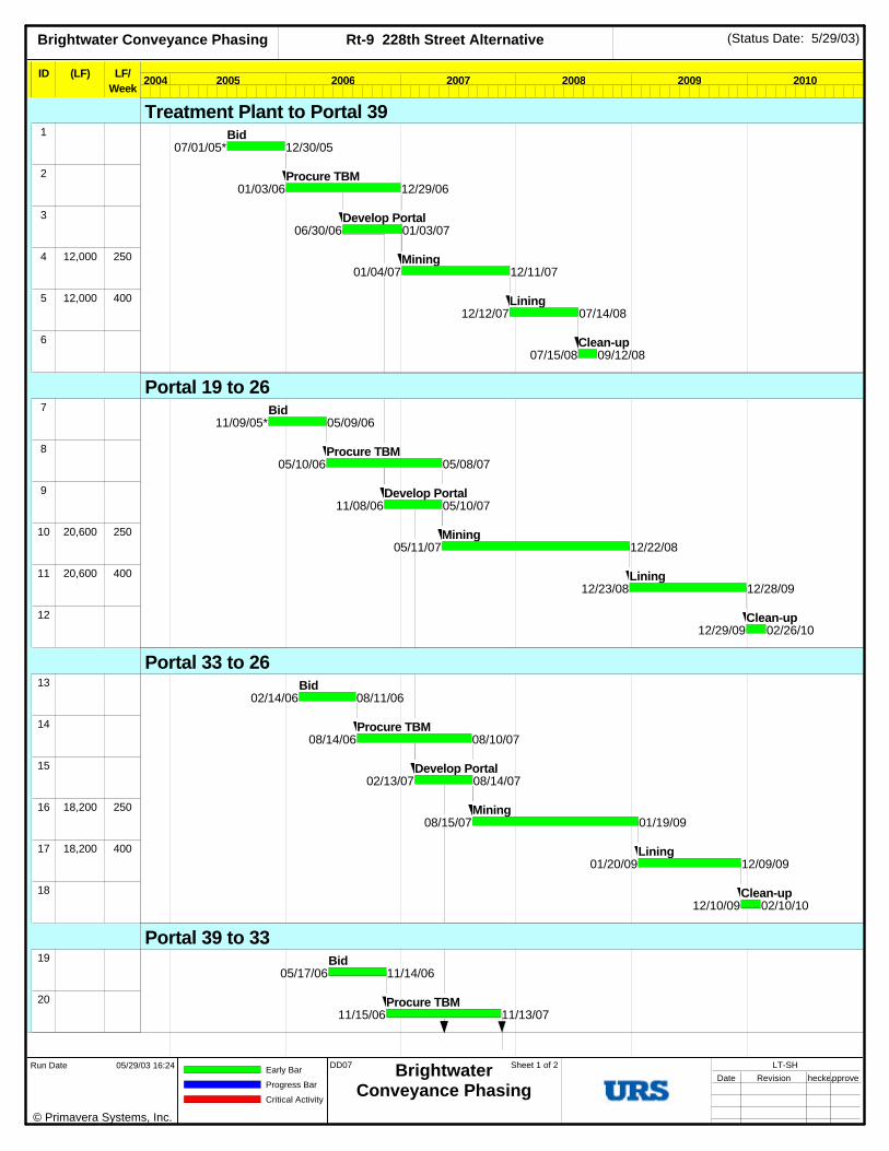
Brightwater Conveyance Phasing Rt-9 228th Street Alternative (Status Date: 5/29/03)
ActivityID
ID (LF) LF/Week
SHAA1
2
3
4 12,000 250
5 12,000 400
6
SHAB7
8
9
10 20,600 250
11 20,600 400
12
SHBA13
14
15
16 18,200 250
17 18,200 400
18
SHCA19
20
2004 2005 2006 2007 2008 2009 2010
07/01/05* 12/30/05Bid
01/03/06 12/29/06Procure TBM
06/30/06 01/03/07Develop Portal
01/04/07 12/11/07Mining
12/12/07 07/14/08Lining
07/15/08 09/12/08Clean-up
11/09/05* 05/09/06Bid
05/10/06 05/08/07Procure TBM
11/08/06 05/10/07Develop Portal
05/11/07 12/22/08Mining
12/23/08 12/28/09Lining
12/29/09 02/26/10Clean-up
02/14/06 08/11/06Bid
08/14/06 08/10/07Procure TBM
02/13/07 08/14/07Develop Portal
08/15/07 01/19/09Mining
01/20/09 12/09/09Lining
12/10/09 02/10/10Clean-up
05/17/06 11/14/06Bid
11/15/06 11/13/07Procure TBM
Treatment Plant to Portal 39
Portal 19 to 26
Portal 33 to 26
Portal 39 to 33
© Primavera Systems, Inc.
Run Date 05/29/03 16:24 Early Bar
Progress Bar
Critical Activity
DD07 BrightwaterConveyance Phasing
Sheet 1 of 2 LT-SHDate Revision CheckedApproved

Brightwater Conveyance Phasing Rt-9 228th Street Alternative (Status Date: 5/29/03)
ActivityID
ID (LF) LF/Week
21
22 15,700 250
23 15,700 240
24
SHEA25
26
27
28 12,700 250
29 12,700 400
30
SHFA31
32
33
34 13,000 250
35 13,000 400
36
SHGA37
38
39
40 9,400 250
41 9,400 400
42
2004 2005 2006 2007 2008 2009 2010
05/16/07 11/15/07Develop Portal
11/16/07 02/10/09Mining
02/11/09 11/16/09Lining
11/17/09 01/19/10Clean-up
07/18/05* 01/16/06Bid
01/17/06 01/15/07Procure TBM
07/17/06 01/17/07Develop Portal
01/18/07 01/16/08Mining
01/17/08 08/28/08Lining
08/29/08 10/29/08Clean-up
08/11/06 02/09/07Bid
02/12/07 02/08/08Procure TBM
08/10/07 02/12/08Develop Portal
02/13/08 02/18/09Mining
02/19/09 10/08/09Lining
10/09/09 12/09/09Clean-up
11/06/06 05/04/07Bid
05/07/07 05/02/08Procure TBM
11/05/07 05/06/08Develop Portal
05/07/08 02/02/09Mining
02/03/09 07/20/09Lining
07/21/09 09/18/09Clean-up
Portal 41 to Treatment Plant
Portal 44 to 41
Portal 11 to 44

Brightwater Conveyance Phasing Unocal Alternative (Status Date: 5/29/03)
ID (LF) LF/Week
SGAA1
2
3
4 11,090 250
5 11,090 400
6
SGBA7
8 15,310 250
9 15,310 400
10
SGCA11
12
13 16,900 250
14 16,900 400
15
SGDA16
17
18 17,950 250
19 17,950 400
20
2004 2005 2006 2007 2008 2009 2010
05/02/05* 10/28/05Bid
10/31/05 10/27/06Procure TBM
05/01/06 10/31/06Develop Portal
11/01/06 09/14/07Mining
09/17/07 04/01/08Lining
04/02/08 06/02/08Clean-up
09/17/07 11/12/07Move TBM
11/13/07 01/26/09Mining
01/27/09 10/23/09Lining (44 to 41)
10/26/09 12/23/09Clean-up
08/01/05* 01/31/06Bid
02/01/06 01/31/07Procure TBM
02/01/07 05/28/08Mining
05/29/08 03/27/09Lining
03/30/09 05/26/09Clean-up
04/03/06* 09/29/06Bid
10/02/06 10/01/07Procure TBM
10/02/07 02/26/09Mining
02/27/09 01/14/10Lining
01/15/10 03/15/10Clean-up
Treatment Plant to Portal 3
Portal 7 to 3
Portal 11 to 7
Portal 14 to 11
© Primavera Systems, Inc.
Run Date 05/29/03 16:26 Early Bar
Progress Bar
Critical Activity
DD07 BrightwaterConveyance Phasing
Sheet 1 of 2 LT-SGDate Revision CheckedApproved

Brightwater Conveyance Phasing Unocal Alternative (Status Date: 5/29/03)
ID (LF) LF/Week
SGEA21
22
23
SGFA24
25
2004 2005 2006 2007 2008 2009 2010
08/01/06* 01/30/07Bid
01/31/07 07/31/07Develop Portal
08/01/07 08/31/07Receive TBM's
04/01/08* 09/30/08Bid
10/01/08 02/26/10Construction
Portal 3
Tie-in's, Flow Control, Odor Control

Brightwater Construction Approach and Schedule King County Department of Natural Resources
Wastewater Treatment Division
5/03 Technical Memorandum
Page 44
5 - CONSTRUCTION TRAFFIC
Given the construction methods described above, vehicle traffic related to the construction activities at each portal was estimated. Construction traffic is broken into four major categories of trips:
1. Earthwork – This category provides the number of trucks hauling spoils off the portal site. Initial quantities for each segment are the excavated materials from the working shaft at the portal. After developing the portal, excavation of the tunnel proceeds at an average rate of 50 feet per day. The average daily excavated quantities are calculated as the surface area of the bore times the length of the bore each day (50 feet). Since in-place soils are compact, it is estimated that they will “swell” by about 30% when excavated, so haul quantities are 30% more than the in-place calculation. It is assumed that all excavated materials will be hauled by double truck and trailer combinations with a capacity of 20 cubic yards. However, the load per truck is calculated at 16 cubic yards to allow for plenty of freeboard or for wet soils, which are heavier.
2. Concrete – Cast-in-place (CIP) concrete may be used for secondary linings for some portions of the system. It is also used to fill voids between the various lining systems. In tunnel configurations with pipes inside the tunnels, the space inside the tunnel that is not taken up by pipes is filled with concrete. For concrete operations, it is assumed that standard mixing trucks will be used. Although these trucks have a capacity of 10 cubic yards, the calculation for the number of trucks is based on 9 cubic yards per truck. This provides a conservatively high estimate of the number of trucks and allows for some waste concrete in each load.
3. Other materials – The main materials required for the conveyance system are the linings for the tunnels. As excavation proceeds, the initial concrete liner segments are delivered. It is assumed that a single, complete ring, consisting of 6 segments each 4 feet long, will be delivered on one truck. For the smaller tunnels, it will take an average of six trucks per day to keep up with the rate of tunneling production of 50 feet per day. For larger tunnels (20 ft in diameter or larger), segments will be much larger so 12 trucks per day are anticipated for the initial lining system.
For the tunnel configurations that have pipes as final liners, it is assumed that the pipes will be delivered in 40-foot segments. Depending on the size of the pipe, there will be only one or two pipes per truck. Since lining rates for segments with a single pipe are anticipated to be 80 feet per day (400 feet/week), pipe deliveries for these segments will require 2 trucks per day. For segments with multiple pipes, the anticipated rate of progress is 240 feet/week, and will require up to 5 pipes per segment and 30 pipe sections per week. These segments will require 3 trucks per day, one truck for each of the effluent pipes and one truck for the influent pipe(s).
Over the course of the tunneling, other materials will be delivered including gaskets, lubricants, nuts and bolts, equipment, equipment parts, etc. In calculating total truck

Brightwater Construction Approach and Schedule King County Department of Natural Resources
Wastewater Treatment Division
5/03 Technical Memorandum
Page 45
traffic, it is estimated that an additional 3 trucks per day will come to the site for such miscellaneous deliveries.
4. Personnel vehicles – Based on tunneling experience, crew sizes were estimated for each major tunneling operation. For the mining operation, it is estimated that a crew of 24 to 28 workers will be needed. A somewhat smaller crew size would work night shifts. In addition to work crews, 10 to 12 management and inspection personnel representing the contractor, as well as the agency will work at each portal site. For a large tunnel segment, the on-site personnel are expected to have a peak of 40 people on day shift and 30 people on night shift. Again assuming average vehicle occupancy of 1.3 people, about 32 parking spaces are needed at each portal site. Shifts would overlap somewhat to optimize parking availability and minimize peak trips at each site.
Graphs
The attached graphs depict the numbers of each type of construction traffic described above for each portal where work is anticipated. They show traffic over the entire construction duration for each of the conveyance alternatives. It should be noted that the truck traffic associated with earthwork, concrete and material deliveries will be spread over the entire workday and deliveries can be scheduled to avoid peak traffic periods. Vehicles for personnel are limited to the start and completion of work shifts and will arrive at or leave the site within a relatively short time frame.

Land Conveyance Vehicle Traffic - 195th St. Portal 11
0
10
20
30
40
50
60
70
80
4/06 7/06 10/06 1/07 4/07 7/07 10/07 1/08 4/08 7/08 10/08 1/09 4/09 7/09 10/09 1/10
Veh
icle
s/D
ay
Earthwork Trucks Concrete Trucks Materials Trucks Personnel Vehicles Total Vehicles
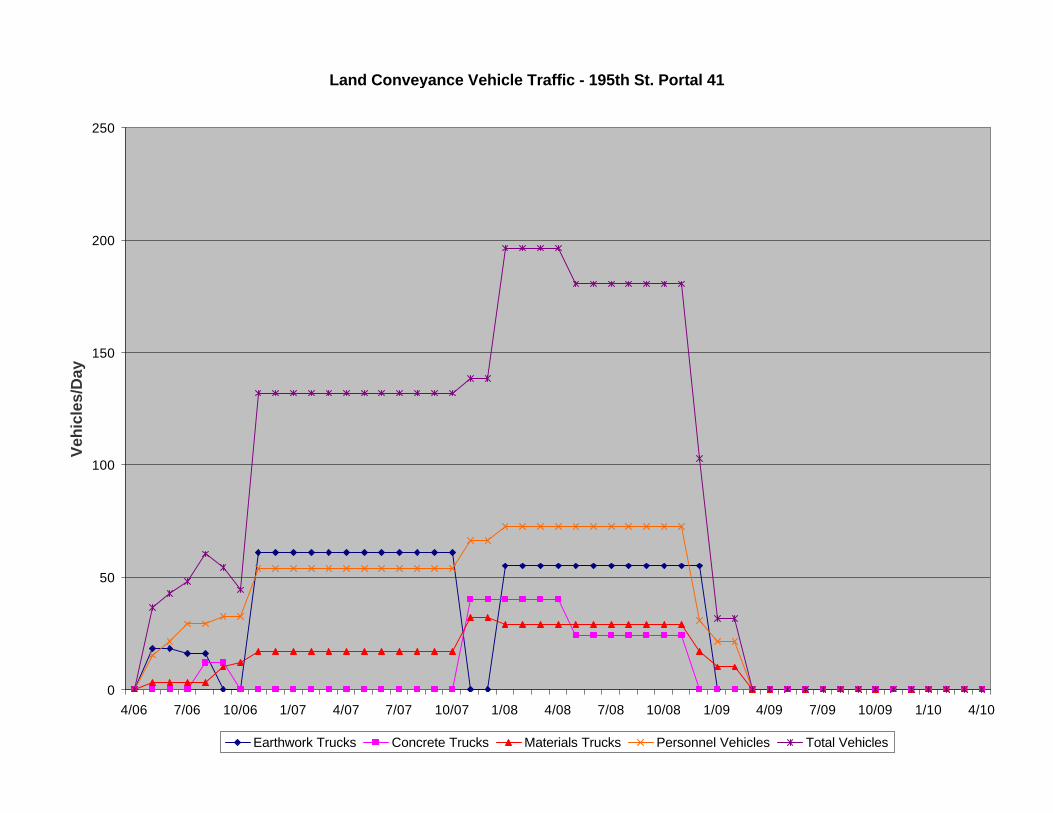
Land Conveyance Vehicle Traffic - 195th St. Portal 41
0
50
100
150
200
250
4/06 7/06 10/06 1/07 4/07 7/07 10/07 1/08 4/08 7/08 10/08 1/09 4/09 7/09 10/09 1/10 4/10
Veh
icle
s/D
ay
Earthwork Trucks Concrete Trucks Materials Trucks Personnel Vehicles Total Vehicles
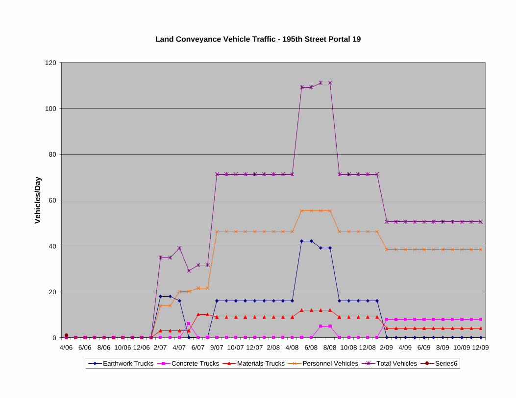
Land Conveyance Vehicle Traffic - 195th Street Portal 19
0
20
40
60
80
100
120
4/06 6/06 8/06 10/06 12/06 2/07 4/07 6/07 9/07 10/07 12/07 2/08 4/08 6/08 8/08 10/08 12/08 2/09 4/09 6/09 8/09 10/09 12/09
Veh
icle
s/D
ay
Earthwork Trucks Concrete Trucks Materials Trucks Personnel Vehicles Total Vehicles Series6

Land Conveyance Vehicle Traffic - 195th St. Portal 44
0
20
40
60
80
100
120
4/06 7/06 10/06 1/07 4/07 7/07 10/07 1/08 4/08 7/08 10/08 1/09 4/09 7/09 10/09 1/10 4/10
Veh
icle
s/D
ay
Earthwork Trucks Concrete Trucks Materials Trucks Personnel Vehicles Total Vehicles

Land Conveyance Vehicle Traffic - 195th St. Portal 5
0
10
20
30
40
50
60
70
4/06 7/06 10/06 1/07 4/07 7/07 10/07 1/08 4/08 7/08 10/08 1/09 4/09 7/09 10/09 1/10 4/10
Veh
icle
s/D
ay
Earthwork Trucks Concrete Trucks Materials Delivery Personnel Vehicles Total Vehicles

Land Conveyance Microtunnel Vehicles 195th St.
0
5
10
15
20
25
30
4/06 6/06 8/06 10/06 12/06 2/07 4/07 6/07 9/07 10/07 12/07 2/08 4/08 6/08 8/08 10/08 12/08 2/09 4/09 6/09 8/09
Veh
icle
s/D
ay
Earthwork Trucks Concrete Trucks Materials Trucks Personnel Vehicles Total Vehicles

Land Conveyance - Total Vehicles 195th St.
0
100
200
300
400
500
600
4/06 7/06 10/06 1/07 4/07 7/07 10/07 1/08 4/08 7/08 10/08 1/09 4/09 7/09 10/09 1/10 4/10
Veh
icle
s/D
ay
Earthwork Trucks Concrete Trucks Materials Trucks Personnel Vehicles Total Vehicles

Treatment Plant Portal Vehicle Traffic - 228th St. Alternative
0
10
20
30
40
50
60
70
80
90
4/06 6/06 8/06 10/06 12/06 2/07 4/07 6/07 9/07 10/07 12/07 2/08 4/08 6/08 8/08 10/08 12/08 2/09 4/09 6/09 8/09 10/09 12/09 2/10
Veh
icle
s/D
ay
Earthwork Trucks Concrete Trucks Materials Trucks Personnel Vehicles Total Vehicles

Land Conveyance Vehicle Traffic - 228th St. Alternative Portal 41
0
10
20
30
40
50
60
70
80
90
6/06 8/06 10/06 12/06 2/07 4/07 6/07 9/07 10/07 12/07 2/08 4/08 6/08 8/08 10/08 12/08 2/09 4/09 6/09 8/09 10/09 12/09 2/10
Veh
icle
s/D
ay
Earthwork Trucks Concrete Trucks Materials Trucks Personnel Vehicles Total Vehicles

Land Conveyance Vehicle Traffic - 228th St. Alternative Portal 44
0
10
20
30
40
50
60
70
80
90
4/06 6/06 8/06 10/0612/06 2/07 4/07 6/07 9/07 10/0712/07 2/08 4/08 6/08 8/08 10/0812/08 2/09 4/09 6/09 8/09 10/0912/09 2/10 4/10
Veh
icle
s/D
ay
Earthwork Trucks Concrete Trucks Materials Trucks Personnel Vehicles Total Vehicles
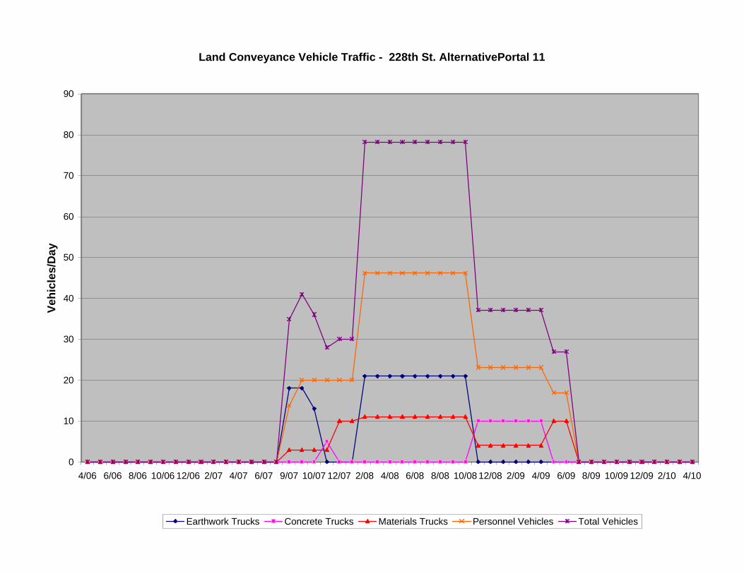
Land Conveyance Vehicle Traffic - 228th St. AlternativePortal 11
0
10
20
30
40
50
60
70
80
90
4/06 6/06 8/06 10/06 12/06 2/07 4/07 6/07 9/07 10/07 12/07 2/08 4/08 6/08 8/08 10/08 12/08 2/09 4/09 6/09 8/09 10/09 12/09 2/10 4/10
Veh
icle
s/D
ay
Earthwork Trucks Concrete Trucks Materials Trucks Personnel Vehicles Total Vehicles

Land Conveyance Vehicle Traffic - 228th St. Alternative Portal 19
0
20
40
60
80
100
120
4/06 6/06 8/06 10/06 12/06 2/07 4/07 6/07 9/07 10/07 12/07 2/08 4/08 6/08 8/08 10/08 12/08 2/09 4/09 6/09 8/09 10/09 12/09 2/10 4/10
Veh
icle
s/D
ay
Earthwork Trucks Concrete Trucks Materials Trucks Personnel Vehicles Total Vehicles

Land Conveyance Vehicle Traffic - 228th St. Alternative Portal 33
0
10
20
30
40
50
60
70
80
4/06 6/06 8/06 10/06 12/06 2/07 4/07 6/07 9/07 10/07 12/07 2/08 4/08 6/08 8/08 10/08 12/08 2/09 4/09 6/09 8/09 10/09 12/09 2/10 4/10
Veh
icle
s/D
ay
Earthwork Trucks Concrete Trucks Materials Trucks Personnel Vehicles Total Vehicles

Land Conveyance Vehicle Traffic - 228th St. Alternative Portal 39
0
10
20
30
40
50
60
70
80
90
4/06 6/06 8/06 10/0612/06 2/07 4/07 6/07 9/07 10/0712/07 2/08 4/08 6/08 8/08 10/0812/08 2/09 4/09 6/09 8/09 10/0912/09 2/10 4/10
Veh
icle
s/D
ay
Earthwork Trucks Concrete Trucks Materials Trucks Personnel Vehicles Total Vehicles

Land Conveyance Vehicle Traffic - 228th St. Alternative Portal 26
0
5
10
15
20
25
30
35
40
4/06 6/06 8/06 10/06 12/06 2/07 4/07 6/07 9/07 10/07 12/07 2/08 4/08 6/08 8/08 10/08 12/08 2/09 4/09 6/09 8/09 10/09 12/09 2/10 4/10
Veh
icle
s/D
ay
Earthwork Trucks Concrete Trucks Materials Delivery Personnel Vehicles Total Vehicles

Total Construction Traffic 228th Street Alternative
0
50
100
150
200
250
300
350
400
450
500
4/06 6/06 8/06 10/0612/06 2/07 4/07 6/07 9/07 10/0712/07 2/08 4/08 6/08 8/08 10/0812/08 2/09 4/09 6/09 8/09 10/0912/09 2/10 4/10
Veh
icle
s/D
ay
Earthwork Trucks Concrete Trucks Materials Trucks Personnel Vehicles Total Vehicles
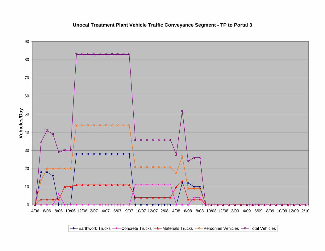
Unocal Treatment Plant Vehicle Traffic Conveyance Segment - TP to Portal 3
0
10
20
30
40
50
60
70
80
90
4/06 6/06 8/06 10/06 12/06 2/07 4/07 6/07 9/07 10/07 12/07 2/08 4/08 6/08 8/08 10/08 12/08 2/09 4/09 6/09 8/09 10/09 12/09 2/10
Veh
icle
s/D
ay
Earthwork Trucks Concrete Trucks Materials Trucks Personnel Vehicles Total Vehicles

Unocal Vehicle Traffic - Portal 3 (Receiving Portal)
0
5
10
15
20
25
30
35
40
4/06 7/06 10/06 1/07 4/07 7/07 10/07 1/08 4/08 7/08 10/08 1/09 4/09 7/09 10/09 1/10 4/10
Veh
icle
s/D
ay
Earthwork Trucks Concrete Trucks Materials Delivery Personnel Vehicles Total Vehicles

Unocal Vehicle Traffic - Portal 14
0
10
20
30
40
50
60
70
80
90
4/06 6/06 8/06 10/0612/06 2/07 4/07 6/07 9/07 10/0712/07 2/08 4/08 6/08 8/08 10/0812/08 2/09 4/09 6/09 8/09 10/0912/09 2/10 4/10
Veh
icle
s/D
ay
Earthwork Trucks Concrete Trucks Materials Trucks Personnel Vehicles Total Vehicles

Unocal Vehicle Traffic - Portal 11
0
10
20
30
40
50
60
70
80
4/06 6/06 8/06 10/06 12/06 2/07 4/07 6/07 9/07 10/07 12/07 2/08 4/08 6/08 8/08 10/08 12/08 2/09 4/09 6/09 8/09 10/09 12/09
Veh
icle
s/D
ay
Earthwork Trucks Concrete Trucks Materials Trucks Personnel Vehicles Total Vehicles

Unocal Vehicle Traffic - Portal 7
0
10
20
30
40
50
60
70
80
90
4/06 7/06 10/06 1/07 4/07 7/07 10/07 1/08 4/08 7/08 10/08 1/09 4/09 7/09 10/09 1/10 4/10
Veh
icle
s/D
ay
Earthwork Trucks Concrete Trucks Materials Trucks Personnel Vehicles Total Vehicles

Total Construction Traffic - Unocal Alternative
0
50
100
150
200
250
300
350
4/06 6/06 8/06 10/0612/06 2/07 4/07 6/07 9/07 10/0712/07 2/08 4/08 6/08 8/08 10/0812/08 2/09 4/09 6/09 8/09 10/0912/09 2/10 4/10
Veh
icle
s/D
ay
Earthwork Trucks Concrete Trucks Materials Trucks Personnel Vehicles Total Vehicles
Brightwater Construction Approach and Schedule King County Department of Natural Resources
Wastewater Treatment Division
5/03 Technical Memorandum
Page 68
6 - CONSTRUCTION APPROACH – MARINE OUTFALLS
Two areas, called outfall zones, have been identified as potential locations for the placement of the Brightwater Outfall. Each outfall zone extends approximately 5,000 feet into Puget Sound from the Sound’s eastern shoreline in northern King County and southern Snohomish County. Outfall Zone 7S would be utilized if the alternatives (195th Street preferred alternative and the 228th Street alternative) associated with the Route 9 treatment plant was selected. Outfall Zone 6 would be utilized if the Brightwater treatment plant were located at the Unocal site. The marine outfall is anticipated to be a 60-inch diameter pipeline. Its construction can be separated into three main components: onshore, nearshore and offshore.
Onshore Construction
For the Route 9 alternatives, the onshore segment of the outfall starts at the proposed portal 19 sites, where it interfaces with the land conveyance system. The pipeline traverses the onshore area from proposed portal 19 to the seawall just south of the existing dock. The length of the onshore segment is approximately 1,100 LF, and approximately 30 ft deep at the structure connecting the outfall to the conveyance tunnel at portal 19. The onshore pipe segment will be built using either cut and cover (open trench) methodology or microtunneling.
For the Unocal alternative, the onshore segment of the outfall starts at the effluent pump station and traverses the onshore area, again in a sheeted trench, to the shoreline just north of the existing Unocal pier. The pump station connection is approximately 1,000 LF and measures a depth of about 15 feet. The onshore segment of the Unocal outfall passes under the BNSF railroad and a section of approximately 80 to 100 feet would be constructed under the railroad using jack and bore technology.
If cut and cover methods are used, the trench will be tight-sheeted using sheet piles to a depth of about 20 feet below the bottom of the trench. Continuous dewatering of the trench will be necessary during pipe-laying operations and concrete bedding, which will likely be installed to control water below the pipe. The pipe will be installed and the trench backfilled, possibly using controlled density fill (CDF). If buoyancy is an issue, a foundation and tie-down system may be used to anchor the pipe.
Sheet piles will limit the width of the trench and minimize excavation and subsequent backfill operations. For the Route 9 alternative, the trench would be approximately 12 feet wide by 30 feet deep and 1,100 feet in length. A total of nearly 15,000 cubic yards of soils will be excavated, requiring about 21 truck-trips per day over a 2-month construction period. About the same number of trucks will be required for hauling fill materials to the onshore trench. In total, onshore construction for the Route 9 alternative will generate an average of about 40 truck trips per day over a period of about 2 months. For the Unocal alternative, the excavation will only be about 15 feet deep, so the number of trucks trips will be about half of those for Route 9, or 20 trips per day for a 2-month construction duration.
Brightwater Construction Approach and Schedule King County Department of Natural Resources
Wastewater Treatment Division
5/03 Technical Memorandum
Page 69
Nearshore Construction
The nearshore segment runs from the seaward side of the seawall to a depth of approximately –80 feet MLLW. For the Route 9 alternative, the length of the nearshore construction is estimated to be about 450 LF. It will be about 850 LF for the Unocal alternative. The in-water construction activities can be performed either by equipment operating from barges or from a temporary trestle pier that could extend into the water from the shoreline as excavation and pipeline installation progresses. The construction method selected would depend on water depth, land access, and contractor preference and experience. Both barge and trestle installation methods would likely utilize trench sheeting in which large interlocking metal “sheets,” called sheet piles, would be driven into the seafloor to minimize the trench width and disturbance to the nearshore habitat.
Open-trench construction through the nearshore includes excavation of the trench, pipeline installation, trench backfilling and pipeline protection, and restoration of the trench surface. If required, trench shoring can also be installed ahead of the trench excavation to minimize the extent of damage to the seafloor along the trench alignment.
Since the construction methods and equipment used for both barge-mounted and trestle pipeline installation are very similar, the following discussion can be applied to both methods. Differences in construction activities or equipment between the methods are identified and discussed.
Staging Area
A land-based staging area located near the proposed conveyance tunnel terminus (Zone 7S) or proposed effluent pump station (Zone 6) would be required if trestle construction were utilized to excavate the nearshore trench. Materials and supplies could be transported between the staging area and trestle along a conveyor system. Barge-mounted construction activities may also use a land-based staging area. However, it is most likely that trench excavation and pipeline installation would be supported offshore via supply and storage barges.
Activities at the land-based staging area, utilized at the contractor’s option, could include assembly of pipeline structures, loading and unloading of trucks carrying materials, storage of construction materials, and storage of construction machinery such as trucks, cranes, and backhoes. The staging area could also hold construction offices for King County and contractor personnel. The staging area could be in use for the duration of onshore, nearshore, and offshore construction.
Trench Sheeting
Sheet piles can be utilized to minimize environmental impacts to sensitive nearshore habitat. The sheets are driven into the seafloor to minimize trench section width and prevent surrounding soil and sediment from sloughing into the trench during excavation. Trench sheeting would extend above the seafloor and, at the contractor’s option, could extend to or above the water surface. This extension to the water surface makes the trench more visible and should lessen the time required for construction. The presence of the materials above water should not interrupt marine traffic. After pipe installation and backfill, the trench sheets would be removed.

Brightwater Construction Approach and Schedule King County Department of Natural Resources
Wastewater Treatment Division
5/03 Technical Memorandum
Page 70
The most common types of equipment used to install sheet pile walls are vibratory hammers and impact hammers, both of which could be used on barges as well as a trestle. Vibratory hammers are widely used to drive the piles faster, do not damage the top of the pile, and can easily be extracted.
Unsheeted trench installation could disturb a width of 60 to 100 feet along the length of the pipeline. Sheeted trench installation could reduce the seabed impact to approximately a width of 20 to 25 feet along the length of the pipeline. See Figure 9 (located at the end of this document) for cross-sections of sheeted and unsheeted trench construction.
Barges
Barge supported trench excavation would require a “working barge” along with several support barges. Tugboats would be used for moving barges to and from the site and for positioning of the working barge. The working barge would be equipped with a crane for laying pipeline segments and excavating the trench. The support barges would be used to supply the working barge with pipeline segments and backfill material while additional barges could store excavated soils for use as backfill or transport to the disposal site.
The working barge could be anchored to the seafloor with “spuds.” Spuds act like pins sticking into the seafloor below the barge and can be used up to water depths of –60 feet. Spuds can be raised and lowered to allow movement of the working barge. Typically, the barge could be pushed into shallow water by working tugs. Two anchors would be placed offshore to allow positioning “pull.” The spuds are then utilized to allow control of the angular position of the barge relative to the trench direction. Since the spuds move up and down vertically from the barge, no additional footprint space would be required. However, the spuds could cause additional damage to the seafloor itself. Penetration of the spuds into the seafloor may reach 3 or 4 feet, depending on soil conditions. For barges supplying the working barge, or for barges working beyond water depths of 60 feet, four to six anchor lines could be used. Anchor lines extend from the barge in several directions and are typically up to 1,000 feet long. Anchor lines could be up to 2,000 feet long.
Excavation Equipment
The excavation of a pipeline trench would likely be performed using mechanical excavation equipment. Mechanical excavators, such as clamshell type equipment, are the most common types of equipment used in marine excavation and pipe laying applications. Mechanical equipment can be mounted on a trestle or barges and can be used successfully with both hard and soft materials.
Selection of the type of equipment used to perform the excavation will depend on the following factors:
• Physical properties of the excavated material. • Quantities of material to be excavated. • Distance for transport to the disposal area. • Presence and concentration of contamination (meet PSDDA requirements).

Brightwater Construction Approach and Schedule King County Department of Natural Resources
Wastewater Treatment Division
5/03 Technical Memorandum
Page 71
• Equipment readily available to contractors. • Cost. • Turbidity impacts.
Excavated Material Storage and Transportation
Barges, used in conjunction with mechanical excavation equipment, have been the most widely used methods of transporting large quantities of excavated material in Puget Sound. Barges could also be the most likely means of storing excavated material that would be utilized for backfill of the pipeline, once installed. Based on very limited information concerning the specific bottom soil properties, it is anticipated that the native material to be excavated could be suitable for a portion of the backfill, assuming its use would conform to regulatory requirements. Disposal of excavated material offsite will be required since at least some of the excavated material will be in excess of that necessary for backfill.
• Open Water Disposal- The most viable method of excavated marine soil disposal is that allowed in open water. Soil disposal is regulated by the United States Army Corps of Engineers (COE), and must occur at regulated disposal sites. The exact location of the disposal site will be determined through the permitting process. Materials must meet contamination levels below those promulgated by the Puget Sound Dredge Disposal Analysis (PSDDA).
• Upland Disposal- If open-water disposal were not feasible, excavated soils could be disposed of on land at regulated landfill sites. The landfill site would be selected based on the presence, if any, and concentration of contaminants in the excavated soils. Due to increased land disposal costs, upland disposal should not be considered as the primary option.
Bedding and Pipe Protection
Subject to permit limitations, native material may be suitable for backfill of the trench above the bedding and armoring zone. Armoring of the pipeline may be necessary in water depths up to approximately –50 feet MLLW. Armoring is provided to protect the pipeline from wave action, erosion, and anchor damage by both small boats and larger vessels, as appropriate. The selected bedding and armoring material is selected based on the full consideration and nature of existing soils, current conditions, and historical evidence of erosion. Crushed material without fines is considered ideal as bedding and armoring material. Care should be taken to limit the use of unsuitable material, which could ultimately cause turbidity issues upon placement in the water. Imported materials for the pipe-bedding zone could be placed by clamshell. Pipeline armoring material could be similarly placed.
Method Characteristics and Limitations
Trench construction and pipeline installation can be utilized for all of the Brightwater outfall pipeline diameter and material alternatives. Trench construction is not limited in terms of the nearshore segment length.
Staging area and access requirements for trench construction are similar, but likely not as large as

Brightwater Construction Approach and Schedule King County Department of Natural Resources
Wastewater Treatment Division
5/03 Technical Memorandum
Page 72
for tunnel construction. Adequate space for storage of pipeline segments, backfill material, and excavated material is available at any of the potential conveyance tunnel terminus areas. If access were limited, trench excavation and pipeline installation could be supported from the water by several barges.
Surface and subsurface soil properties should not have a significant impact on trench excavation. Mechanical excavation equipment is suitable for both hard and soft materials. The presence of boulders along the nearshore outfall segment may impact installation of sheet piles.
Construction Schedule and Rate of Construction
Construction of the nearshore outfall for an alignment based on a portal location for the proposed Point Wells site alternative, or UNOCAL site could occur over a single construction season, based on the time allocated for construction by the Washington State Department of Fish and Wildlife, United States Fish and Wildlife Service, and the National Marine Fisheries Service. It may be that in order to meet the time constraints imposed by Fisheries, construction activities for some items must occur on a 24-hour-per-day basis.
Offshore Construction
At approximately 80 feet below MLLW, the buried pipe will emerge from the nearshore trench and will continue on the sea floor to its final depth of over 600 feet below sea level. The offshore segment of the proposed outfall alignments extends from the end of the nearshore segment and terminates at the end of the diffuser. The offshore outfall segment would be placed directly on the seabed and would not require excavation. The diffuser segment would be installed along with the offshore pipeline utilizing the same offshore construction method.
Potential outfall alignments may cross known utility cable areas established by the United States Army Corps of Engineers (COE). Short, bridged sections of offshore pipeline can span identified in-water utility cables to prevent damage during outfall construction and operation. The offshore segment, including the 500 LF diffuser section, for both alternatives is between 4,300 and 4,900 LF.
Three potential offshore construction methods may be used on this project. Depending on the offshore construction method selected, a land-based staging area may be required for fabrication of pipeline segments and storage of construction materials and equipment. The staging area may be located at the same staging area used for nearshore construction or may be located near a convenient offsite location near a sheltered harbor. Construction machinery and equipment includes tugboats, barges, welding equipment, cranes, flotation devices, and artificial lighting.
Potential pipeline installation methods for the offshore pipeline segment include segmental lay, controlled submergence, and bottom pull.
Segmental Lay
Pipelines constructed by the segmental lay method require the use of divers and robotics to make underwater connections between pipeline segments as the pipes are placed on the seabed. Robotics would be used at water depths below approximately –200 feet MLLW due to limitations on diver time at

Brightwater Construction Approach and Schedule King County Department of Natural Resources
Wastewater Treatment Division
5/03 Technical Memorandum
Page 73
such depths. Several barge mounted cranes would be used to lower pipeline segments (100 to 500 feet in length) while other barges would supply material to the working barge. Segmental lay construction would not require a nearby land-based staging area, as construction materials and equipment for support of pipeline installation could be supplied from the water. A land-based staging area at a convenient offsite location would be necessary for assembly of the 100- to 500-foot pipe segments.
Controlled Submergence
The controlled submergence method involves the fabrication of the entire outfall pipeline either onshore or at a convenient offsite location in a sheltered harbor. The pipeline would be floated from land or the sheltered waters and towed into place at the desired outfall zone. Once in place, the pipeline would be lowered (sunk) in a controlled manner while being positioned to settle on the seabed starting from the nearshore and ending at the diffuser. Buoyancy of the outfall pipeline during towing could be accomplished by filling the pipeline with air or by utilizing flotation devices. The floating pipeline could be towed into place by multiple tug boats (one boat at each end of the pipeline).
Bottom Pull
Bottom pull involves the fabrication of long sections of pipeline onshore at the location where the connection will be made with the upland conveyance pipeline. These fabricated sections would be pulled offshore down the existing slope of Puget Sound to the outfall end point (diffuser location). The pull is facilitated by maintaining a small negative buoyancy (5 to 10 pounds per foot) of the pipeline because pulling a fully weighted pipeline along the seabed could abrade the pipeline coatings used for corrosion protection and impose unnecessary flexing of the pipeline itself due to its own weight.
Construction Duration Assuming no significant delays (inclement weather, accidents, and construction material supply difficulties) are encountered, total time of actual construction (not including material and equipment procurement) for all potential outfall and diffuser pipeline alignments is estimated at 10 to 12 months. An additional 6 to 12 months may be required for pipe delivery and procurement of specialized equipment.
The sequence of construction activities relative to different areas of the outfall alignment (onshore, nearshore, and offshore) is dependent upon the construction method, outfall staging area and alignment, and contractor preference. Typically, mobilization, material, and equipment delivery would begin 1 to 3 months before the start of the open-trench or tunnel construction. Material and equipment delivery are likely to continue concurrently with other open-trench, tunnel, and offshore construction activities. Construction of the offshore segment could proceed concurrently with the nearshore and onshore work. Restoration and demobilization typically occur as construction segments are completed. These activities may proceed for an additional 1 to 2 months after the other construction activities are completed.
Preliminary construction schedule estimates for trench, tunnel, and offshore construction activities are presented in Table 3. Duration estimates given as a range in Table 3 reflect differences in pipeline length for the potential outfall alignments. Because some construction activities could take place at the same time, total construction duration is not the sum of the individual activities.

Brightwater Construction Approach and Schedule King County Department of Natural Resources
Wastewater Treatment Division
5/03 Technical Memorandum
Page 74
Table 3:
Preliminary Construction Schedule Estimates
Activity Duration (months)
Trench Construction
Material/Equipment Delivery 2
Mobilization 1-2
Dewatering 2
Onshore Trench 1-2
Nearshore Trench 2-3
Demobilization/Restoration 1-2
Tunnel Construction
Material/Equipment Delivery 2-3
Mobilization 1-2
Tunnel Boring 4-5
Demobilization/Restoration 1-2
Offshore Construction
Material/Equipment Delivery 4-5
Mobilization 1-2
Pipeline Fabrication/Installation (Controlled Submergence and Bottom Pull)
2-3
Pipeline Fabrication/Installation (Segmental Lay)
4-6
Demobilization/Restoration 1-2
Daily construction schedules differ for the potential construction methods. Construction during daylight hours (7:00 a.m. to 7:00 p.m.) would minimize the need for artificial lighting. Construction areas and barges may still utilize lighting for security, navigation, or operational purposes outside of typical construction hours. Although tunneling operations would require continuous construction (24 hours a day), a significant portion of tunneling activities would take place below the ground surface.

Brightwater Construction Approach and Schedule King County Department of Natural Resources
Wastewater Treatment Division
5/03 Technical Memorandum
Page 75
Typical construction hours for the potential construction methods would be as follows:
• Trench – Primarily daylight hours. • Tunnel – Continuous construction. • Segmental Lay – Primarily daylight hours. • Controlled Submergence – Primarily daylight hours (pipe fabrication) and continuous
construction for up to 1 week (pipeline installation). • Bottom Pull – Primarily daylight hours (pipe fabrication) and continuous construction for
up to 4 weeks (pipeline installation).