3. disassembly and reassembly€¦ · service manual 3-1 samsung electronics 3 3. disassembly and...
TRANSCRIPT

Disassembly and Reassembly
Service Manual 3-1Samsung Electronics
333. Disassembly and Reassembly
3.1 General Precautions on Disassembly
When you disassemble and reassemble compo-nents, you must use extreme caution. The closeproximity of cables to moving parts makes properrouting a must. If components are removed, any cables disturbedby the procedure must be restored as close aspossible to their original positions. Before remov-ing any component from the machine, note thecable routing that will be affected.
Whenever servicing the machine, you
must perform as follows:
1. Check to verify that documents are not storedin memory.
2. Be sure to remove the print cartridge beforeyou disassemble parts.
3. Unplug the power cord.
4. Use a flat and clean surface.
5. Replace only with authorized components.
6. Do not force plastic-material components.
7. Make sure all components are in their properposition.
Releasing Plastic Latches
Many of the parts are held in place with plasticlatches. The latches break easily; release themcarefully. To remove such parts, press the hook end of thelatch away from the part to which it is latched.
Service Manual
Disassembly and Reassembly
3-2 Samsung Electronics
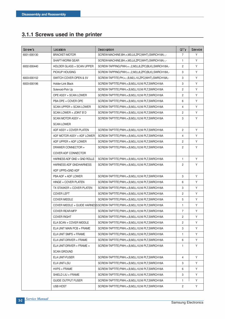
3.1.1 Screws used in the printer
6001-000130 BRACKET-MOTOR SCREW-MACHINE;BH,+,M3,L6,ZPC(WHT),SWRCH18A,-,- 7 Y
SHAFT-WORM GEAR SCREW-MACHINE;BH,+,M3,L6,ZPC(WHT),SWRCH18A,-,- 1 Y
6002-000440 HOLDER GLASS + SCAN UPPER SCREW-TAPPING;PWH,+,-,2,M3,L8,ZPC(BLK),SWRCH18A,- 2 Y
PICKUP HOUSING SCREW-TAPPING;PWH,+,-,2,M3,L8,ZPC(BLK),SWRCH18A,- 3 Y
6003-000152 SWITCH COVER OPEN & 5V SCREW-TAPTITE;PH,+,-,B,M2,L10,ZPC(WHT),SWRCH18A,- 3 Y
6003-000196 Holder-Link Black SCREW-TAPTITE;PWH,+,B,M3,L10,NI PLT,SWRCH18A 3 Y
Solenoid-Pick Up SCREW-TAPTITE;PWH,+,B,M3,L10,NI PLT,SWRCH18A 2 Y
OPE ASSY + SCAN LOWER SCREW-TAPTITE;PWH,+,B,M3,L10,NI PLT,SWRCH18A 2 Y
PBAOPE + COVER OPE SCREW-TAPTITE;PWH,+,B,M3,L10,NI PLT,SWRCH18A 6 Y
SCAN UPPER + SCAN LOWER SCREW-TAPTITE;PWH,+,B,M3,L10,NI PLT,SWRCH18A 4 Y
SCAN LOWER + JOINT B`D SCREW-TAPTITE;PWH,+,B,M3,L10,NI PLT,SWRCH18A 2 Y
SCAN MOTOR ASSY + SCREW-TAPTITE;PWH,+,B,M3,L10,NI PLT,SWRCH18A 3 Y
SCAN LOWER
ADF ASSY + COVER PLATEN SCREW-TAPTITE;PWH,+,B,M3,L10,NI PLT,SWRCH18A 2 Y
ADF MOTOR ASSY + ADF LOWER SCREW-TAPTITE;PWH,+,B,M3,L10,NI PLT,SWRCH18A 4 Y
ADF UPPER + ADF LOWER SCREW-TAPTITE;PWH,+,B,M3,L10,NI PLT,SWRCH18A 2 Y
DRAWER CONNECTOR + SCREW-TAPTITE;PWH,+,B,M3,L10,NI PLT,SWRCH18A 2 Y
COVER ADF CONNECTOR
HARNESS ADF GND + GND ROLLE SCREW-TAPTITE;PWH,+,B,M3,L10,NI PLT,SWRCH18A 1 Y
HARNESS ADF GND/HARNESS SCREW-TAPTITE;PWH,+,B,M3,L10,NI PLT,SWRCH18A 2 Y
ADF UPPE+GND ADF
PBAADF + ADF LOWER SCREW-TAPTITE;PWH,+,B,M3,L10,NI PLT,SWRCH18A 3 Y
HINGE + COVER PLATEN SCREW-TAPTITE;PWH,+,B,M3,L10,NI PLT,SWRCH18A 6 Y
TX STAXKER + COVER PLATEN SCREW-TAPTITE;PWH,+,B,M3,L10,NI PLT,SWRCH18A 3 Y
COVER LEFT SCREW-TAPTITE;PWH,+,B,M3,L10,NI PLT,SWRCH18A 2 Y
COVER MIDDLE SCREW-TAPTITE;PWH,+,B,M3,L10,NI PLT,SWRCH18A 5 Y
COVER MIDDLE + GUIDE HARNESSSCREW-TAPTITE;PWH,+,B,M3,L10,NI PLT,SWRCH18A 1 Y
COVER REAR-MFP SCREW-TAPTITE;PWH,+,B,M3,L10,NI PLT,SWRCH18A 7 Y
COVER RIGHT SCREW-TAPTITE;PWH,+,B,M3,L10,NI PLT,SWRCH18A 2 Y
ELASCAN + COVER MIDDLE SCREW-TAPTITE;PWH,+,B,M3,L10,NI PLT,SWRCH18A 2 Y
ELAUNIT MAIN PCB + FRAME SCREW-TAPTITE;PWH,+,B,M3,L10,NI PLT,SWRCH18A 3 Y
ELAUNIT SMPS + FRAME SCREW-TAPTITE;PWH,+,B,M3,L10,NI PLT,SWRCH18A 1 Y
ELAUNIT-DRIVER + FRAME SCREW-TAPTITE;PWH,+,B,M3,L10,NI PLT,SWRCH18A 6 Y
ELAUNIT-DRIVER + FRAME + SCREW-TAPTITE;PWH,+,B,M3,L10,NI PLT,SWRCH18A 1 Y
SCAN GROUND
ELAUNIT-FUSER SCREW-TAPTITE;PWH,+,B,M3,L10,NI PLT,SWRCH18A 4 Y
ELAUNIT-LSU SCREW-TAPTITE;PWH,+,B,M3,L10,NI PLT,SWRCH18A 3 Y
HVPS + FRAME SCREW-TAPTITE;PWH,+,B,M3,L10,NI PLT,SWRCH18A 6 Y
SHIELD LIU + FRAME SCREW-TAPTITE;PWH,+,B,M3,L10,NI PLT,SWRCH18A 3 Y
GUIDE OUTPUT FUSER SCREW-TAPTITE;PWH,+,B,M3,L10,NI PLT,SWRCH18A 1 Y
USB HOST SCREW-TAPTITE;PWH,+,B,M3,L10,NI PLT,SWRCH18A 2 Y

Disassembly and Reassembly
Service Manual 3-3Samsung Electronics
CAM-CATCH SCREW-TAPTITE;PWH,+,B,M3,L10,NI PLT,SWRCH18A 2 Y
COVER-GROUND OPC SCREW-TAPTITE;PWH,+,B,M3,L10,NI PLT,SWRCH18A 2 Y
ELAUNIT SMPS + FRAME SCREW-TAPTITE;PWH,+,B,M3,L10,NI PLT,SWRCH18A 1 Y
ELA-UNIT FUSER TERMINAL SCREW-TAPTITE;PWH,+,B,M3,L10,NI PLT,SWRCH18A 2 Y
GUIDE-HARNESS SCREW-TAPTITE;PWH,+,B,M3,L10,NI PLT,SWRCH18A 1 Y
HARNESS SCF SCREW-TAPTITE;PWH,+,B,M3,L10,NI PLT,SWRCH18A 2 Y
HOLDER-CAM SCREW-TAPTITE;PWH,+,B,M3,L10,NI PLT,SWRCH18A 1 Y
HOLDER-CLUTCH CAM SCREW-TAPTITE;PWH,+,B,M3,L10,NI PLT,SWRCH18A 1 Y
HOLDER-FEED&EMPTY SCREW-TAPTITE;PWH,+,B,M3,L10,NI PLT,SWRCH18A 2 Y
MEA FRAME-EXIT SCREW-TAPTITE;PWH,+,B,M3,L10,NI PLT,SWRCH18A 2 Y
PLATE-GND EXIT SCREW-TAPTITE;PWH,+,B,M3,L10,NI PLT,SWRCH18A 1 Y
PLATE-GND FUSER+100M SCREW-TAPTITE;PWH,+,B,M3,L10,NI PLT,SWRCH18A 1 Y
PLATE-GUIDE PICKUP SCREW-TAPTITE;PWH,+,B,M3,L10,NI PLT,SWRCH18A 2 Y
PLATE-SHAFT LACK SCREW-TAPTITE;PWH,+,B,M3,L10,NI PLT,SWRCH18A 2 Y
SOLENOID PICK-UP SCREW-TAPTITE;PWH,+,B,M3,L10,NI PLT,SWRCH18A 1 Y
6003-000269 BRACKET-DEVE CAP SCREW-TAPTITE;BH,+,-,S,M3,L6,ZPC(WHT),SWRCH18A,- 5 Y
HARNESS GND + BRACKET GEAR SCREW-TAPTITE;BH,+,-,S,M3,L6,ZPC(WHT),SWRCH18A,- 1 Y
MOTOR ADF + BRACKET GEAR SCREW-TAPTITE;BH,+,-,S,M3,L6,ZPC(WHT),SWRCH18A,- 2 Y
WHITE BAR + GROUND HARNESS SCREW-TAPTITE;BH,+,-,S,M3,L6,ZPC(WHT),SWRCH18A,- 1 Y
ELAUNIT MAIN PCB +DRIVE SCREW-TAPTITE;BH,+,-,S,M3,L6,ZPC(WHT),SWRCH18A,- 1 Y
MAIN PCB + MAIN LOWER SCREW-TAPTITE;BH,+,-,S,M3,L6,ZPC(WHT),SWRCH18A,- 4 Y
SMPS SCREW-TAPTITE;BH,+,-,S,M3,L6,ZPC(WHT),SWRCH18A,- 4 Y
PLATE-GUIDE PICKUP SCREW-TAPTITE;BH,+,-,S,M3,L6,ZPC(WHT),SWRCH18A,- 1 Y
6003-000282 INLET-SWITCH SCREW-TAPTITE;BH,+,-,B,M3,L8,ZPC(BLK),SWRCH18A,- 2 Y
PLATE-DRAWER CONNECTOR SCREW-TAPTITE;BH,+,-,B,M3,L8,ZPC(BLK),SWRCH18A,- 2 Y
6003-000301 SHAFT-IDLE D8 SCREW-TAPTITE;BH,+,-,S,M4,L6,ZPC(WHT),SWRCH18A,- 1 Y
MAIN GROUND + DRIVE SCREW-TAPTITE;BH,+,-,S,M4,L6,ZPC(WHT),SWRCH18A,- 1 Y
6006-001078 PLATE-GND OPC L SCREW-TAPTITE;PH,+,WSP,B,M3,L10,ZPC(WHT),SWRCH18A,- 2 Y
PLATE-GROUND REGI SCREW-TAPTITE;PH,+,WSP,B,M3,L10,ZPC(WHT),SWRCH18A,- 1 Y
SENSOR-EXIT SCREW-TAPTITE;PH,+,WSP,B,M3,L10,ZPC(WHT),SWRCH18A,- 1 Y
SENSOR-FEED&EMPTY SCREW-TAPTITE;PH,+,WSP,B,M3,L10,ZPC(WHT),SWRCH18A,- 2 Y
SENSOR-WASTE SCREW-TAPTITE;PH,+,WSP,B,M3,L10,ZPC(WHT),SWRCH18A,- 1 Y

Service Manual
Disassembly and Reassembly
3-4 Samsung Electronics
3.2 Covers
1. Remove Cassette Unit to front direction.
2. Open the Rear-Cover Unit.Remove 5 screws from the Cover-Dummy Rear andCover-Right on the back side on the machine.Apply light pressure to the right side of the Cover-Dummy Rear and pull it in the direction of arrow.
3. Open the Cover-Front and remove 2 screws andremove Image Unit.Remove the ITB Unit Pull out the unit toward out sideof printer slightly. Lift up the unit gently. Pull out theunit gently.
Notice : Do not grab the ITB Belt of the ITB Unit, it maycause a malfunction due to a foreign object.Be careful not to scratch the surface of the ITBBelt.
4. Open the Cover-Front and apply light pressure to thefront side of the Cover-Right . And then use like theabove order and remove the Cover-right.

Disassembly and Reassembly
Service Manual 3-5Samsung Electronics
5. Use same method as number 5 and remove theCover-Left.
6. Push down MP Unit and pull Cover Dummy Front outin the direction of arrow from Left to Right.
7. Remove Cover-Rear Unit.
Service Manual
Disassembly and Reassembly
3-6 Samsung Electronics
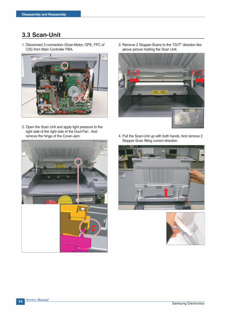
3.3 Scan-Unit
1. Disconnect 3 connectors (Scan-Motor, OPE, FFC ofCIS) from Main Controller PBA.
2. Open the Scan Unit and apply light pressure to theright side of the right side of the Duct-Fan . Andremove the hinge of the Cover-Jam.
3. Remove 2 Stopper-Scans to the “OUT” direction likeabove picture holding the Scan Unit.
4. Pull the Scan-Unit up with both hands. And remove 2Stopper-Scan fitting correct direction.
OUT OUT
Disassembly and Reassembly
Service Manual 3-7Samsung Electronics
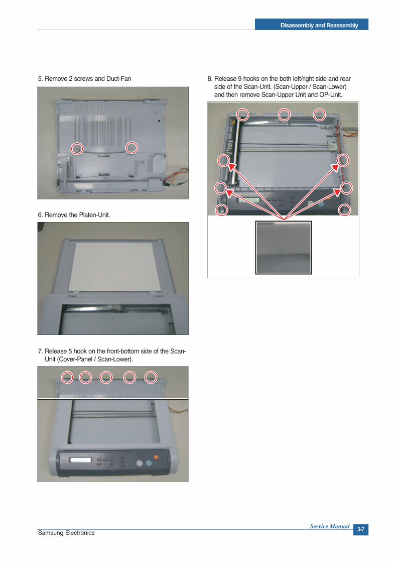
5. Remove 2 screws and Duct-Fan
6. Remove the Platen-Unit.
7. Release 5 hook on the front-bottom side of the Scan-Unit (Cover-Panel / Scan-Lower).
8. Release 9 hooks on the both left/right side and rearside of the Scan-Unit. (Scan-Upper / Scan-Lower)and then remove Scan-Upper Unit and OP-Unit.

Service Manual
Disassembly and Reassembly
3-8 Samsung Electronics
3.4 Cover-Middle Unit
1. Disconnect the connector of the Fan.
2. Disconnect 2 connectors. (USB Host & Joint PBA)
3. Remove 4 screws and Cover-Jam from the Cover-Middle Unit.
4. Remove Fan on the left side of the Cover Middle.
5. Remove 2 screws and Cap-USB and remove 1 screw/ USB Host PBA.
6. Remove Joint PBA.
Disassembly and Reassembly
Service Manual 3-9Samsung Electronics
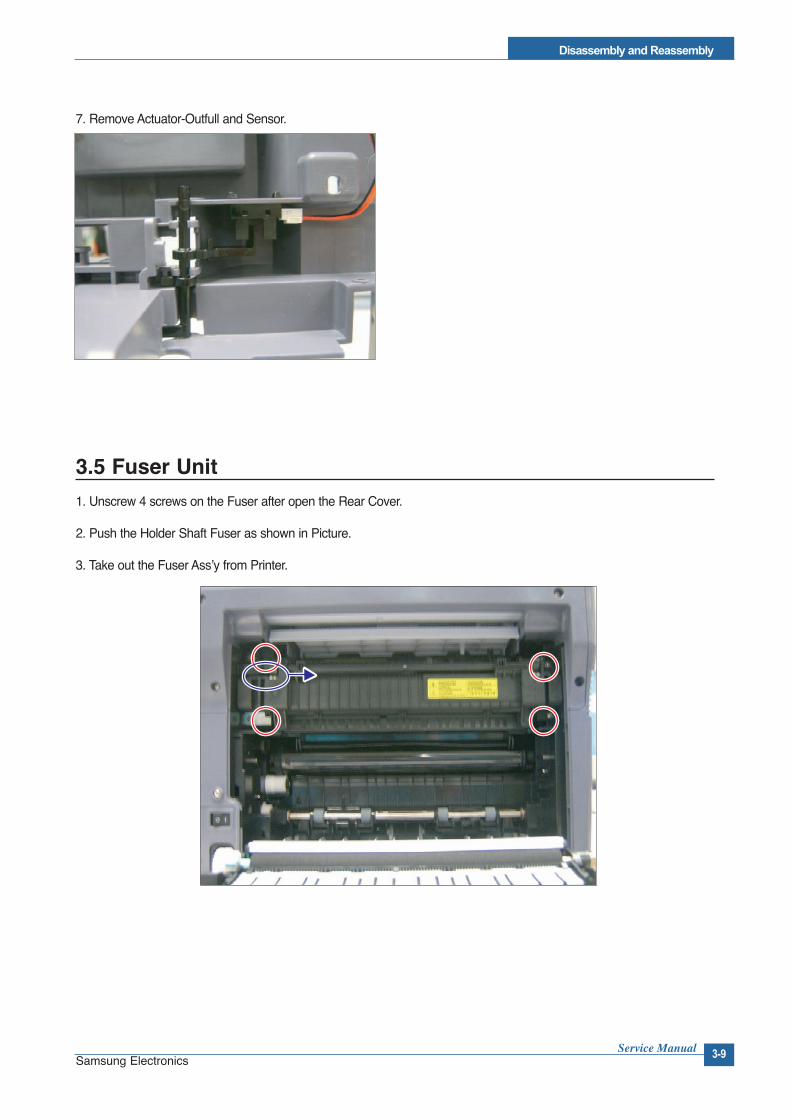
7. Remove Actuator-Outfull and Sensor.
3.5 Fuser Unit
1. Unscrew 4 screws on the Fuser after open the Rear Cover.
2. Push the Holder Shaft Fuser as shown in Picture.
3. Take out the Fuser Ass’y from Printer.

Service Manual
Disassembly and Reassembly
3-10 Samsung Electronics
3.6 LSU (Laser Scan Unit)
1. Follow step 1 in Cover Unit Disassembly
2. Lift up the LSU Cover (as shown in Picture) and then take out.
3. Remove 3 screws and then take out the LSU.
3.7 HVPS (High Voltage Power Supply)
1. Follow step 1 in Cover Unit Disassembly except removing Rear-Cover.
2. Unscrew 6 screws and disconnect then take out the HVPS.
Be careful of taking out the HVPS because there are 11 High Voltage Terminal behind HVPS.

Disassembly and Reassembly
Service Manual 3-11Samsung Electronics
3.8 Main Controller PBA
1. Follow step 1 in Cover Unit Disassembly
2. Unscrew 4 screws and then take out the Main Board after plug out all the Harness.
3.9 SMPS
1. Follow step 1 in Cover Unit Disassembly.
2. Remove the Main Board
3. Unscrew 4 screws and then take out the SMPS after plug out all the Harness.

Service Manual
Disassembly and Reassembly
3-12 Samsung Electronics
3.10 Drive Unit
1. Follow step 1 through step 4 in Cover Unit Disassembly.
2. Remove the Main Board.
3. Remove the SMPS.
4. Unscrew 8 screws and then take out the Drive Ass'y.
3.11 Transfer Roller
1. Open Rear Cover.
2. Unscrew 2 screws.
3. Pull back the hook, which holds the Roller, like below picture and remove the Transfer Roller.