2n helios ip - 2entry.com.au · remember the password well or put it down just in case. because if...
TRANSCRIPT


The 2N TELEKOMUNIKACE a.s. is a Czech manufacturer and supplier of telecommunicationsequipment.
The product family developed by 2N TELEKOMUNIKACE a.s. includes GSM gateways, privatebranch exchanges (PBX), and door and lift communicators. 2N TELEKOMUNIKACE a.s. hasbeen ranked among the Czech top companies for years and represented a symbol ofstability and prosperity on the telecommunications market for almost two decades. Atpresent, we export our products into over 120 countries worldwide and have exclusivedistributors on all continents.
2N is a registered trademark of 2N TELEKOMUNIKACE a.s. Any product and/or other®
names mentioned herein are registered trademarks and/or trademarks or brands protectedby law.
2N TELEKOMUNIKACE a.s. administers the FAQ database to help you quickly findinformation and to answer your questions about 2N products and services. Onwww.faq.2n.cz you can find information regarding products adjustment and instructions foroptimum use and procedures „What to do if...“.
2N TELEKOMUNIKACE a.s. hereby declares that the 2N product complies with all® Helios IPbasic requirements and other relevant provisions of the 1999/5/EC directive. For the fullwording of the Declaration of Conformity see the CD-ROM (if enclosed) or our website atwww.2n.cz.
This device complies with part 15 of the FCC Rules. Operation is subject to the followingtwo conditions: (1) This device may not cause harmful interference, and (2) this devicemust accept any interference received, including interference that may cause undesiredoperation.
The 2N TELEKOMUNIKACE a.s. is the holder of the ISO 9001:2009 certificate. Alldevelopment, production and distribution processes of the company are managed by thisstandard and guarantee a high quality, technical level and professional aspect of all ourproducts.
Content

Content 1. Product Overview . . . . . . . . . . . . . . . . . . . . . . . . . . . . . . . . . . 4
2. Express Wizard for Basic Settings . . . . . . . . . . . . . . . . . . . . 6
3. Model Differences and Function Licensing . . . . . . . . . . . . . 11
4. Signalling of Operational Statuses . . . . . . . . . . . . . . . . . . . . 14
5. Intercom Configuration . . . . . . . . . . . . . . . . . . . . . . . . . . . . . 16 5.1 Status . . . . . . . . . . . . . . . . . . . . . . . . . . . . . . . . . . . . . . . . . . . . . . . . . . . . . . . . . 19
5.2 Directory . . . . . . . . . . . . . . . . . . . . . . . . . . . . . . . . . . . . . . . . . . . . . . . . . . . . . . . 23 5.3 Hardware . . . . . . . . . . . . . . . . . . . . . . . . . . . . . . . . . . . . . . . . . . . . . . . . . . . . . . 36 5.4 Services . . . . . . . . . . . . . . . . . . . . . . . . . . . . . . . . . . . . . . . . . . . . . . . . . . . . . . . 70 5.5 System . . . . . . . . . . . . . . . . . . . . . . . . . . . . . . . . . . . . . . . . . . . . . . . . . . . . . . . . 109
6. Supplementary Information . . . . . . . . . . . . . . . . . . . . . . . . . . 125 6.1 Troubleshooting . . . . . . . . . . . . . . . . . . . . . . . . . . . . . . . . . . . . . . . . . . . . . . . . . 126
6.2 Directives, Laws and Regulations . . . . . . . . . . . . . . . . . . . . . . . . . . . . . . . . . . . 127 6.3 General Instructions and Cautions . . . . . . . . . . . . . . . . . . . . . . . . . . . . . . . . . . . 129

42N TELEKOMUNIKACE a.s., www.2n.cz®
1. Product Overview
The door intercoms can smartly replace traditional doorbell2N Helios IP®
push-button speakerphone panels and all wiring, bells and home intercom installationsin buildings with structured cabling. The intercoms provide more advanced and widerservices than standard home phones. The installation is very easy, all you need isconnect the intercom to the other LAN elements using a UTP cable and set necessaryparameters.
Thanks to the integrated SIP protocol, the intercom can make use of all VoIP services:call forwarding at absence (to another office, VoiceMail or a cellular phone) or calltransfer (from the secretary’s office to the required person, e.g.).
The intercoms are equipped with a programmable number of quick dial buttons forspeed calling to the users whose numbers are included in the intercom Users list. Eachof the quick dial buttons can be assigned up to three phone numbers, which can bedialled in parallel or sequentially. Thanks to an integrated time sheet it is possible toconfigure each of the buttons in such a way that the called party is always accessibleand/or calls to selected phone numbers can be barred off the working hours.
Some models are equipped with a numeric keypad, which can be used2N Helios IP®
as a code lock or a standard push-button phone.
The intercoms help LAN users scan the area in front of the camera via 2N Helios IP®
video streaming. Thanks to the full ONVIF support, the intercoms can become part ofthe Video Surveillance System in your facility .
The intercoms can be equipped with an RFID card reader for authorised2N Helios IP®
access control and thus become a key part of your surveillance or attendance controlsystems.
The intercom is equipped with a relay switch (and, optionally, other2N Helios IP®
relays and outputs), which controls the electric lock or other equipment connected tothe intercom. Its activation time and method can be programmed flexibly: it can beactivated by a code, automatically by a call, by pressing a button, and so on.
The following symbols and pictograms are used in the manual:

52N TELEKOMUNIKACE a.s., www.2n.cz®
Safety
abide by this information to prevent persons from injury.Always
Warning
abide by this information to prevent damage to the device.Always
Caution
Important information for system functionality.
Tip
Useful information for quick and efficient functionality.
Note
Routines or advice for efficient use of the device.

62N TELEKOMUNIKACE a.s., www.2n.cz®
2. Express Wizard for BasicSettings
LAN Connection SettingYou have to know the intercom configuration interface address to connect to the LANsuccessfully. Automatic IP address retrieval from the DHCP server is set by default inthe intercoms. Thus, if connected to a network in which a DHCP server2N Helios IP®
configured to assign IP addresses to all new devices is available, the intercom willobtain an IP address from the DHCP server. The intercom IP address can be found inthe DHCP server status (according to the MAC address given on the production plate),or will be communicated to you by the intercom voice function; refer to the InstallationManual of your intercom model.
If there is no DHCP server in your LAN, use the intercom buttons to set the static IPaddress mode, refer to the Installation Manual of your intercom model. Your intercomaddress will then be Use it for the first login and then change it if192.168.1.100.necessary.
Now enter the intercom IP address into your favourite browser. We recommend you touse the latest Chrome, Firefox or Internet Explorer 9+ versions as is2N Helios IP®
not fully compatible with earlier browser versions.
Use the name and password (i.e. default reset password) for your first loginadmin 2nto the configuration interface. We recommend you to change the default passwordupon your first login; refer to the parameter in the Password Services / Web Servermenu. Remember the password well or put it down just in case. Because if you forgetthe password, you will have to reset the intercom to default values (refer to theInstallation Manual of your intercom model) and lose all your current configurationchanges.
Tip
FAQ: IP address - How to get IP address of 2N® Helios IP

72N TELEKOMUNIKACE a.s., www.2n.cz®
Firmware UpdateWe also recommend you to update your intercom firmware upon the first login to theintercom. Refer to for the latest firmware version. Press the www.2n.cz Update
button in the menu to upload firmware. TheFirmware System Maintenance /intercom will get restarted upon upload and only then the updating process will becomplete. The process takes about 30 seconds.
SIP Server Connection SettingSet the following parameters in the menu to allow yourServices Phone SIP / / intercom make calls and be accessible within your VoIP infrastructure.
– set the name to be displayed as CLIP on the called party'sDisplay namephone, in the login window and on the web interface start page.
– set the intercom phone number (or another unique IDPhone number (ID)composed of characters and digits) to identify the intercom uniquely in calls andregistration.
– set the domain name of the service with which the intercom isDomainregistered. Typically, it is equivalent to the SIP Proxy or Registrar address. If youdo not use a SIP Proxy in your intercom installation, enter the intercom IPaddress.
If you use a SIP server (Proxy, Registrar), set the addresses for the following networkelements:

82N TELEKOMUNIKACE a.s., www.2n.cz®
– set the SIP Proxy IP address or domain name.Proxy address – set the SIP Registrar IP address or domain name. The SIPRegistrar address
Proxy and SIP Registrar addresses are usually identical. – enable intercom registration with the set SIP Registrar.Registration enabled
If your SIP server requires authentication of terminal equipment, enter the followingparameters:
– enter the password for intercom authentication.Password
Quick Dial Button SettingsAll the models are equipped with quick dial buttons. If you press a2N Helios IP®
quick dial button, a call will be set up to the phone number assigned to the respectiveUsers list position.
Select position 1, which corresponds to quick dial button 1, in the Directory Users/menu.
Enable the position in the field and enter the called station phonePosition Enabled number into the parameter in the section.Phone Number User Phone Numbers

92N TELEKOMUNIKACE a.s., www.2n.cz®
You can also use the intercom with one or more IP phones without a2N Helios IP®
SIP server. Use the for outgoing calls and enter the called phone SIPDirect SIP Calladdress ( ) instead of the phone number.sip:phone_number@phone_ip_address
Electric Lock Switching SettingsAn electric lock can be attached to the intercoms and controlled by a2N Helios IP®
code from the intercom numeric keypad, or a code from the IP phone keypad during acall. Connect the electric lock as instructed in the Installation Manual of your intercommodel.

102N TELEKOMUNIKACE a.s., www.2n.cz®
Enable the switch in the parameter in the Switch Enabled Hardware Switches / / tab, set the to the intercom output to which the electric Switch 1 Controlled Output
door lock is connected. Now set one or more activation codes for the electric door lockswitching.

112N TELEKOMUNIKACE a.s., www.2n.cz®
3. Model Differences andFunction Licensing
This manual is valid for all members of the family and so some features2N Helios IP ®
described herein are only available in selected models or need to be2N Helios IP ®
activated with a valid licence key. This section provides a short list of differencesbetween the models and licences which affect the configuration options. If a function isnot available in all the models, there is a note in the respective subsection andreference to this section.
The table below includes an overview of properties and functions of all the 2N Helios®
models.IP
Property/Model
2N Helios IP®
Verso Vario Force Safety Uni AudioKit
VideoKit
Part No. 9155… 9137…. 9151… 9152… 9153… 9154… 9154…C
Integrated camera optional ne
Camera resolution 1280 x960 640 x 480
External analoguecamera support no yes
External IP camerasupport yes no yes
Internal RFID cardreader optional no
Display no optional no

122N TELEKOMUNIKACE a.s., www.2n.cz®
Property/Model
2N Helios IP®
Verso Vario Force Safety Uni AudioKit
VideoKit
Basic unit button count 1 1, 3or 6
1, 2or 4 1 1 or
2up to 16external
programmablebuttons
Button extenders up to145
up to48 no
Numeric keypad optional no
Digital input yes optional no 2
Wideband audio codecs (L16,G.722) yes no yes
Amplifier power output 2 W 150 mW 1 W 10 W
Extended amplifier poweroutput (10 W) no yes no no
Tamper switch optional no optional yes no
Users position count 1999 2 16
User deputy yes no yes
User activation/deactivation yes no yes
Controlled switch count 4 1 4
Switch universal code count 10 2 10
User profile count20
JPEG HTTP video yes no yes
2N Helios IP Eye® support yes no yes
Telephone mode yes no yes
Some functions are unavailable until a valid licence key is entered2N Helios IP®
(refer to the Licence subsection). The following types of licences are available:
Enhanced Audio (Part No. 9137905)Enhanced Video (Part No. 9137906)Enhanced Integration (Part No. 9137907)Enhanced Security (Part No. 9137908)Gold (Part No. 9137909)G.729 (Part No. 9137902)InformaCast (Part No. 9137910)NFC (Part No. 9137915)
The G.729 licence allows the audio codec G.729 to be used.
The InformaCast licence allows the SingleWire InformaCast protocol to be used.
The NFC licence enables authentication via NFC-equipped mobile phones for selected13Mhz RFID card reader models.
No licenced features are available for the model.2N Helios IP Uni @
The table below includes the functions that need to be activated by the licence keys

132N TELEKOMUNIKACE a.s., www.2n.cz®
corresponding to the above mentioned licences. The licences can be combinedarbitrarily.
Property/Licence EnhancedAudio
EnhancedVideo
EnhancedIntegration
EnhancedSecurity NFC Gold
(Profi)User sounds • •
Automatic audiotest • •
Noise detection • •Audio/videostreaming (RTSPServer)
• •
External IP camerasupport • •
ONVIF support • •
PTZ functionsupport • •
Motion detectionsupport • •
Extended switchsetting options • •
HTTP API (see notebelow) • •
Automationfunctions • •
E-mail sending(SMTP Client) • •
Automatic update(TFTP/HTTP Client) • •
FTP client • •SNMP client • •802.1x support • •
SIPS (TLS) support • •
NFC support • •
Note
Full HTTP API function is available with the Gold or Enhanced Integrationlicence only. Only Camera API a Switch API is available without thislicence.
Note
Extended switch setting options – switch activation by call; switchactivation with quick dial button; time profile for switch
Tip
FAQ: License for 2N Helios IP - How to get it®

142N TELEKOMUNIKACE a.s., www.2n.cz®
4. Signalling of OperationalStatuses
2N Helios IP® generates sounds to signal switching and changes of operationalstatuses. Each status change is assigned a different type of tone. See the table belowfor the list of signals.
Tone MeaningUser activatedThis tone signals entering of the user activation code. The activation code is used for user (user's position) . Referactivationto the Users subsection for the activation code settings.
User deactivatedThis tone signals entering of the user deactivation code. Thedeactivation code is used for user (user's position) deactivation.A deactivated user may not be called but the call can, ifnecessary, be forwarded to a deputy if defined. Refer to the
.Users subsection for the deactivation code settings
Profile activatedThis tone signals profile . This function helps enableactivationalerting of a user group in an office, for example. Refer to the
.Profile subsection for the activation code settings
Profile deactivatedThis tone signals profile deactivation. This function helps, forexample, disable alerting of a user group in an office and routingcalls either to a pre-defined phone number (porter's lodge, e.g.)or user mobile phones. Refer to the Profile subsection for the
.deactivation code settings
Note
Signalling of some of the above mentioned statuses can be modified; referto the User Sounds subsection.

152N TELEKOMUNIKACE a.s., www.2n.cz®
Call prolongation confirmation signallingCalls are time-limited in for security reasons2N Helios IP®
(protection against blocking). Refer to the Miscellaneous.subsection for details
Internal application launchedThe internal application is launched upon power 2N Helios IP ®
up or restart. A successful launch is signalled by this tonecombination.
Connected to LAN, IP address received2N Helios IP® logs in upon the internal application launch. A
.successful LAN login is signalled by this tone combination
Disconnected from LAN, IP address lostThis tone signals UTP cable disconnection from .2N Helios IP®
Disconnection .is signalled by this tone combination
Invalid telephone number or invalid switch activation code2N Helios IP® allows the user to dial an extension numberdirectly using the keypad or enter the door unlocking code. Aninvalid code is signalled by this tone sequence.
Default reset of network parametersUpon power up, a 30 s timeout is set for the default reset codeentering. Refer to the Device Configuration subsection in the 2N
Installation Manual for details. Helios IP ®
Call end signalling2N Helios IP® enables the user to set a call end timeout toavoid call blocking. Press a key on your VoIP phone to extend thecall time during this timeout.
Connected VoIP phone – 2N Helios IP call®
This short tone signals successful connection between a VoIPphone and .2N Helios IP®


172N TELEKOMUNIKACE a.s., www.2n.cz®
Start ScreenThe start screen is an introductory overview screen displayed upon login to the
intercom web interface. Use the back arrow in the left-hand upper corner of thefollowing web interface pages to return to this screen anytime.
The screen header includes the intercom name (refer to the parameterDisplay Namein the menu). Select the web interface language with the Services / Phone SIP / CZand buttons. Press the button in the right-hand upper corner to log out.EN Log out
The start screen is also the first menu level and quick navigation (click on a tile) toselected intercom configuration sections. Some tiles also display the state of selectedservices.
Configuration MenuThe configuration includes 5 main menus: 2N Helios IP® State, Directory,
and including submenus; see below.Hardware, Services System
Status
Device – essentials on the intercom Services – information on active services and their statesLicence – current states of licences and available intercom functions
Directory
Users – settings for user phone numbers, quick dial buttons, access cards and switch control user codesTime Profiles – time profile settings Access Cards – access card settings
Hardware
Switches – electric lock, lighting, etc. settings Audio – audio, signalling, etc. volume control, microphone parameters Camera – internal camera, external IP camera settingsKeyboard – button and keyboard settings Buttons - user speed dial settingsDisplay – basic display settingsCard Reader – card reader, Wiegand interface settings Extenders – extender settings 2N Helios IP Verso ®
Tip
Video Tutorial: New web interface of 2N Helios IP intercoms®

182N TELEKOMUNIKACE a.s., www.2n.cz®
Services
Phone – telephone and SIP connection settings Streaming – audio/video streaming settings (ONVIF, RTSP, Multicast, etc.) Onvif - Onvif settingsE-Mail – E-mail sending and SMTP connection settings Automation – flexible intercom settings according to the user's requirementsHTTP API - HTTP API authorisation settingsUser Sounds – user sound settings and upload Web Server – web server and access password settings Audio Test – automatic audio test settings SNMP - SNMP settings
System
Network – LAN connection settings, 802.1x, packet capturing Date and Time – real time and time zone settings Licence – licence settings, trial licence activation Certificates – certificate and private key settings Auto provisioning – automatic firmware and configuration update settings Syslog – syslog message sending settings Maintenance – backup and configuration reset, firmware update

192N TELEKOMUNIKACE a.s., www.2n.cz®
5.1 Status
The menu provides clear status and other essential information on theStatusintercom. The menu is divided into three tabs: , and .Device Services Licence
DeviceThe tab displays basic information on the intercom model, its features,Devicefirmware and bootloader versions and so on.
ServicesThe tab displays the status of the network interface and selected services.Services

202N TELEKOMUNIKACE a.s., www.2n.cz®
LicenceThe tab displays the list of licensed functions of the intercom including their Licencecurrent availability (on the basis of a valid licence key entered in the System |
menu).Licence

212N TELEKOMUNIKACE a.s., www.2n.cz®
Access LogThe tab displays the last 10 records on applied cards. Each record includesAccess Log the card tapping time, card ID and type and description details (validity, card owner,etc.).


232N TELEKOMUNIKACE a.s., www.2n.cz®
5.2 DirectoryHere is what you can find in this subsection:
5.2.1 Users5.2.2 Time Profiles5.2.3 Access Cards

242N TELEKOMUNIKACE a.s., www.2n.cz®
5.2.1 Users
The Users list is one of the crucial parts of the intercom configuration. It contains userinformation relevant for such intercom functions as quick dialling, RFID card/code doorunlocking, missed call e-mails and so on.
The Users list contains up to 1999 users (variable in the models) –2N® Helios IPtypically, each user is assigned just one item (position 1 to 1999).
The Users list includes the users that can be called via the quick dial buttons and theusers that are assigned the RFID card, code, etc. access to the building.
Use the menu to assign the quick dial users. By default, buttonHardware / Buttons 1 is assigned to position 1 in the user list, button 2 to position 2 in the phone book,etc. You can change the user and button settings as necessary. Most of the 2N®
intercoms are equipped with one or more quick dial buttons. Refer to theHelios IP Installation Manual of your intercom model for the quick dial button count andextending options.
Every record in the Users list includes the following parameters:
– a mandatory parameter for easier user search, for example.Name – user e-mail address for sending missed call information.E-mail
– number to be used for user calling via a numeric keypad.Virtual numberVirtual numbers are not associated with user telephone numbers. They areincluded in an independent numbering plan allowing you to withhold usertelephone numbers, especially in installations where the quick dial button count isinsufficient. The visitor enters a virtual number via the numerical keypad andpresses the * key. You are recommended to place a clear user/virtual number listnearby including simple instructions for use to facilitate this type of user calls.Enable this function in the in the Dial by Numeric Keypad Hardware /
menu. The following options are available: –Keyboard User phone numbersenter up to three user numbers to be called sequentially in predefined timeintervals or at the same time (group calls). You can assign a time profile and theaddress of the PC on which the application is running to2N® Helios IP Eyedisplay the intercom camera image before call answering, for example.
Disabled – no user number can be entered via the numeric keypad. – enter the user virtual number via the numericUser virtual number
keypad and press * to start the call. – enter the user position (01 – 1999) via theUser position number

252N TELEKOMUNIKACE a.s., www.2n.cz®
numeric keypad and press * to start the call. This original FW 2.10 option isno more recommended due to potential user management troubles.
– enter the switch activating user codes (door lockUser switch codesactivation, e.g.). A time profile can be assigned to each code.
– enter the user-defined access cards with/without a time profile.User cardsEnable/disable double authentication (valid user card + switch activating code)for each user.
– enter the user-defined codes toUser activation and deactivation codesactivate/deactivate speed dial and virtual number calling. Calls to a deactivateduser are automatically forwarded to the User deputy.
Refer to the menu for the Users settings. Use the navigation panelDirectory / Users for selecting the user positions easily and arrows for scrolling pages. Or, you can enter
the position number and push to move to the position quickly. If you know the
user's name, push to find its position.
List of Parameters
Position enabled – enable calling to this user position.
Name – enter the user name for the selected user position. This parameter isoptional and helps you find items in the user list more easily.E-mail – enter the user E-mail to which information on missed or successful callscan be sent. Refer to the E-Mail subsection for more details.Virtual Number - number to be used for user calling via a numerickeypad. Enable this function in the in the Dial by Numeric Keypad Hardware
menu./ Keyboard

262N TELEKOMUNIKACE a.s., www.2n.cz®
You can assign up to three user phone numbers to each user position. In case the useris inaccessible on one number, the following number will be dialled after a ringingtimeout. Enable the to enable dialling multipleParallel call to following numbernumbers simultaneously. The phone number validity can also be time profile-limited.
Phone number – enter the phone number of the station to which the call shallbe routed. Enter the address sip:[user_id@]domain[:port] for Direct SIP calling,e.g.: sip:[email protected] or .sip:name@yourcompanyEnter device:device_name for calls to the application. Set2N Helios IP Mobile®
the device name in the mobile application. Enter or behind the phone/1 /2number to specify which SIP account shall be used for outgoing calls (account 1or 2).Time profile – assign a time profile to each phone number to define the numbervalidity. If the profile in inactive, the phone number is not used and the followingphone number is dialled if defined.Helios IP Eye address – set the address of the PC to be sent a special UDPmessage on each active user phone number call. With the aid of this message,the application displays the camera image screen for those2N Helios Eye®
users who are not provided with a display-equipped videophone. Enter theaddress as follows: ip_address[: ][: ]. The and port1 port2 port1 port2 parameters are optional and are used in case there is Network Address

272N TELEKOMUNIKACE a.s., www.2n.cz®
Translation (NAT) between the PC and intercom and the addresses have tocomply with the router or another NAT-executing device. The port1 (defaultvalue: 8003) parameter defines the destination port for the UDP messages sentto . The port2 (default value: 80) parameter defines the2N Helios IP Eye®
destination port for the – intercom HTTP communication.2N Helios IP Eye®
Parallel call to following number – enable group calling, i.e. calling to morephone numbers at the same time. You can call the first two numbers, the lasttwo numbers, or all of the three user numbers in parallel. Answering one callautomatically terminates the other calls.Parallel call to following deputy – extend group calling to include the Userdeputy.User deputy – select a user to which the user calls will be routed in the event ofinaccessibility. Enter user position number or use search button. The deputy setting is applied when the user fails to answer the call to any of its phonenumbers within the predefined timeout, or if the user numbers are inaccessiblefor other reasons (time profiles, user deactivation).
Each intercom user can be assigned its activation/deactivation code for call routingpurposes. If a user is deactivated, calls are routed not to its phone numbers but to thepredefined user deputy at inaccessibility.
User activation code – set a private user activation code: up to 16 charactersincluding digits 0-9 only. If the user activation code is the only code defined orthe activation and deactivation codes are identical, the activation code is used
Note
The 'Helios IP Eye Address' function is available in selected 2N Helios®
models only (refer to the model and licence overview).IP
Tip
FAQ: 2N Helios IP Eye - How to set®
Tip
Video Tutorial: SW application for IP intercoms - 2N Helios IP Eye®
Note
The User Deputy function is available in selected 2N Helios IP® models).only (refer to the model and licence overview

282N TELEKOMUNIKACE a.s., www.2n.cz®
both for user activation and deactivation.User deactivation code – set a private user deactivation code: up to 16characters including digits 0-9 only.User current state – select the current state of the user.
Each user can be assigned a private switch activation code. The user switch codes canbe arbitrarily combined with the universal switch codes defined in the Hardware |
menu. If the codes are identical with the codes already defined in theSwitches intercom configuration, the mark will appear at the colliding codes.
Code – set a private user switch activation code: up to 16 characters including digits0–9 only.
Time profile – assign a time profile to the switch code to define the codevalidity. If the time profile is inactive, the switch will not be activated by the code. If multiple time profiles are assigned to a code, the code is valid only if one ofthe profiles is active at least.
Each of the intercom users can be assigned one access RFID card. Refer to the Accesssubsection for details.Cards
Card ID – set the user access card ID: 6–32 characters including 0–9, A–F. Eachuser can be assigned just one access card. When a valid card is tapped on thereader, the switch associated with the card reader gets activated. If the doubleauthentication mode is enabled, the switch can only be activated using both acard and numeric code.Time profile – assign a time profile to the user access card to define the cardvalidity. If the time profile is inactive, the user access card will be detected asinvalid. If multiple time profiles are assigned to a card, the card is valid only if

292N TELEKOMUNIKACE a.s., www.2n.cz®
one of the profiles is active at least.Double authentication - set card + numeric code authentication for a user:apply a valid user card and then enter one of the switch activating codes (withinten seconds after tapping) to activate the switch in this mode.

302N TELEKOMUNIKACE a.s., www.2n.cz®
5.2.2 Time Profiles
Such intercom functions as outgoing calls and RFID card/numeric code access, forexample, can be time-limited by being assigned a . By assigning a timetime profileprofile you can:
block all calls to a selected user beyond the set time intervalblock calls to selected phone numbers beyond the set time intervalblock RFID access for a user beyond the set time intervalblock numeric code access for a user beyond the set time intervalblock switch activation beyond the set time interval
Assign a time profile according to a week time sheet to define availability of theselected function. Just set from-to or days in the week on which the function shall beavailable. helps you create up to 20 time profiles (depending on the 2N Helios IP® 2N
model) that can be assigned to the function; refer to the Users, Access Helios IP®
Cards and Switches settings.
The time profiles are defined not only using the week time sheet but also manually withthe aid of special activation/deactivation codes that you can assign to them afterarriving in/before leaving your office, for example. Enter the activation/deactivationcodes using the numeric keypad of your intercom or phone (during the intercom call).Refer to the / menu for the time profile settings.Directory Time Profiles
Caution
In case you use the 2N ® Manager for intercom configuration,Helios IPwe do not recommend you to modify the time profile settings via the webinterface.

312N TELEKOMUNIKACE a.s., www.2n.cz®
List of Parameters
Profile name – enter a profile name. This parameter is optional and helps youfind items in the time profile list and select profiles in the switch, card and phonenumber settings more easily.
This parameter helps you set time profiles within a week period. A profile is activewhen it matches the set intervals. Make sure that the real time settings are correct(refer to the Date and Time subsection) to make this function work properly.
If the profile activation/deactivation code is not defined, the profile state is based onthe time sheet exclusively.
If you apply a time profile together with the activation/deactivation code, the profilewill be active only if the time condition is met and the profile is code-activated at thesame time.
Note
Check off a day and set the From/To fields to 00:00 to make a time profileactive the whole day.

322N TELEKOMUNIKACE a.s., www.2n.cz®
Profile activation code – set the profile activation code: 16 charactersincluding digits 0–9 only. If the activation code is the only code defined or theactivation and deactivation codes are identical, then the activation code is usedboth for profile activation and deactivation.Profile deactivation code – set the profile deactivation code: 16 charactersincluding digits 0–9 only.Profile current state – select the current state of the user.

332N TELEKOMUNIKACE a.s., www.2n.cz®
5.2.3 Access Cards
Each intercom user can be assigned one or more access RFID cards. Typically, the cardID is included in the users list together with such user data as phone numbers, E-mailaddress and so on. Or, you can define the RFID cards in the Installed Cards list, whichdefines a limited number of unassigned cards reserved for visitors, for example.
You can manage – add, remove and modify items – the list of installed cards manuallyvia the intercom configuration interface. The main advantage of this list is the option toadd/remove using the Service plus/minus cards without accessing the configurationinterface. Unlike the users list with its up to 1999 positions, the Installed Cards maycontain only 20 cards.
To add a card to the list, apply the plus card and then tap the card to be added on thereader. The RFID card will be added if the list in not full and does not include the cardyet. To remove a card from the list, apply the minus card and then tap the card to beremoved on the reader. The RFID card record will be cancelled and access via this cardwill be blocked.
Service cards help you add/remove cards to/from the list. Enter their IDs in the PlusCard ID and Minus Card ID fields in the : 6–32 characters including 0–9,Service CardsA–F (i.e. hexadecimal number of the length of 24 to 128 bits). The number ofcharacters in the card ID can be different in different card types. However, it holds truethat cards of one and the same type have identically long IDs.
If your external card reader is connected to the intercom via the Wiegand interface, thecard ID is shortened to 6 or 8 characters for transmission (depending on thetransmission parameters). If you apply a card to the reader, you will receive acomplete ID, which is typically longer (8 chars or more). The last 6 or 8 characters,however, are identical. This is useful for comparing card IDs with the intercomdatabase: if the IDs to be compared have different lengths, they are compared fromthe end and match has to be found in 6 characters at least. If they have identicallengths, all the characters are compared. This ensures mutual compatibility of theinternal and external readers. Go to the menuDirectory / Access Cards Records/to identify whether the card was tapped on the internal or external reader.
All cards applied via the reader or the Wiegand interface are recorded. Refer to the menu for the last 10 cards including the card ID/type, cardStatus Access Log/
tapping time and other information if necessary. With small systems, you can make a

342N TELEKOMUNIKACE a.s., www.2n.cz®
trick to enter card IDs: tap the card on the intercom reader and find it in the Access. Double-click to select the card ID and push CTRL+C. Now that you have the cardLog
ID in your box, you can insert it with CTRL+V in any intercom setting field.
Having been read, the card ID is compared with the intercom card database. If thecard ID matches any of the cards in the database, the appropriate action will beexecuted: switch activation (door unlocking, etc.). To change the switch number to beactivated, use the parameter in the mAssociated Switch Hardware Card Reader/enu ( models) or the parame2N Helios IP Vario, Force, Safety ® Associated Switchter in the menu of the card reader module (Hardware Modules/ 2N Helios IP®
model).Verso Refer to the menu for the access card settings.Directory Access Cards /
List of Parameters
Cards
Plus card ID – enter the service card ID for adding cards to the Installed cards:a sequence of 6–32 characters including 0–9, A–F.Minus card ID – enter the service card ID for removing cards from the Installedcards: a sequence of 6–32 characters including 0–9, A–F.
Card ID – enter the access card ID: a sequence of 6–32 characters including0–9, A–F.Time profile – assign a time profile to the user access card to define the cardvalidity. If the time profile is inactive, the user access card will be detected asinvalid.Description – enter such information as the card owner name and similar. The

352N TELEKOMUNIKACE a.s., www.2n.cz®
description gets displayed in the menu whenever the card is appliedRecordsand helps you find the card list items more easily without affecting the intercomfunction.

362N TELEKOMUNIKACE a.s., www.2n.cz®
5.3 HardwareHere is what you can find in this section:
5.3.1 Switches5.3.2 Audio5.3.3 Camera5.3.4 Keyboard5.3.5 Buttons5.3.6 Display5.3.7 Card Reader5.3.8 Digital Inputs5.3.9 Extenders

372N TELEKOMUNIKACE a.s., www.2n.cz®
5.3.1 Switches
Switches provide a very flexible and efficient control of such intercom peripherals aselectric door locks, lighting, additional ringing signalling, and so on. allo2N Helios IP®
ws you to configure up to 4 (depending on model types) independent all-purposeswitches. A switch can be activated:
by entering the valid code via the intercom numeric keypad or receiving a DTMFsequence during a call.by tapping a valid RFID card on the reader.with a predefined delay after another switch activation.by an incoming or outgoing call 1).by pressing a quick dial button 1).by receiving the HTTP command from another LAN device 1).via Automation using the Action.ActivateSwitch action.
Switch activation can be blocked by an appropriately selected time profile if necessary. If a switch is active, you can:
activate any logical output of the intercom (relay, power output).activate the output to which the Security Relay module is2N Helios IP®
connected.send an HTTP command to another device.
The switch can work in the monostable or bistable mode. The switch is switched offafter a timeout in the monostable mode, and switched on with the first activation andoff with the next activation in the bistable mode.The switch signals its state:
by a programmable beep or a predefined user sound.by a LED indicator if available in the intercom model.by an open-door icon on the display if available in the intercom model.

382N TELEKOMUNIKACE a.s., www.2n.cz®
List of Parameters
Switch enabled – enable/disable the switch globally. When disabled, the switchcannot be activated by any of the available codes (including user switch codes),by a call or quick dial button.
Switch mode – set the monostable/bistable mode for the switch. The switch is switched off after a timeout in the monostable mode, and switched on with thefirst activation and off with the next activation in the bistable mode.Switch-on duration – set the switch-on time for a monostable switch. This value is not applied in the bistable mode.Time profile – assign the switch a time profile to enable switch-on. If the time profile is inactive, the switch cannot be activated by a code, call or quick dialbutton.Distinguish on/off codes - set a switch code mode in which odd codes (1, 3....) are used for switch activation and even codes (2, 4 ...) are for switchdeactivation. This mode can only be used if the switch is set to the bistablemode.
Controlled output – assign an electric output to the switch. Choose one of the available intercom outputs: relay, power output, extender output. If you select
, the switch will not control any electric output but can control externalNoneequipment via HTTP commands.
Note
Switch time profiles are available with the Gold or Enhanced Integrationlicence only.

392N TELEKOMUNIKACE a.s., www.2n.cz®
Output type – if you use the Security Relay module, set the 2N Helios IP ®
output type to . In the mode, the output works in the inverseSecurity Securitymode, i.e. remains closed and controls the Security Relay module 2N Helios IP ®
using a specific pulse sequence.
The table above includes a list of universal codes that help you activate switches fromthe phone or intercom keypad. Up to 10 universal codes can be defined for each switch(depending on the particular intercom model).
Code – enter a numeric code for the switch. The code must include 2 charactersat least but we recommend you to use four characters at least to make the codeaccessible from the intercom numeric keypad. Codes 00 and 11 can't be enteredfrom numeric keypad. Code is confirmed with *. Code length up to 16characters. Accessibility – block the switch activation code entering from the intercomnumeric keypad or your phone.Time profile – assign a time profile to the switch code to control its validity.
Activation by call – enable switch activation by an incoming or outgoing call,
Note
2N® – be sure to set the internal power supply andHelios IP Varioswitching relay on the configuration connector.2N® – the security relay is connected to the DOOR +Helios IP Forceand - terminals.
Note
The extended switch activation is available with the Gold or Enhanced Integration licence only.

402N TELEKOMUNIKACE a.s., www.2n.cz®
for example. During an outgoing call the switch is activated after SIP message180 Ringing is received. The called party confirms ringing by this message. Theswitch is active during the whole call in the bistable mode, and activated by thecall beginning and deactivated after the predefined switch-on duration in themonostable mode.Activation by quick dial button – assign a quick dial button to the switch. Theswitch is activated whenever the button is pressed.
Sound signalling – set the sound signalling type for switch activation. Choosethe Short beep, Long beep (during the whole activation) or a User sound (refer tothe User Sounds subsection).Display info – enable/disable signalling of an activated switch on the display.
Synchronise with – set switch synchronisation to enable automatic switchactivation after another switch activation with a predefined delay. Define thedelay in the parameterSynchronisation delay Synchronisation delay – set the time interval between synchronised activationsof two switches. The parameter will not be applied if the function isSynchronise disabled.
Command sent upon activation – set the command to be sent to the externaldevice (WEB relay, e.g.) upon switch activation. The command is sent via the
Note
The HTTP command sending is available with the Gold or Enhanced Integration licence only .

412N TELEKOMUNIKACE a.s., www.2n.cz®
HTTP (GET request) and must be as follows: http://ip_address/path. E.g.: .http://192.168.1.50/relay1=on
Command sent upon deactivation – set the command to be sent to theexternal device (WEB relay, e.g.) upon switch deactivation. The command is sentvia the HTTP (GET request) and must be as follows: http://ip_address/path.E.g.: http://192.168.1.50/relay1=off
Legacy switch code – enable the option to activate the first-listed switch When this box is checked,code from the phone without being confirmed with *.
first code does not require confirmation by *. This setting does not apply to otherswitch codes listed and to numeric keypad code activation, those must be alwaysconfirmed by *. The Legacy switch code helps you keep back compatibility withearlier 2N intercom models.
Note
The switch time profiles are available with the Gold or Enhanced Integration licence only.

422N TELEKOMUNIKACE a.s., www.2n.cz®
5.3.2 Audio
All the models are equipped with a speaker or power amplifier output2N Helios IP®
to which an external loudspeaker can be connected. Set the phone call and statesignalling volume control in this configuration section. Set the toMaster volume
e of calls, signalling tones, etc. Set thiscontrol the master volume of the device: volumparameter according to the ambient noise level. If the noise level is not constant, usethe Adaptive mode to increase the master volume temporarily depending on theambient noise level.
Model Master VolumeVario −12 db .. +0 dB (150mW)
Force/Safety 1W −12 dB .. +6 dB (1W)
Force/Safety 10W −12 dB .. +20 dB (10W)
Uni −16 dB .. +2 dB (1W)
Verso −8 dB .. +8 dB (2W)
Audio/Video Kit -10 dB .. +10 dBSIP Speaker -10 dB .. + 10 dB
List of Parameters
Master volume – set the master volume for the entire system. This settingaffects the volume of phone calls and all signalling tones.

432N TELEKOMUNIKACE a.s., www.2n.cz®
Adaptive volume – enable the adaptive volume mode in which the speakervolume is adjusted automatically depending on the noise level of the intercominstallation site.
– set the maximum gain to be applied to the master volume inMaximum gainthe adaptive mode.
– set the ambient noise threshold at which adaptive gainSensitivity thresholdis applied.
- display the current ambient noise level.Current noise level - display the current adaptive gain of the masterCurrent adaptive gain
volume. The value is determined by the difference of the Current noise level andSensitivity threshold and never exceeds the Maximum gain value.
Ringtone volume – set the incoming call signal loudness.Call-progress tone volume – set the dial, ring and busy tone volume. In casethe call-progress tones are automatically generated by the PBX, this setting willnot be applied.
Key beep volume – set the key beep volume. The volume values are relativeagainst the set master volume.Warning tone volume – set the volume of warning and signalling tonesdescribed in the section. The volumeSignalling of Operational Statuses

442N TELEKOMUNIKACE a.s., www.2n.cz®
values are relative against the set master volume.Switch activation tone volume – set the volume of the switch activation tone.The volume values are relative against the set master volume.User sounds volume - set the volume of the user sounds to be played. Thevolume values are relative against the set master volume.
– set the default audio input (microphone, line input orDefault audio inputaudio module input) to be used for phone calls and audio streaming.
- set the microphone input gain. Microphone input gain - set the line input gain independently of the microphone gainLine input gain
value.
Acoustic feedback filter - set automatic suppression of acoustic feedback(typically whistling) between the intercom speaker and phone handset if locatedin close proximity to the intercom. This mode is disabled by default.
Switch on automatic detection of noise or microphone noise level thresholdexceeding. Process the threshold exceeding alarm using anEvent.NoiseDetectedd assign it to other user actions.
TipThe microphone/line input gain setting is connected with the inputsignal level and type of external microphone installation. The widegain range (0 to 39dB for a microphone input and -6dB to 24dB fora line input) should be sufficient for most installations. Set a valueto ensure good audibility and eliminate excessive acoustic feedbackat high loudspeaker volumes with subsequent signal saturation onthe microphone/line input and thus acoustic echo cancellation (AEC)deterioration.

452N TELEKOMUNIKACE a.s., www.2n.cz®
Noise level threshold - set the microphone noise level threshold for alarmsetting.
- set the time interval during which the signal must be aboveAlarm start delaythe threshold to start alarm.
- set the time interval during which the signal must be belowAlarm end delaythe threshold to stop alarm.
- display the signal level history. Red designates alarmNoise level graphactivation.

462N TELEKOMUNIKACE a.s., www.2n.cz®
5.3.3 Camera
This menu is only available in the models that are equipped with an2N Helios IP ®
internal camera or can be connected to an external camera. The camera signal can bestreamed directly into the call via a videophone, sent by E-mail, streamed viaONVIF/RTSP to another device (a video surveillance device, e.g.), or simply HTTPdownloaded from the intercom in the JPEG format.
The following video signal sources can be used:
an internal integrated camera or external analogue camera (2N Helios IP®
only)Video Kit a standard external IP camera supporting RTSP stream with codecs MJPEG(640x480 max resolution) or H.264 (640x480 Base Line Profile max resolution).The recommended framerate is 15 frames per second in either case. Higherframe rates may result in undesired effects (less smooth playing).
The menu helps you set such camera parameters as brightness, colourCamerasaturation and external IP camera login data if necessary. Refer to the Services
and menus for the video/ Phone, Services Streaming / Services E-Mail /call/streaming parameters.
List of Parameters
Common Settings
Default video source – set the default video signal source. Choose Internalcamera (or an analogue camera connected to the intercom) or External IP

472N TELEKOMUNIKACE a.s., www.2n.cz®
camera.PTZ control enabled – enable the PTZ (Pan-Tilt-Zoom) function to control thecamera display area during the call via DTMF (for 2N® Helios IP Verso only) fromyour IP phone numeric keypad. Click the * key to enable/disable the PTZ mode.The meanings of the IP phone keys in the PTZ mode are as follows:
IP phone key PTZ mode function* Enable/disable PTZ1 Zoom in3 Zoom out2 Move cropped display up4 Move cropped display to the left6 Move cropped display to the right8 Move cropped display down5 Return to initial state
Internal Camera
Brightness level – set the camera image brightness level.Colour saturation – set the camera image colour saturation.Camera mode – select suitable camera modes according to the current intercominstallation conditions (indoor/outdoor use). Choose variable image flickercancellation modes for indoor sites illuminated by artificial light. Or, set directsunshine suppression for outdoor applications.Automatic framerate decreasing – enable automatic frame rate decreasingunder worsened illumination conditions to improve image quality by lowering theframe rate.Image trimming – the camera view angle allows you to2N Helios IP Force®
scan the largest area possible. Use this parameter to enable automatic cameraimage trimming to eliminate the (sometimes annoying) view of the intercomframe. Disable this function to get the maximum possible view angle. Theparameter is available in the models only.2N Helios IP Force ®
Day/Night mode - set the camera day/night mode. The options are automatic(controlled by the ambient light level), or permanently day or night mode. Current mode - display the currently selected camera mode (day/night). in theday mode, the camera uses an IR suppressing filter and infrared illumination isdisabled. In the night mode, the IR suppressing filter is disabled and infraredillumination is on.

482N TELEKOMUNIKACE a.s., www.2n.cz®
IR LED brightness level - set the infrared LED brightness level in the rangeof 0-100% in several steps. Infrared illumination is automatically activated innight mode. The IR LED brightness level settings are only available in the
and with HD camera models. 2N® Helios IP Verso 2N® Helios IP VersoCurrent IR LED brightness level - display the current IR LED brightness levelpercentage. The level can be decreased below the set value so thatautomatically the maximum power consumption cannot be exceeded (typically, when multipleextenders are connected and PoE supply is used).
Video input – choose one of the analogue camera inputs. You can change theinput by automation via the Action.SetCameraInput during operation.Video standard – set the video standard for the camera connected. Modify thevalue only if the automatic video standard detection does not work well (Autovalue).
Motion detection enabled - enable automatic motion detection via an internalcamera. Motion is detected by monitoring of a brightness change in the selectedimage section in time. When objects move within the camera range, the selectedpart of the image detects an activity, which can be expressed in percentage. Ifthe activity exceeds the upper limit, motion is detected and indicated as long asthe activity drops below the lower limit. Select the sensitivity thresholds anddetection area according to the requirements and installation site conditions.
Note
This setting is only available in the models equipped with an externalanalogue camera input.

492N TELEKOMUNIKACE a.s., www.2n.cz®
Sensitivity threshold - set the lower and upper sensitivity and hysteresis limitsfor the motion detecting algorithm.
- set the rectangular detection area in the image.Detection area - display the activity history (image brightness changes)Activity graph
including the upper/lower sensitivity thresholds.
External Camera
External camera enabled – enable RTSP stream download from the external IPcamera. Complete the valid RTSP stream address or the username and password

502N TELEKOMUNIKACE a.s., www.2n.cz®
to make the function work properly.RTSP stream address – enter the IP camera RTSP stream address:rtsp://camera_ip_address/parameters. The parameters are specific for theselected IP camera model. If you choose another intercom for2N Helios IP ®
the external camera, enter http://ip_address/mjpeg_stream or http://ip_address/h264_stream.Username – enter the username for the external IP camera authentication. Theparameter is obligatory only if the external IP camera requires authentication.Password – enter the external IP camera authentication password. Theparameter is obligatory only if the external IP camera requires authentication.
The Camera Preview window displays the current image received from an externalcamera. If the external camera is disconnected or configured incorrectly, the N/Acharacters are displayed on a blue background.
The External IP Camera Log displays the RTSP communication with the selectedexternal IP camera including failures and error states if any.
Tip
FAQ: External camera - How to set it in 2N Helios IP®


522N TELEKOMUNIKACE a.s., www.2n.cz®
5.3.4 Keyboard
This configuration section helps you set the numeric keypad and quick dial buttonfunctions. allows you to:2N Helios IP®
use the numeric keypad for dialling common phone numbersuse the numeric keypad for dialling a user positionuse the numeric keypad for entering the access code for door unlocking, e.g.set the # functionset the quick dial button functions during a callset the timeout for entering codes and phone numbersset the function of the buttons and keys of the connected 2N Helios IP®
unitsAudio/Video Kit
List of Parameters
Basic Settings
Button function during call – set the quick dial button function during a call.You can only set the button that initiated the call. The following options areavailable:
Note
The 2N® models that are not equipped with a numeric keypad,Helios IP do not provide all setting options mentioned herein.

532N TELEKOMUNIKACE a.s., www.2n.cz®
None – button pressing does not affect the call setup or active call.Hang up – button pressing terminates the call setup or active call.Dial the following – button pressing initiates dialling of the following usernumber in the users list. This accelerates the dialling process in case theuser is inaccessible on some of its phone numbers.Flash – button pressing sends a special DTMF character (FLASH) into thecurrent call, to which the connected PBX can response with the selectedaction.
Restore network settings by buttons – enable restoration of the defaultnetwork settings by pressing a sequence of the quick dial buttons after theintercom restart as described in the subsection in theDevice ConfigurationInstallation Manual of the respective model.
Dial by numeric keypad – enable user calling via the numeric keypad byentering the user position/virtual number and pressing *. Hang up by numeric keypad – enable termination of the active call by the #key (or the key with a red phone at Verso). If the call was initiated by a quickdial button, the same button has to be repressed; refer to the Button function
parameter.during call Timeout for entering numbers – set the maximum interdigit timeout for codeor phone number dialling via the intercom numeric keypad. When the timeoutelapses, the dialling is automatically confirmed as if the * key was pressed.
Telephone mode enabled – enable the option to set up calls directly to thephone numbers dialled via the intercom numeric keypad. Enter the
key sequence to set up the call.* telephone_number * Maximum number of dialled digits – set the maximum count of digits for aphone number in the Telephone mode. When this limit is reached, the number isdialled automatically without pressing *.

542N TELEKOMUNIKACE a.s., www.2n.cz®
Backlight level – set the keypad and button backlight level.
Keyboard Mapping
The and models are equipped2N Helios IP Audio Kit® 2N Helios IP Video Kit®
with eight terminals for up to 16 external buttons or a keypad. The functions can be setfor each button separately.
The buttons and their settings are arranged in a matrix of 4 columns x 4 rows; see thefigure below.
The figure below shows the default button settings.
You can assign one function to each matrix position: numeric keypad keys 0 through 9,*, # or one of the quick dial buttons 1–16.

552N TELEKOMUNIKACE a.s., www.2n.cz®
5.3.5 Buttons
Assign the / users to the quick dial buttons. By default, all availableDirectory Users intercom buttons are assigned to the listed users. A non-assigned button can be usedfor automation or switch activation, for example.
The bulk editing function is available in intercom models with more than 3 buttons.
- reset the default button values, i.e. assign button 1 to position 1, buttonReset2 to position 2, etc.
- remove all button assignments.Clear

562N TELEKOMUNIKACE a.s., www.2n.cz®
Display the list of all potentially available intercom buttons including those that arephysically absent. In some intercom models ( , 2N Helios IP Vario® 2N Helios IP®
), the button list is divided into 8/5-item groups corresponding to the buttonVerso
extending modules. Enter the user list position number or click to search a userby the name easily.

572N TELEKOMUNIKACE a.s., www.2n.cz®
5.3.6 Display
Some models are equipped with a colour display. Configure the2N Helios IP Vario®
display exclusively via the . In this menu, you can only switch2N Helios IP Manager®
the display on/off and set a few parameters.
List of Parameters
Display enabled – enable/disable the display function.
Ad screen activation timeout – set the maximum idle time (i.e. time duringwhich the user does not control the device using the buttons or numeric keypad)after which the advertisement displaying mode is switched on automatically.Quick dial screen activation timeout – set the maximum idle time (i.e. timeduring which the user does not control the device using the buttons or numerickeypad) after which the Phone Book is switched into the nametag displayingmode.Phone Book search mode – set the Phone Book searching mode. You cansearch users either according to the first username characters (Prefix only) or anarbitrary incidence of the selected characters in the username (Arbitrary


592N TELEKOMUNIKACE a.s., www.2n.cz®
5.3.7 Card Reader
This menu is available in the and models2N Helios IP Vario® 2N Helios IP Force ®
only. Configure the card reader in the menu.2N Helios IP Verso® Extenders
The card reader helps you control access to your building effectively using contactlessRFID cards. The supported card types depend on the card reader model used.
The and card readers are equipped with2N Helios IP Vario® 2N Helios IP Force®
an input/output Wiegand interface. The interface direction is configurable. In the inputmode, the interface can be used for connection of external card readers, fingerprintreaders, biometric data readers and so on. In the output mode, the interface helpsconnect the intercom to the security exchange, e.g. and send IDs of the cards tappedon the internal reader to this exchange.
List of Parameters
Associated switch – select a switch to be activated whenever a valid card isapplied. The set value is not applied when a valid user card is tapped on thereader while the double authentication mode is enabled. In this case, a numericswitch activating code is required to identify the switch to be activated.Card read signalling – set one of the card reading signalling modes: -Fullacoustic signals distinguish valid/invalid cards, - one beep signalsSingle Beepboth valid and invalid cards, - acoustic signalling is disabled.NoneDirection - set the passage direction for the card reader (Not Specified, In, Out)for the attendance system purposes.

602N TELEKOMUNIKACE a.s., www.2n.cz®
Accepted HID cards – set the type of HID Prox cards to be accepted by the cardreader. The card reader supports just one card type at an instant. This setting is notapplied if you do not use the HID Prox cards.
Interface mode – enable the Wiegand function and set Wiegand IN/OUT. TheIDs of the cards tapped on the internal card reader are always resent to WiegandOUT. Message format – set the sent/received message format: 26-bit, 32-bit, 37-bitor RAW.
26-bit message format (HID26)
Bits are sent to the Wiegand interface from the left to the right
0 1 2 3 4 5 6 7 8 9 10 11 12 13 14 15E F F F F F F F F C C C C C C C
E - Even parity, it is counted from bits 1 - 12
O - Odd parity, it is counted from bits 13 - 24
F - Facility code
C - Card code
Change facility code – set the mode in which the first 8 bits of the 24 card IDresent to the Wiegand interface are replaced with the value included in the
. Facility code Facility code value is entered in the decadic number format The parameter is applied only if the Wiegand is OUT.(allowed value is 0 - 255).
Facility code – enter the facility code for card ID resending to WiegandDirection - set the passage direction for a Wiegand-connected card reader (NotSpecified, In, Out) for the attendance system purposes.

612N TELEKOMUNIKACE a.s., www.2n.cz®
5.3.8 Digital Inputs
In this configuration section set the parameters associated with digital inputs and theirinterconnections with other intercom functions. The digital inputs are available inselected intercom models or where appropriate equipment is installed (Vario/Forcemodel card readers, e.g.).
List of Parameters
Assigned input – define one (or none) of the logical inputs for secured statedetection. The secured state is then signalled by a LED on the intercom, whoselocation may vary in different intercom types.Input mode – set the active input mode (polarity).
Poznámka
Secured state signalling is typically used with a security PBX connected toone of the intercom digital inputs. The wire leading from the PBX isconnected to the intercom directly or via an extending module. Thesecured state LED location is variable depending on the intercom type:The (91371…U) intercoms are equipped with a red2N Helios IP Vario®
LED indicator located in the middle of the backlit name tags. The intercoms are equipped with a red LED2N Helios IP Force®
indicator located in the integrated card reader window.The intercoms are equipped with a red padlock2N Helios IP Verso®
pictogram in the left-hand upper corner of the basic module.

622N TELEKOMUNIKACE a.s., www.2n.cz®
Assigned input – select one (or none) of the logic inputs for the departurebutton function. Activation of the departure button input activates the selectedswitch. The activation time and mode are set by the selected switch parameters.
– set the active input mode (polarity).Input mode - select the switch to be activated by the selected logicAssociated switch
input.
Note
Menu Digitální vstupy je dostupné na modelech:
2N Helios IP Verso®
a pokud jsou vybaveny2N Helios IP Vario® 2N Helios IP Force ®
interní čtečkou karet

632N TELEKOMUNIKACE a.s., www.2n.cz®
5.3.9 Extenders
The intercoms can be enhanced with extending modules2N Helios IP Verso®
connected to the intercom basic unit. The following modules are available:
five-button modulekeypad moduleInfopanel modulecard reader moduleI/O moduleWiegand module
The modules are chain-like interconnected. Each of the modules has its numberdepending on the chain position (the first module has number 1). The basic unit is aspecial type of module and has number 0.
You can configure each module separately. The parameters are specific for the givenmodule type.
Brightness
This tab helps you control the backlight level of nametags, buttons and brightness ofsignalling LEDs. You can set backlight brightness for the day and night. The intercomautomatically chooses the appropriate backlight level from a predefined range of valuesaccording to the ambient light intensity.
If the Brightness during day and Brightness during night are set to one and the samevalue, the ambient light level is ignored.
Note
The modules can also be configured via the text line with a list ofparameters (parameter_name=parameter_value) separated withsemicolons. At present, just a few of these parameters are available. Theother parameters are not public as they are rather experimental and canbe modified in the future.

642N TELEKOMUNIKACE a.s., www.2n.cz®
Brightness during day - set the LED brightness percentage value for the daymode.Brightness during night - set the LED brightness percentage value for thenight mode.Current brightness - display the current LED brightness value automaticallyselected according to the ambient daylight level.
Poznámka
The brightness parameters affect the function, power consumption andgeneral appearance of your device. A high nametag and button backlightvalue may, if the ambient light level is low, dazzle the persons standing infront of the intercom and, in general, increase the power consumption ofthe device. A low LED brightness value, on the other hand, may, if theintercom is placed in direct sun, result in a lower LED on/off contrast andpotential LED state identification problems.

652N TELEKOMUNIKACE a.s., www.2n.cz®
Basic Unit Module Configuration
Output 1 maximum power - set the maximum load to be connected to thepower output available on the basic unit. When he the output is active, tconsumption of the other modules (backlight level, etc.) can be adjustedautomatically in order that the maximum allowed consumption of the intercomcannot be exceeded.
Button Module Configuration
Button function – assign user positions to the buttons.

662N TELEKOMUNIKACE a.s., www.2n.cz®
Keypad Module Configuration
No parameters are available to the public at present.
Infopanel Module Configuration
No parameters are available to the public at present.

672N TELEKOMUNIKACE a.s., www.2n.cz®
Card Reader Module Configuration
Module name - set the module name for card reader logging purposes. - set the passage direction for the card reader (Not Specified, In, Out)Direction
for the attendance system purposes. - enable multiple user authentication via the cardMultiple authentication
reader (or the user authentication option defined in ). DisableDirectory / Usersmultiple authentication for a card reader to cancel code authentication via thenumeric keypad. HID card format - set the type of HID Prox cards to be accepted by the cardreader. The card reader supports just one card type at an instant. This setting isnot applied if you do not use the HID Prox cards (for 125kHz card readers only).Associated switch – set the number of the switch to be activated by tapping of a valid RFID card. The set value is not applied when a valid user card is tappedon the reader while the double authentication mode is enabled. In this case, anumeric switch activating code is required to identify the switch to be activated.)Card read signalling - set one of the card reading signalling modes: -Fullacoustic signals distinguish valid/invalid cards, - one beep signalsSingle Beepboth valid and invalid cards, - acoustic signalling is disabled.NoneForward to Wiegand output - set a group of Wiegand outputs to which all thereceived RFID card IDs will be resent.

682N TELEKOMUNIKACE a.s., www.2n.cz®
I/O Module Configuration
Module name – set the module name for input/output specification in the SetOutput, GetInput and InputChanged objects in . 2N Helios IP Automation®
Wiegand Module Configuration
The Wiegand module is equipped with the input and output , whichWiegand interfacesare mutually independent, have separate settings and can receive and send codes atthe same time. The Wiegand input helps you connect such equipment as RFID cardreaders, biometric readers and so on. With the Wiegand output, you can connect theintercom to the security system in your building, for example (to send IDs of the RFIDcards tapped on the RFID reader or codes received on any Wiegand input). TheWiegand module is also equipped with one logical input and one logical output, whichcan be controlled via 2N Helios IP Automation® .

692N TELEKOMUNIKACE a.s., www.2n.cz®
Module name - set the module name for input/output specification inthe SetOutput, GetInput and InputChanged objects in the 2N Helios®
settings. IP AutomationDirection - set the passage direction for the card reader (Not Specified, In, Out)for the attendance system purposes.
- enable multiple user authentication via aMultiple authenticationWiegand-connected card reader (or the user authentication option defined in
). Disable multiple authentication for a card reader to cancelDirectory / Userscode authentication via the numeric keypad.Associated switch - set the number of the switch to be activated whenever avalid code is received.Received code format - set the format for the codes to be received (Wiegand26, 32, 37 and RAW).Card read signalling - set one of the card reading signalling modes: -Fullacoustic signals distinguish valid/invalid cards, - one beep signalsSingle Beepboth valid and invalid cards, - acoustic signalling is disabled.NoneForward to Wiegand output - set the group of Wiegand outputs to which allthe received codes will be resent.Transmitted code format - set the format for the codes to betransmitted (Wiegand 26, 32, 37 and RAW).Output Wiegand group - assign the output Wiegand group to which the codesfrom the connected card readers or Wiegand inputs can be resent.

702N TELEKOMUNIKACE a.s., www.2n.cz®
5.4 ServicesHere is what you can find in this section:
5.4.1 Phone5.4.2 Streaming5.4.3 ONVIF5.4.4 E-Mail5.4.5 Automation5.4.6 HTTP API5.4.7 User Sounds5.4.8 Audio Test5.4.9 Web Server5.4.10 SNMP

712N TELEKOMUNIKACE a.s., www.2n.cz®
5.4.1 Phone
The Phone service is one of the basic functions of the intercom: helps you establishconnections with other IP network terminal equipment. The intercoms2N Helios®
support the extended SIP and are compatible with and certified by the leading SIP PBXand terminal equipment manufacturers (CISCO, Avaya, Broadsoft, etc.).
The intercom supports up to five parallel calls: 1 outgoing and up to 4 incoming calls.Just one of the calls can be – the audio stream is interconnected with theactivemicrophone and speaker and video stream with the camera. The other calls are always
– the microphone and speaker are muted, the intercom receives the DTMFinactivecharacters for the opponent to control the intercom (activate/deactivate profiles, users,etc.).
Typically, the intercoms are used for outgoing calls and incoming calls are inactive –the microphone and speaker are muted. However, you can configure your intercom tomake incoming calls active and ringing; refer to the tab. Press the * and # keysCallson the numeric keypad to answer and terminate an incoming call.
The intercoms use the , and protocols (with2N Helios IP® G.711 L16, G.722 G.729a licence key) to encrypt or compress audio streams and the or codecsH.263 H.264 to compress video streams. Broadband codecs L16 and G.722 are available in selected
your preferential codecs in the or tamodels only. Choose2N® Helios IP Audio Videob.

722N TELEKOMUNIKACE a.s., www.2n.cz®
Explanation of IP Telephony Terms
SIP – is a phone call signalling transmission(Session Initiation Protocol)protocol used in IP telephony. It is primarily used for setting up, terminating andforwarding calls between two SIP devices (the intercom and another IP phone inthis case). SIP devices can establish connections directly with each other (DirectSIP Call) or, typically, via one or more servers: SIP Proxy and SIP Registrar.SIP Proxy – is an IP network server responsible for call routing (call transfer toanother entity closer to the destination). There can be one or more SIP Proxyunits between the users.SIP Registrar – is an IP network server responsible for user registration in acertain network section. As a rule, SIP device registration is necessary for a userto be accessible to the others on a certain phone number. SIP Registrar and SIPProxy are often installed on one and the same server.RTP – is a protocol defining the standard(Real-Time Transport Protocol)packet format for audio and video transmission in IP networks. 2N Helios IP®
uses the RTP for audio and video stream transmission during a call. The streamparameters (port numbers, protocols and codecs) are defined and negotiated viathe SDP (Session Description Protocol).
The intercoms support three ways of SIP signalling:2N Helios IP®
via the ( ), which is the most frequently usedUser Datagram Protocol UDPunsecured signalling methodvia the , which is less frequent, yetTransmission Control Protocol ( TCP)recommended unsecured signalling methodvia the protocol, where SIP messages areTransaction Layer Security (TLS)secured against third party monitoring and modification
List of Parameters
The Phone settings are arranged in five tabs:2N Helios IP®
SIP 1 and SIP 2 – complete SIP terminal settingsCalls – incoming and outgoing call settingsAudio – audio codec, DTMF transmission and other audio stream transmissionsettingsVideo – video codec, video resolution and other video stream transmissionsettings

732N TELEKOMUNIKACE a.s., www.2n.cz®
SIP 1 and SIP 2
The 2N® Helios IP intercoms allow two independent SIP accounts (SIP 1 and SIP 2 tabs)
to be configured. Thus, the intercom can be registered under two phone numbers, with
two different SIP exchanges and so on. Both the SIP accounts process incoming calls
equivalently. Outgoing calls are primarily processed by account 1, or, if account 1 is not
registered (due to SIP exchange error, e.g.), by account 2. Select the account number
for the phone numbers included in the phone directory to specify the account to be
used for outgoing calls (example: 2568/1 - calls to number 2568 go via account 1, sip:
calls to [email protected]. ip uri via account 2).
Display name – set the name to be displayed as CLIP on the called party'sphone.Phone number (ID) – set the intercom phone number (or another unique IDincluding characters and digits). Together with the domain, this numberrepresents a unique intercom identification in calls and registration. Domain – set the domain name of the service with which the intercom isregistered. Typically, it is identical with the SIP Proxy or Registrar address.
Use authentication ID – enable the use of an alternative ID for intercomauthentication. If disabled, the phone number defined above is used forauthentication.Authentication ID – enter the alternative ID for authentication.Password – enter the password for authentication. The parameter is applied onif your PBX requires authentication.

742N TELEKOMUNIKACE a.s., www.2n.cz®
Proxy address – set the SIP Proxy IP address or domain name.Proxy port – set the SIP Proxy port (typically 5060).
Registration enabled – enable intercom registration with the set SIP Registrar.Registrar address – set the SIP Registrar IP address or domain name.Registrar port – set the SIP Registrar port (typically 5060).Registration expires – define the registration expiry, which affects the networkand SIP Registrar load by periodically sent registration requirements. The SIPRegistrar can modify the expiry limit without letting you know.

752N TELEKOMUNIKACE a.s., www.2n.cz®
SIP transport protocol – set the SIP communication protocol: UDP (default),TCP or TLS.Trusted certificate – specify one of the three sets of certificates issued bycertification authorities to verify the SIP server public certificate validity, refer tothe Certificates subsection. If none is included, the SIP server public certificate isnot verified.User certificate – specify the user certificate and private key to verify theintercom authorisation to communicate with the SIP server. There are three setsof user certificates and private keys, refer to the Certificates subsection.Local SIP port – set the local port to be used for SIP signalling. The parameteris not applied until the intercom is restarted. The default value is 5060.PRACK enabled - enable the PRACK method for reliable confirmation of SIPmessages with codes 101 - 199.REFER enabled - enable call forwarding via the REFER method.Send KeepAlive packets – define whether the intercom shall, during a call,send periodical SIP OPTIONS requests to inquire about the state of the calledstation (to detect the station failure, e.g.).IP address filter enabled – enable the blocking of SIP packet receiving fromaddresses other than SIP Proxy and SIP Registrar. The primary purpose of thefunction is to enhance communication security and eliminate unauthorised phonecalls.QoS DSCP value – set the SIP packet priority in the network. The set value issent in the TOS (Type of Service) field in the IP packet header. Value is enteredin decimal format. The parameter is not applied until the intercom is restarted.Starting RTP port – set the starting local RTP port in the range of the length of60 ports to be used for audio and video transmissions. The default value is 5000(i.e. the used range is 5060–5059). The parameter is only set for account 1 butapplies to both the SIP accounts.
- External IP Address set the public IP address of the router to which yourintercom is connected. If the intercom IP address is public, leave this field blank.

762N TELEKOMUNIKACE a.s., www.2n.cz®
RTP timeout – set the audio stream RTP packet receiving timeout during a call.If this limit is exceeded (RTP packets are not delivered), the call is terminated bythe intercom. Set the parameter to 0 to disable this function. The parameter isonly set for account 1 but applies to both the SIP accounts.
Calls
Automatic pickup – enable automatic answering of incoming calls. If thisfunction is disabled, the intercom signals incoming calls by ringing and the usercan answer them by pushing the * button on the numeric keypad.Call activation – select automatic or manual microphone, speaker or cameraactivation during an incoming call. The parameter is applied only if the
is enabled. If you select manual activation, enter theAutomatic Answeractivation code, see below.Activation code – enter the call activation code via the IP phone numerickeypad to activate the microphone, speaker and camera if available. Theparameter is applied only if the manual call activation is enabled.
Ring time limit – set the outgoing call setup and ringing time limit after whichthe calls shall be automatically terminated. If the calls are routed to the GSMnetwork via GSM gateways, your are advised to set a value higher than 20 s.Call time limit – set the call duration limit after which the call is automaticallyterminated. The intercom signals termination with a beep 10 s before the callend. Enter any DTMF character into the call (# on your IP phone, e.g.) to extendthe call time. The limit is valid for both outgoing and incoming calls.Dial cycles limit – set the maximum count of user deputy dial cycles if the userdialled is inaccessible. The function helps you avoid deadlock if the User Deputyis set to the same value in the users list.

772N TELEKOMUNIKACE a.s., www.2n.cz®
Audio
Codec 1–4 – set the order of audio codecs for call setup: G.711 (PCMA orPCMU), L16 or G.729. The order defines the codec priority, i.e. the first codec hasthe highest priority. Codec G.729 is available in selected intercoms only with avalid licence G.729.
The tab below helps you define how DTMF characters shall be sent from the intercom.Check the DTMF receiving options and settings of the opponent to make the functionwork properly.
Sending mode – define whether it will be possible to send DTMF during a call bypressing 0 through 9, * and # on the intercom numeric keypad. Set the sendingmode for incoming/outgoing/all calls.In-Band (Audio) – enable classic DTMF dual tone sending in the audio band.RTP (RFC-2833) – enable DTMF sending via the RTP according to RFC-2833.SIP INFO (RFC-2976) – enable DTMF sending via SIP INFO messagesaccording to RFC-2976.
The tab below helps you define how DTMF characters shall be received from theintercom. Check the DTMF receiving options and settings of the opponent to make thefunction work properly.

782N TELEKOMUNIKACE a.s., www.2n.cz®
In-Band (Audio) – enable classic DTMF dual tone receiving in the audio band.RTP (RFC-2833) – enable DTMF receiving via the RTP according to RFC-2833.SIP INFO (RFC-2976) – enable DTMF receiving via SIP INFO messagesaccording to RFC-2976.
QoS DSCP value – set the audio RTP packet priority in the network. The setvalue is sent in the TOS (Type of Service) field in the IP packet header. Value isentered in decimal format. The parameter is not applied until the intercom isrestarted.Jitter compensation – set the buffer capacity for jitter compensation in audiopacket transmissions. A higher capacity improves the transmission resistance atthe cost of a greater sound delay.
Video
Codec 1–4 – set the order of video codecs for call setup: H.264, H.263+ orH.263. The order defines the codec priority, i.e. the first codec has the highestpriority.

792N TELEKOMUNIKACE a.s., www.2n.cz®
Video resolution – set the video resolution for phone calls.Video framerate – set the video frame rate for phone calls.Video bitrate – set the video stream bit rate for phone calls.
QoS DSCP value – set the video RTP packet priority in the network. The setvalue is sent in the TOS (Type of Service) field in the IP packet header.Maximum packet size – set the size limit for the video RTP packets to be sent.
H.264 payload type (1) – set the payload type for video codec H.264(packetisation mode 1). Set a value from the range of 96 through 127, or 0 todisable this codec type.H.264 payload type (2) – set the payload type for video codec H.264

802N TELEKOMUNIKACE a.s., www.2n.cz®
(packetisation mode 2). Set a value from the range of 96 through 127, or 0 todisable this codec type.H.263+ payload type – set the payload type for video codec H.263+(packetisation mode 3). Set a value from the range of 96 through 127.Polycom compatibility mode – set SDP compatibility with some earlierPolycom and Cisco phone models. If this mode in on, the intercom does not sendthe flag in the SDP message in the video codec offer.sendonly

812N TELEKOMUNIKACE a.s., www.2n.cz®
5.4.2 Streaming
The intercoms provide several audio/video streaming methods; refer to 2N Helios IP®
the table below:
Transmissionmethod Description
JPEG/HTTP Static JPEG image transmission. Refer to the JPEG tab below.
MJPEG/HTTP A series of consecutive JPEG images, the Server Push -multipart/x-mixed-replace method. Refer to the JPEG tab below.
RTSP + RTP/UDPRTSP with separate RTP/UDP audio and video streams. Supportedboth for audio (G.711) and video (H.264, H.263, MPEG-2 andMJPEG). .Refer to the RTSP tab below
RTP/RTSPRTP tunnelling via RTSP. audio (G.711) andSupported both forvideo (H.264, H.263, MPEG-2 and MJPEG). Refer to the RTSP tab
.below
RTP/RTSP/HTTPRTSP tunnelling via HTTP. audio (G.711) andSupported both forvideo (H.264, H.263, MPEG-2 and MJPEG). Refer to the RTSP tab
.below
RTP/UDP-Multicast Uncontrolled RTP packet multicast. Supported for audio (G.711)only. .Refer to the Multicast tab below

822N TELEKOMUNIKACE a.s., www.2n.cz®
Explanation of Terms
RTP (Real-Time Transport Protocol) – is a protocol defining the standard packetformat for audio/video transmission via IP networks. employs 2N Helios IP®
this protocol for audio/video streaming. The RTP transport protocol is either UDPor also RTSP and HTTP.RTSP – is a network protocol for streaming(Real-Time Streaming Protocol)server control (controls setting up, launching and stopping of audio/videostreams).HTTP – helps transmit practically any contents(Hypertext Transfer Protocol)and is used primarily by internet browsers for web server communication. 2N®
uses the HTTP to transmit static JPEG images or MJPEG streams viaHelios IPthe HTTP Server Push.IP Multicast – is a way of parallel sending of IP packets from one source tomultiple stations via IP networks. uses IP multicast for sending2N Helios IP®
and receiving audio streams.ONVIF (Open Network Video Interface Forum) – is a set of video camerasearch, configuration and administration specifications for the IP network. The
intercoms are ONVIF compatible and fully implement the ONVIF2N Helios IP®
Profile S.JPEG – is a standard method of lossy compression of images.MJPEG – is a video stream encoding format in which each image is compressedseparately by JPEG. MJPEG encoding produces high-quality video at asignificantly higher bit rate compared to the methods mentioned below.H.263 – is a video stream compression standard used in telecommunications.Unlike MJPEG, H.263 uses differences between consecutive images and providesa significantly higher level of compression to the detriment of the video streamquality.H.263+ – is like H.263, but supports a different bit stream packetisationmethod.MPEG-4 part 2 – is a video stream compression standard used mostly in areasother than telecommunications, but often supported by IP camera and videosurveillance systems. In , the compression level and image2N Helios IP®
quality are comparable with the H.263 standard.H.264 – is a video stream compression standard. Compared to H.263 andMPEG-4, H.264 provides an approximately identical level of video stream qualitybut a half bit rate. This type of compression is sometimes called MPEG-4 part 10.G.711 – is one of the most common audio transmission standards intelecommunications. It uses the sampling frequency of 8 kHz and data arecompressed using logarithmic compression.
List of Parameters
RTSP
The intercoms integrate an RTSP server, which can be configured in2N Helios IP®
this tab. The RTSP server allows for audio/video streaming. You can choose the datatransmission method, video compression method/parameters and other parametersassociated with transmission security and quality. Enter the following RTSP Uri for connection to the intercom RTSP server:
rtsp://intercom_ip_address/

832N TELEKOMUNIKACE a.s., www.2n.cz®
a. b. c.
Set the video stream (video codec type, image resolution, frame rate and bit rate)parameters in the section.Video
Or, use the following RTSP Uri and choose a codec type other than the currently setone:
rtsp://ip_intercom_address/h264_streamrtsp://ip_intercom_address/mpeg4_streamrtsp://ip_intercom_address/mjpeg_stream
RTSP server enabled – enable the RTSP server function in the intercom.
Audio stream enabled – enable offering of audio stream while establishingconnection with the RTSP server.Video stream enabled – enable offering of video stream while establishingconnection with the RTSP server.Video codec – set the default video codec for RTSP streaming.

842N TELEKOMUNIKACE a.s., www.2n.cz®
Video resolution – set the default image resolution for RTSP streaming.Video framerate – set the default video frame rate for RTSP streaming.Video bitrate – set the default video bit rate for RTSP streaming.Video quality - set the video compression level (for MJPEG only) rangingbetween 10 (low quality, lowest bitrate) and 99 (top quality, highest bitrate).
IP address 1–4 – set up to 4 authorised IP addresses from which you can log into the RTSP server. If none of the four fields is completed, any IP address can beused for login.
QoS DSCP value – set the audio/video RTP packet priority in the network. Theset value is sent in the TOS (Type of Service) field in the IP packet header.UDP unicast enabled – enable audio/video stream sending via the RTP/UDP. Ifthis mode is off, the audio/video stream data are sent via the RTP/RTSP only.Maximum video packet size – set the maximum size of the video packets tobe sent via the RTP/UDP.
Tip
FAQ: VLC Player - How to watch a video from 2N Helios IPs RTSP server®
FAQ: VLC Player - How to record video from 2N Helios IP®

852N TELEKOMUNIKACE a.s., www.2n.cz®
JPEG
Here configure the simplest way of video streaming: JPEG/HTTP and MJPEG/HTTP.Send the following GET address query to download images from the intercom:
http://intercom_ip_address/api/camera/snapshot?width= &height=W H
or (for MJPEG, HTTP Server Push):
http://intercom_ip_address/api/camera/snapshot?width= &height= &fps=W H N
where and specify image resolution (supported resolutions: 160x120, 320x240,W H640x480, 176x144, 322x272, 352x288, 1280x960 – for 1MPix camera equippedmodels only) and gives the count of snapshots per second (1 through 10).N
JPEG compression level – set the JPEG compression level (1–99). Therecommended value is 85. The parameter affects the image size and quality.
Some IP phones (SNOM 820/870) do not support video calls but are able to downloadand display JGEG snapshots from the predefined IP address during a call. The 2N®
intercoms do support this function: set the parameters in this tab.Helios IP
JPEG video activated by call – enable camera snapshot downloading by Snom820/870 phones during a call.JPEG video frame rate – set the frame rate or time periods for camerasnapshot downloading by Snom 820/870 phones.
Multicast
The intercoms allow you to stream audio signals (from the microphone2N Helios IP®
or another intercom audio input) via RTP packets sent to the multicast address andreceive audio streams in the same format and play them via the integrated speaker oranother intercom audio output. The audio stream is encoded by G.711 u-law.
Note
The HTTP Server Push method with the multipart/x-mixed-replacecontents is not supported by all internet browsers. Test the function in theFirefox browser, for example.

862N TELEKOMUNIKACE a.s., www.2n.cz®
Multicast receiver enabled – enable receiving of RTP packets on the selectedmulticast address and port. The audio stream received is played during an activecall too and the sounds from the two sources get mixed.Receive address – set the multicast IP address to receive multicast RTPpackets.Receive port – set the local port to receive multicast RTP packets.Volume – set the received audio stream playing volume.Codec - set the audio codec for RTP packet decoding: PCMU, PCMA, G.722, L.16.The G.722 and L16 broadband codecs are available in selected intercom modelsonly.
Multicast sender enabled – enable RTP packet sending to the selectedmulticast address and port.Send to address – set the destination multicast IP address for the audiostream.Send to port – set the destination port for the audio stream.Codec - set the audio codec for RTP packet decoding: PCMU, PCMA, G.722, L.16.The G.722 and L16 broadband codecs are available in selected intercom modelsonly.
InformaCast
The intercoms support the audio streaming Informacast protocol, which2N Helios IP®
helps you set up an audio stream (unicast/multicast RTP/UDP encoded with G.711U-law) between the intercom and an Informacast server or any other Informacastclient.
When you enable this service, the Informacast servers are found automatically in the

872N TELEKOMUNIKACE a.s., www.2n.cz®
LAN via the SLP and the intercom gets registered with them automatically. TheInformacast server with which the intercom is registered can send the audio streamsetting up commands to the intercom.
Broadcast - the intercom receives audio from the Informacast server and plays it via an integrated speaker.Capture - the intercom records audio via an internal microphone and sends it tothe Informacast server.Listen - the intercom receives audio from another Informacast client.
The intercom supports registration with up to 4 Informacast servers at the same timeand setup of up to 6 parallel audio streams.
InformaCast service enabled - enable the Informacast service on your intercomside.
Broadcast enabled - enable the Broadcast command to set up an audio stream sentfrom the Informacast server to the intercom.
Capture enabled - enable the Capture command to set up an audio stream sent fromthe intercom to the Informacast server.
Listen enabled - enable the Listen command to set up an audio stream sent fromanother Informacast client to the intercom.
Reboot enabled - enable the Reboot command to allow the Informacast server torestart the intercom.
FTP
Here define access to the FTP(S) server where images from internal/external camerascan be stored in the JPEG format and selected resolution. The image filename includesthe image taking date and time. Images are stored on the FTP server eitherautomatically (periodically or at the call start) or via automation using Action.UploadSnapshotToFTP.

882N TELEKOMUNIKACE a.s., www.2n.cz®
FTP client enabled - enable camera image saving to the FTP server.
Remote FTP server address - set the FTP server address in theftp://ip_address or ftps://ip_address format.
- set the FTP server username. The parameter is mandatory if theUsernameFTP server requires user authentication.
- set a password for the above mentioned FTP server user.Password - select the passive transmission mode (as web browser).Passive mode
Remote directory - set the FTP server directory to which the camera imagesshall be saved.
- set the image resolution.Picture resolution
- set automatic picture sending to the FTP server at the callUpload picturesstart or after a preset time period. You can disable automatic sending(Automation) and send pictures via .Action.UploadSnapshotToFtp
- set the picture sending period in steps (10 seconds to 30Upload periodminutes) when is set to .Upload pictures Periodic

892N TELEKOMUNIKACE a.s., www.2n.cz®
Click to save the current FTP server configuration, load the cameraApply & Testimage and save the image to the FTP server. The window above displays the FTPserver communication details during saving.

902N TELEKOMUNIKACE a.s., www.2n.cz®
5.4.3 ONVIF
List of Parameters
The intercoms are ONVIF compatible and fully implement the ONVIF2N Helios IP®
Profile S.
Discovery mode – enable the WS-Discovery function, which allows the otherONVIF clients to search a compatible device in the LAN. Set the parameter to
to use your intercom as an ONVIF compatible device.Discoverable User name - set the user name for access to ONVIF.Password - set the password for access to ONVIF.
Output type - set the inverted logic input control mode via ONVIF.

912N TELEKOMUNIKACE a.s., www.2n.cz®
a. b. c. d.
Note
Check the following RTSP and JPEG functions for enable to make theONVIF function work properly (to gain full compatibility with the thirdparty equipment):
on the RTSP tabRTSP Server enabled RTSP tabVideo stream enabled on the
o RTSP tabUDP unicast enabled n the o JPEG tabSnapshot download enabled n the
Note
Preset authorisation for ONVIF
Username: adminPassword: 2n

922N TELEKOMUNIKACE a.s., www.2n.cz®
5.4.4 E-Mail
To inform the intercom users on all missed and/or successfully completed calls,configure to send an E-mail after every call to the called user. You can2N Helios IP®
compile the E-mail subject and message text of your own. If your intercom is equippedwith a camera, you can automatically attach one or more snapshots taken during thecall or ringing.
The intercom sends E-mails to all the users whose valid E-mail addresses are includedin the users list. If the parameter in the user list is empty, E-mails are sent toE-Mailthe default E-mail address.
You can also send E-mails via Automation using the action.Action.SendEmail
List of Parameters
SMTP
SMTP service enabled – enable/disable sending E-mails from the intercom.
Note
The E-mail function is available with the Gold or Enhanced Integrationlicence only.
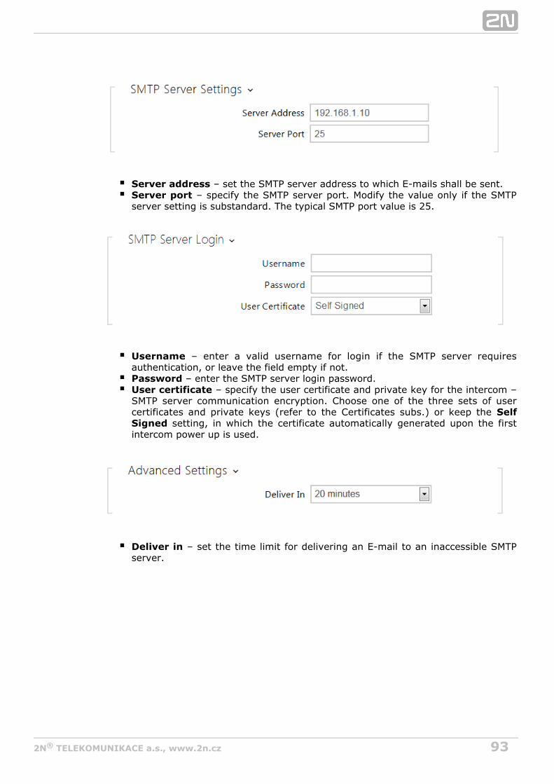
932N TELEKOMUNIKACE a.s., www.2n.cz®
Server address – set the SMTP server address to which E-mails shall be sent.Server port – specify the SMTP server port. Modify the value only if the SMTPserver setting is substandard. The typical SMTP port value is 25.
Username – enter a valid username for login if the SMTP server requiresauthentication, or leave the field empty if not.Password – enter the SMTP server login password.User certificate – specify the user certificate and private key for the intercom –SMTP server communication encryption. Choose one of the three sets of usercertificates and private keys (refer to the Certificates subs.) or keep the Self
setting, in which the certificate automatically generated upon the firstSigned intercom power up is used.
Deliver in – set the time limit for delivering an E-mail to an inaccessible SMTPserver.

942N TELEKOMUNIKACE a.s., www.2n.cz®
Click to send a testing E-mail to the defined address with the aim to testApply & Testthe functionality of the current E-mail sending setting. Enter the destination E-mailaddress into the Test E-mail address field and press the button. The current E-mailsending state is continuously displayed in the window for you to detect an E-mailsetting problem if any on the intercom or another network element.

952N TELEKOMUNIKACE a.s., www.2n.cz®
a. b. c. d.
Send E-Mail at – set E-mail sending upon outgoing phone calls. The E-Mail issent when the connection is terminated. The following options are available:
Any Outgoing call - an E-mail will be sent upon every outgoing call. Missed Outgoing call - an E-mail will be sent upon every missed outgoingcall.Via Automation - no E-mail messages will be sent upon outgoing calls. Automation have to be set up in order to send an E-mail.
Sender – enter the sender's E-mail.Default recipient – typically, the intercom sends E-mail messages to the useraddresses included in the user list. If the user's E-mail parameter is notcompleted, the messages are sent to the address included in this parameter. If arecipient is not included in the users list or this field, no E-mail is sent.Message subject – set the E-mail subject to be sent.Message body – edit the text to be sent. Use the HTML formatting marks in thetext. You can insert special symbols substituting the username, date and time,intercom identification or called number, which will be replaced with the actualvalue before sending. Refer to the table of substitute symbols below:
$User$ Called username$DateTime$ Current date and time$DialNumber$Called number$HeliosId$ Intercom identification
Note
An E-mail can always be sent via Automation.

962N TELEKOMUNIKACE a.s., www.2n.cz®
Attach snapshots – enable sending of an attachment including one or morecamera snapshots taken during ringing or calling.Number of snapshots – set the count of snapshots to be attached to the E-mailmessage.Snapshot resolution – set the snapshot resolution for the images to be sent.

972N TELEKOMUNIKACE a.s., www.2n.cz®
5.4.5 Automation
The intercom provides highly flexible setting options to satisfy variable2N Helios IP®
user needs. There are situations in which the standard configuration settings (switch orcall modes, e.g.) are insufficient and so offers 2N Helios IP® 2N Helios IP®
, a special programmable interface for applications that require complexAutomationinterconnections with third party systems.
Refer to the Configuration Manual for the 2N Helios IP Automation ® 2N Helios IP®
function and configuration details.Automation
Note
The Automation function is available with the Gold or Enhanced Integration licence only.

982N TELEKOMUNIKACE a.s., www.2n.cz®
5.4.6 HTTP API
2N Helios IP HTTP API® is an application interface designed for control of selected functions via the . It enables intercoms to be2N Helios IP® HTTP 2N Helios IP®
integrated easily with third party products, such as home automation, security andmonitoring systems, etc.
2N Helios IP HTTP API® provides the following services:
System API – provides intercom configuration changes, status info andupgrade.Switch API – provides switch status control and monitoring, e.g. door lockopening, etc.I/O API – provides intercom logic input/output control and monitoring.Camera API – provides camera image control and monitoring.Display API – provides display control and user information display.Phone/Call API – provides incoming/outgoing call control and monitoring.
Set the transport protocol ( or ) and way of authentication ( , HTTP HTTPS None Basicor ) for each function. Create up to five user accounts (with own username andDigestpassword) in the configuration for detailed access control of services andHTTP APIfunctions.
Refer to the 2N Helios IP HTTP API® Configuration Manual for the HTTP API functionand configuration details.
Note
Full HTTP API function is available with the Gold or Enhanced Integrationlicence only. Only Camera API a Switch API is available without thislicence.

992N TELEKOMUNIKACE a.s., www.2n.cz®
a. b. c. d. e. f.
5.4.7 User Sounds
The intercoms provide standard signalling of operational statuses by2N Helios IP®
tone sequences; refer to the Signalling of Operational Statuses subsection. If you findthe standard sound signalling inconvenient, modify the sounds for the followingstatuses:
Ringing before answering callCall busy toneCall hang-upInvalid inputInvalid user positionSwitch activation
You can either completely mute the above-mentioned sounds, replace them with one ofound file of your own into the intercom.the five predefined sounds, or simply record a s
The sound file must have the WAV format and use PCM encoding with 8 kHz samplingfrequency and 8/16-bit sample resolution, and the file size may not exceed 128 kB.The maximum file playing time is limited to approximately 16 seconds for 8-bit and 8seconds for 16-bit resolution.
You can also play the recorded files via Automation using the Action.PlayUserSound and, optionally, with the aid of the intercom speaker and/or directly into the phone call.

1002N TELEKOMUNIKACE a.s., www.2n.cz®
List of Parameters
Ringing before answering call – set the sound to be played before answering an incoming call (intercom ring tone).Call busy tone – set the sound to be played when the called user is busy. Call hang-up signalling – set the sound to be played upon the call end.Invalid input signalling – set the sound to be played when an invalid code in entered (switch/user/profile activation).Invalid position signalling – set the sound to be played when a quick dial button is pressed but the corresponding user position is not programmed.Switch activation signalling – set the sound to be generated when a switch is activated. Specify signalling details for each switch; refer to the Switchessubsection.
You can record up to 10 user sound files into the intercom and assign names to themfor convenience.
Press to record a sound file to the intercom. Select a file from your PC via a
dialogue window and push . Press to remove a file. Press to replay theRecord sound file (locally on your PC).


1022N TELEKOMUNIKACE a.s., www.2n.cz®
5.4.8 Audio Test
The intercoms allow you to perform periodical tests of the integrated2N Helios IP®
speaker and microphone. For the test purpose, the integrated speaker generates oneor more short beeps. The integrated microphone receives the generated tone and thetest is successful if the tone is detected correctly. The test takes approximately 4seconds. If the test fails (which may be due to an extreme surrounding noise level,e.g.), a new test is carried out in 10 minutes. The result of the last test can bedisplayed in the intercom confirmation interface or processed by the 2N Helios IP®
Automation.
List of Parameters
Audio test enabled – enable automatic execution of the audio test.
Note
The audio test is available with the Gold or Enhanced Audio licence only.

1032N TELEKOMUNIKACE a.s., www.2n.cz®
Test period – set the test period: daily or weekly.Test start time – set the test starting time in the HH:MM format. Werecommend you to set a time at which a low intercom traffic is expected.Test now – push the button to start the test immediately regardless of thecurrent settings.
Test status – this parameter displays the current test status.Last test time – this parameter displays the time of the last-performed test.Last test result – this parameter displays the result of the last-performed test.

1042N TELEKOMUNIKACE a.s., www.2n.cz®
a. b. c. d.
5.4.9 Web Server
You can configure your intercom using a standard browser which2N Helios IP®
accesses the integrated web server. Use the secured HTTPS protocol forcommunication between the browser and intercom. Having accessed the intercom,enter the login name and password. The default login name and password are aadminnd respectively. We recommend you to change the default password as soon as2n possible.
The unction is used by the following intercom functions too: Web Server f
JPEG snapshot/MJPEG video download; refer to Streaming.ONVIF protocol for video streaming, refer to Streaming.HTTP commands for switch control, refer to Switches.Event.HttpTrigger in 2N Helios IP Automation, refer to the respectivemanual.
The unsecured HTTP protocol can be used for these special communication cases.
List of Parameters
Device name – set the device name to be displayed in the right upper corner ofthe web interface, login window and other applications if available (2N Helios IP®
Manager, 2N Helios IP Network Scanner, etc).®Web interface language – set the default language for administration webserver login. Use the upper toolbar buttons to change the language temporarily.

1052N TELEKOMUNIKACE a.s., www.2n.cz®
Password – set the intercom access password. Press to change thepassword. The 8-character password must include one lower-case letter, oneupper-case letter and one digit at least.
HTTP port – set the web server port for HTTP communication. The port settingwill not be applied until the intercom gets restarted.HTTPS port – set the web server port for HTTPS communication. The portsetting will not be applied until the intercom gets restarted.HTTPS user certificate – specify the user certificate and private key for theintercom HTTP server – user web browser communication encryption. Chooseone of the three sets of user certificates and private keys (refer to theCertificates subsection) or keep the setting, in which the certificateSelfSigned automatically generated upon the first intercom power up is used.Remote access enabled – enable remote access to the intercom web serverfrom off-LAN IP addresses.
– download the original file containing all the user interfaceOriginal languagetexts in English. The file format is XML; see below.
– record, load and remove, if necessary, a user file containingUser languageyour own user interface text translations.

1062N TELEKOMUNIKACE a.s., www.2n.cz®
<?xml version="1.0" encoding="UTF-8"?><strings language="English" languageshort="EN"> <!-- Global enums--> <s id="enum/error/1">Invalid value!</s> <s id="enum/bool_yesno/0">NO</s> <s id="enum/bool_yesno/1">YES</s> <s id="enum/bool_user_state/0">ACTIVE</s> <s id="enum/bool_user_state/1">INACTIVE</s> <s id="enum/bool_profile_state/0">ACTIVE</s> <s id="enum/bool_profile_state/1">INACTIVE</s> .. .. ..</strings>
While translating, modify the value of elements only. Do not modify the values.<s> id The language name specified by the attribute of the element willlanguage <strings>be available in the selections of the Web interface language parameter. Theabbreviation of the language name specified by the attribute of the languageshort
element will be included in the language list in the right-hand upper corner<strings>of the window and will be used for a quick language switching.

1072N TELEKOMUNIKACE a.s., www.2n.cz®
5.4.10 SNMP
The intercoms integrate a remote intercom supervision functionality 2N® Helios IPvia the SNMP. The integrated SNMP agent becomes available when the Enhanced
licence key is added. The intercoms support the SNMP version 2c.Integration
List of Parameters
Community string - text string representing the access key to the MIB tableobjects.
- IP address to which the SNMP traps are to be sent.Trap IP address - download the current MIB definition from a device.Download MIB file
Contact - enter the device manager contact (name, e-mail, etc.). - enter the device name.Name
- enter the device location (1st floor, e.g.).Location

1082N TELEKOMUNIKACE a.s., www.2n.cz®
IP address - enter up to 4 valid IP addresses for SNMP agent access to blockaccess from other addresses. If the field is empty, the device may be accessedfrom any IP address.

1092N TELEKOMUNIKACE a.s., www.2n.cz®
5.5 SystemHere is what you can find in this section:
5.5.1 Network5.5.2 Date and Time5.5.3 Licence5.5.4 Certificates5.5.5 Auto Provisioning5.5.6 Syslog5.5.7 Maintenance

1102N TELEKOMUNIKACE a.s., www.2n.cz®
5.5.1 Network
As the intercom is connected to the LAN, make sure that its IP address2N Helios IP®
has been set correctly or obtained from the LAN DHCP server. Configure the IP addressand DHCP in the subsection.Network
If you use the RADIUS server and 802.1x-based verification of connected equipment,you can make the intercom use the EAP-MD5 or EAP-TLS authentication. Set thisfunction in the tab.802.1x
The tab helps you launch capture of incoming and outgoing packets on theTraceintercom network interface. The file with captured packets can be downloaded forWireshark processing, e.g. (www.wireshark.org).
List of Parameters
Network
Use DHCP server – enable automatic obtaining of the IP address from the LANDHCP server. If the DHCP server is unavailable or inaccessible in your LAN, usethe manual network settings.
Tip
To know the current IP address of your intercom, use the 2N Helios IP®
, which can be freely downloaded from , or apply theScanner www.2n.czsteps described in the Installation Manual of the respective intercom: theintercom communicates its IP address to you via a voice function.

1112N TELEKOMUNIKACE a.s., www.2n.cz®
Static IP address – static IP address of the intercom, which is used togetherwith the below mentioned parameters if the parameter isUse DHCP Serverdisabled.Network mask – network mask.Default gateway – address of the default gateway, which providescommunication with off-LAN equipment.Primary DNS – primary DNS server address for translation of domain names toIP addresses.Secondary DNS – secondary DNS server address, which is used in case theprimary DNS is inaccessible.
802.1x
Device identity – username (identity) for authentication via EAP-MD5 andEAP-TLS.
MD5 authentication enabled – enable authentication of network devices viathe 802.1x EAP-MD5 protocol. Do not enable this function if your LAN does notsupport 802.1x. If you do so, the intercom will become inaccessible.Password – enter the access password for EAP-MD5 authentication.

1122N TELEKOMUNIKACE a.s., www.2n.cz®
TLS authentication enabled – enable authentication of network devices via the802.1x EAP-TLS protocol. Do not enable this function if your LAN does notsupport 802.1x. If you do so, the intercom will become inaccessible.Trusted certificate – specify the set of trusted certificates for verification of theRADIUS server public certificate validity. Choose one of three sets of certificates;refer to the Certificates subsection. If no trusted certificate is included, theRADIUS public certificate is not verified.User certificate – specify the user certificate and private key for verification ofthe intercom authorisation to communicate via the 802.1x-secured networkelement port in the LAN. Choose one of three sets of user certificates and privatekeys; refer to the Certificates subsection.
TraceIn the tab, you can launch capturing of incoming and outgoing packets on theTraceintercom network interface. The captured packets are stored in a 4 MB buffer. Whenthe buffer fills up, the oldest packets are overwritten automatically. We recommendyou to lower the video stream transmission rate below 512 kbps while capturing. Press
to start, to stop and to download the packet capture file.
Poznámka
This function is available with the Gold or Enhanced Security licence only.

1132N TELEKOMUNIKACE a.s., www.2n.cz®
5.5.2 Date and Time
If you control validity of phone numbers, lock activation codes and similar by timeprofiles, make sure that the intercom internal date and time are set correctly.
Most models are equipped with a back-up real-time clock to withstand2N Helios IP®
up to several days' long power outages. If not equipped with this function, the intercomloses the real time data upon power outage (or restart). Therefore, if the intercom ispowered up after a rather long period of time (after new intercom installation, e.g.),time is set to the default value and has to be reset. You can synchronise the intercomtime with your PC anytime by pressing the button.Synchronise
Synchronise the intercom internal time with any available SNTP server if your intercomis not equipped with a real-time clock.
Practically, the intercom real-time circuit accuracy is approximately ±0,005 %, whichmay mean a deviation of 2 minutes per month. Therefore, we recommend you to±synchronise time with the NTP server to achieve the highest accuracy and reliability.The intercom sends a query to the NTP server periodically to update its time value.
List of Parameters
Synchronise – push the button to synchronise the intercom time value with your PC
Note
The intercom does not need the basiccurrent date and time values for its function. However, be sure to set these values when you apply timeprofiles and display time of listed events (Syslog, used cards, logsdownloaded by HTTP API, etc.).2N Helios IP®

1142N TELEKOMUNIKACE a.s., www.2n.cz®
Synchronise – push the button to synchronise the intercom time value with your PCtime value.
Time zone – set the time zone for the installation site to define time shifts andwinter/summer time transitions.Time zone rule – if the intercom is installed on a site that it not included in the
parameter, set the time zone rule manually. The rule is applied onlyTime zoneif the parameter is set to .Time zone Manual
Use NTP server – enable the NTP server use for intercom time synchronisation.NTP server address – set the IP address/domain name of the NTP server usedfor your intercom time synchronisation.

1152N TELEKOMUNIKACE a.s., www.2n.cz®
5.5.3 Licence
Some functions are available with a valid licence key only. Refer to the2N Helios IP®
subsection for the list of intercom Model Differences and Function Licensing licensing options.
List of Parameters
Licence key – enter the valid licence key.Licence key valid – check whether the used licence key is valid.
Enhanced security – check whether the functions activated by the Enhanced

1162N TELEKOMUNIKACE a.s., www.2n.cz®
Security licence are available.Enhanced audio – check whether the functions activated by the Enhanced Audiolicence are available.Enhanced video – check whether the functions activated by the EnhancedVideo licence are available.Enhanced integration – check whether the functions activated by the EnhancedIntegration licence are available.NFC support - check whether the NFC user identification support is available.
- check whether the G.729 audio codec is available.G.729 support - check whether the InformaCast support is available.InformaCast support
Trial licence state – check the trial licence state (non-activated, activated,expired).Licence expiry – check the remaining time of the trial licence validity.

1172N TELEKOMUNIKACE a.s., www.2n.cz®
a. b. c. d.
5.5.4 Certificates
Some network services use the Transaction Layer Security (TLS)2N Helios IP®
protocol for communication with other LAN devices to prevent third parties frommonitoring and/or modifying the communication contents. Unilateral or bilateralauthentication based on certificates and private keys is needed for establishingconnections via TLS.
The following intercom services use the TLS protocol:
Web server (HTTPS)E-mail (SMTP)802.1x (EAP-TLS)SIP
The intercom allows you to load up to three sets of trusted certificates,2N Helios IP®
which help authenticate LAN devices for communication with the intercom, and threesets of user certificates and private keys for communication encryption.
Each certificate-requiring service can be assigned one of the three certificate setsavailable; refer to the , and subsections. TheWeb Server E-Mail Streaming certificates can be shared by the services.
2N Helios IP® accepts the DER (ASN1) and PEM certificate formats.
Upon the first power up, the intercom automatically generates the Self Signedfor the and without forcing you tocertificate and private key Web Server E-Mail
load a certificate and private key of your own.
Refer to the tables below for the current list of trusted and user certificates:
Note
If you use the Self Signed certificate for encryption of the intercom webserver – browser communication, the communication is secure, but thebrowser will warn you that it is unable to verify the intercom certificate
validity.

1182N TELEKOMUNIKACE a.s., www.2n.cz®
Press to load a certificate saved on your PC. Select the certificate (or private key)
file in the dialogue window and push . Press to remove a certificate from theLoadintercom.

1192N TELEKOMUNIKACE a.s., www.2n.cz®
a. b.
c.
a. b. c. d. e. f.
5.5.5 Auto Provisioning
The intercoms help you update firmware and configuration manually,2N Helios IP®
or automatically from a storage on a TFTP/HTTP server selected by you according topredefined rules.
You can configure the TFTP and HTTP server address manually. The int2N Helios IP®
ercoms support automatic identification of the local DHCP server address (Option 66).
Firmware
Use the tab to set automatic firmware download from a server defined byFirmwareyou. The intercom compares the server file with its current firmware file periodicallyand, if the server file is later, automatically updates firmware and gets restarted(approx. 30 s). Hence, we recommend you to update when the intercom traffic is verylow (at night, e.g.).
expects the following files:2N Helios IP ®
hip -firmware.bin – intercom firmwareMODELhip -common.xml – common configuration for all intercoms of oneMODELmodelhip - .xml – specific configuration for one intercomMODEL MACADDR
MODEL in the filename specifies the intercom model:
v – 2N Helios IP Vario®
f – 2N Helios IP Force®
sf – 2N Helios IP Safety®
ak – 2N Helios IP Audio Kit®
vk – 2N Helios IP Video Kit®
ve – 2N Helios IP Verso®
MACADDR is the MAC address of the intercom in the 00-00-00-00-00-00 format. Findthe MAC address on the intercom production plate or in the tab viaIntercom Status the web interface.
Example:

1202N TELEKOMUNIKACE a.s., www.2n.cz®
2N Helios IP Vario® with MAC address 00-87-12-AA-00-11 downloads the followingfiles from the TFTP server:
hipv-firmware.binhipv-common.xmlhipv-00-87-12-aa-00-11.xml
Configuration
Use the tab to set automatic configuration download from the serverConfigurationdefined by you. The intercom periodically downloads a file from the server and getsreconfigured without getting restarted.
List of Parameters
Firmware update enabled – enable automatic firmware/configuration updatingfrom the TFTP/HTTP server.
Address retrieval mode – select whether the TFTP/HTTP server address shallbe entered manually or a value retrieved automatically from the DHCP serverusing Option 66 shall be used.Server address – enter the TFTP (tftp://ip_address), HTTP ( )http://ip_addressor HTTPS ( ) server address manually.https://ip_addressDHCP (Option 66/150) address – check the server address retrieved via theDHCP Option 66 or 150.File path – set the firmware/configuration filename directory or prefix on theserver. The intercom expects the XhipY_firmware.bin, XhipY-common.xml andXhipY-MACADDR.xml files, where X is the prefix specified herein and Y specifiesthe intercom model.
Note
A few seconds' interruption of the display function occurs in thedisplay-equipped models during reconfiguration.2N Helios IP Vario®
Therefore, we recommend you to update when the intercom traffic is verylow (at night, e.g.).

1212N TELEKOMUNIKACE a.s., www.2n.cz®
At boot time – enable check and, if possible, update execution upon everyintercom start.Update period – set the update period: hourly, daily, weekly and monthly.Update at – set the update time in the HH:MM format for periodical updating ata low-traffic time. The parameter is not applied if the update period is set to avalue shorter than 1 day.Next update at – set the next update time.
Last update at - last update time.Update result - last update result. The following options are available:
Result DescriptionPending... Update in progressUpdateSucceeded
The configuration/firmware update has been successful. Withfirmware update, the device will be restarted in a few seconds.
Firmware IsUp To Date
A firmware update attempt reveals that the latest firmwareversion is used.
DHCPOption 66Failed
Server address loading via DHCP Option 66 or 150 has failed.
InvalidDomainName
The server domain name is invalid due to wrong configuration orunavailability of the DNS server.
Server NotFound The requested HTTP/TFTP server fails to reply.
DownloadFailed An unspecified error occurred during file download.
File NotFound The file has not been found on the server.
File IsInvalid The file to be downloaded is corrupted or of a wrong type.

1222N TELEKOMUNIKACE a.s., www.2n.cz®
5.5.6 Syslog
The intercoms allow you to send system messages to the Syslog server2N Helios IP®
including relevant information on the device states and processes for recording,analysis and audit. It is unncecessary to configure this service for common intercomoperation.
List of Parameters
Send Syslog messages – enable sending of system messages to the Syslogserver. Make sure that the server address is set correctly.
Server address – set the IP/MAC address of the server on which the Syslogapplication is running.Severity level – set the severity level of the messages to be sent.

1232N TELEKOMUNIKACE a.s., www.2n.cz®
5.5.7 Maintenance
Use this menu to maintain your intercom configuration and firmware. You can back upand reset all parameters, update firmware and/or reset default settings here.
Back up configuration – back up the complete current configuration of yourintercom. Press the button to download the configuration file to your PC.
Reset configuration – reset configuration from the preceding backup. Press thebutton to display a dialogue window for you to select and upload theconfiguration file to the intercom. You can also choose before uploading whetherthe network parameters and SIP exchange connection settings from theconfiguration file shall be applied.Default state – reset default values for all of the intercom parameters exceptfor the network settings. Use the respective jumper or push to reset allResetthe intercom parameters; refer to the Installation Manual of your intercom.
Upgrade firmware – upgrade your intercom firmware. Press the button todisplay a dialogue window for you to select and upload the firmware file to theintercom. The intercom will automatically get restarted and new FW will then beavailable. The whole upgrading process takes less than one minute. Refer to
. for the latest FW version for your intercom. FW upgrade does notwww.2n.czaffect configuration as the intercom checks the FW file to prevent upload of awrong or corrupted file.Restart intercom – restart the intercom. The process takes about 30 s. When
Caution
Treat the file cautiously as the intercom configuration may include delicateinformation such as user phone numbers and access codes.
Caution
The default state reset deletes the licence key if any. Hence, werecommend you to copy it to another storage for later use.

1242N TELEKOMUNIKACE a.s., www.2n.cz®
the intercom has obtained the IP address upon restart, the login window will getdisplayed automatically.

1252N TELEKOMUNIKACE a.s., www.2n.cz®
6. Supplementary Information
Zde je přehled toho, co v kapitole naleznete:
6.1 Troubleshooting6.2 Directives, Laws and Regulations6.3 General Instructions and Cautions

1262N TELEKOMUNIKACE a.s., www.2n.cz®
6.1 Troubleshooting
For the most frequently asked questions refer to .faq.2n.cz

1272N TELEKOMUNIKACE a.s., www.2n.cz®
6.2 Directives, Laws and Regulations
Europe
2N Helios IP® conforms to the following directives and regulations:
Directive 1999/5/EC of the European Parliament and of the Council, of 9 March 1999 –on radio equipment and telecommunications terminal equipment and the mutualrecognition of their conformity
Directive 2006/95/EC of the European Parliament and of the Council of 12 December2006 on the harmonisation of the laws of Member States relating to electricalequipment designed for use within certain voltage limits
Directive 2004/108/EC of the Council of 15 December 2004 on the harmonisation ofthe laws of Member States relating to electromagnetic compatibility
Commission Regulation (EC) No. 1275/2008, of 17 December 2008, implementingDirective 2005/32/EC of the European Parliament and of the Council with regard toecodesign requirements for standby and off mode electric power consumption ofelectrical and electronic household and office equipment
Directive 2011/65/EU of the European Parliament and of the Council of 8 June 2011 onthe restriction of the use of certain hazardous substances in electrical and electronicequipment
Regulation (EC) No. 1907/2006 of the European Parliament and of the Council of 18December 2006 concerning the Registration, Evaluation, Authorisation and Restrictionof Chemicals (REACH), establishing a European Chemicals Agency, amending Directive1999/45/EC and repealing Council Regulation (EEC) No. 793/93 and CommissionRegulation (EC) No. 1488/94 as well as Council Directive 76/769/EEC and CommissionDirectives 91/155/EEC, 93/67/EEC, 93/105/EC and 2000/21/EC
Directive 2012/19/EC of the European Parliament and of the Council of 4 July 2012 onwaste electrical and electronic equipment.
Industry Canada
This Class B digital apparatus complies with Canadian ICES-003. / Cet appareilnumérique de la classe B est conforme a la norme NMB-003 du Canada.

1282N TELEKOMUNIKACE a.s., www.2n.cz®
FCCNOTE: This equipment has been tested and found to comply with the limits for a ClassB digital device, pursuant to part 15 of the FCC Rules. These limits are designed toprovide reasonable protection against harmful interference in a residential installation.This equipment generates, uses and can radiate radio frequency energy and, if notinstalled and used in accordance with the instructions, may cause harmful interferenceto radio communications. However, there is no guarantee that interference will notoccur in a particular installation. If this equipment does cause harmful interference toradio or television reception, which can be determined by turning the equipment offand on, the user is encouraged to try to correct the interference by one or more of thefollowing measures:
Reorient or relocate the receiving antennaIncrease the separation between the equipment and receiverConnect the equipment into an outlet on a circuit different from that to which thereceiver is connectedConsult the dealer or an experienced radio/TV technician for help.
Changes or modifications to this unit not expressly approved by the party responsiblefor compliance could void the user's authority to operate this equipment.

1292N TELEKOMUNIKACE a.s., www.2n.cz®
6.3 General Instructions and Cautions
Please read this User Manual carefully before using the product. Follow all instructionsand recommendations included herein.
Any use of the product that is in contradiction with the instructions provided hereinmay result in malfunction, damage or destruction of the product.
The manufacturer shall not be liable and responsible for any damage incurred as aresult of a use of the product other than that included herein, namely undue applicationand disobedience of the recommendations and warnings in contradiction herewith.
Any use or connection of the product other than those included herein shall beconsidered undue and the manufacturer shall not be liable for any consequences arisenas a result of such misconduct.
Moreover, the manufacturer shall not be liable for any damage or destruction of theproduct incurred as a result of misplacement, incompetent installation and/or undueoperation and use of the product in contradiction herewith.
The manufacturer assumes no responsibility for any malfunction, damage ordestruction of the product caused by incompetent replacement of parts or due to theuse of reproduction parts or components.
The manufacturer shall not be liable and responsible for any loss or damage incurred asa result of a natural disaster or any other unfavourable natural condition.
The manufacturer shall not be held liable for any damage of the product arising duringthe shipping thereof.
The manufacturer shall not make any warrant with regard to data loss or damage.
The manufacturer shall not be liable and responsible for any direct or indirect damageincurred as a result of a use of the product in contradiction herewith or a failure of theproduct due to a use in contradiction herewith.
All applicable legal regulations concerning the product installation and use as well asprovisions of technical standards on electric installations have to be obeyed. Themanufacturer shall not be liable and responsible for damage or destruction of theproduct or damage incurred by the consumer in case the product is used and handledcontrary to the said regulations and provisions.
The consumer shall, at its own expense, obtain software protection of the product. Themanufacturer shall not be held liable and responsible for any damage incurred as aresult of the use of deficient or substandard security software.
The consumer shall, without delay, change the access password for the product afterinstallation. The manufacturer shall not be held liable or responsible for any damageincurred by the consumer in connection with the use of the original password.
The manufacturer also assumes no responsibility for additional costs incurred by theconsumer as a result of making calls using a line with an increased tariff.

1302N TELEKOMUNIKACE a.s., www.2n.cz®
Electric Waste and Used Battery Pack Handling
Do not place used electric devices and battery packs into municipal waste containers.An undue disposal thereof might impair the environment!
Deliver your expired electric appliances and battery packs removed from them todedicated dumpsites or containers or give them back to the dealer or manufacturer forenvironmental-friendly disposal. The dealer or manufacturer shall take the productback free of charge and without requiring another purchase. Make sure that the devicesto be disposed of are complete.
Do not throw battery packs into fire. Battery packs may not be taken into parts orshort-circuited either.

1312N TELEKOMUNIKACE a.s., www.2n.cz®
2N TELEKOMUNIKACE a.s.
Modřanská 621, 143 01 Prague 4, Czech Republic
Phone: +420 261 301 500, Fax: +420 261 301 599
E-mail: [email protected]
Web: www.2n.cz
1759v2