26 lecture lam - university of hawaiiplam/ph272_summer/l6/26_lecture_lam.pdf · introduction • in...
TRANSCRIPT

Copyright © 2008 Pearson Education Inc., publishing as Pearson Addison-Wesley
PowerPoint® Lectures for
University Physics, Twelfth Edition
– Hugh D. Young and Roger A. Freedman
Lectures by James Pazun
Chapter 26
Direct-Current Circuits
Modified by P. Lam 7_23_2008

Copyright © 2008 Pearson Education Inc., publishing as Pearson Addison-Wesley
Topics for Chapter 26
• Resistors in series and parallel circuit.
• Kirchoff’s Rules.
Intermission
• R-C circuits

Copyright © 2008 Pearson Education Inc., publishing as Pearson Addison-Wesley
Introduction
• In the last chapter, we gainedinsight about how current flowsthrough a resistor in simpleexamples like a light bulbattached to a battery.
• Now, imagine many thousandsof circuits wired onto flatwafers with structure so tinythat microscopy would benecessary to view their patterns.Understanding the next step andmastering more complex circuitpatterns is the goal forChapter 26.

Copyright © 2008 Pearson Education Inc., publishing as Pearson Addison-Wesley
Resistors in series and parallel I
• If we took three resistors
and considered the
different ways they
could be connected, we
arrive at the four
possibilities illustrated
in Figure 26.1.

Copyright © 2008 Pearson Education Inc., publishing as Pearson Addison-Wesley
Equivalent resistance for series and parallel circuits
Series resistors :
(1) Same current through all resistors = I
(2) Total voltage V = V1 +V2 +V2
V = IR1 + IR2 + IR3 = IReq
Req = R1 + R2 + R3
Parallel resistors :
(1) Same voltage across all resistors = V
(2) Total current I = I1 + I2 + I2
I =V
R1
+V
R2
+V
R3
=V
Req
1
Req
=1
R1
+1
R2
+1
R3
Note : Formula for combining resistance
are "opposite" to those for combining capacitance.
Reason : V = IR but V = Q1C

Copyright © 2008 Pearson Education Inc., publishing as Pearson Addison-Wesley
Examples of Resistors in series and parallel
• If you have ever wired a Christmas tree with a series of lights
(resistors) in series, you know what happens if just one burns out.
The lights have become an open circuit and will not function.
• Car headlights are a good example of resistors wired in parallel. If
one light burns out, the circuit changes but still functions to allow
the driver a safe trip to repair. See Figure 26.2 below.

Copyright © 2008 Pearson Education Inc., publishing as Pearson Addison-Wesley
Example of Resistors in series and parallel—combinations
Follow Example 26.1, find I through each resistor.

Copyright © 2008 Pearson Education Inc., publishing as Pearson Addison-Wesley
Equivalent resistance method is not always useful
• The two circuits below CANNOT be reduced to simple series-parallel combination of resistors.
(a) When there are more than
one battery
(b) The arrangement of resistors
is simply neither series nor
parallel (the spoiler is middle
resistor).

Copyright © 2008 Pearson Education Inc., publishing as Pearson Addison-Wesley
Kirchoff’s Rules I—junctions
• Kirchoff’s Rules: (1) Junction rule and (2) Loop rule can be usedto find current and voltages for any circuit.
Note:(1) Junction rule = conservation of charge
(2) You may ASSUME the direction of the current; if your final anwer is then the
actual current flows in the opposite direction.

Copyright © 2008 Pearson Education Inc., publishing as Pearson Addison-Wesley
Kirchoff’s Rules II—loops
• The algebraic sum of thepotential differences inany loop must equal zero.
• Example:
I1 I2I3
Loop 1 in fig. a (take c as the starting point)
+ 1 I1r1 + I2R = 0
Loop 2 : (take c as the starting point)
+ 1 I1r1 I3r2 2 = 0
Loop 3 : (take b as the starting point)
You try it!
Suppose all the emf and resistance are given.
The three unknowns are I1,I2,and I3.
We have 3 loop equations plus 1 junction equation
I1 + I2 = I3
Do we have too many equations?

Copyright © 2008 Pearson Education Inc., publishing as Pearson Addison-Wesley
Kirchoff’s Rules - convention for potentials in loop equation.
Think of direction of current as
direction of water flow in a
water fall, which flows from
high gravitational potential to
low gravitational potential

Copyright © 2008 Pearson Education Inc., publishing as Pearson Addison-Wesley
Kirchoff’s Rules—examples
Find the unknowns: , I, and r

Copyright © 2008 Pearson Education Inc., publishing as Pearson Addison-Wesley
Kirchoff’s Rules—examples
Find I1, I2, and I3

Copyright © 2008 Pearson Education Inc., publishing as Pearson Addison-Wesley
Power distribution systems—a home
• Potential, resistors, outlets, input from the power company … no
wonder electricians are integral contractors in home construction!

Copyright © 2008 Pearson Education Inc., publishing as Pearson Addison-Wesley
Intermission

Copyright © 2008 Pearson Education Inc., publishing as Pearson Addison-Wesley
R-C circuits -charging (qualitative)
Sketch the qualitative behavior of Vc(t), VR(t), I(t).
(Let the switch be closed at t-0)
Label your graphs with numerical values;
given: =10V,R=5 ,C=4F, initial charge on capacitor=0.

Copyright © 2008 Pearson Education Inc., publishing as Pearson Addison-Wesley
RC-circuit - discharging (qualitative)
Follow Examples 26.12 and 26.13.
Express Io in terms of Qo, R and C

Copyright © 2008 Pearson Education Inc., publishing as Pearson Addison-Wesley
RC-circuit - discharging (quantitative)
• Follow Examples 26.12 and 26.13.
Kirchoff’s loop rule: a ->b->c->a
IRQ
C= 0 Note : I =
dQ
dt
(Based on the direction of the current, I = positive
but dQ/dt is negative)
RdQ
dt+Q
C= 0
dQ
dt+Q
RC= 0
dQ
dt=
Q
RC
This is called "first - order, linear, homegeneous differentia equation" (D.E.).
Think of a function whose derivative is
a constant times the function?
Q(t) = AeBt
Substitute into the D.E. B = -1
RCA is set by the initial condition, A = Q(t = 0) = Qo
Q(t) = Qoet /RC ; RC = time constant
I(t) =dQ
dt=
Qo
RCe t/RC
(Compare Q(t) and I(t) with the graphs on the previous slide)
Vc (t) =Q(t)C
=Qo
Ce t /RC and VR = IR =
Qo
Ce t /RC

Copyright © 2008 Pearson Education Inc., publishing as Pearson Addison-Wesley
RC-circuit - charging (quantitative)
Kirchoff’s loop rule: a ->b->c->aIR
Q
C+ = 0 IR +
Q
C=
Note :Now I = +dQ
dt (I is positive and
dQ
dt is positive)
RdQ
dt+Q
C=
This is called "first - order, linear, inhomegeneous differentia equation" (D.E.).
The solution to this D.E. has two parts :
inhomogeneous solution (or called steady state solution) +
homogenous solution (or called transient solution)
Steady state solution : (i.e. dQ/dt = 0) Qsteady = C
Homogeneous solution : Q(t)homogeneous = Ae t /RC
Complete solution : Q(t) =C + Ae t /RC
Again, A is set by the initial condition.
Q(t = 0) = Qo = C + A A =Qo C
For the case where Qo = 0, then A = -C
Q(t) =C [1 e t /RC ]
I(t) =dQdt
=CRC
e t/RC =R
e t/RC
(Compare Q(t) and I(t) with the graphs on the earlier slide)
Vc (t) =Q(t)
C and VR = I(t)R
Copyright © 2008 Pearson Education Inc., publishing as Pearson Addison-Wesley
Complicated RC-circuit
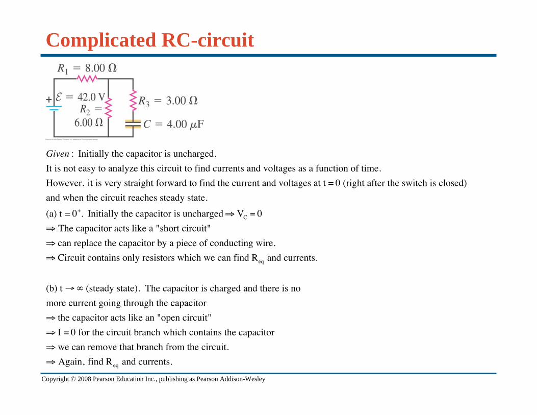
Given : Initially the capacitor is uncharged.
It is not easy to analyze this circuit to find currents and voltages as a function of time.
However, it is very straight forward to find the current and voltages at t = 0 (right after the switch is closed)
and when the circuit reaches steady state.
(a) t = 0+. Initially the capacitor is uncharged VC = 0
The capacitor acts like a "short circuit"
can replace the capacitor by a piece of conducting wire.
Circuit contains only resistors which we can find Req and currents.
(b) t (steady state). The capacitor is charged and there is no
more current going through the capacitor
the capacitor acts like an "open circuit"
I = 0 for the circuit branch which contains the capacitor
we can remove that branch from the circuit.
Again, find Req and currents.