258486-001 a datastick suspended solids.pdf · thermo scientific aquasensors™ datastick™...
TRANSCRIPT
Thermo Scientific AquaSensors™ DataStick™ Suspended Solids Measurement System User Guide

ROSS and the COIL trade dress are trademarks of Thermo Fisher Scientific Inc. U.S. patent 6,793,787.
AQUAfast, Cahn, ionplus, KNIpHE, No Cal, ORION, perpHect, PerpHecT, PerpHecTion, pHISA, pHuture, Pure Water, Sage, Sensing the Future, SensorLink, ROSS, ROSS Ultra, Sure-Flow, Titrator PLUS and TURBO2 are registered trademarks of Thermo Fisher.
1-888-pHAX-ION, A+, All in One, Aplus, AQUAsnap, AssuredAccuracy, AUTO-BAR, AUTO-CAL, AUTO DISPENSER, Auto-ID, AUTO-LOG, AUTO-READ, AUTO-STIR, Auto-Test, BOD AutoEZ, Cable-Free, CERTI-CAL, CISA, DataCOLLECT, DataPLUS, digital LogR, DirectCal, DuraProbe, Environmental Product Authority, Extra Easy/Extra Value, FAST QC, GAP, GLPcal, GLPcheck, GLPdoc, ISEasy, KAP, LabConnect, LogR, Low Maintenance Triode, Minimum Stir Requirement, MSR, NISS, One-Touch, One-Touch Calibration, One-Touch Measurement, Optimum Results, Orion Star, Pentrode, pHuture MMS, pHuture Pentrode, pHuture Quatrode, pHuture Triode, Quatrode, QuiKcheK, rf link, ROSS Resolution, SAOB, SMART AVERAGING, Smart CheK, SMART STABILITY, Stacked, Star Navigator 21, Stat Face, The Enhanced Lab, ThermaSense, Triode, TRIUMpH, Unbreakable pH, Universal Access are trademarks of Thermo Fisher.
© 2009 Thermo Fisher Scientific Inc. All rights reserved. All trademarks are the property of Thermo Fisher Scientific Inc. and its subsidiaries.
The specifications, descriptions, drawings, ordering information and part numbers within this document are subject to change without notice.
This publication supersedes all previous publications on this subject.

Thermo Scientific AquaSensors™
DataStick™
Suspended Solids Measurement System User Guide 1
Preface
This instruction manual serves to explain the use of the Thermo Scientific AquaSensors Suspended Solids System and is written to cover as many applications as possible. Please do not hesitate to contact Thermo Fisher Scientific or an authorized representative with questions or concerns.
The information presented in this instruction manual is subject to change without notice as improvements are made, and does not represent any commitment whatsoever on the part of Thermo Fisher Scientific.
Thermo Fisher Scientific cannot accept any responsibility for damage or malfunction of the sensor due to improper use.
Contact Information
To contact Thermo Scientific AquaSensors Technical Support:
Within the United States call 1.800.225.1480 or fax 978-232-6015.
Outside the United States call 978.232.6000 or fax 978.232.6031.
In Europe, the Middle East and Africa, contact your local authorized dealer.
Visit us on the web at www.thermo.com/processwater

Thermo Scientific AquaSensors™
DataStick™
Suspended Solids Measurement System User Guide 2
Safety Information
The Suspended Solids System shall be installed and operated only in the manner specified. Only a skilled, trained or authorized person should carry out installation, setup and operation of the sensor system.
Before using the system, make sure that is connected as specified. Failure to do so may result in permanent damage to the system of its components.
Protection against electric shock will be achieved only by observance of the corresponding installation rules.

Thermo Scientific AquaSensors™
DataStick™
Suspended Solids Measurement System User Guide 3
TABLE OF CONTENTS
1. INTRODUCTION.......................................................................................................................... 4
1.1. GENERAL INFORMATION................................................................................................................ 4
1.2. INTENDED USE............................................................................................................................... 5
2. PRODUCT DESCRIPTION.......................................................................................................... 6
3. MOUNTING HARDWARE .......................................................................................................... 9
3.1. UNION TEE.................................................................................................................................. 10
3.2. IMMERSION HARDWARE .............................................................................................................. 11
3.3. BALL VALVE............................................................................................................................... 12
3.4. WASH HEAD ............................................................................................................................... 12
4. WIRING ....................................................................................................................................... 13
5. AV38 LOCAL DISPLAY INTERFACE ..................................................................................... 15
5.1. MEASURE SCREEN OVERVIEW ..................................................................................................... 15
5.2. MENU STRUCTURE ...................................................................................................................... 17
5.3. 1-POINT (SPAN) CALIBRATION .................................................................................................... 20
5.4. ZERO CALIBRATION .................................................................................................................... 23
5.5. TEMPERATURE CALIBRATION ...................................................................................................... 25
5.6. CONFIGURATION ......................................................................................................................... 27
5.7. ANALOG OUTPUT OVERVIEW ...................................................................................................... 29
5.8. RELAY FUNCTION OVERVIEW ...................................................................................................... 30
6. AQUACOMM™ INTERFACE................................................................................................... 31
7. DIRECT PLC CONNECTIONS ................................................................................................. 31
8. SPECIFICATION ........................................................................................................................ 32
9. SUSPENDED SOLIDS ORDER MATRIX AND ACCESSORIES ........................................... 33
10. LIMITED WARRANTY ............................................................................................................. 34
11. TERMS AND CONDITIONS...................................................................................................... 35

Thermo Scientific AquaSensors™
DataStick™
Suspended Solids Measurement System User Guide 4
1. INTRODUCTION
1.1. General Information
The product is designed for continuous use in industrial process applications and complies with safety regulations currently in force. Improper use could lead to hazards for the user or a third-party, and/or adverse effects to the plant or other equipment.
Thermo Fisher Scientific does not accept any liability for damage that may arise if information in this manual is not followed. Therefore, the operating instructions and specifications must be read and understood by all persons involved in installation and operation of this equipment.
This manual identifies safety instructions and additional information by means of the following symbols:
This symbol draws attention to safety instructions and warnings of potential danger, which if neglected, could result in injury to persons and/or damage to property.
This symbol identifies additional information and instructions, which if neglected, could lead to inefficient operation and possible loss of production.
It is recommended that this manual be made accessible to everyone who may need it as a reference.
Please contact Thermo Fisher Scientific or an authorized representative with any questions.

Thermo Scientific AquaSensors™
DataStick™
Suspended Solids Measurement System User Guide 5
1.2. Intended use
The Suspended Solids System is used for continuous monitoring of suspended solids where the range of measurement is between 0 mg/l to 20,000 mg/l. The system also measures water temperature.
Any other use not mentioned here that is incompatible with the technical specifications is deemed inappropriate. The operator is solely responsible for any damage arising from such use.
Other prerequisites for appropriate use include:
• Observing the instructions, notes and requirements set out in this instruction manual.
• Observing all local safety regulations.
• Observing all warnings and cautions in the documentation regarding all products used in this measurement system, including the sensor, mounting hardware, AV38 electronics and cabling.
• Observing the prescribed environmental and operational conditions.
• Observing chemical compatibility with all wetted materials.
1.3. Safety Instructions
The Suspended Solids System should be installed and operated only by personnel familiar with the sensor and qualified for such work.
A defective Suspended Solids System should be returned to Thermo Fisher Scientific for repair or replacement. Contact Thermo Fisher Scientific to obtain a Return Material Authorization (RMA) number.
No modifications to the Suspended Solids System are allowed. The manufacturer/supplier accepts no responsibility for damage caused by unauthorized modifications. The risk is borne entirely by the user.
1.4. Removal from Service / Correct Disposal of the Suspended Solids System
Removal from Service
• Disconnect the cable wiring from the controller terminal block. • Remove the Suspended Solids System from the mounting hardware.
Correct Disposal of Unit
• When the Suspended Solids System is taken out of service, observe the local environmental regulations for correct disposal.
Thermo Scientific AquaSensors™
DataStick™
Suspended Solids Measurement System User Guide 6
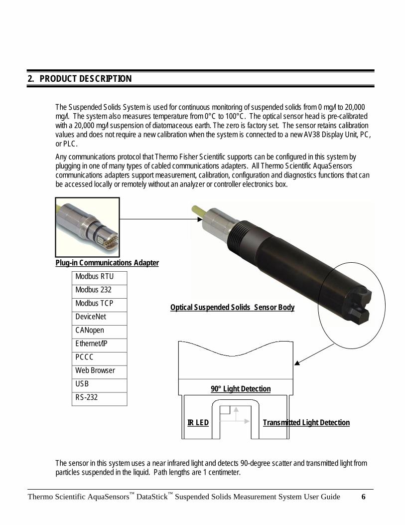
Optical Suspended Solids Sensor Body
Transmitted Light Detection IR LED
90° Light Detection
2. PRODUCT DESCRIPTION
The Suspended Solids System is used for continuous monitoring of suspended solids from 0 mg/l to 20,000 mg/l. The system also measures temperature from 0°C to 100°C. The optical sensor head is pre-calibrated with a 20,000 mg/l suspension of diatomaceous earth. The zero is factory set. The sensor retains calibration values and does not require a new calibration when the system is connected to a new AV38 Display Unit, PC, or PLC.
Any communications protocol that Thermo Fisher Scientific supports can be configured in this system by plugging in one of many types of cabled communications adapters. All Thermo Scientific AquaSensors communications adapters support measurement, calibration, configuration and diagnostics functions that can be accessed locally or remotely without an analyzer or controller electronics box.
Plug-in Communications Adapter
The sensor in this system uses a near infrared light and detects 90-degree scatter and transmitted light from particles suspended in the liquid. Path lengths are 1 centimeter.
Modbus RTU
Modbus 232
Modbus TCP
DeviceNet
CANopen
Ethernet/IP
PCCC
Web Browser
USB
RS-232
Thermo Scientific AquaSensors™
DataStick™
Suspended Solids Measurement System User Guide 7
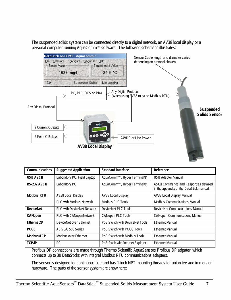
The suspended solids system can be connected directly to a digital network, an AV38 local display or a personal computer running AquaComm™ software. The following schematic illustrates:
Communications Suggested Application Standard Interface Reference
USB ASCII Laboratory PC, Field Laptop AquaComm™, Hyper Terminal® USB Adapter Manual
RS-232 ASCII Laboratory PC AquaComm™, Hyper Terminal® ASCII Commands and Responses detailed in the appendix of the DataStick manual.
Modbus RTU AV38 Local Display
PLC with Modbus Network
AV38 Local Display
Modbus PLC Tools
AV38 Local Display Manual
Modbus Communications Manual
DeviceNet PLC with DeviceNet Network DeviceNet PLC Tools DeviceNet Communications Manual
CANopen PLC with CANopenNetwork CANopen PLC Tools CANopen Communications Manual
Ethernet/IP DeviceNet over Ethernet PoE Switch with DeviceNet Tools Ethernet Manual
PCCC AB SL/C 500 Series PoE Switch with PCCC Tools Ethernet Manual
Modbus/TCP Modbus over Ethernet PoE Switch with Modbus Tools Ethernet Manual
TCP/IP PC PoE Swith with Internet Explorer Ethernet Manual
Profibus DP connections are made through Thermo Scientific AquaSensors Profibus DP adpater, which connects up to 30 DataSticks with integral Modbus RTU communications adapters.
The sensor is designed for continuous use and has 1-inch NPT mounting threads for union tee and immersion hardware. The parts of the sensor system are show here:
PC, PLC, DCS or PDA
24VDC or Line Power
2 Current Outputs
2 Form C Relays
Suspended Solids Sensor
AV38 Local Display
Any Digital Protocol
Any Digital Protocol (When using AV38 must be Modbus RTU)
Sensor Cable length and diameter varies depending on protocol chosen

Thermo Scientific AquaSensors™
DataStick™
Suspended Solids Measurement System User Guide 8
Product Highlights:
0 to 20,000 mg/l Measurement Range Calibration stored in Sensor (Does not require recalibration after connection to Analyzer/Controller) Insertion and Immersion Mounting Options 1 mg/l Resolution Fast Response Provides measurement, calibration, configuration and diagnostic functions without Analyzer/Controller Works with AV38 for local display, current output data reporting, and relay control with sensor wash. Temperature measurement included Can be connected to Modbus, DeviceNet, Ethernet, USB, RS-232 and CANopen networks.
Communications cable type and length varies depending on protocol chosen
Communications Adapter (Various Types) plug into sensor body and is tightened down with a retaining nut.
1-inch NPT threads for Union Tee and Immersion mount Hardware
Sensor Body stores calibration points and calculates suspended solids
Optical Measurement Head measures transmitted and reflected IR light.

Thermo Scientific AquaSensors™
DataStick™
Suspended Solids Measurement System User Guide 9
3. Mounting Hardware
The Suspended Solids System is mounted using the 1-inch NPT threads on the back of the sensor body. When configured with a plug-in communications adapter the sensor is 8.52 inches long from sensor tip to the end of the communications adapter body. The largest diameter of the body is 1.45 inches.
To mount this sensor into a pipe, Thermo Scientific AquaSensors 2-inch union tee is used. For immersion mounting Thermo Scientific AquaSensors immersion mount hardware with handrail mounting and ball float is available.

Thermo Scientific AquaSensors™
DataStick™
Suspended Solids Measurement System User Guide 10
3.1. Union Tee
The Suspended Solids System is threaded into the Union Tee adapter. The adapter is then set into the tee and the retaining ring is tightened down. Be sure to line up the sensor head so that the fingers of the sensor minimize blockage in the pipe.
Thread solids sensor into Union Adapter
Route sensor cable
Retaining ring: Tighten to install.
When inserting the sensor into the pipe, orient the fingers of the sensor to minimize flow restriction as shown.
Tee Extension must be set to the correct height so the sensor will be positioned properly in the process
Process Pipe.
Mounting Threads for suspended solids sensor with Communications Adapter
Thermo Scientific AquaSensors™
DataStick™
Suspended Solids Measurement System User Guide 11
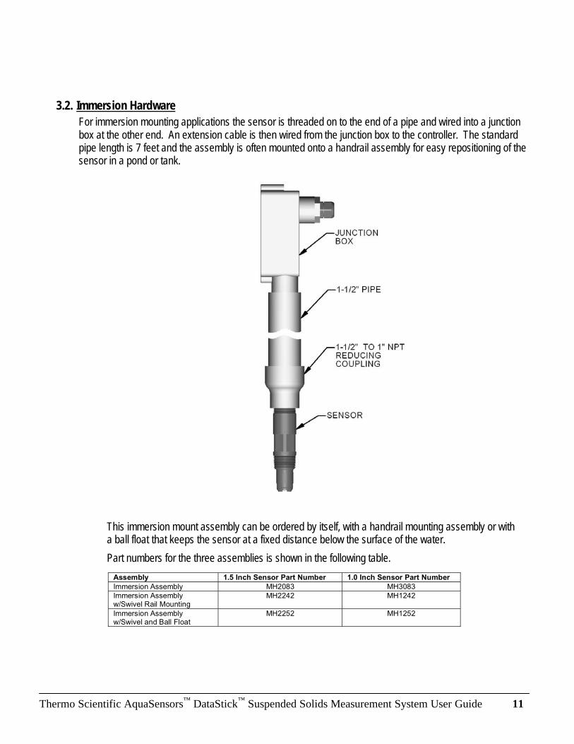
3.2. Immersion Hardware
For immersion mounting applications the sensor is threaded on to the end of a pipe and wired into a junction box at the other end. An extension cable is then wired from the junction box to the controller. The standard pipe length is 7 feet and the assembly is often mounted onto a handrail assembly for easy repositioning of the sensor in a pond or tank.
This immersion mount assembly can be ordered by itself, with a handrail mounting assembly or with a ball float that keeps the sensor at a fixed distance below the surface of the water.
Part numbers for the three assemblies is shown in the following table.
Assembly 1.5 Inch Sensor Part Number 1.0 Inch Sensor Part Number
Immersion Assembly MH2083 MH3083
Immersion Assembly w/Swivel Rail Mounting
MH2242 MH1242
Immersion Assembly w/Swivel and Ball Float
MH2252 MH1252

Thermo Scientific AquaSensors™
DataStick™
Suspended Solids Measurement System User Guide 12
3.3. Ball Valve
1.0 Inch NPT threads can be installed in 1.5-inch and 2-inch ball valve assemblies. The threads on the back of the sensor mate with threads on the end of an o-ring sealed pipe inside the ball valve assembly.
3.4. Wash Head
In applications where the sensor head is quickly fouled with sediment, a wash head assembly can be attached. The head slips on the body of the sensor and the wash nozzle is aligned with the sensor fingers. A single screw is tightened to secure the wash head to the sensor. A hose is connected from the wash head to an air compressor or water source. Actuation is controlled by an AV38 wash relay that is programmed with a wash interval and duration.
.
4.0 Max
Sensor Depth
Sensor
Wash Head
Hose Inlet
Wash Nozzle Lock Screw

Thermo Scientific AquaSensors™
DataStick™
Suspended Solids Measurement System User Guide 13
4. Wiring
Each communications adapter has a label printed at the end of the cable that indicates the supported protocol and the corresponding wiring chart. The standard cable length is 10 feet with the idea that the cable will terminate in a junction box. It is however possible to order the communications adapter with any length of cable up to the maximum allowed by the particular protocol being used. In practice all adapters have four wires and a shield. Any Class 2 DC power supply that provides 24VDC can be used.
For DeviceNet, Modbus and RS-232 cables, the RED and BLACK wires are for power, the BLUE and WHITE wires are for communications, and a bare shield wire is connected to EARTH GROUND for safety and electromagnetic immunity and emissions.
All Ethernet Adapters (Ethernet/IP, Modbus TCP, PCCC and TCP/IP) are terminated with an RJ45 connector that plugs in to any PoE switch or power injector.
All USB Adapters are terminated with a USB connector that plugs into most PC’s. The host computer supplies power.
When an AV38 local display is used, the sensor must be configured with a Modbus RTU communications adapter.
Color DeviceNet Modbus RTU RS-232
RED 24 VDC 12 to 30 VDC 12 to 30 VDC
BLACK Signal Ground
Signal Ground Signal Ground
BLUE CAN_L Comms (-) Rx
WHITE CAN_H Comms (+) Tx
SHIELD Earth Earth Earth

Thermo Scientific AquaSensors™
DataStick™
Suspended Solids Measurement System User Guide 14
Potted Serial number and Part number.
The communications adapters are keyed and plug into the end of the solids sensor. Insert the communications adapter until it bottoms out. Rotate the adapter until it engages with the connector. Push in gently and then tighten the retaining ring with a 15/16-inch wrench.
Retaining Ring: Insert the Adapter into the DataStick™ and rotated until it engages. Tighten the retaining ring to lock down the adapter. Use a 15/16 inch (24mm) wrench. Rotate clockwise to tighten.
O-Ring seal should be free of dirt when inserted in the solids sensor body.
Thermo Scientific AquaSensors™
DataStick™
Suspended Solids Measurement System User Guide 15
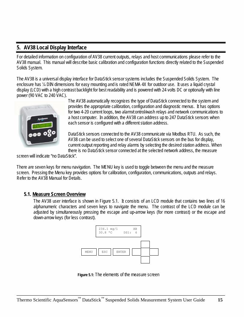
5. AV38 Local Display Interface
For detailed information on configuration of AV38 current outputs, relays and host communications please refer to the AV38 manual. This manual will describe basic calibration and configuration functions directly related to the Suspended Solids System. The AV38 is a universal display interface for DataStick sensor systems includes the Suspended Solids System. The enclosure has DIN dimensions for easy mounting and is rated NEMA 4X for outdoor use. It uses a liquid crystal display (LCD) with a high contrast backlight for best readability and is powered with 24 volts DC or optionally with line power (90 VAC to 240 VAC).
The AV38 automatically recognizes the type of DataStick connected to the system and provides the appropriate calibration, configuration and diagnostic menus. It has options for two 4-20 current loops, two alarm/control/wash relays and network communications to a host computer. In addition, the AV38 can address up to 247 DataStick sensors when each sensor is configured with a different station address. DataStick sensors connected to the AV38 communicate via Modbus RTU. As such, the AV38 can be used to select one of several DataStick sensors on the bus for display, current output reporting and relay alarms by selecting the desired station address. When there is no DataStick sensor connected at the selected network address, the measure
screen will indicate “no DataStick”. There are seven keys for menu navigation. The MENU key is used to toggle between the menu and the measure screen. Pressing the Menu key provides options for calibration, configuration, communications, outputs and relays. Refer to the AV38 Manual for Details.
5.1. Measure Screen Overview
The AV38 user interface is shown in Figure 5.1. It consists of an LCD module that contains two lines of 16 alphanumeric characters and seven keys to navigate the menu. The contrast of the LCD module can be adjusted by simultaneously pressing the escape and up-arrow keys (for more contrast) or the escape and down-arrow keys (for less contrast).
234.1 mg/l AB
30.8 °C DS1: 6
MENU ESC ENTER � �
�
�
Figure 5.1: The elements of the measure screen
Thermo Scientific AquaSensors™
DataStick™
Suspended Solids Measurement System User Guide 16
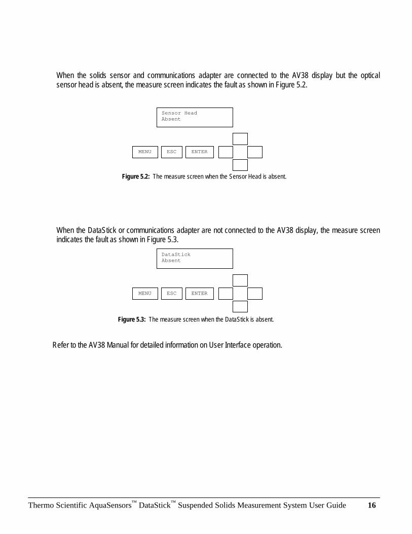
Figure 5.2: The measure screen when the Sensor Head is absent.
Figure 5.3: The measure screen when the DataStick is absent.
When the solids sensor and communications adapter are connected to the AV38 display but the optical sensor head is absent, the measure screen indicates the fault as shown in Figure 5.2.
When the DataStick or communications adapter are not connected to the AV38 display, the measure screen indicates the fault as shown in Figure 5.3.
Refer to the AV38 Manual for detailed information on User Interface operation.
Sensor Head Absent
MENU ESC ENTER � �
�
�
DataStick Absent
MENU ESC ENTER � �
�
�

Thermo Scientific AquaSensors™
DataStick™
Suspended Solids Measurement System User Guide 17
Table 5.1: AV38 Main Menu Functions
5.2. Menu Structure
Pressing the menu key while a measure screen is displayed accesses the main menu. The items in the main menu are the same regardless of the type of sensor head that is installed in the DataStick. Table 5.1 shows all accessible functions including optional features.
Main Menu Option Function
Calibrate
(Station Number)
Sensor calibration choices are automatically available for installed sensor head.
Enter the MENU from the measure display of interest – station in lower right.
Configure
(Station Number)
Configuration choices are automatically available for the installed sensor head.
Enter the MENU from the measure display of interest – station in lower right.
DataStick Comms Set the station address, baud rate and parity for the Modbus DataStick of
interest.
Hold Outputs Holds the 4-20 mA and Relay outputs
Analog Output 1 Set 4 mA and 20 mA values. Calibrate and test the current output with a meter.
Analog Output 2 (option) Set 4 mA and 20 mA values. Calibrate and test the current output with a meter.
Relay A (option) Set timer, alarm, or control functions. (Optional)
Relay B (option) Set timer, alarm, or control functions. (Optional)
Help Indicates AV38 software version
Reset AV38 Resets AV38 configuration to default current output, relay and PID settings.
Exit Returns to the measure screen
The main menu is navigated using the up/down arrows to display a desired function. The (�) symbol is used to indicate main menu choices.
To select a menu choice, press the ENTER key when the desired choice is displayed.
To return to the measure screen, press the ESC key.
When ever there is a value to be entered or a choice to be made, the second line of the display will be surrounded by parentheses (( )). The name of the value being entered or choice being made will appear on the upper line of the screen and be appended with a question mark (?) to indicate that the user is to provide input. Figure 5.4 shows the list of standard menu choices and optional menu choices in the context of the AV38 display presentation.
Thermo Scientific AquaSensors™
DataStick™
Suspended Solids Measurement System User Guide 18
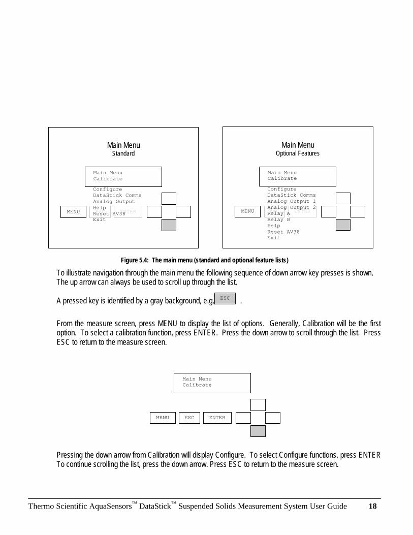
Figure 5.4: The main menu (standard and optional feature lists)
To illustrate navigation through the main menu the following sequence of down arrow key presses is shown. The up arrow can always be used to scroll up through the list. A pressed key is identified by a gray background, e.g., .
From the measure screen, press MENU to display the list of options. Generally, Calibration will be the first option. To select a calibration function, press ENTER. Press the down arrow to scroll through the list. Press ESC to return to the measure screen.
Pressing the down arrow from Calibration will display Configure. To select Configure functions, press ENTER To continue scrolling the list, press the down arrow. Press ESC to return to the measure screen.
�Main Menu �Calibrate
MENU ESC ENTER � �
�
�
�Main Menu �Calibrate
MENU ESC ENTER � �
�
�
�Configure �DataStick Comms
�Analog Output
�Help
�Reset AV38 �Exit
Main Menu Standard
ESC
�Main Menu �Calibrate
MENU ESC ENTER � �
�
�
�Configure
�DataStick Comms
�Analog Output 1
�Analog Output 2 �Relay A
�Relay B
�Help
�Reset AV38 �Exit
Main Menu Optional Features

Thermo Scientific AquaSensors™
DataStick™
Suspended Solids Measurement System User Guide 19
Pressing the down arrow from Configure will display DataStick Comms. To select DataStick Comms functions, press ENTER. To continue scrolling the list, press the down arrow. Press ESC to return to the measure screen.
Pressing the down arrow from DataStick Comms will display Analog Output. To select analog output functions, press ENTER To continue scrolling the list, press the down arrow. Press ESC to return to the measure screen.
Pressing the down arrow from Analog Output will display Help. To select Help functions, press ENTER To continue scrolling the list, press the down arrow. Press ESC to return to the measure screen.
Pressing the down arrow from Help will display Reset AV38. To select Reset functions, press ENTER To continue scrolling the list, press the down arrow. Press ESC to return to the measure screen.
�Main Menu �Analog Output
MENU ESC ENTER � �
�
�
�Main Menu �Help
MENU ESC ENTER � �
�
�
�Main Menu �DataStick Comms
MENU ESC ENTER � �
�
�
�Main Menu �Configure
MENU ESC ENTER � �
�
�

Thermo Scientific AquaSensors™
DataStick™
Suspended Solids Measurement System User Guide 20
To return to the measure screen press ENTER when in the EXIT screen. Pressing ESC from any screen will take the user up one level. In this example ESC will also take the user to the measure screen. Since this screen is at the bottom of the main menu list, the down arrow will not work here. The up arrow can be used to go back through the list.
5.3. 1-Point (Span) Calibration
To calibrate the span for the Suspended Solids System:
1. When making a calibration adjustment to a sensor in process, be sure the reading is stable before initiating the calibration. For most accurate results, suspend the sensor at least 2 inches from the bottom of a 2 liter beaker and add a know quantity of solids. Be sure to stir the suspension at a fixed rate to keep the solids in suspension. Do not stir so vigorously that a vortex forms in the beaker. We recommend that the calibration sample be 5000mg/l but other values can be used. Because this is a span calibration, it is important to do it with the highest concentration that the application is likely to have.
2. Perform a 1-point sample calibration as shown in the following menu tree.
The complete calibrate menu for suspended solids is shown.
From the measure screen, press MENU.
�Main Menu �Reset AV38
MENU ESC ENTER � �
�
�
�Calibrate �1-Point Sample
MENU ESC ENTER � �
�
�
�Zero �Temperature �Exit
�Main Menu �Exit
MENU ESC ENTER � �
�
�

Thermo Scientific AquaSensors™
DataStick™
Suspended Solids Measurement System User Guide 21
From the Main Menu, use the up/down arrows to select Calibrate. Then press ENTER.
From the Calibrate Menu, use the up/down arrows to select 1-Point Sample. Then press ENTER.
�Calibrate
�1-Point Sample
MENU ESC ENTER � �
�
�
785 mg/l 13.1 °C
MENU ESC ENTER � �
�
�
�Main Menu �Calibrate
MENU ESC ENTER � �
�
�

Thermo Scientific AquaSensors™
DataStick™
Suspended Solids Measurement System User Guide 22
The current sensor value is dynamically displayed and asks the user to be sure the measurement is ready for calibration before proceeding. When ready, press the ENTER key.
The calibration value can be adjusted with the arrow keys. Use the up/down arrows for fine adjust and the left/right arrows for course adjust. After the calibration value is adjusted to the desired value, press the ENTER key.
One the actual 1-point sample calibration has been initiated; the display will indicate that a calculation is progressing. During this calculation it is important that nothing disturb the measurement sample. To abort the calibration during this calculation, press ESC.
When the calibration calculation is complete, the result will be displayed on the second line of the display. If the calibration is successful, the message will be CAL OK. If the calibration is not successful, the message will be CAL FAIL. In either case, press ENTER to continue.
If the calibration is successful, pressing ENTER will return to the measure screen. If the calibration is not successful, pressing ENTER will return to the beginning of the 1-point sample calibration. Reasons for calibration failure include a sample that is not in the correct measurement range or is changing too quickly.
1-Point Sample? ( 800.0) mg/l
MENU ESC ENTER � �
�
�
785 mg/l Sensor ready?
MENU ESC ENTER � �
�
�
1-Point Sample Calibrating...
1-Point Sample Cal OK
MENU ESC ENTER � �
�
�

Thermo Scientific AquaSensors™
DataStick™
Suspended Solids Measurement System User Guide 23
5.4. Zero Calibration
The zero calibration should not be adjusted unless the sample water if filtered and is free of bubbles. The water should be at the same temperature as the sensor body.
1. Suspend the sensor in a beaker of filtered water (at least 2-inches away from the side walls and bottom).
2. Perform a zero calibration as shown in the following menu tree.
From the Calibrate menu, use the UP/DOWN arrows to display ZERO calibration. Press ENTER to select.
Be sure the filtered water has had an opportunity to release any air bubbles. Press ENTER to initiate zero calibration.
A zero calibration may take some time, as the zero must be calibrated over a wide dynamic range. During this process the calibrating… message is shown.
Zero Calibrating…
MENU ESC ENTER � �
�
�
2 mg/l Sample Ready?
MENU ESC ENTER � �
�
�
�Calibrate �Zero
MENU ESC ENTER � �
�
�
�1-Point Sample
�Temperature �Exit

Thermo Scientific AquaSensors™
DataStick™
Suspended Solids Measurement System User Guide 24
When the zero calibration is complete the user will be asked to confirm the result with the ENTER key.
After pressing ENTER to confirm Calibration is okay, the Measure screen will be displayed.
If an error occurs during calibration, the reason for the failure is shown.
Press ENTER to acknowledge the calibration failure and return to the measure screen.
0.0 mg/l AB
13.1 °C DS1: 6
MENU ESC ENTER � �
�
�
Zero Cal Fail
MENU ESC ENTER � �
�
�
0.0 mg/l AB 13.1 °C DS1: 6
MENU ESC ENTER � �
�
�
Zero Confirm cal ok?
MENU ESC ENTER � �
�
�

Thermo Scientific AquaSensors™
DataStick™
Suspended Solids Measurement System User Guide 25
5.5. Temperature Calibration
Press the ENTER key from the TEMPERATURE calibration menu to initiate the calibration process.
When the temperature calibration procedure is started, the analog output is placed into hold mode. The user is prompted to prepare the sensor. The sensor value is dynamically updated during this step.
When the sensor is ready, the ENTER key is pressed and the user is presented with a calibration value for editing. Please note that it is best to calibrate temperature when the sample chamber is full of flowing process water.
�Calibrate �Temperature
MENU ESC ENTER � �
�
�
Temperature? ( 25.3) °C
MENU ESC ENTER � �
�
�
25.3 °C Sensor ready?
MENU ESC ENTER � �
�
�

Thermo Scientific AquaSensors™
DataStick™
Suspended Solids Measurement System User Guide 26
When the value has been edited as desired, the enter key is pressed and the calibration of the point is started.
During this time, the calibration procedure can be aborted by pressing the escape key.
After the calibration point has been stored, the user is prompted to confirm a successful calibration procedure.
When the enter key is pressed, the analog output is placed into active mode and the monitoring of sensor and temperature values is resumed. This successfully completes the temperature calibration procedure.
If an error occurs during calibration that causes the procedure to fail, the reason for the failure will be shown.
0.0 mg/l AB
25.0 °C DS1: 6
MENU ESC ENTER � �
�
�
Temperature Confirm cal OK
MENU ESC ENTER � �
�
�
Temperature Calibrating...
MENU ESC ENTER � �
�
�
Temperature? ( 25.0) °C
MENU ESC ENTER � �
�
�

Thermo Scientific AquaSensors™
DataStick™
Suspended Solids Measurement System User Guide 27
When the enter key is pressed, the calibrate menu is displayed. This ends the temperature calibration procedure. The user has the option of repeating the procedure if desired.
5.6. Configuration
Configuration Menu Function
Sensor Filter Sensor calibration choices are automatically available for installed sensor head.
Enter the MENU from the measure display of interest – station in lower right.
Sensor Units Configuration choices are automatically available for the installed sensor head.
Enter the MENU from the measure display of interest – station in lower right.
Temperature Filter Set the station address, baud rate and parity for the Modbus DataStick of
interest.
Exit Returns to the measure screen
The complete configure menu for suspended solids is shown.
From the measure screen, press MENU.
From the Main Menu, use the up/down arrows to select Configure. Then press ENTER.
�Calibrate �Temperature
MENU ESC ENTER � �
�
�
0.0 mg/l 14.3 °C
MENU ESC ENTER � �
�
�
�Configure �Sensor Filter
MENU ESC ENTER � �
�
�
�Sensor Units
�Temp Filter
�Temp Units �Exit

Thermo Scientific AquaSensors™
DataStick™
Suspended Solids Measurement System User Guide 28
From the Configure menu, use the up/down arrows to select Sensor Filter. Then press ENTER.
Edit the sensor filter with the up/down arrows. Press ENTER to select a new filter value. Press ESC to abort the new sensor value. The temperature filter edit screen works the same way.
The Temperature units selection offers °C and °F in the edit screen. The Main Sensor Units are mg/l. Units of % and ppm can also be selected.
�Main Menu �Configure
MENU ESC ENTER � �
�
�
�Configure
�Sensor Filter
MENU ESC ENTER � �
�
�
Sensor Filter?
( 1) seconds
MENU ESC ENTER � �
�
�

Thermo Scientific AquaSensors™
DataStick™
Suspended Solids Measurement System User Guide 29
5.7. Analog Output Overview
The analog output menu is used to setup the 4-milliamp to 20-milliamp analog output in the AV38. This function allows the following assignments:
• Parameter: Assign either suspended solids or temperature to the output.
• 4mA Value: Assign the lowest value of solids or temperature to be reported.
• 20mA Value: Assign the highest value of solids or temperature to be reported.
• Calibrate: Use an external ammeter to calibrate the output for precise current readings.
When the AV38 is configured with two current outputs then the main menu list shows “Analog Output 1” and “Analog Output 2”. The menu system for each output is identical.
Note: During calibration, the analog output is held at its present value.
Refer to the AV38 Manual for detailed current output operation and setup.
Thermo Scientific AquaSensors™
DataStick™
Suspended Solids Measurement System User Guide 30
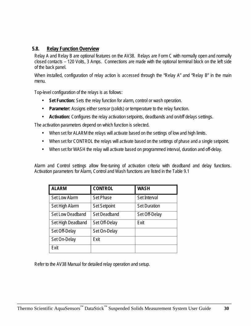
5.8. Relay Function Overview
Relay A and Relay B are optional features on the AV38. Relays are Form C with normally open and normally closed contacts – 120 Volts, 3 Amps. Connections are made with the optional terminal block on the left side of the back panel.
When installed, configuration of relay action is accessed through the “Relay A” and “Relay B” in the main menu. Top-level configuration of the relays is as follows:
• Set Function: Sets the relay function for alarm, control or wash operation.
• Parameter: Assigns either sensor (solids) or temperature to the relay function.
• Activation: Configures the relay activation setpoints, deadbands and on/off delays settings.
The activation parameters depend on which function is selected.
• When set for ALARM the relays will activate based on the settings of low and high limits.
• When set for CONTROL the relays will activate based on the settings of phase and a single setpoint.
• When set for WASH the relay will activate based on programmed interval, duration and off-delay.
Alarm and Control settings allow fine-tuning of activation criteria with deadband and delay functions. Activation parameters for Alarm, Control and Wash functions are listed in the Table 9.1
ALARM CONTROL WASH
Set Low Alarm Set Phase Set Interval
Set High Alarm Set Setpoint Set Duration
Set Low Deadband Set Deadband Set Off-Delay
Set High Deadband Set Off-Delay Exit
Set Off-Delay Set On-Delay
Set On-Delay Exit
Exit
Refer to the AV38 Manual for detailed relay operation and setup.

Thermo Scientific AquaSensors™
DataStick™
Suspended Solids Measurement System User Guide 31
6. AquaComm™ Interface
AquaComm™ is an application software package that runs on computers with Microsoft Windows 2000, XP or Vista operating systems. Refer to the USB Comms Adapter manual for installation and setup.
When the suspended solids sensor is connected AquaComm™ will automatically recognize the sensor type and display solids and temperature.
To calibrate, configure, diagnose or create data log files, select the pull-down menus.
Multiple AquaComm™ windows may be opened for as many unique communications ports that are supported on the computer.
7. Direct PLC Connections
When a suspended solids system is connected directly to a computer network, all measurement, calibration, configuration and diagnostic functions are accessible by any user interface that is also connected to the network.
Refer to the appropriate Thermo Scientific AquaSensors communications manual to set up an interface.
Modbus uses a register map of floating point, integer and ASCII measure, calibrate and configure commands.
Ethernet communications adapters allow access to all functions through Internet Explorer.
Devicenet and CANopen use an electronic file that is loaded for access to all functions.
Contact Thermo Fisher Scientific if assistance is needed in setting up an integrated interface to all DataStick measurement systems through a PLC network.

Thermo Scientific AquaSensors™
DataStick™
Suspended Solids Measurement System User Guide 32
8. Specification
Measurement
Range: 0 to 20,000 mg/l diatomaceous earth.
Resolution: 1 mg/l
Operational Environment
Water Temperature Range: -5°C to 50°C
Air Temperature Range: -20°C to 60°C
Power Requirements
Voltage Range: 24 VDC (90 to 240 VAC option)
Note: Class II DC power supply required
Construction
Sensor Head Material: Polycarbonate, Quartz Glass.
Weight: 1.2 lbs
Units of Measure
Measurement Units: mg/l, ppm, %
Temperature Units: °C, °F
Calibration
Sample (Span): 1 point
Zero: 1 point
Temperature: 1 point
NOTE: Factory calibration is done in Diatomaceous Earth. Solids with very different color
and particle size can be characterized at the factory.

Thermo Scientific AquaSensors™
DataStick™
Suspended Solids Measurement System User Guide 33
9. Suspended Solids Order Matrix and Accessories
Model Number RT2 Suspended Solids Measurement System. 0 to 20,000 mg/l Range. Polycarbonate sensor body. Fouling
Correction. Temperature measurement included. Precalibrated.
Back-Body and Comms Adapter Material 1 CPVC 1-Inch NPT
2 316 Stainless Steel 1-Inch NPT DataStick Communications 4 Modbus RTU. (Required for use with AV38 Local Display). 5 DeviceNet.
6 CANopen 7 Ethernet IP, Modbus TCP, TCP/IP. Connect to PoE Switch. RJ45 connector. 8 USB 10 foot cable with A type connector for use with PC and portable computers.
Cable Length 1 10 Feet 2 20 Feet 3 30 Feet
X Where X = Number of Feet/10
RT2
Local Interface Description (Standard Configurations) Part Number AV38 Display One 4-20mA output, PID. 24VDC.
Two 4-20mA outputs, PID, 2 Relays, Modbus Host, 24VDC. AV38BB0A1 AV38CB4A1
Mounting Hardware Description Part Number 1.5” Union Mount Stainless Steel
CPVC MH1041-RT MH1042-RT
Immersion Assembly 7 ft PVC extension with junction box – 1” Sensors MH3083
Immersion Assembly w/Swivel Rail Mounting
7 ft PVC extension with junction box – 1” Sensors With swivel hand rail mount.
MH1242
Immersion Assembly w/Swivel and Ball Float
7 ft PVC extension with junction box – 1” Sensors With swivel hand rail mount and inflatable float.
MH1252
1.5” Ball Valve Low Pressure, CPVC
Low Pressure, Stainless Steel High Pressure, CPVC High Pressure, Stainless Steel
MH1112
MH1111 MH1122 MH1121
Ball Float Platform PVC Float Platform for up to 4 DataSticks MHFB02
Wash Hardware Attach air/water purge block to sensor body. Works
with compressor & AV38 wash relay or PLC.
MH1222
Junction box Extension Cable
For extension cables. Terminal strip included. DataStick Extension cable
JBOXX01 DSECxx; xx=ft
Product Description Part Number Solids Calibration Kit Solids Powder Kit. Injector and 500ml mix bottle. SOLID01

Thermo Scientific AquaSensors™
DataStick™
Suspended Solids Measurement System User Guide 34
10. Limited Warranty
WARRANTY/REPLACEMENT PLAN
Thermo Fisher Scientific warrants its products against material and workmanship defect for a period of one year from the date of shipment. In the event that a defect is discovered during the warranty period, Thermo Fisher Scientific agrees, at its option, to repair or replace the defective product. Any product repaired or replaced under this warranty will be warranted only for the remainder of the original product warranty period. This warranty does not apply to consumable products associated with this product including, but not limited to, chemical reagents and salt bridges. Products may not be returned without authorization from Thermo Fisher Scientific. To obtain authorization, please call Thermo Fisher Scientific for a return material authorization number. Limitations: This warranty does not cover:
1. Damage caused by misuse, neglect (lack of appropriate maintenance), alteration, accident or improper application or installation.
2. Damage caused by any repair or attempted repair not authorized by Thermo Fisher Scientific. 3. Any product not used in accordance with the instructions furnished by Thermo Fisher Scientific. 4. Damage caused by acts of God, natural disaster, acts of war (declared or undeclared), acts of
terrorism, work actions, or acts of any governmental jurisdiction. 5. Freight charges to return merchandise to Thermo Fisher Scientific. 6. Travel fees associated with on-site warranty repair.
This warranty is the sole expressed warranty made by Thermo Fisher Scientific in connection with its products. All other warranties, whether expressed or implied, including without limitation, the warranties of merchantability and fitness for a particular purpose, are expressly disclaimed. The liability of Thermo Fisher Scientific shall be limited to the cost of the item giving rise to the claim. In no event shall Thermo Fisher Scientific be liable for incidental or consequential damages. This warranty is the sole and complete warranty for Thermo Fisher Scientific. No person is authorized to make any warranties or representations on behalf of Thermo Fisher Scientific. Thermo Fisher Scientific reserves the right to change or modify this warranty at any time.

Thermo Scientific AquaSensors™
DataStick™
Suspended Solids Measurement System User Guide 35
11. Terms and Conditions
Terms and Conditions of Sale
The following terms and conditions will be presumed acceptable unless changes are made in writing and accepted by both parties in a reasonable amount of time.
Any standard or boilerplate terms and conditions supplied with a written purchase order will not be applicable unless accepted in writing by both parties. Quotations: All quotations shall be in writing. Written quotations shall be valid for 30 days from the date issued. Verbal quotations or price lists are not valid. Pricing: All pricing is in US Dollars. Thermo Fisher Scientific reserves the right to change pricing without notice.
Terms: Payment terms are net 30 days from the date of invoice with approved credit. Thermo Fisher Scientific reserves the right to deny credit or revoke previously extended credit. Past due accounts are subject to interest charges. Other acceptable payment terms are cash, certified check, money order, credit card or letter of credit confirmed by any United States of America bank. Other payment terms are not valid unless accepted in writing.
Sales taxes shall be included on the invoice unless a valid tax exemption certificate is supplied.
Return Material Authorization: Contact Thermo Fisher Scientific Customer Service for a Return Material Authorization (RMA) number. Items returned without an RMA number will be rejected.
All returned merchandise must be in unused, resalable condition, and must not be contaminated with hazardous materials.
Cancelled orders must be returned within 30 days of the date on the invoice and shall be subject to expenses incurred that may include, but are not limited to, inspection and restocking fees. Items returned within 60 days shall be subject to a restocking charge that is equal to 15% of the purchase price. Items returned after more than 60 days shall be subject to a restocking charge equal to 25% of the purchase price. Thermo Fisher Scientific reserves the right to reject any return that is not under warranty after 60 days. Non-stock items are normally not returnable.
Transportation: Orders are shipped FOB Thermo Fisher Scientific, or factory, by the most efficient means available. Appropriate charges, such as freight and insurance will be added to invoices. All shipments will be insured. Goods damaged in shipment must be reported by the recipient to the freight carrier for claims.


Thermo Fisher Scientific
Environmental Instruments Process Water Instruments
North America 166 Cummings Center Beverly, MA 01915 USA Toll Free: 1-800-225-1480 Tel: 1-978-232-6000 Dom. Fax: 1-978-232-6015 Int’l Fax: 978-232-6031
EuropeP.O. Box 254, 3860 AG Nijkerk Wallerstraat 125K, 3862 BN Nijkerk, Netherlands Tel: (31) 033-2463887 Fax: (31) 033-2460832
Asia PacificBlk 55, Ayer Rajah Crescent #04-16/24, Singapore 139949 Tel: 65-6778-6876 Fax: 65-6773-0836
www.thermo.com/processwater
© 2009 Thermo Fisher Scientific Inc. All rights reserved.
258486-001 Rev. A 01-09