2428_pliquett
TRANSCRIPT

Offset-free bidirectional current source for impedance measurement
Uwe Pliquett, Markus Schönfeldt, Andreas Barthel, Dieter Frense, Thomas Nacke
Institut für Bioprozess- und Analysenmesstechnik e.V., Rosenhof D-37308 Heilbad Heiligenstadt, Germany
Abstract. In order to minimize the influence of electrode polarization and noise in impedance measurements, especially in the low frequency region, current injection shows several advantages compared to voltage application. Although the existence of a great variety of current sources, they meet our requirements only partially. We developed a voltage controlled current source for active front ends for a wide range of impedances, from Ω up to TΩ. A broad bandwidth from dc to 100 MHz was ensured by minimizing the parasitic capacitances. The current source outputs a symmetric signal without dc-offset. This is accomplished by a differential driver where the non-inverting branch was used for creating a current conveyor while the inverting branch host the feedback for offset control. We focused especially on the stability of the current source for usage with small metal electrodes in aqueous solutions.
1. Introduction Bioimpedance measurement is a simple and innocuous method for electrical characterization of biological matter [1;2]. Especially in the low frequency region from 100 Hz up to 10 MHz the behavior of the lipid membranes in cell structures dominate the impedance spectrum [3]. The impedance measurement in this frequency range employs either a voltage excitation of the material under test (MUT) and monitors the current through the material or vice versa. Other methods, like bridge calibration, are not considered here.
The theoretical background for electrodes with geometrical dimensions on the order of centimeters is teaching book material. Both, potentiostatic or galvanostatic excitation is well established and a great variety of devices for impedance measurement exist. However, if the same theory and the same devices are used in conjunction with microelectrodes, a departure from the expected results is often observed. The reason is the non-ideal behavior of the front end together with the usually neglected electrochemistry at the electrodes, even below the decomposition voltage. Often, any change in current density at the electrodes is not taken into account and parasitic elements at the input of the voltage monitor are neglected as well. Here we show how to circumvent these problems at least partially.
Besides using a voltage monitor with extremely high input impedance, a symmetrical current source for dc-offset free excitation can compensate asymmetric influences of the electrochemical reactions at the electrodes.
2. Electrode polarization In numerous applications the MUT is connected to the electronics via galvanically coupled electrodes. The most employed electrode materials are metals like iron (stainless steel), titanium, gold or platinum.

A double layer develops at the electrode-electrolyte interface [2]. At low frequencies, the impedance of this double layer has a similar magnitude as the impedance of the biological object. Any measurement done with two electrodes will result in the real impedance of the MUT plus the impedance of the electrodes. In order to overcome this, the four electrode interface, where an outer pair of electrodes is used for the application of the excitation signal (applicator electrodes) and the inner electrodes are used for monitoring the voltage dropping across the MUT (monitor electrodes) was introduced. In such an arrangement, any voltage dropping at the impedance of the applicator electrodes influences the measurement result only negligibly [4]. If the potential difference between both single monitor electrodes and the bulk electrolyte is equal, the measured voltage between the inner electrodes will truly be the voltage drop between the inner electrodes.
In this sense, it is quite unimportant whether a potentiostatic or galvanostatic excitation is used. As a matter of fact, even if neither, current nor voltage is controlled, impedance measurement would theoretically work just by measuring voltage and current.
When microelectrodes are used, the outer electrodes can influence the inner electrode by very close location. Moreover, due to the high curvature of such electrodes, local high field strength can overcome the limits for linearity resulting in harmonic distortion, even at low voltage. This means, especially for miniaturized electrodes with sharp geometry any change in the current density at the outer electrodes will influence the measured signal at the inner electrodes. Using a galvanostatic approach controls the current density and therefore prevents unpredictable interaction between applicator and monitor electrodes.
3. Current source for excitation It is generally accepted that excitation signals for bio-impedance measurements should be dc-offset free in order to minimize electrochemical effects at the material [5]. Offset free means that the time average of the signal is zero. Although the current through the current carrying electrodes is always complementary, even if one electrode is connected to ground, the voltage at the monitor electrodes may be very different (Fig.1a). This implies of course no shunting pathways to ground or any other potential, i.e. the MUT is electrically fully insulated from the environment. Although this sounds simple and clear, researchers often forget about hidden grounding or electrical connections when doing impedance measurements outside the laboratory.
RelMU
TR
el
Rel
Rel
+
-
UHI
ULO
Uappl
parasitic elements
t -1 -0.8 -0.6 -0.4 -0.2 0 0.2 0.4 0.6 0.8 1
-500
-400
-300
-200
-100
0
100
200
300
400
500
U / V
I / µ
A
Fig.1a. Input signal at the monitor electrodes due to the excitation by an offset free but not symmetrical signal. Although the input impedance of the difference amplifier is ideally infinite, parasitic elements yield an asymmetric current at the monitor electrodes, which disturbs dramatically the compensation of the electrode polarization for a tetra-polar interface. (b) Voltagram of a gold electrode of 1 cm² in contract with 100 mM KCl The potential drop between an electrode and the bulk electrolyte depends on the current density. Using cyclic voltammetry, reveals a small range, usually below 100 mV, where the electrode behaves linearly (Fig.1b). Exceeding this range, yields nonlinear behaviour of the electrode which generates harmonic distortion [6]. The influence of the double layer at the monitor electrodes can be partially compensated using a high symmetry of all signals with respect to ground. This yields the same electrode polarization at
a b
both monitor electrodes which is compensated by using the difference of both signals for further processing. This approach implies the usage of a symmetric excitation source, where the potential at the applicator electrodes is complementary with respect to ground. Moreover, a controlled current rather than the voltage yields lower distortion from the applicator electrodes.
4. Symmetric high bandwidth current source The symmetry of the applicator electrodes with respect to ground ensures the same time averaged speed and extent of electrochemical reactions at the voltage monitoring electrodes in tetrapolar applications.
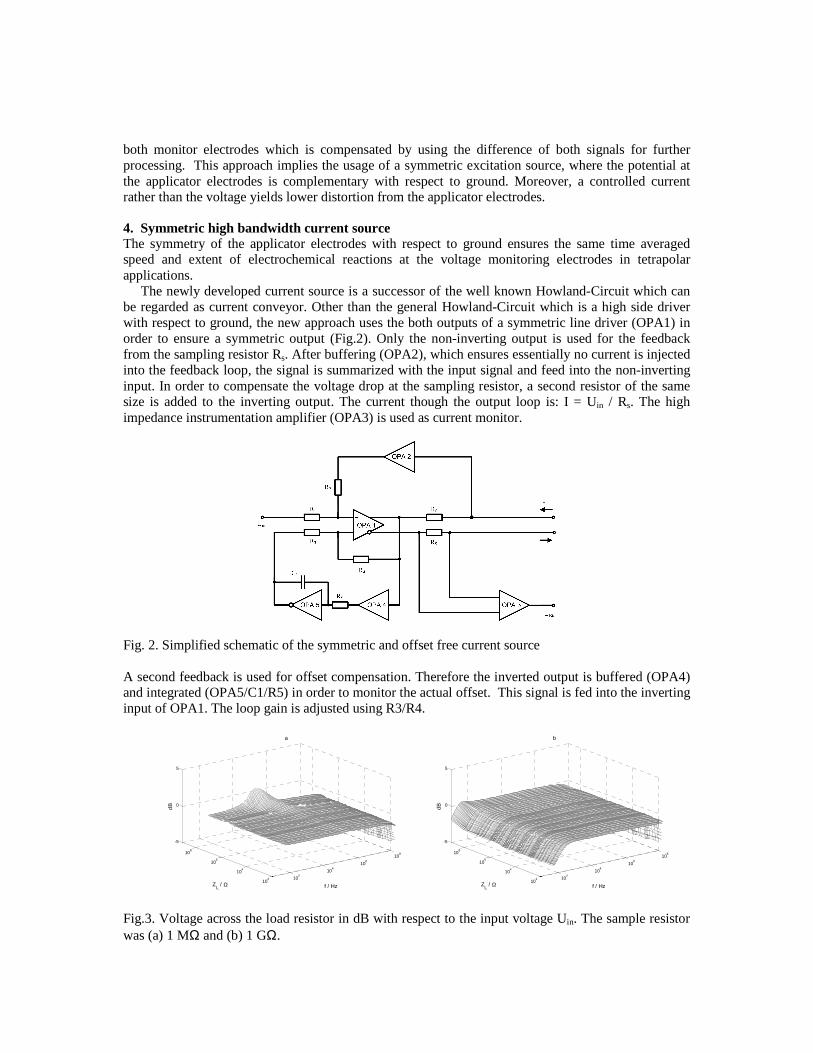
The newly developed current source is a successor of the well known Howland-Circuit which can be regarded as current conveyor. Other than the general Howland-Circuit which is a high side driver with respect to ground, the new approach uses the both outputs of a symmetric line driver (OPA1) in order to ensure a symmetric output (Fig.2). Only the non-inverting output is used for the feedback from the sampling resistor Rs. After buffering (OPA2), which ensures essentially no current is injected into the feedback loop, the signal is summarized with the input signal and feed into the non-inverting input. In order to compensate the voltage drop at the sampling resistor, a second resistor of the same size is added to the inverting output. The current though the output loop is: I = Uin / Rs. The high impedance instrumentation amplifier (OPA3) is used as current monitor.
Fig. 2. Simplified schematic of the symmetric and offset free current source A second feedback is used for offset compensation. Therefore the inverted output is buffered (OPA4) and integrated (OPA5/C1/R5) in order to monitor the actual offset. This signal is fed into the inverting input of OPA1. The loop gain is adjusted using R3/R4.
102
104
106
108
102
104
106
108
-5
0
5
f / Hz
a
ZL / Ω
dB
102
104
106
108
102
104
106
108
-5
0
5
f / Hz
b
ZL / Ω
dB
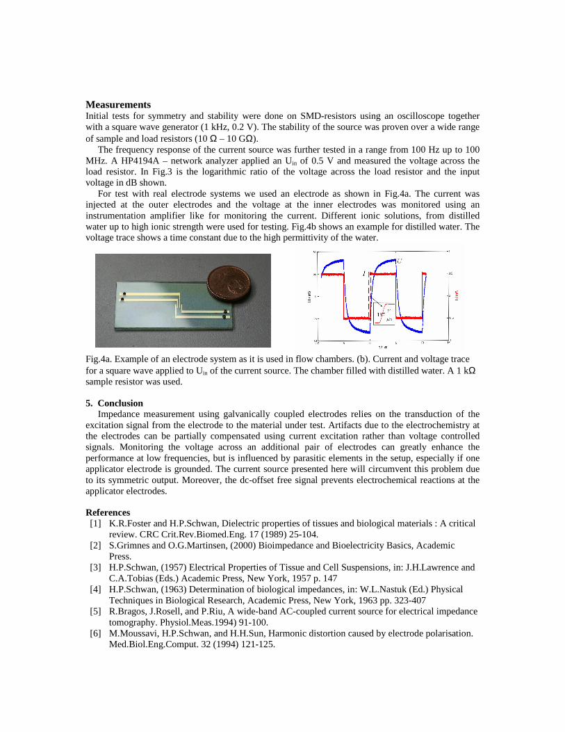
Fig.3. Voltage across the load resistor in dB with respect to the input voltage Uin. The sample resistor was (a) 1 MΩ and (b) 1 GΩ.
Measurements Initial tests for symmetry and stability were done on SMD-resistors using an oscilloscope together with a square wave generator (1 kHz, 0.2 V). The stability of the source was proven over a wide range of sample and load resistors (10 Ω – 10 GΩ).
The frequency response of the current source was further tested in a range from 100 Hz up to 100 MHz. A HP4194A – network analyzer applied an Uin of 0.5 V and measured the voltage across the load resistor. In Fig.3 is the logarithmic ratio of the voltage across the load resistor and the input voltage in dB shown.
For test with real electrode systems we used an electrode as shown in Fig.4a. The current was injected at the outer electrodes and the voltage at the inner electrodes was monitored using an instrumentation amplifier like for monitoring the current. Different ionic solutions, from distilled water up to high ionic strength were used for testing. Fig.4b shows an example for distilled water. The voltage trace shows a time constant due to the high permittivity of the water.
Fig.4a. Example of an electrode system as it is used in flow chambers. (b). Current and voltage trace for a square wave applied to Uin of the current source. The chamber filled with distilled water. A 1 kΩ sample resistor was used.
5. Conclusion Impedance measurement using galvanically coupled electrodes relies on the transduction of the
excitation signal from the electrode to the material under test. Artifacts due to the electrochemistry at the electrodes can be partially compensated using current excitation rather than voltage controlled signals. Monitoring the voltage across an additional pair of electrodes can greatly enhance the performance at low frequencies, but is influenced by parasitic elements in the setup, especially if one applicator electrode is grounded. The current source presented here will circumvent this problem due to its symmetric output. Moreover, the dc-offset free signal prevents electrochemical reactions at the applicator electrodes.
References [1] K.R.Foster and H.P.Schwan, Dielectric properties of tissues and biological materials : A critical
review. CRC Crit.Rev.Biomed.Eng. 17 (1989) 25-104. [2] S.Grimnes and O.G.Martinsen, (2000) Bioimpedance and Bioelectricity Basics, Academic
Press. [3] H.P.Schwan, (1957) Electrical Properties of Tissue and Cell Suspensions, in: J.H.Lawrence and
C.A.Tobias (Eds.) Academic Press, New York, 1957 p. 147 [4] H.P.Schwan, (1963) Determination of biological impedances, in: W.L.Nastuk (Ed.) Physical
Techniques in Biological Research, Academic Press, New York, 1963 pp. 323-407 [5] R.Bragos, J.Rosell, and P.Riu, A wide-band AC-coupled current source for electrical impedance
tomography. Physiol.Meas.1994) 91-100. [6] M.Moussavi, H.P.Schwan, and H.H.Sun, Harmonic distortion caused by electrode polarisation.
Med.Biol.Eng.Comput. 32 (1994) 121-125.