contents 2.4 demand supply gap this proposed plant at chhapra bahas, motihari-raxaul road, mothari,...
TRANSCRIPT
1
Contents
1.0 EXECUTIVE SUMMARY ........................................................................................ 3
2.0 INTRODUCTION OF THE PROJECT ..................................................................... 4
2.1 Identification of project & Project Proponent ........................................................... 4
2.2 Nature of Project ............................................................................................................ 4
2.3 Need of Project ............................................................................................................ 5
2.4 Demand Supply Gap .................................................................................................... 6
2.5 Employment generation ............................................................................................... 6
3.0 PROJECT DESCRIPTION ......................................................................................... 7
3.1 Type of Project ............................................................................................................ 7
3.2 Location........................................................................................................................ 7
3.3 Size or Magnitude of Operations. ................................................................................ 7
3.4 Project Description .................................................................................................... 10
3.5 Water, Energy/Power requirement ........................................................................... 15
3.6 Schematic Representative of feasibility drawing which give information of EIA
Purpose ................................................................................................................................... 19
4.0 SITE ANALYSIS .................................................................................................... 21
4.1 Connectivity ................................................................................................................ 21
4.2 Land Form, Land Use & Land ownership ............................................................... 21
4.3 Topography: ............................................................................................................... 21
4.4 Existing Land Use Pattern.......................................................................................... 21
4.5 Existing Infrastructure ................................................................................................ 22
4.6 Soil Classification ....................................................................................................... 22
4.7 Climatic Conditions: .................................................................................................. 22
4.8 Social infrastructure Available. ................................................................................. 22

2
5.0 PLANNING BRIEF ................................................................................................. 21
5.1 Planning concept ........................................................................................................ 21
5.2 Population projection ................................................................................................. 19
5.3 Land Use Planning .................................................................................................... 19
5.4 Assessment of infra structure Demand ...................................................................... 19
6.0 PROPOSE INFRASTRUCTURE ........................................................................... 19
6.1 Industrial Area (Processing Area) ........................................................................... 19
6.2 Residential Area (Non Processing Area) ................................................................. 19
6.3 Green Belt ................................................................................................................... 21
6.4 Social Infrastructure.................................................................................................. 20
6.5 Connectivity ............................................................................................................... 20
6.6 Drinking Water .......................................................................................................... 20
6.7 Sewage ........................................................................................................................ 20
6.8 Industrial Waste Management .................................................................................. 20
6.9 Power requirement .................................................................................................... 20
7.0 REHABITATION AND RESETTLEMENT (R & R) PLAN ............................ 21
8.0 PROJECT SCHEDULED AND PROJECT COST................................................. 21
9.0 ANALYSIS OF PROPOSAL (FINAL RECOMMENDATIONS)……………...23
3
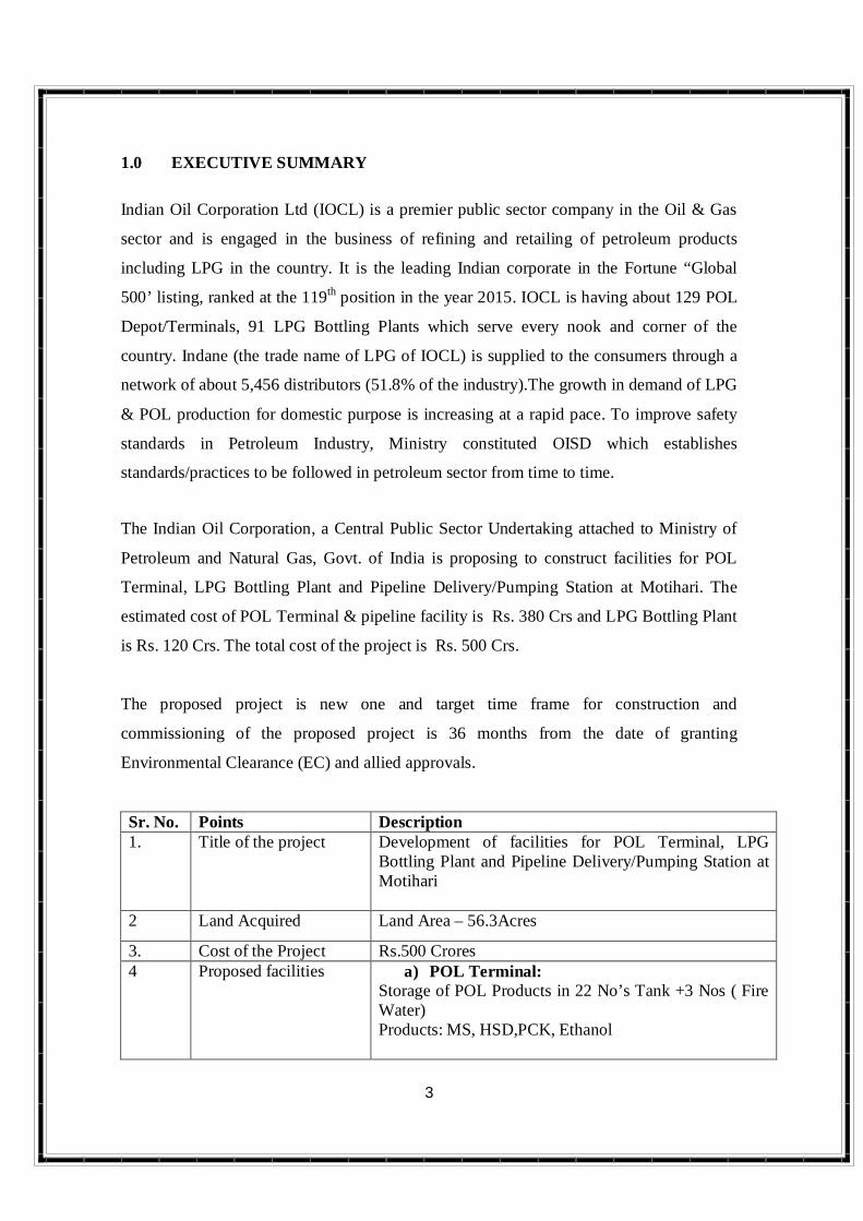
1.0 EXECUTIVE SUMMARY Indian Oil Corporation Ltd (IOCL) is a premier public sector company in the Oil & Gas
sector and is engaged in the business of refining and retailing of petroleum products
including LPG in the country. It is the leading Indian corporate in the Fortune “Global
500’ listing, ranked at the 119th position in the year 2015. IOCL is having about 129 POL
Depot/Terminals, 91 LPG Bottling Plants which serve every nook and corner of the
country. Indane (the trade name of LPG of IOCL) is supplied to the consumers through a
network of about 5,456 distributors (51.8% of the industry).The growth in demand of LPG
& POL production for domestic purpose is increasing at a rapid pace. To improve safety
standards in Petroleum Industry, Ministry constituted OISD which establishes
standards/practices to be followed in petroleum sector from time to time.
The Indian Oil Corporation, a Central Public Sector Undertaking attached to Ministry of
Petroleum and Natural Gas, Govt. of India is proposing to construct facilities for POL
Terminal, LPG Bottling Plant and Pipeline Delivery/Pumping Station at Motihari. The
estimated cost of POL Terminal & pipeline facility is Rs. 380 Crs and LPG Bottling Plant
is Rs. 120 Crs. The total cost of the project is Rs. 500 Crs.
The proposed project is new one and target time frame for construction and
commissioning of the proposed project is 36 months from the date of granting
Environmental Clearance (EC) and allied approvals.
Sr. No. Points Description 1. Title of the project Development of facilities for POL Terminal, LPG
Bottling Plant and Pipeline Delivery/Pumping Station at Motihari
2 Land Acquired Land Area – 56.3Acres
3. Cost of the Project Rs.500 Crores 4 Proposed facilities a) POL Terminal:
Storage of POL Products in 22 No’s Tank +3 Nos ( Fire Water) Products: MS, HSD,PCK, Ethanol

4
Sr. No. Points Description 2 X 8 Bay Bottom TLF Sheds
b) LPG Bottling Plant: 3 x 1200 MT MSVs 2x 24 Point Carousel 8 Bay TLD
c) Pipeline Station Delivery cum Pumping Station Pigging Facilities and other associated facilities
5 Storage Capacity LPG 3 x 1200 MT MT MSVs POL Products 76,215.6 KL - Present 39,359 KL - Future Sludge Tank 600 KL - Present
6. Proposed Air pollution Control measures
D.G. Sets will be provided with appropriated stack height and enclosures as per guidelines.
7 Water Requirement Operation Phase: 30 KLD (Domestic and Industrial i..e, cylinder washing, green belt etc) Source of Water: Bore Well / Panchyat
8 Waste Water Treatment Sewage Treatment Plant ETP – Cylinder Washing Oil Water Separator
9 Solid & Hazardous Waste Management and Disposal
Construction Phase: Waste oil : 100 LPM Unused batteries -6 nos per year, Used Lubricating oil : 60 Litre per month
10 Green Belt Adequate area has been earmarked for development of Green Belt.
2.0 INTRODUCTION OF THE PROJECT
2.1 Identification of project & Project Proponent
Indian Oil Corporation Limited (IOCL) proposes to construct POL Terminal, LPG
Bottling Plant & Pipeline Delivery, Pumping Sation at Chhapra Bahas, Motihari-
Raxaul Road, Mothari, East Champaran, Bihar to meet the needs of East
Champaran, West Champaran, Gopalganj and other adjoining districts as well as
for supplying petroleum products to Nepal Oil Corporation (NOC).
5
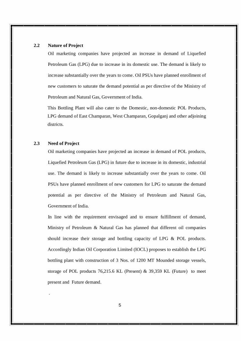
2.2 Nature of Project
Oil marketing companies have projected an increase in demand of Liquefied
Petroleum Gas (LPG) due to increase in its domestic use. The demand is likely to
increase substantially over the years to come. Oil PSUs have planned enrollment of
new customers to saturate the demand potential as per directive of the Ministry of
Petroleum and Natural Gas, Government of India.
This Bottling Plant will also cater to the Domestic, non-domestic POL Products,
LPG demand of East Champaran, West Champaran, Gopalganj and other adjoining
districts.
2.3 Need of Project
Oil marketing companies have projected an increase in demand of POL products,
Liquefied Petroleum Gas (LPG) in future due to increase in its domestic, industrial
use. The demand is likely to increase substantially over the years to come. Oil
PSUs have planned enrollment of new customers for LPG to saturate the demand
potential as per directive of the Ministry of Petroleum and Natural Gas,
Government of India.
In line with the requirement envisaged and to ensure fulfillment of demand,
Ministry of Petroleum & Natural Gas has planned that different oil companies
should increase their storage and bottling capacity of LPG & POL products.
Accordingly Indian Oil Corporation Limited (IOCL) proposes to establish the LPG
bottling plant with construction of 3 Nos. of 1200 MT Mounded storage vessels,
storage of POL products 76,215.6 KL (Present) & 39,359 KL (Future) to meet
present and Future demand.
.

6
2.4 Demand Supply Gap
This proposed plant at Chhapra Bahas, Motihari-Raxaul Road, Mothari, East
Champaran allotted by state government with the purpose of supplying
commercial and domestic LPG, POL products to the residents of East Champaran
and surrounding districts as well as for meeting needs of petroleum products of
Nepal.
2.5 Employment generation
There will be a positive impact in creation of direct and indirect employment
opportunities due to LPG Bottling Plant on local socio-economic profile.
Construction phase: Employment generation as contractual basis and
involvement of unskilled labor will be more.
Operation phase: Indirect Employment generation in handling of POL products,
cylinder, transportation of cylinder etc for skilled / semi-skilled labors and drivers.
Employment:
Regular Employees - 60 No’s
Contract Workers - 150 No’s
Security Staff - 40 No’s
7
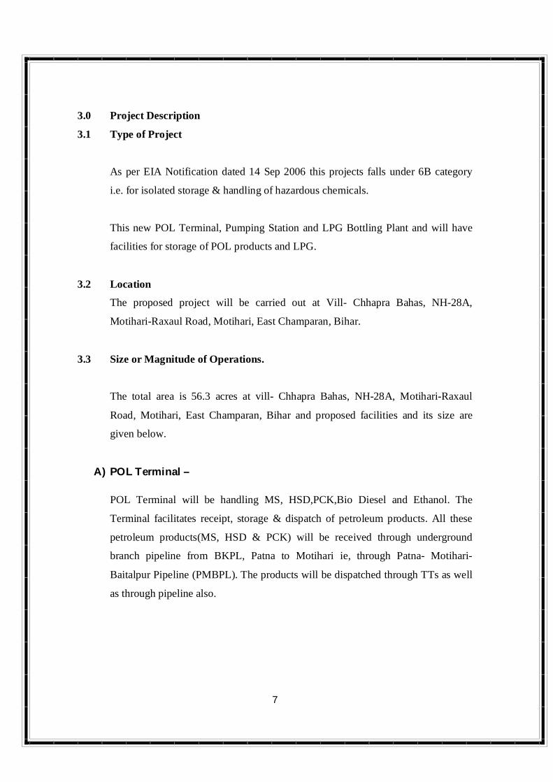
3.0 Project Description
3.1 Type of Project
As per EIA Notification dated 14 Sep 2006 this projects falls under 6B category
i.e. for isolated storage & handling of hazardous chemicals.
This new POL Terminal, Pumping Station and LPG Bottling Plant and will have
facilities for storage of POL products and LPG.
3.2 Location
The proposed project will be carried out at Vill- Chhapra Bahas, NH-28A,
Motihari-Raxaul Road, Motihari, East Champaran, Bihar.
3.3 Size or Magnitude of Operations.
The total area is 56.3 acres at vill- Chhapra Bahas, NH-28A, Motihari-Raxaul
Road, Motihari, East Champaran, Bihar and proposed facilities and its size are
given below.
A) POL Terminal – POL Terminal will be handling MS, HSD,PCK,Bio Diesel and Ethanol. The
Terminal facilitates receipt, storage & dispatch of petroleum products. All these
petroleum products(MS, HSD & PCK) will be received through underground
branch pipeline from BKPL, Patna to Motihari ie, through Patna- Motihari-
Baitalpur Pipeline (PMBPL). The products will be dispatched through TTs as well
as through pipeline also.

8
Following Storage tanks are proposed:
Product Tanks
Tank No. Size Class Type Product Cap. In
KL TK-1 24m (dia) x 20 m (ht) A IFR MS 9025
TK-2 24 m (dia) x 20 m (ht) A IFR MS 9025 TK-3 24 m (dia) x 20 m (ht) A IFR MS 9025 TK-4 14 m (dia) x 20 m (ht) B CR PCK 3071 TK-5 14 m (dia) x 20 m (ht). B CR PCK 3071 TK-6 28 m (dia) x 20 m (ht) B CR HSD 12284 TK-7 28 m (dia) x 20 m (ht). B CR HSD 12284 TK-8 28 m (dia) x 20 m (ht) B CR HSD 12284 TK-9 12 m (dia) x 14 m (ht) A IFR ETHANOL 1804 TK-10 12 m (dia) x 14 m (ht). A IFR ETHANOL 1804 TK-11 9 m (dia) x 10.5 m (ht) - CR BIO DIESEL 665 TK-12 3 m (dia) x 7.5 m (Long) B HOR HSD 53 TK-13 3 m (dia) x 7.5 m (Long) - HOR BIO DIESEL 53 TK-14 3 m (dia) x 7.5 m (Long) A HOR MS 53 TK-15 3 m (dia) x 7.5 m (Long) A HOR ETHANOL 53 TK-16 2.1 m (dia) x 6.25 m (Long) B HOR HSD 21.6 TK-17 10 m (dia) x 10.5 m (ht) A IFR TRANS MIX 820 TK-18 10 m (dia) x 10.5 m (ht) A IFR TRANS MIX 820
Other Tanks
Tank No. Size Class Type Product Cap. In
KL TK-19 8 m (dia) x 12 m (Long) - CR SLUDGE
TANK 600
9
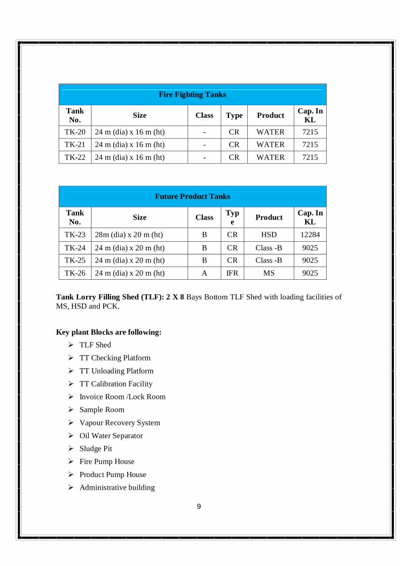
Fire Fighting Tanks
Tank No. Size Class Type Product Cap. In
KL TK-20 24 m (dia) x 16 m (ht) - CR WATER 7215 TK-21 24 m (dia) x 16 m (ht) - CR WATER 7215 TK-22 24 m (dia) x 16 m (ht) - CR WATER 7215
Future Product Tanks
Tank No. Size Class Typ
e Product Cap. In KL
TK-23 28m (dia) x 20 m (ht) B CR HSD 12284
TK-24 24 m (dia) x 20 m (ht) B CR Class -B 9025 TK-25 24 m (dia) x 20 m (ht) B CR Class -B 9025 TK-26 24 m (dia) x 20 m (ht) A IFR MS 9025
Tank Lorry Filling Shed (TLF): 2 X 8 Bays Bottom TLF Shed with loading facilities of MS, HSD and PCK.
Key plant Blocks are following: TLF Shed
TT Checking Platform
TT Unloading Platform
TT Calibration Facility
Invoice Room /Lock Room
Sample Room
Vapour Recovery System
Oil Water Separator
Sludge Pit
Fire Pump House
Product Pump House
Administrative building

10
S&D building.
PMCC
Control Room
B) LPG Bottling Plant
The main operation of this Bottling Plant is to receive bulk LPG, store into mounded
storage vessels, bottle in LPG cylinders and dispatch the same to distributors in east
champaran, west champaran, gopalganj and other adjoining districts.
There are mainly two operations:
Shed operation with 2 x 24 Point Carousel
TLD (Tank Truck Decantation) operation with 8 Bays
Shed operation is divided into following:
Filling Operation (Filling of LPG cylinders).
Evacuation operation (Evacuation of defective cylinders received from Market).
Cold repair ( Replacement of defective Valve with new one)
Degassing operation (Degassing of defective cylinder)
Statutory Testing of out dated cylinder
In TLD operation, we receive product i.e. LPG through tank truck from Barauni, Haldia
and Paradip based on availability and transfer into three Mounded Storage Vessels (3 X
1200 MT Mounded Storage Bullets).
Provision of pipeline Tap off point (TOP) for connection through Paradip- Haldia-
Durgapur-Patna-Muzaffarpur LPG Pipeline is also to be made.
Key plant Blocks are following: Empty Cum Filling shed.
Filled shed.
Valve change shed

11
Statutory Testing Plant
Product pump house.
TLD
Mounded Storage Vessels area.
Administrative building
S&D building.
Fire Pump House. PMCC
C) Pipeline Station –
As per PMBPL Project, a delivery cum pumping station is to be set up at Motihari.
Storage Tanks at Motihari Terminal will be used for product receipt ex PMBPL as
well as for pumping into Motihari Amlekhgunj Pipeline.
2 Trans Mix tanks of capacity 820 KL each connected to pipeline delivery
facilities to be constructed.
Main line pumps.
Pigging facilities.
HT station.
D) Common facilities –
Administrative Building
Fire fighting facilities
Electrical sub-station
Canteen
Worker amenity block
TT Parking area

12
E) Other Facilities – Laboratory
Rain Water Harvesting
Security System
Communication through PA/Paging System and VHF hand sets
First Aid Room
Google Image of 10 Km Radius

13
3.4 Project Description
There will be no chemical process involved and the operation carried out will be
receipt of POL Products & LPG in bulk and will be distributed to customers of
surrounding districts.
POL Products:
POL products will be received through underground branch pipeline from BKPL,
Patna to Motihari through Patna- Motihari- Baitalpur Pipeline (PMBPL). The
products will be dispatched through TTs as well as through pipeline also.
LPG Bottling Plant:
LPG in Bulk form in road tankers, storage in mounded bullets and filling of LPG
into cylinders using carousel and associated systems. The cylinders filled will be
checked for quality and then dispatched by Cylinder stake Trucks.
The process involved can be divided into 4 Stages:
Receipt of finished LPG products through bullet trucks.
Storage of LPG products in storage tanks as per OISD norms. Packaging of the LPG into cylinders.
Dispatch of LPG products through Stake Trucks
LPG BULK STORAGE
It is now proposed to construct 3 No’s 1200MT capacity Mounded Storage Vessel
which will be constructed/fabricated to the stringent Oil Industry Safety
Directorate’s OISD norms and BS standards. There will be only one LPG liquid
nozzle through which LPG shall be received and discharged from each bullet.

14
FIRE FIGHTING &SAFETY FACILITIES
All facilities will be having fire fighting facilities as per OISD 144, OISD 150 and
relevant IS codes.
The main components of the fire water system are:
Fire Water Storage
Fire Water Pumps
Water Sprinkler/ Deluge system.
Fire water distribution piping network inclusive of Hydrant/ Monitor
Flow Rate Design:
Medium Velocity sprinkler system with automatic heat detection having remote/
local operated Deluge valve with spray density of Minimum 10.2 LPM/ Sq.M are
provided at all facilities excluding LPG Pump house (i.e., storage Vessels,
Cylinder Storage/ Filling/ Repair Sheds, TLD) where as LPG Pump house is
provided with 20.4 LPM/ Sq.M.
The fire water system in the plant designed to meet the highest fire water flow
requirement of a single largest risk i.e., Filling Shed water requirement plus 288
KL/Hr
Fire Water Storage:
Total three numbers of fire water tanks with capacity of 21,645KL each.
Total fire water storage = 7,215 KL
Safety Relief System: Relief system adequately designed and provided as per OISD 144 / OISD150
guidelines. Two 100% Safety relief valves are provided on each vessel, each relief
valve having the required design, relieving capacity. Other relief valves (for
compressor, for trapped liquid between blocks etc.) are routed locally but to safe
location.
15
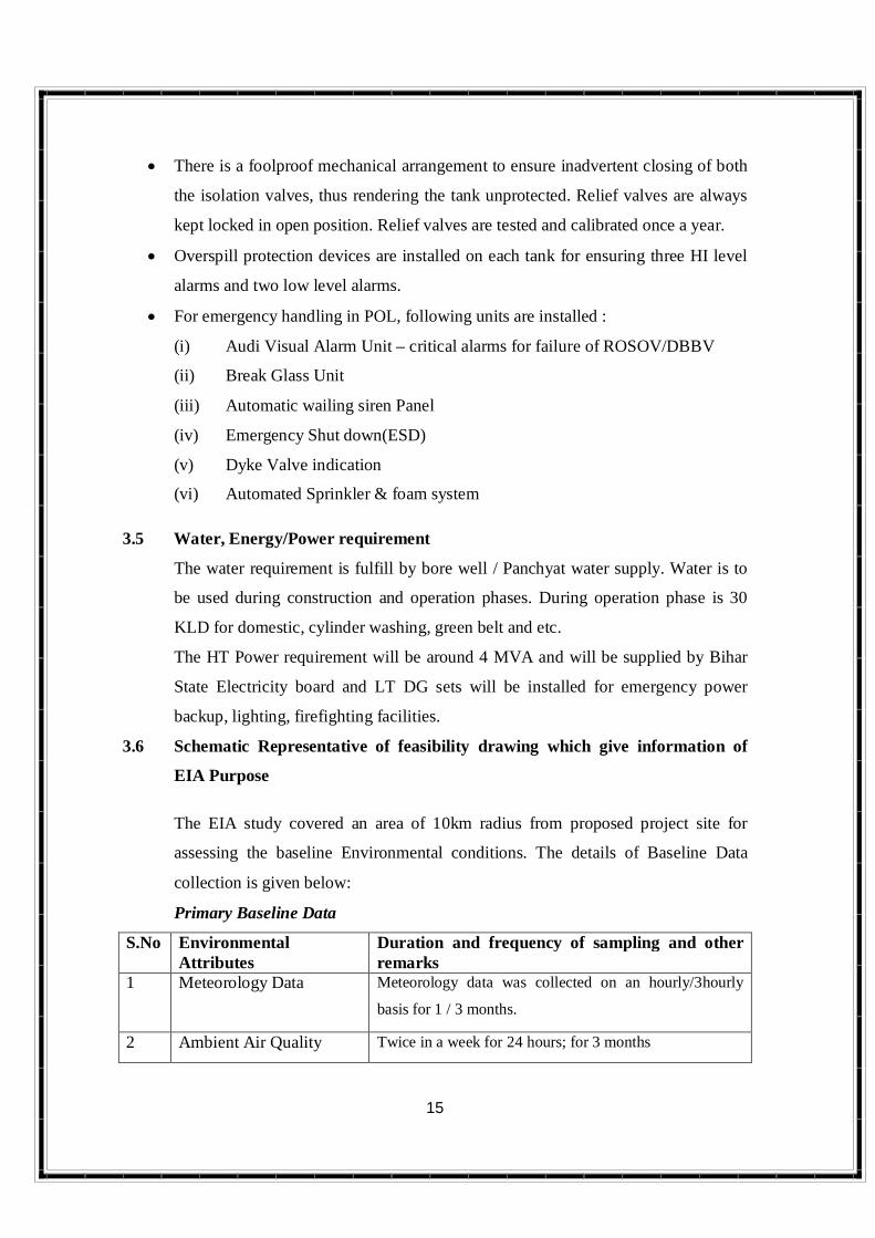
There is a foolproof mechanical arrangement to ensure inadvertent closing of both
the isolation valves, thus rendering the tank unprotected. Relief valves are always
kept locked in open position. Relief valves are tested and calibrated once a year.
Overspill protection devices are installed on each tank for ensuring three HI level
alarms and two low level alarms.
For emergency handling in POL, following units are installed :
(i) Audi Visual Alarm Unit – critical alarms for failure of ROSOV/DBBV
(ii) Break Glass Unit
(iii) Automatic wailing siren Panel
(iv) Emergency Shut down(ESD)
(v) Dyke Valve indication
(vi) Automated Sprinkler & foam system
3.5 Water, Energy/Power requirement
The water requirement is fulfill by bore well / Panchyat water supply. Water is to
be used during construction and operation phases. During operation phase is 30
KLD for domestic, cylinder washing, green belt and etc.
The HT Power requirement will be around 4 MVA and will be supplied by Bihar
State Electricity board and LT DG sets will be installed for emergency power
backup, lighting, firefighting facilities.
3.6 Schematic Representative of feasibility drawing which give information of
EIA Purpose
The EIA study covered an area of 10km radius from proposed project site for
assessing the baseline Environmental conditions. The details of Baseline Data
collection is given below:
Primary Baseline Data
S.No Environmental Attributes
Duration and frequency of sampling and other remarks
1 Meteorology Data Meteorology data was collected on an hourly/3hourly
basis for 1 / 3 months.
2 Ambient Air Quality Twice in a week for 24 hours; for 3 months
16
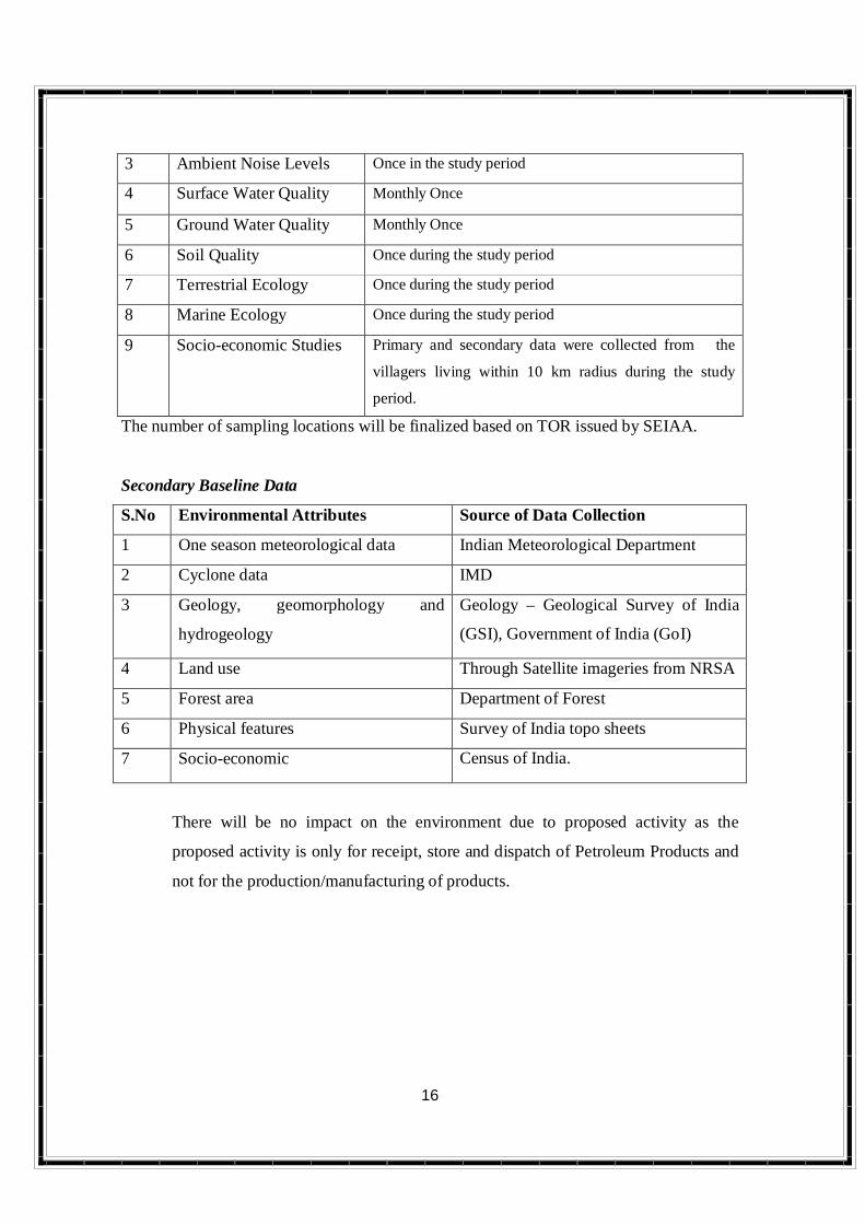
3 Ambient Noise Levels Once in the study period
4 Surface Water Quality Monthly Once
5 Ground Water Quality Monthly Once
6 Soil Quality Once during the study period
7 Terrestrial Ecology Once during the study period
8 Marine Ecology Once during the study period
9 Socio-economic Studies Primary and secondary data were collected from the
villagers living within 10 km radius during the study
period.
The number of sampling locations will be finalized based on TOR issued by SEIAA.
Secondary Baseline Data
S.No Environmental Attributes Source of Data Collection
1 One season meteorological data Indian Meteorological Department
2 Cyclone data IMD
3 Geology, geomorphology and
hydrogeology
Geology – Geological Survey of India
(GSI), Government of India (GoI)
4 Land use Through Satellite imageries from NRSA
5 Forest area Department of Forest
6 Physical features Survey of India topo sheets
7 Socio-economic Census of India.
There will be no impact on the environment due to proposed activity as the
proposed activity is only for receipt, store and dispatch of Petroleum Products and
not for the production/manufacturing of products.

17
4.0 Site Analysis
4.1 Connectivity
Plant is adjacent to national highway NH-28A. Nearest railway station is semra
railway station at a distance 1 km approximately.
4.2 Land Form, Land Use & Land ownership
Proposed project site was acquired from Government.
4.3 Topography:
In general the district exhibits a high to low land with few gentle undulations. The
drainage system of the district is controlled by the river Gandak, Burhi Gandak &
Baghmati & its tributaries.
The total area of land for cultivation is 303923 hectare. Irrigation facilities to
176115 hectare of land are available in the district while area under non irrigation
is 127808 hectare The district receives a normal rainfall of 1241.6 mm . The
economy of the district mainly depends upon agriculture. It has seen several ups
and downs perpetuated by Baghmati in the form of flood, famine and drought.
Flood and drought have remained the regular feature of the area.
Source: MSME district industrial profile.
4.4 Existing Land Use Pattern
Present land use based on remote sensing satellite imageries were collected from
NRSA Bhuvan. However, in preparation LU/LC will be made using latest satellite
imaginary for 10 KM radius of the project site during preparation of EIA. .
18
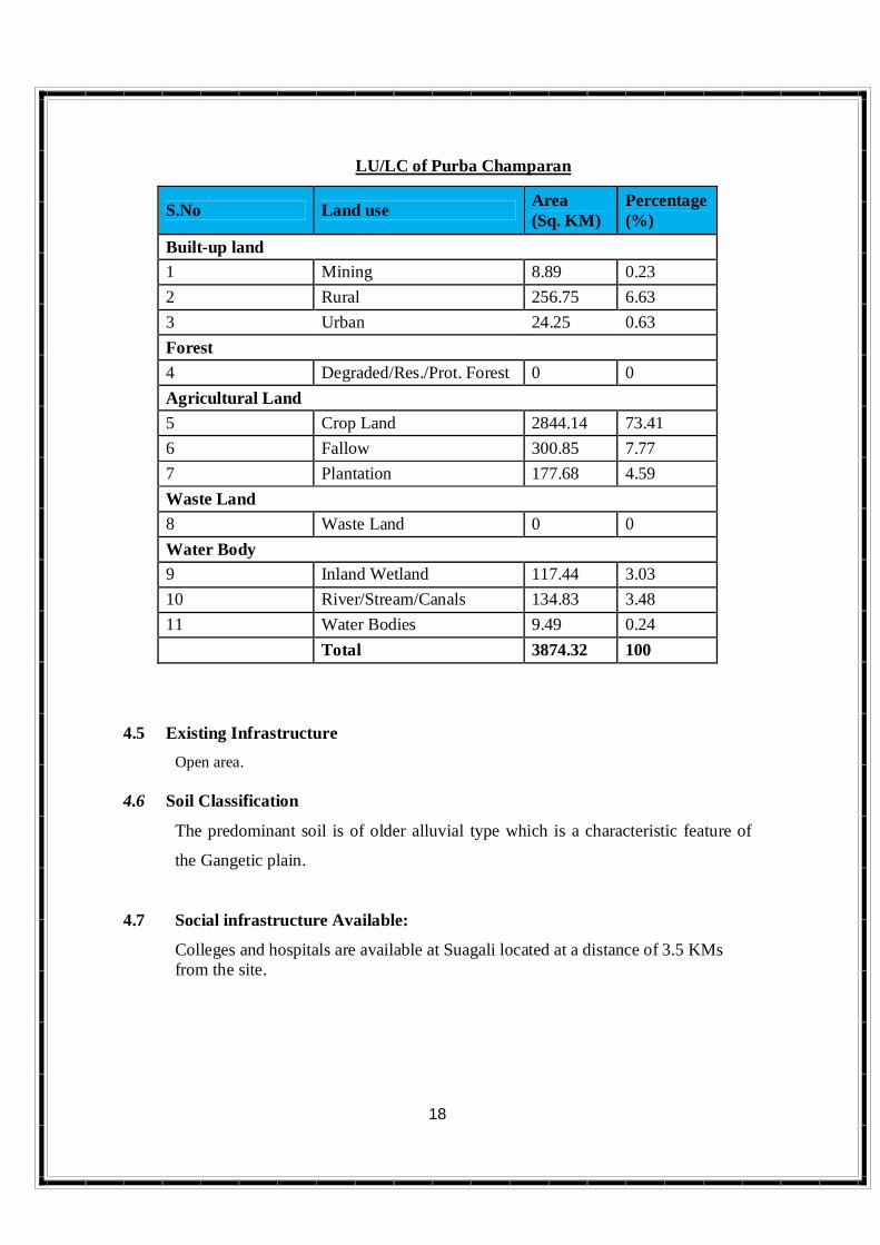
LU/LC of Purba Champaran
S.No Land use Area (Sq. KM)
Percentage (%)
Built-up land 1 Mining 8.89 0.23 2 Rural 256.75 6.63 3 Urban 24.25 0.63 Forest 4 Degraded/Res./Prot. Forest 0 0 Agricultural Land 5 Crop Land 2844.14 73.41 6 Fallow 300.85 7.77 7 Plantation 177.68 4.59 Waste Land 8 Waste Land 0 0 Water Body 9 Inland Wetland 117.44 3.03 10 River/Stream/Canals 134.83 3.48 11 Water Bodies 9.49 0.24 Total 3874.32 100
4.5 Existing Infrastructure Open area. 4.6 Soil Classification
The predominant soil is of older alluvial type which is a characteristic feature of
the Gangetic plain.
4.7 Social infrastructure Available:
Colleges and hospitals are available at Suagali located at a distance of 3.5 KMs from the site.

19
5.0 Planning brief
5.1 Planning concept
IOCL Plan for the following: POL Products Storage: POL Products - 22 no’s tanks Sludge - 1 no’s Fire Water - 3 no’s POL loading in 2 x 8 no’s TLF Shed
Brief Description of facilities
No of Bullets 3 x 1200 MT No. of TLD bays 8
5.2 Population projection
The proposed project does not envisage any displacement of population and no
resettlement of population as the land acquired from State Govt is a barren land on
which no population resides.
5.3 Land Use Planning
The total area of the plant is 56.3 Acre.
5.4 Assessment of infrastructure Demand
Infrastructure required for the proposed storage will be constructed. The
development shall only lead to positive impact on infrastructure and services.
6.0 Proposed infrastructures
6.1 Industrial Area (Processing Area)
Proposed infrastructure will construct at chhapra bahas, Motihari, East Champaran.
6.2 Residential Area (Non Processing Area)
IOCL is not proposing to construct any residential facility for proposed project at
the site.

20
6.3 Green Belt
Around border of the LPG bottling plant, POL Terminal and Pumping Facilities,
green belt will be maintained.
6.4 Social Infrastructure
The proposed site is well connected with road network to village and Mandal
head quarters.
6.5 Connectivity
The proposed site is well connected with black top roads.
6.6 Drinking Water
Drinking water will be from bore well / panchyat of 30 KLD for Domestic and
Washings during operation phase.
6.7 Sewage
The maximum water consumption will be 16.25 KLD of which 13 KLD will be
waste water generated and will be treated and used for green belt.
6.8 Industrial Waste Management
In the proposed POL Terminal & LPG Bottling plant, there is no generation of
Solid/Liquid waste. LPG will be stored in mounded bullet. Only waste which can
be recycled, terminal sweepings & viz. and hazardous waste, used batteries and
used lubricating oil.
6.9 Power requirement
It will be met through Bihar State Electricity Board.
21
7.0 Rehabilitation and Resettlement (R & R) Plan
The proposed facility does not envisage any displacement of population and no
resettlement of population as the plot taken from State Govt. has no population.
Hence there is no impact on this account.
8.0 Project Scheduled and Project Cost.
The total cost of the Project is Rs.500 Crore which is scheduled to be completed in
thirty six months from the date of EC from SEIAA and other allied clearance.
9.0 Analysis of Proposal (Final Recommendations)
There will be creation of indirect employment opportunities to the local people due
to construction of POL Terminal & LPG Bottling Plant.

22
PRE-FEASIBILITY REPORT
FOR
DEVELOPMENT OF POL TERMINAL, LPG
BOTTLING PLANT AND PIPELINE DELIVERY/
PUMING STATION
AT NH-28A, CHHAPRA BAHAS, MOTIHARI, EAST CHAMPARAN, MOTIHARI, BIHAR.
Submitted by
M/s. SV ENVIRO LABS & CONSULTANTS ENVIRO HOUSE, BLOCK-B, B-1, IDA, AUTONAGAR,
VISAKHAPATNAM (Dt), ANDHRA PRADESH QCI No: 140, MoEF & NABL Recognized Laboratory