24. antennas - brown university · what is an antenna types of antennas reciprocity hertzian dipole...
TRANSCRIPT
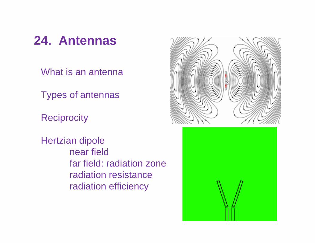
What is an antenna
Types of antennas
Reciprocity
Hertzian dipolenear fieldfar field: radiation zoneradiation resistanceradiation efficiency
24. Antennas
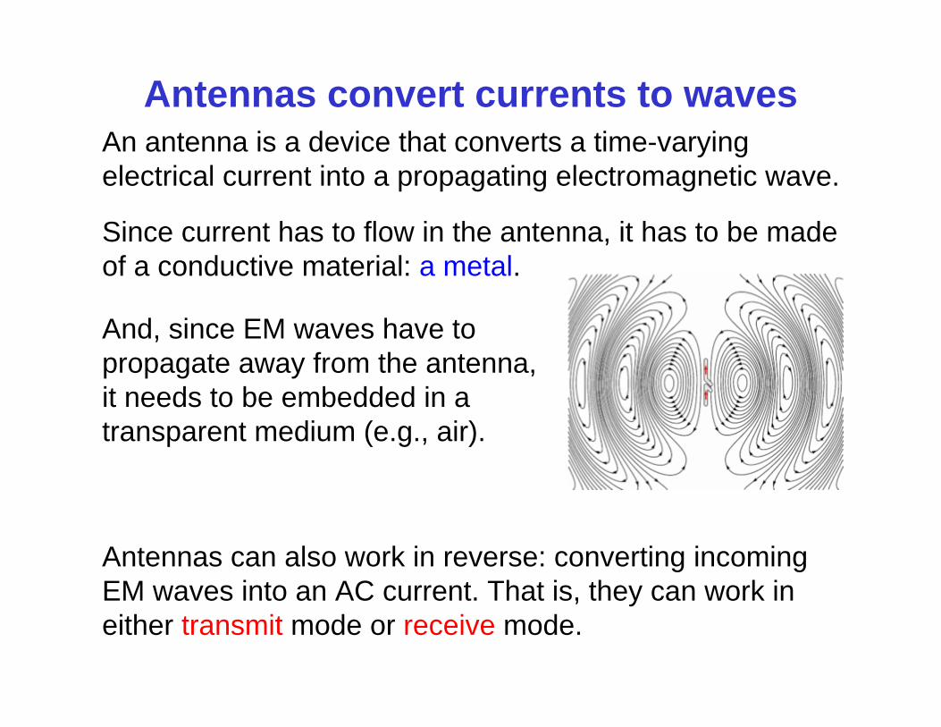
Antennas convert currents to wavesAn antenna is a device that converts a time-varying electrical current into a propagating electromagnetic wave.
Since current has to flow in the antenna, it has to be made of a conductive material: a metal.
And, since EM waves have to propagate away from the antenna, it needs to be embedded in a transparent medium (e.g., air).
Antennas can also work in reverse: converting incoming EM waves into an AC current. That is, they can work in either transmit mode or receive mode.
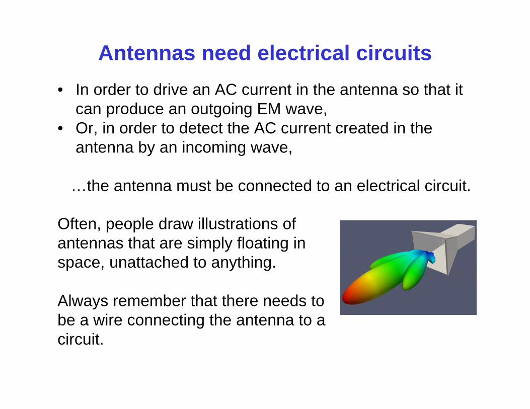
Antennas need electrical circuits• In order to drive an AC current in the antenna so that it
can produce an outgoing EM wave,• Or, in order to detect the AC current created in the
antenna by an incoming wave,
…the antenna must be connected to an electrical circuit.
Often, people draw illustrations of antennas that are simply floating in space, unattached to anything.
Always remember that there needs to be a wire connecting the antenna to a circuit.
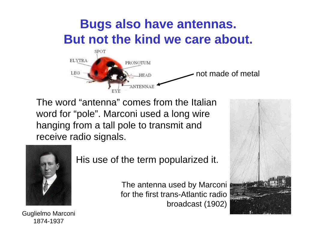
Bugs also have antennas. But not the kind we care about.
The word “antenna” comes from the Italian word for “pole”. Marconi used a long wire hanging from a tall pole to transmit and receive radio signals.
His use of the term popularized it.
The antenna used by Marconi for the first trans-Atlantic radio
broadcast (1902)Guglielmo Marconi
1874-1937
not made of metal
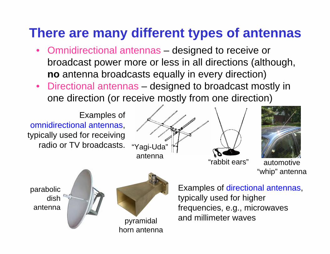
There are many different types of antennas
Examples of directional antennas, typically used for higher frequencies, e.g., microwaves and millimeter wavespyramidal
horn antenna
parabolic dish
antenna
“Yagi-Uda”antenna
Examples of omnidirectional antennas,
typically used for receiving radio or TV broadcasts.
“rabbit ears” automotive “whip” antenna
• Omnidirectional antennas – designed to receive or broadcast power more or less in all directions (although, no antenna broadcasts equally in every direction)
• Directional antennas – designed to broadcast mostly in one direction (or receive mostly from one direction)
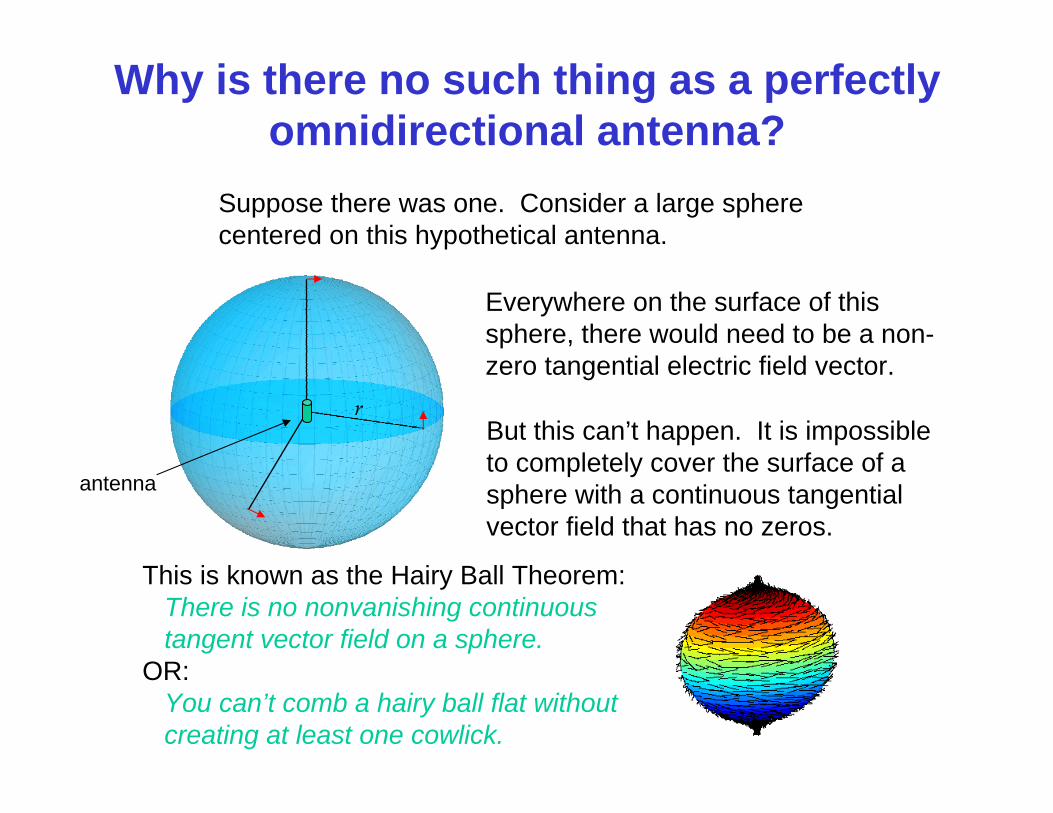
Why is there no such thing as a perfectly omnidirectional antenna?
Suppose there was one. Consider a large sphere centered on this hypothetical antenna.
Everywhere on the surface of this sphere, there would need to be a non-zero tangential electric field vector.
antenna
But this can’t happen. It is impossible to completely cover the surface of a sphere with a continuous tangential vector field that has no zeros.
This is known as the Hairy Ball Theorem:There is no nonvanishing continuous tangent vector field on a sphere.
OR:You can’t comb a hairy ball flat without creating at least one cowlick.
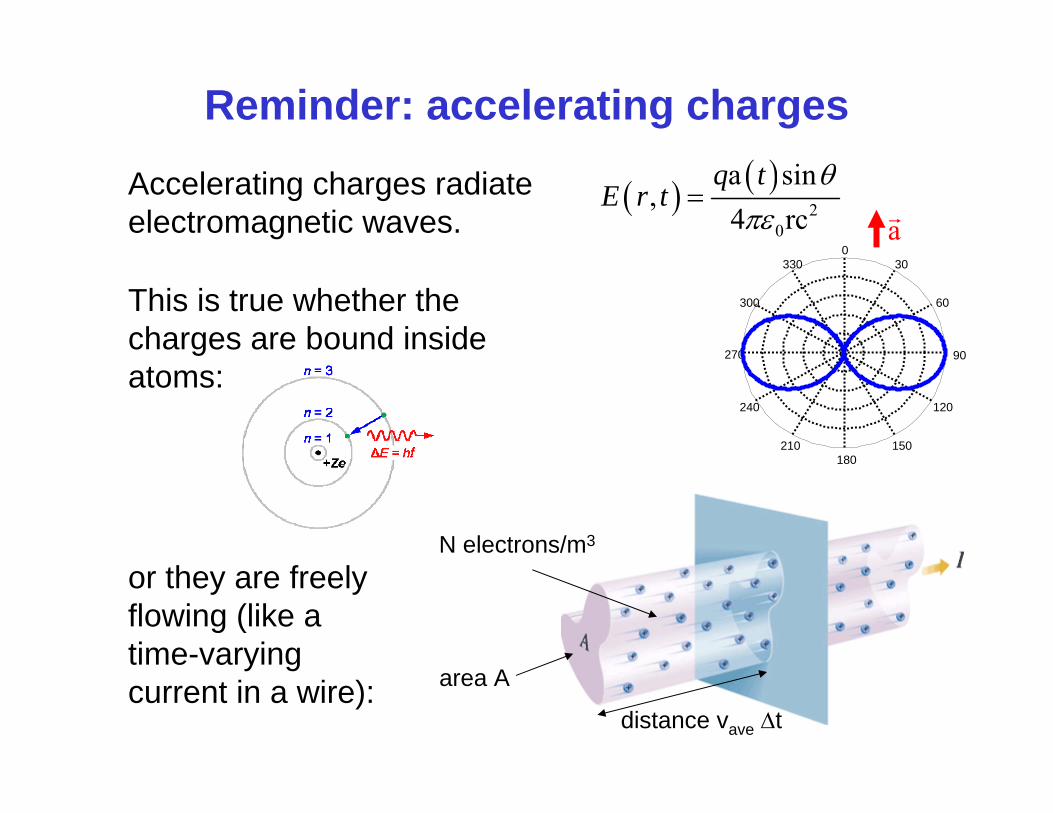
Reminder: accelerating charges
60
240
30
210
0
180
330
150
300
120
270 90
aAccelerating charges radiate electromagnetic waves.
2
0
a sin,
4 rc
q tE r t
or they are freely flowing (like a time-varying current in a wire): area A
N electrons/m3
distance vave t
This is true whether the charges are bound inside atoms:
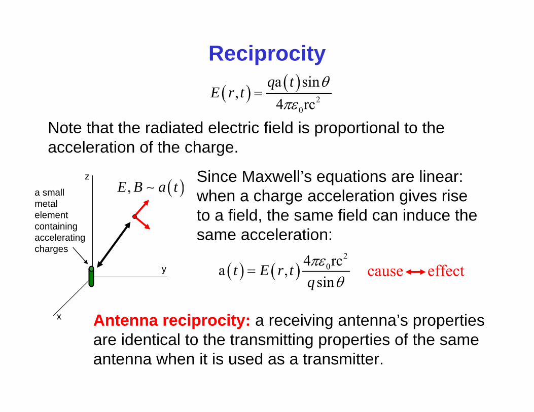
Reciprocity
Note that the radiated electric field is proportional to the acceleration of the charge.
Since Maxwell’s equations are linear: when a charge acceleration gives rise to a field, the same field can induce the same acceleration:
Antenna reciprocity: a receiving antenna’s properties are identical to the transmitting properties of the same antenna when it is used as a transmitter.
2
0
a sin,
4 rc
q tE r t
a small metal element containing accelerating charges
2
04 rca ,sin
t E r tq
cause effecty
x
z ,E B a t
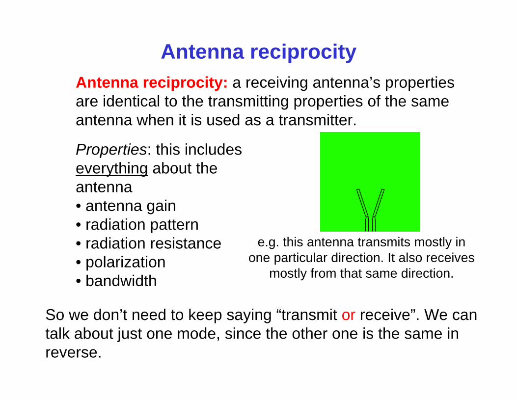
Antenna reciprocityAntenna reciprocity: a receiving antenna’s properties are identical to the transmitting properties of the same antenna when it is used as a transmitter.
So we don’t need to keep saying “transmit or receive”. We can talk about just one mode, since the other one is the same in reverse.
Properties: this includes everything about the antenna• antenna gain• radiation pattern• radiation resistance• polarization• bandwidth
e.g. this antenna transmits mostly in one particular direction. It also receives
mostly from that same direction.
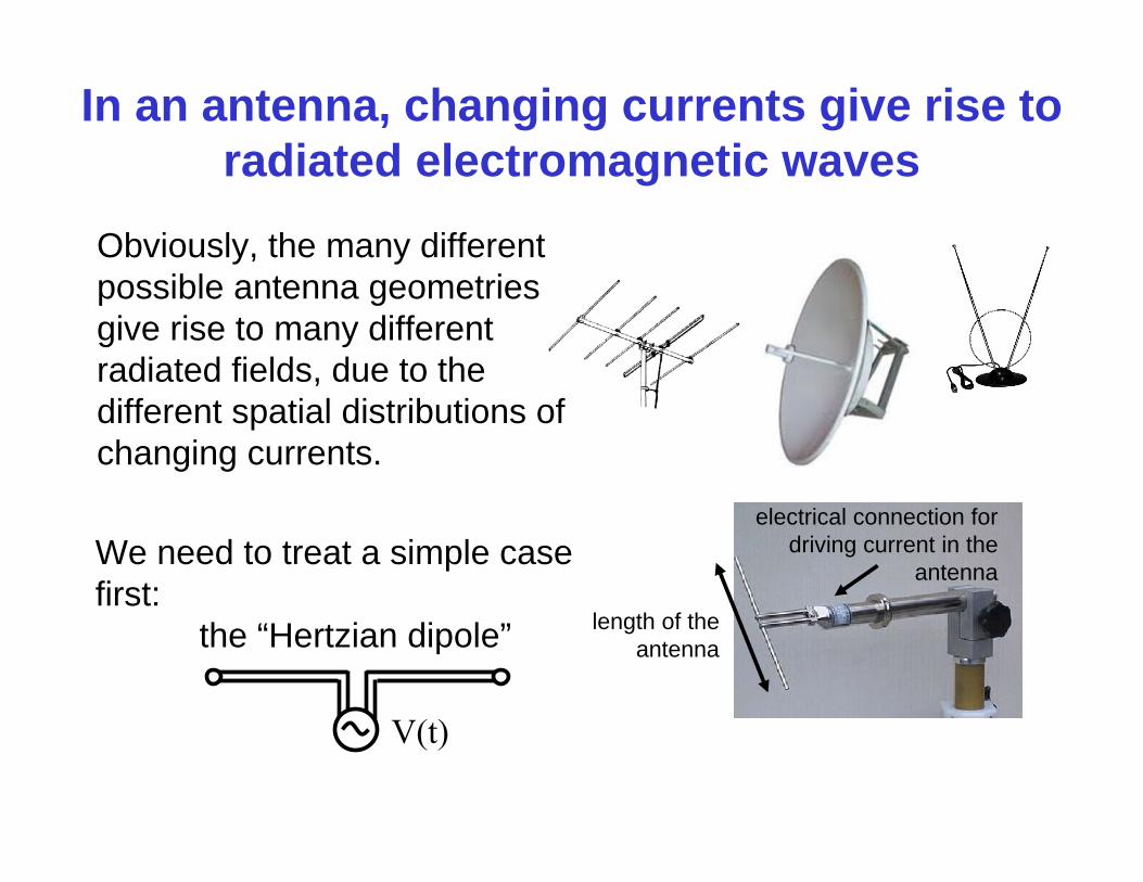
In an antenna, changing currents give rise to radiated electromagnetic waves
Obviously, the many different possible antenna geometries give rise to many different radiated fields, due to the different spatial distributions of changing currents.
length of the antenna
electrical connection for driving current in the
antenna
V(t)
We need to treat a simple case first:
the “Hertzian dipole”
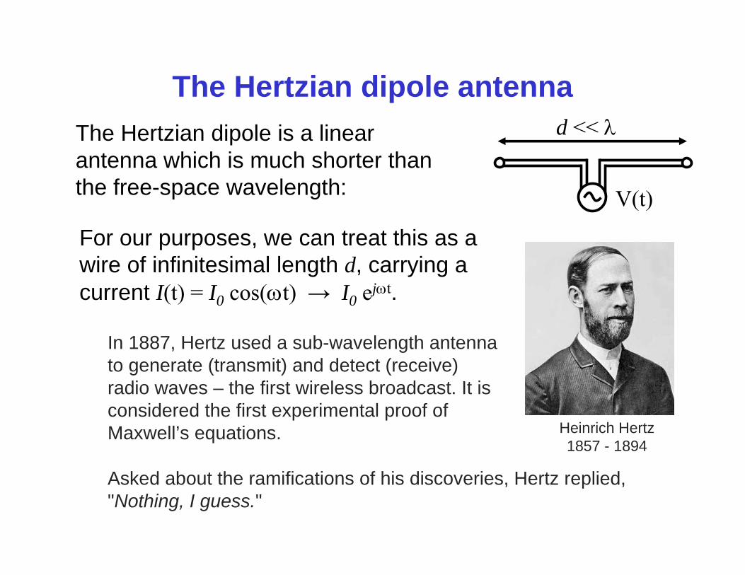
The Hertzian dipole antenna
V(t)
d << The Hertzian dipole is a linear antenna which is much shorter than the free-space wavelength:
In 1887, Hertz used a sub-wavelength antenna to generate (transmit) and detect (receive) radio waves – the first wireless broadcast. It is considered the first experimental proof of Maxwell’s equations. Heinrich Hertz
1857 - 1894
Asked about the ramifications of his discoveries, Hertz replied,"Nothing, I guess."
For our purposes, we can treat this as a wire of infinitesimal length d, carrying a current I(t) = I0 cos(t) → I0 ejt.
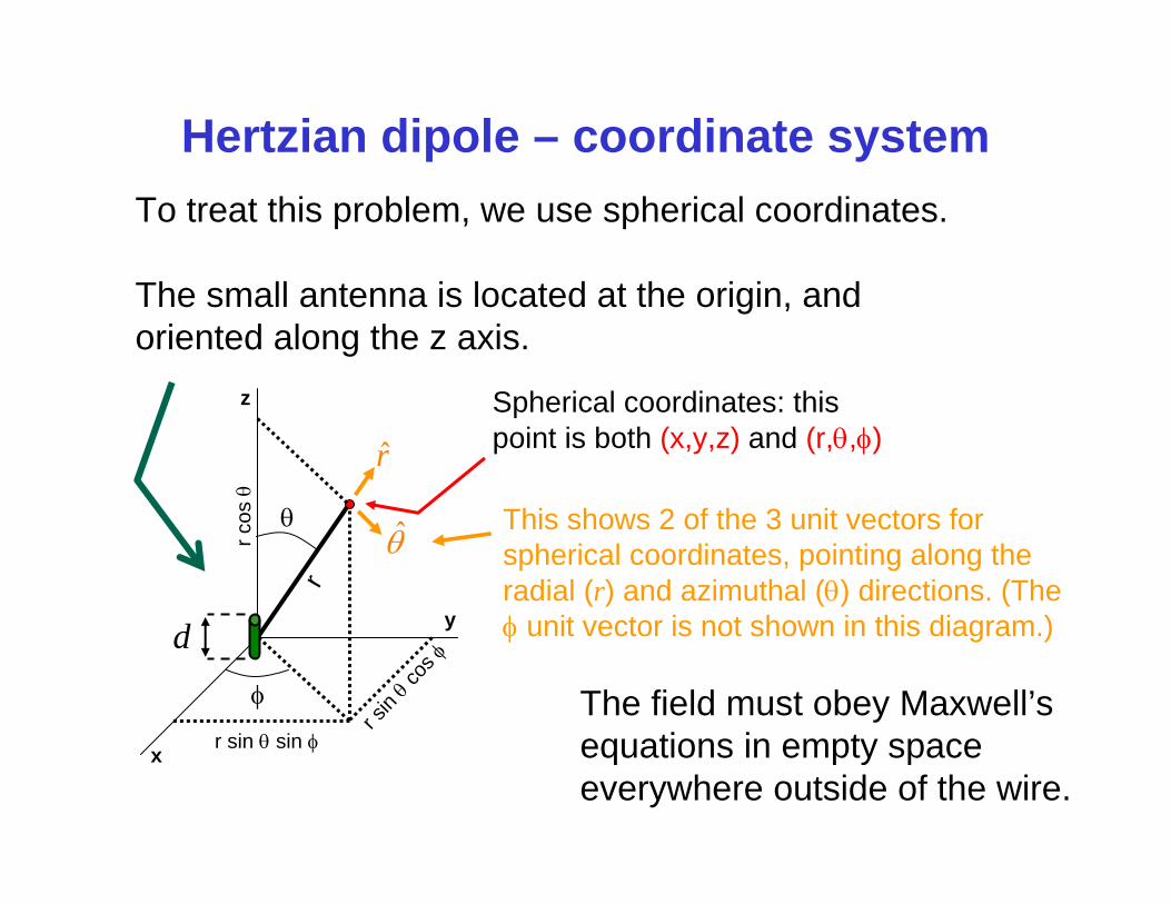
Hertzian dipole – coordinate system
Spherical coordinates: this point is both (x,y,z) and (r,,)
y
x
z
r
r cos
r sin sin
r sin co
s
d
r
This shows 2 of the 3 unit vectors for spherical coordinates, pointing along the radial (r) and azimuthal () directions. (The unit vector is not shown in this diagram.)
The field must obey Maxwell’s equations in empty space everywhere outside of the wire.
To treat this problem, we use spherical coordinates.
The small antenna is located at the origin, and oriented along the z axis.
The field of a Hertzian dipole antenna
0
20 0
2 30 0 0
2 30 0 0
1 ˆ, , 2cos4
1 ˆsin jk r j t
I d jE r t rc k r k r
j j e ek r k r k r
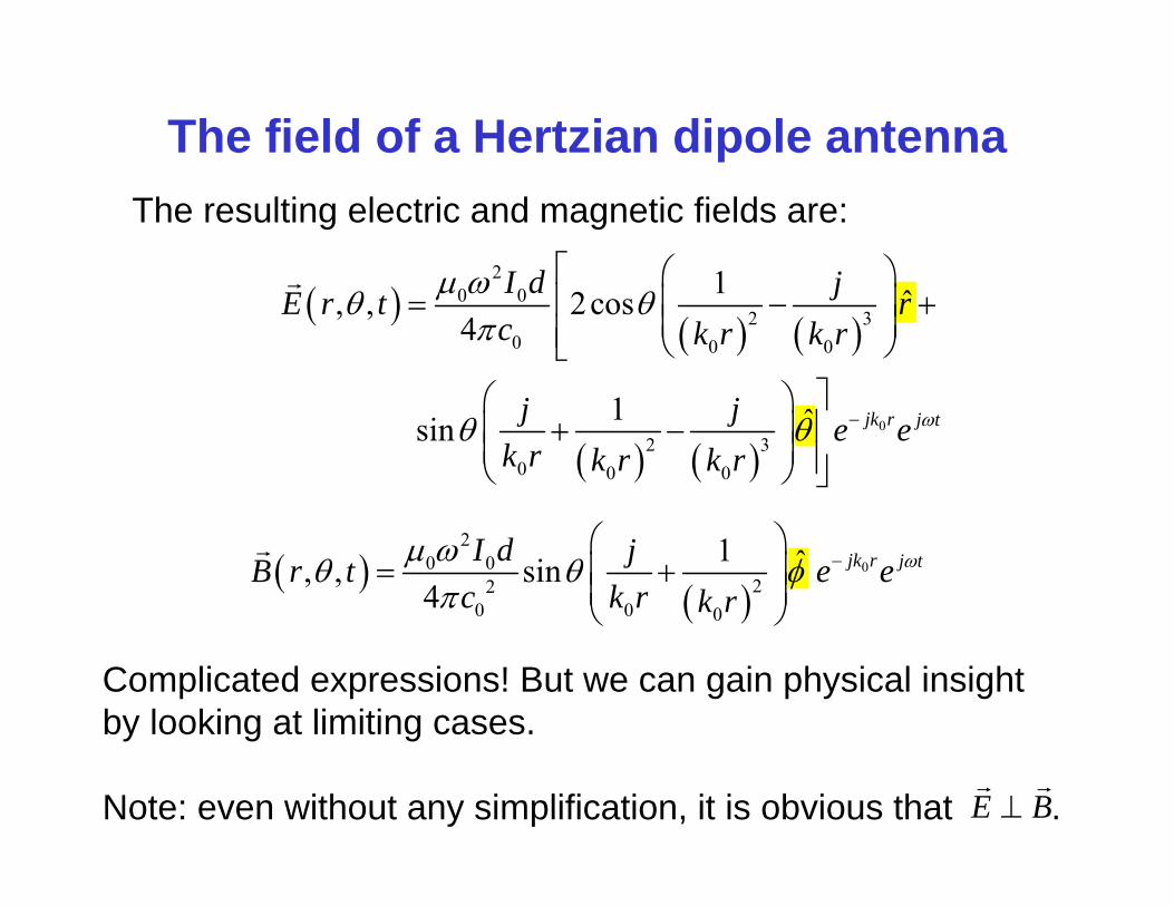
The resulting electric and magnetic fields are:
0
20 0
220 0 0
1 ˆ, , sin 4
jk r j tI d jB r t e ec k r k r
Complicated expressions! But we can gain physical insight by looking at limiting cases.
Note: even without any simplification, it is obvious that .E B
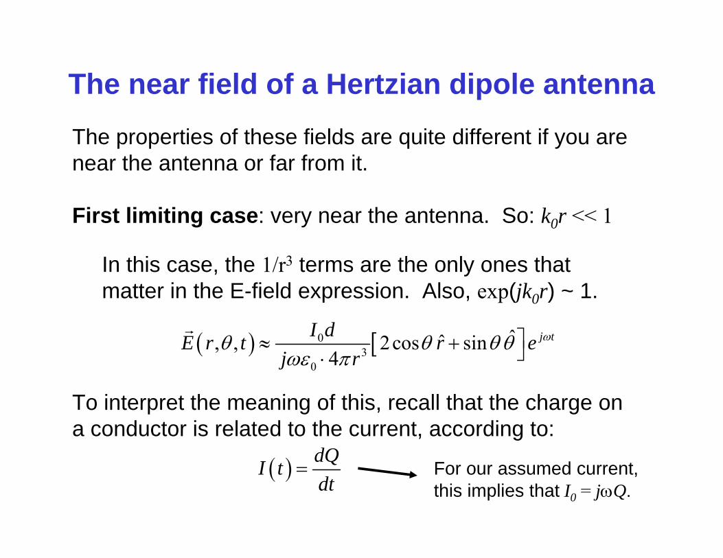
The near field of a Hertzian dipole antennaThe properties of these fields are quite different if you are near the antenna or far from it.
First limiting case: very near the antenna. So: k0r << 1
To interpret the meaning of this, recall that the charge on a conductor is related to the current, according to:
dQI tdt
For our assumed current, this implies that I0 = jQ.
03
0
ˆˆ, , 2cos sin4
j tI dE r t r ej r
In this case, the 1/r3 terms are the only ones that matter in the E-field expression. Also, exp(jk0r) ~ 1.
The near field of a Hertzian dipole antenna
30
ˆˆ, , 2cos sin4
j tQdE r et rr
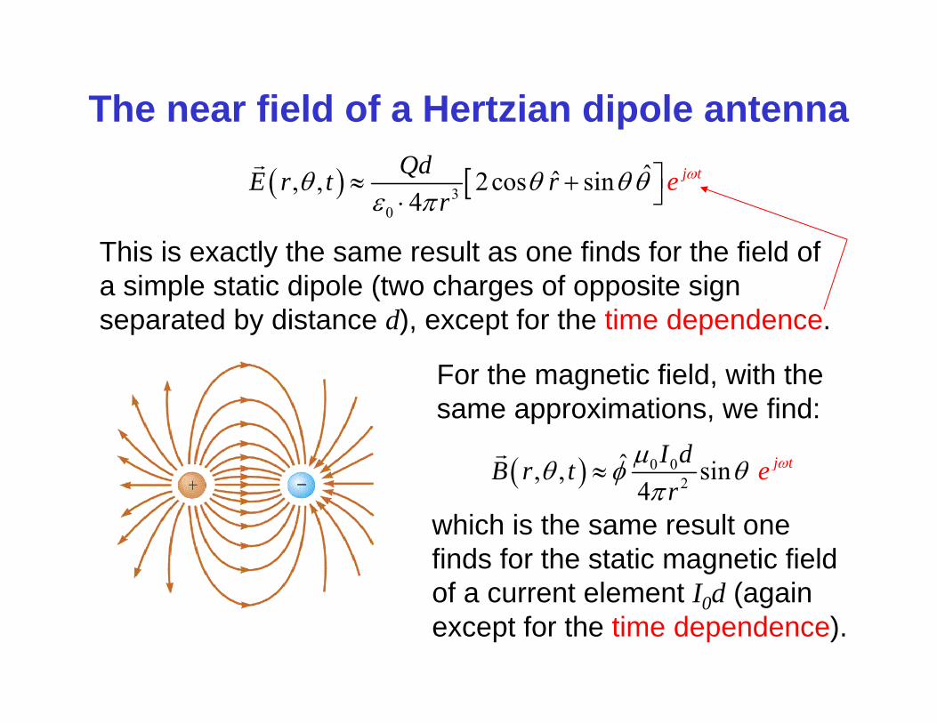
This is exactly the same result as one finds for the field of a simple static dipole (two charges of opposite sign separated by distance d), except for the time dependence.
For the magnetic field, with the same approximations, we find:
0 02
ˆ, , sin 4
j tI dB r t er
which is the same result one finds for the static magnetic field of a current element I0d (again except for the time dependence).
The near field is the quasi-static regime
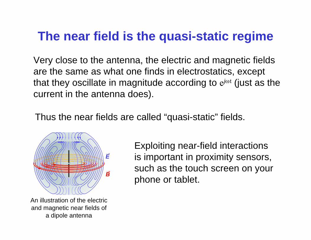
Very close to the antenna, the electric and magnetic fields are the same as what one finds in electrostatics, except that they oscillate in magnitude according to ejt (just as the current in the antenna does).
Thus the near fields are called “quasi-static” fields.
An illustration of the electric and magnetic near fields of
a dipole antenna
Exploiting near-field interactions is important in proximity sensors, such as the touch screen on your phone or tablet.
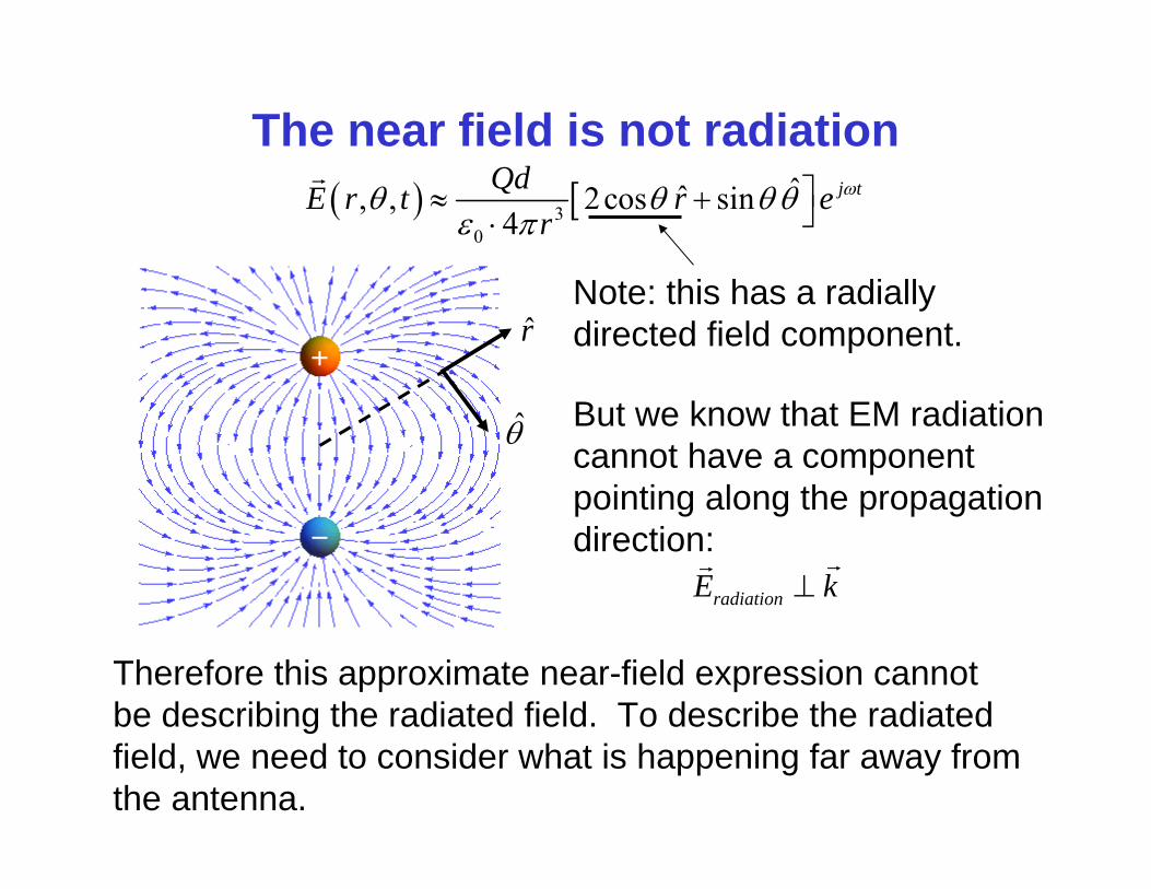
The near field is not radiation 3
0
ˆˆ, , 2cos sin4
j tQdE r t r er
r
Note: this has a radiallydirected field component.
Therefore this approximate near-field expression cannot be describing the radiated field. To describe the radiated field, we need to consider what is happening far away from the antenna.
radiationE k
But we know that EM radiation cannot have a component pointing along the propagation direction:
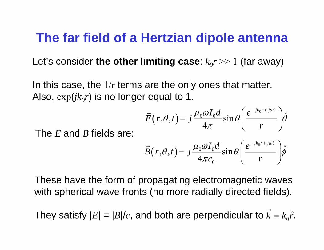
The far field of a Hertzian dipole antennaLet’s consider the other limiting case: k0r >> 1 (far away)
In this case, the 1/r terms are the only ones that matter. Also, exp(jk0r) is no longer equal to 1.
0
0 0 ˆ, , sin4
jk r j tI d eE r t jr
0
0 0
0
ˆ, , sin4
jk r j tI d eB r t jc r
The E and B fields are:
These have the form of propagating electromagnetic waves with spherical wave fronts (no more radially directed fields).
They satisfy |E| = |B|/c, and both are perpendicular to . 0 ˆk k r
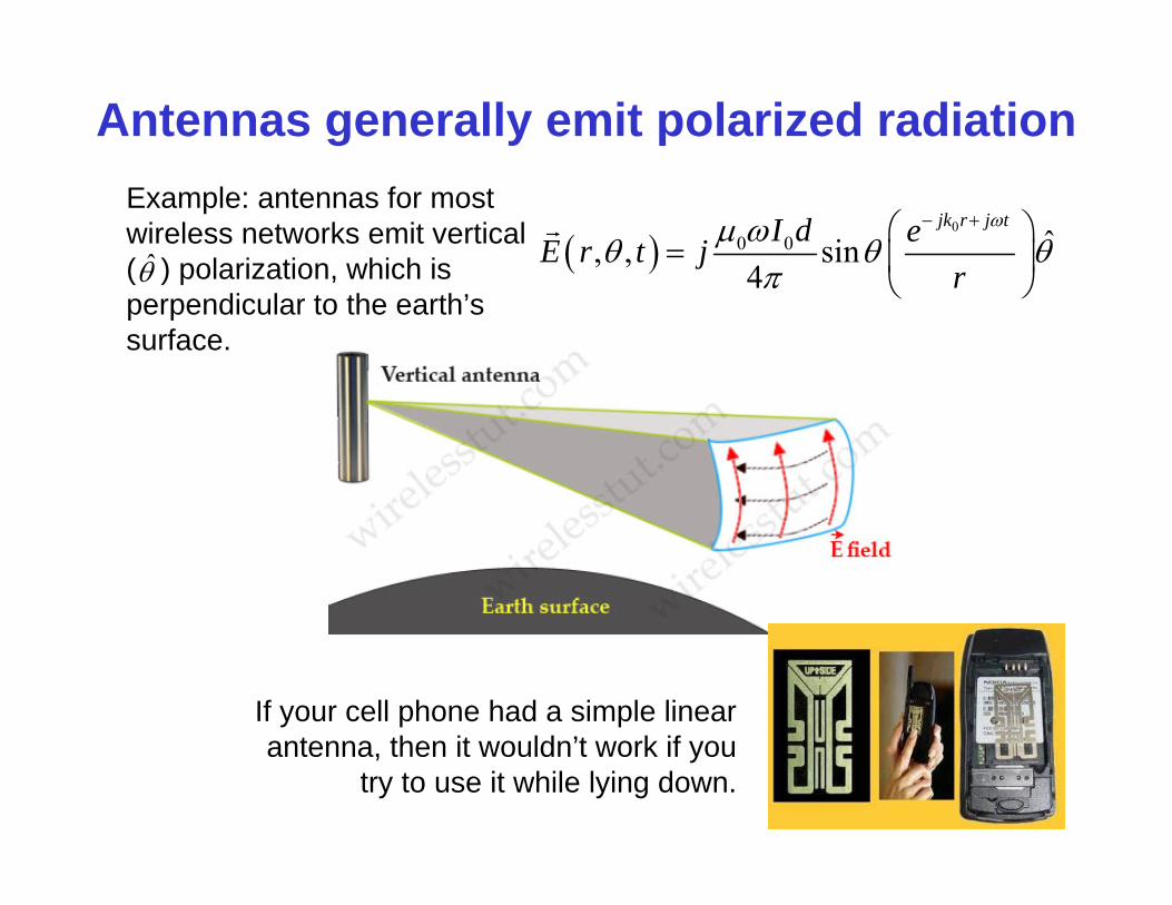
If your cell phone had a simple linear antenna, then it wouldn’t work if you
try to use it while lying down.
Antennas generally emit polarized radiation
0
0 0 ˆ, , sin4
jk r j tI d eE r t jr
Example: antennas for most wireless networks emit vertical ( ) polarization, which is perpendicular to the earth’s surface.
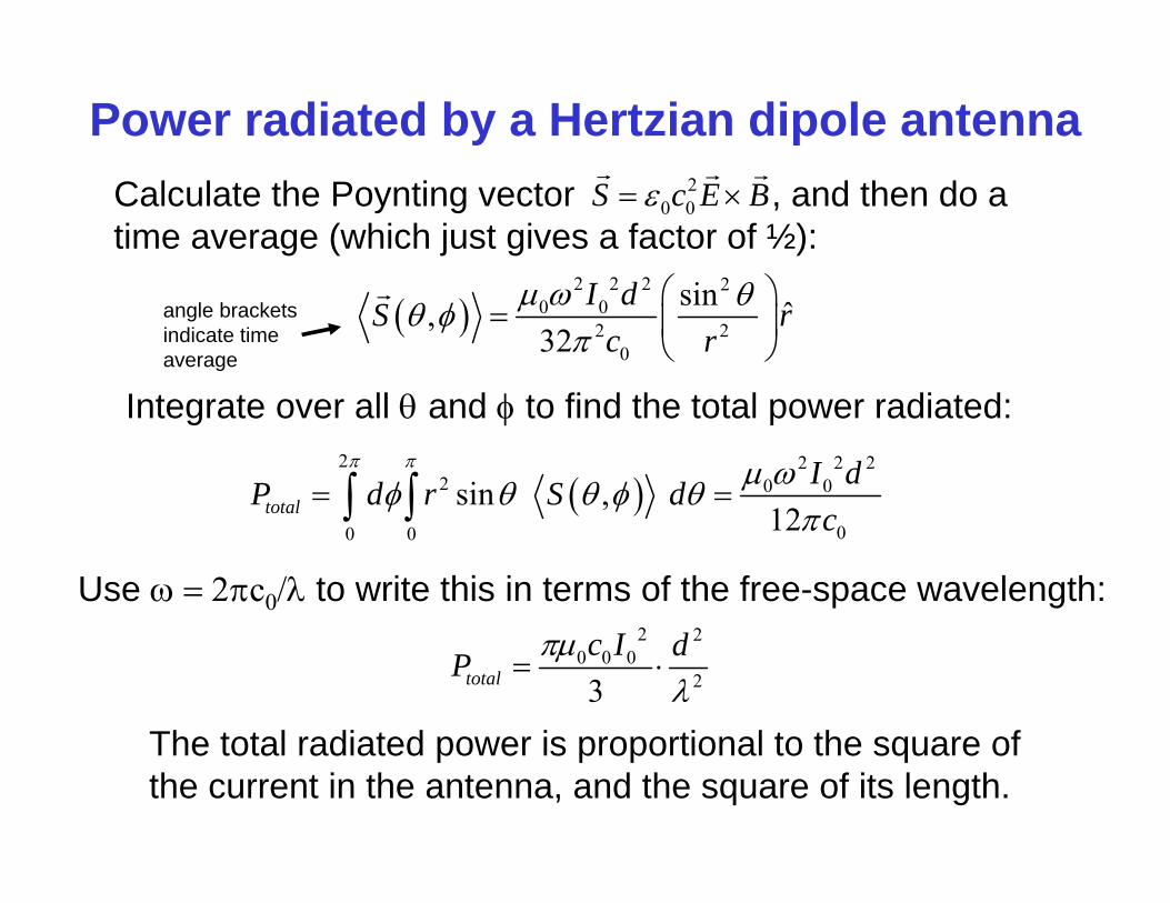
Power radiated by a Hertzian dipole antenna
2 2 2 2
0 02 2
0
sin ˆ,32
I dS rc r
Integrate over all and to find the total power radiated:
2 2 2 2
2 0 0
00 0
sin , 12total
I dP d r S dc
Use c0 to write this in terms of the free-space wavelength:2 2
0 0 023total
c I dP
The total radiated power is proportional to the square of the current in the antenna, and the square of its length.
angle brackets indicate time average
Calculate the Poynting vector , and then do a time average (which just gives a factor of ½):
20 0S c E B
Radiation resistanceSince the power radiated by the antenna varies as the square of the current, it makes sense to draw an analogy to the power dissipated in a resistor due to Ohmic heating, which is given by the well-known formula:
2P I R
Of course, for time-varying currents, we need to time-average, which contributes a factor of ½, making this:
212aveP I R
“radiation resistance” = the hypothetical resistance that would dissipate the same time-averaged power (due to Ohmic heating) as that radiated by the antenna.

For the Hertzian dipole:
Radiation resistance2 2
0 0 023total
c I dP
and therefore:2
0 02 2
0
223rad total
c dR PI
Note, since , this can also be written: 00 0
1c
2 20
02 20
2 23 3rad
d dR Z
0 0 0 377Z where is the impedance of free space.
Since a Hertzian dipole antenna has d << , its radiation resistance is much smaller than 377.
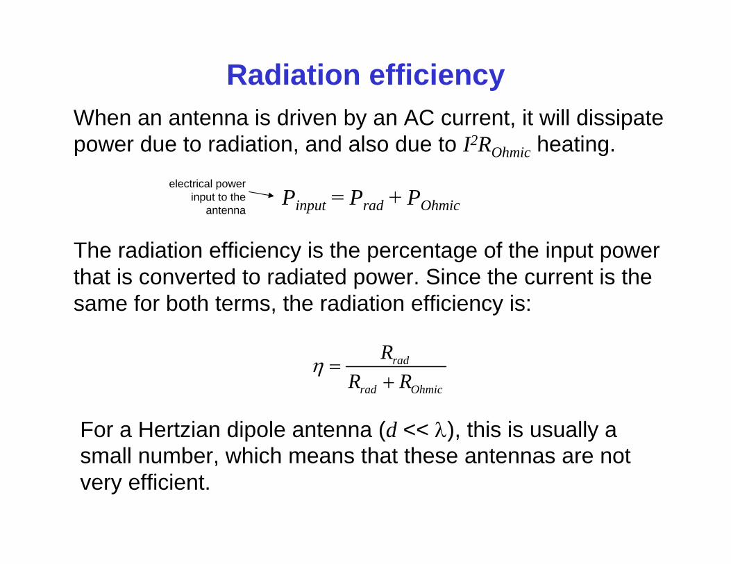
Radiation efficiencyWhen an antenna is driven by an AC current, it will dissipate power due to radiation, and also due to I2ROhmic heating.
Pinput = Prad + POhmic
The radiation efficiency is the percentage of the input power that is converted to radiated power. Since the current is the same for both terms, the radiation efficiency is:
rad
rad Ohmic
RR R
For a Hertzian dipole antenna (d << ), this is usually a small number, which means that these antennas are not very efficient.
electrical power input to the
antenna
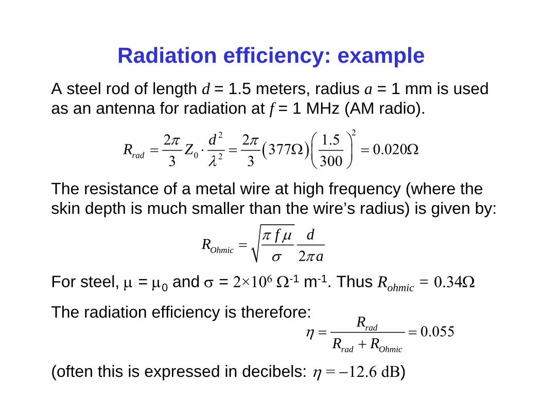
Radiation efficiency: exampleA steel rod of length d = 1.5 meters, radius a = 1 mm is used as an antenna for radiation at f = 1 MHz (AM radio).
22
0 2
2 2 1.5377 0.0203 3 300rad
dR Z
2Ohmicf dR
a
The resistance of a metal wire at high frequency (where the skin depth is much smaller than the wire’s radius) is given by:
0.055rad
rad Ohmic
RR R
The radiation efficiency is therefore:
(often this is expressed in decibels: = 12.6 dB)
For steel, = 0 and = 2×10⁶ -1 m-1. Thus Rohmic = 0.34