2246 ieee transactions on biomedical engineering, vol. …
TRANSCRIPT

2246 IEEE TRANSACTIONS ON BIOMEDICAL ENGINEERING, VOL. 54, NO. 12, DECEMBER 2007
Novel Eye Gaze Tracking TechniquesUnder Natural Head Movement
Zhiwei Zhu and Qiang Ji*, Senior Member, IEEE
Abstract—Most available remote eye gaze trackers have twocharacteristics that hinder them being widely used as the impor-tant computer input devices for human computer interaction.First, they have to be calibrated for each user individually; second,they have low tolerance for head movement and require the usersto hold their heads unnaturally still. In this paper, by exploitingthe eye anatomy, we propose two novel solutions to allow naturalhead movement and minimize the calibration procedure to onlyone time for a new individual.
The first technique is proposed to estimate the 3-D eye gazedirectly. In this technique, the cornea of the eyeball is modeledas a convex mirror. Via the properties of convex mirror, a simplemethod is proposed to estimate the 3-D optic axis of the eye. Thevisual axis, which is the true 3-D gaze direction of the user, canbe determined subsequently after knowing the angle deviationbetween the visual axis and optic axis by a simple calibration pro-cedure. Therefore, the gaze point on an object in the scene can beobtained by simply intersecting the estimated 3-D gaze directionwith the object. Different from the first technique, our secondtechnique does not need to estimate the 3-D eye gaze directly, andthe gaze point on an object is estimated from a gaze mappingfunction implicitly. In addition, a dynamic computational headcompensation model is developed to automatically update the gazemapping function whenever the head moves. Hence, the eye gazecan be estimated under natural head movement. Furthermore, itminimizes the calibration procedure to only one time for a newindividual.
The advantage of the proposed techniques over the current stateof the art eye gaze trackers is that it can estimate the eye gaze ofthe user accurately under natural head movement, without need toperform the gaze calibration every time before using it. Our pro-posed methods will improve the usability of the eye gaze trackingtechnology, and we believe that it represents an important step forthe eye tracker to be accepted as a natural computer input device.
Index Terms—Eye gaze tracking, gaze estimation, human com-puter interaction.
I. INTRODUCTION
EYE gaze is defined as the line of sight of a person. It rep-resents a person’s focus of attention. Eye gaze tracking
has been an active research topic for many decades because
Manuscript received March 19, 2005; revised December 11, 2007. Asteriskindicates corresponding author.
Z. Zhu was with the Department of Electrical, Computer and Systems En-gineering, Rensselaer Polytechnic Institute, Troy, NY 12180-3590 USA. He isnow with the Sarnoff Corporation, Princeton, NJ 08540 USA.
*Q. Ji is with Department of Electrical, Computer and Systems Engineering,Rensselaer Polytechnic Institute, SEC 6003, 110 8th Street, Troy, NY 12180-3590 USA (e-mail: [email protected]).
Color versions of one or more of the figures in this paper are available onlineat http://ieeexplore.ieee.org.
Digital Object Identifier 10.1109/TBME.2007.895750
of its potential usages in various applications such as HumanComputer Interaction (HCI), Virtual Reality, Eye Disease Diag-nosis, Human Behavior Studies, etc. For example, when a user islooking at a computer screen, the user’s gaze point at the screencan be estimated via the eye gaze tracker. Hence, the eye gazecan serve as an advanced computer input [1], which is provento be more efficient than the traditional input devices such asa mouse pointer [2]. Also, a gaze-contingent interactive graphicdisplay application can be built [3], in which the graphic displayon the screen can be controlled interactively by the eye gaze.Recently, eye gaze has also been widely used by cognitive sci-entists to study human beings’ cognition [4], memory [5], etc.
Numerous techniques [3], [6]–[17] have been proposed to es-timate the eye gaze. Earlier eye gaze trackers are fairly intru-sive in that they require physical contacts with the user, suchas placing a reflective white dot directly onto the eye [6] orattaching a number of electrodes around the eye [7]. In addi-tion, most of these technologies also require the user’s head tobe motionless during eye tracking. With the rapid technolog-ical advancements in both video cameras and microcomputers,gaze tracking technology based on the digital video analysis ofeye movements has been widely explored. Since it does not re-quire anything attached to the user, video technology opens themost promising direction for building a nonintrusive eye gazetracker. Various techniques [18]–[23], [3], [17] have been pro-posed to perform the eye gaze estimation based on eye imagescaptured by video cameras. However, most available remote eyegaze trackers have two characteristics that prevent them frombeing widely used. First, they must often be calibrated repeat-edly for each individual; second, they have low tolerance forhead movements and require the user to hold the head uncom-fortably still.
In this paper, two novel techniques are introduced to improvethe existing gaze tracking techniques. First, a simple 3-D gazetracking technique is proposed to estimate the 3-D direction ofthe gaze. Different from the existing 3-D techniques, the pro-posed 3-D gaze tracking technique can estimate the optic axisof the eye without the need to know any user-dependent param-eters about the eyeball. Hence, the 3-D direction of the gaze canbe estimated in a way allowing more easy implementation, im-proving the robustness and accuracy of the gaze estimation si-multaneously. Second, a novel 2-D mapping-based gaze estima-tion technique is introduced to allow free head movements andminimize the calibration procedure to only one time for a newindividual. A dynamic head compensation model is proposed tocompensate for the head movements so that whenever the headmoves, the gaze mapping function at a new 3-D head positioncan be updated automatically. Hence, accurate gaze information
0018-9294/$25.00 © 2007 IEEE
Authorized licensed use limited to: IEEE Transactions on SMC Associate Editors. Downloaded on October 12, 2008 at 20:15 from IEEE Xplore. Restrictions apply.
ZHU AND JI: NOVEL EYE GAZE TRACKING TECHNIQUES UNDER NATURAL HEAD MOVEMENT 2247
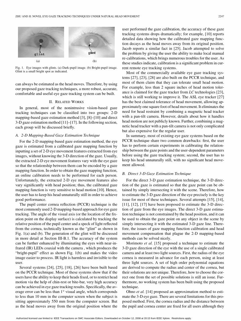
Fig. 1. Eye images with glints. (a) Dark-pupil image. (b) Bright-pupil image.Glint is a small bright spot as indicated.
can always be estimated as the head moves. Therefore, by usingour proposed gaze tracking techniques, a more robust, accurate,comfortable and useful eye gaze tracking system can be built.
II. RELATED WORKS
In general, most of the nonintrusive vision-based gazetracking techniques can be classified into two groups: 2-Dmapping-based gaze estimation method [3], [8]–[10] and direct3-D gaze estimation method [11]–[17]. In the following section,each group will be discussed briefly.
A. 2-D Mapping-Based Gaze Estimation Technique
For the 2-D mapping-based gaze estimation method, the eyegaze is estimated from a calibrated gaze mapping function byinputting a set of 2-D eye movement features extracted from eyeimages, without knowing the 3-D direction of the gaze. Usually,the extracted 2-D eye movement features vary with the eye gazeso that the relationship between them can be encoded by a gazemapping function. In order to obtain the gaze mapping function,an online calibration needs to be performed for each person.Unfortunately, the extracted 2-D eye movement features alsovary significantly with head position; thus, the calibrated gazemapping function is very sensitive to head motion [10]. Hence,the user has to keep his head unnaturally still in order to achievegood performance.
The pupil center cornea reflection (PCCR) technique is themost commonly used 2-D mapping-based approach for eye gazetracking. The angle of the visual axis (or the location of the fix-ation point on the display surface) is calculated by tracking therelative position of the pupil center and a speck of light reflectedfrom the cornea, technically known as the “glint” as shown inFig. 1(a) and (b). The generation of the glint will be discussedin more detail at Section III-B.1. The accuracy of the systemcan be further enhanced by illuminating the eyes with near-in-frared (IR) LEDs coaxial with the camera , which produces the“bright-pupil” effect as shown Fig. 1(b) and makes the videoimage easier to process. IR light is harmless and invisible to theuser.
Several systems [24], [25], [18], [26] have been built basedon the PCCR technique. Most of these systems show that if theusers have the ability to keep their heads fixed, or to restrict headmotion via the help of chin-rest or bite-bar, very high accuracycan be achieved in eye gaze tracking results. Specifically, the av-erage error can be less than 1 visual angle, which correspondsto less than 10 mm in the computer screen when the subject issitting approximately 550 mm from the computer screen. Butas the head moves away from the original position where the
user performed the gaze calibration, the accuracy of these gazetracking systems drops dramatically; for example, [10] reportsdetailed data showing how the calibrated gaze mapping func-tion decays as the head moves away from its original position.Jacob reports a similar fact in [25]. Jacob attempted to solvethe problem by giving the user the ability to make local manualre-calibrations, which brings numerous troubles for the user. Asthese studies indicate, calibration is a significant problem in cur-rent remote eye tracking systems.
Most of the commercially available eye gaze tracking sys-tems [27], [23], [28] are also built on the PCCR technique, andmost of them claim that they can tolerate small head motion.For example, less than 2 square inches of head motion toler-ance is claimed for the gaze tracker from LC technologies [23],which is still working to improve it. The ASL eye tracker [27]has the best claimed tolerance of head movement, allowing ap-proximately one square foot of head movement. It eliminates theneed for head restraint by combining a magnetic head trackerwith a pan-tilt camera. However, details about how it handleshead motion are not publicly known. Further, combining a mag-netic head tracker with a pan-tilt camera is not only complicatedbut also expensive for the regular user.
In summary, most of existing eye gaze systems based on thePCCR technique share two common drawbacks: first, the userhas to perform certain experiments in calibrating the relation-ship between the gaze points and the user-dependent parametersbefore using the gaze tracking system; second, the user has tokeep his head unnaturally still, with no significant head move-ment allowed.
B. Direct 3-D Gaze Estimation Technique
For the direct 3-D gaze estimation technique, the 3-D direc-tion of the gaze is estimated so that the gaze point can be ob-tained by simply intersecting it with the scene. Therefore, howto estimate the 3-D gaze direction of the eye precisely is the keyissue for most of these techniques. Several attempts [15], [14],[11], [12], [17] have been proposed to estimate the 3-D direc-tion of gaze from the eye images. The direct 3-D gaze estima-tion technique is not constrained by the head position, and it canbe used to obtain the gaze point on any object in the scene bysimply intersecting it with the estimated 3-D gaze line. There-fore, the issues of gaze mapping function calibration and headmovement compensation that plague the 2-D mapping-basedmethods can be solved nicely.
Morimoto et al. [15] proposed a technique to estimate the3-D gaze direction of the eye with the use of a single calibratedcamera and at least two light sources. First, the radius of the eyecornea is measured in advance for each person, using at leastthree light sources. A set of high order polynomial equationsare derived to compute the radius and center of the cornea, buttheir solutions are not unique. Therefore, how to choose the cor-rect one from the set of possible solutions is still an issue. Fur-thermore, no working system has been built using the proposedtechnique.
Ohno et al. [14] proposed an approximation method to esti-mate the 3-D eye gaze. There are several limitations for this pro-posed method. First, the cornea radius and the distance betweenthe pupil and cornea center are fixed for all users although they
Authorized licensed use limited to: IEEE Transactions on SMC Associate Editors. Downloaded on October 12, 2008 at 20:15 from IEEE Xplore. Restrictions apply.
2248 IEEE TRANSACTIONS ON BIOMEDICAL ENGINEERING, VOL. 54, NO. 12, DECEMBER 2007
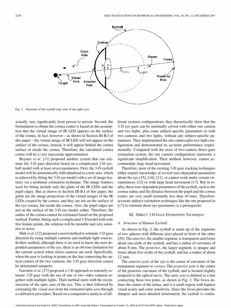
Fig. 2. Structure of the eyeball (top view of the right eye).
actually vary significantly from person to person. Second, theformulation to obtain the cornea center is based on the assump-tion that the virtual image of IR LED appears on the surfaceof the cornea. In fact, however – as shown in Section III-B.I ofthis paper – the virtual image of IR LED will not appear on thesurface of the cornea; instead, it will appear behind the corneasurface or inside the cornea. Therefore, the calculated corneacenter will be a very inaccurate approximation.
Beymer et al. [11] proposed another system that can esti-mate the 3-D gaze direction based on a complicated 3-D eye-ball model with at least seven parameters. First, the 3-D eyeballmodel will be automatically individualized to a new user, whichis achieved by fitting the 3-D eye model with a set of image fea-tures via a nonlinear estimation technique. The image featuresused for fitting include only the glints of the IR LEDs and thepupil edges. But as shown in Section III-B.I of this paper, theglints are the image projections of the virtual images of the IRLEDs created by the cornea, and they are not on the surface ofthe eye cornea, but inside the cornea. Also, the pupil edges arenot on the surface of the 3-D eye model, either. Therefore, theradius of the cornea cannot be estimated based on the proposedmethod. Further, fitting such a complicated 3-D model with onlyfew feature points, the solution will be unstable and very sensi-tive to noise.
Shih et al. [12] proposed a novel method to estimate 3-D gazedirection by using multiple cameras and multiple light sources.In their method, although there is no need to know the user-de-pendent parameters of the eye, there is an obvious limitation forthe current system when stereo cameras are used. Specifically,when the user is looking at points on the line connecting the op-tical centers of the two cameras, the 3-D gaze direction cannotbe determined uniquely.
Guestrin et al. [17] proposed a 3-D approach to remotely es-timate 3-D gaze with the use of one or two video cameras to-gether with multiple lights. Their method starts with the recon-struction of the optic axis of the eye. This is then followed byestimating the visual axis from the estimated optic axis througha calibration procedure. Based on a comparative analysis of dif-
ferent systems configurations, they theoretically show that the3-D eye gaze can be minimally solved with either one cameraand two lights, plus some subject-specific parameters or withtwo cameras and two lights, without any subject-specific pa-rameters. They implemented the one camera plus two light con-figuration and demonstrated its accurate performance experi-mentally. Compared with the most of two-camera direct gazeestimation system, the one camera configuration represents asignificant simplification. Their method, however, cannot ac-commodate large head movement.
Therefore, most of the existing 3-D gaze tracking techniqueseither require knowledge of several user-dependent parametersabout the eye [15], [14], [11], or cannot work under certain cir-cumstances [12] or with large head movement [17]. But in re-ality, these user-dependent parameters of the eyeball, such as thecornea radius and the distance between the pupil and the corneacenter, are very small (normally less than 10 mm). Therefore,accurate indirect estimation techniques like the one proposed in[17] to estimate these eye parameters is a prerequisite.
III. DIRECT 3-D GAZE ESTIMATION TECHNIQUE
A. Structure of Human Eyeball
As shown in Fig. 2, the eyeball is made up of the segmentsof two spheres with different sizes placed in front of the other[29]. The anterior, the smaller segment, is transparent and formsabout one-sixth of the eyeball, and has a radius of curvature ofabout 8 mm. The posterior, the larger segment, is opaque andforms about five-sixths of the eyeball, and has a radius of about12 mm.
The anterior pole of the eye is the center of curvature of thetransparent segment or cornea. The posterior pole is the centerof the posterior curvature of the eyeball, and is located slightlytemporal to the optical nerve. The optic axis is defined as a lineconnecting these two poles, as shown in Fig. 2. The fovea de-fines the center of the retina, and is a small region with highestvisual acuity and color sensitivity. Since the fovea provides thesharpest and most detailed information, the eyeball is contin-
Authorized licensed use limited to: IEEE Transactions on SMC Associate Editors. Downloaded on October 12, 2008 at 20:15 from IEEE Xplore. Restrictions apply.

ZHU AND JI: NOVEL EYE GAZE TRACKING TECHNIQUES UNDER NATURAL HEAD MOVEMENT 2249
uously moving so that the light from the object of primary in-terest will fall on this region. Thus, another major axis, the visualaxis, is defined as the projection of the foveal center into objectspace through the eye’s nodal point as shown in Fig. 2.Therefore, it is the visual axis that determines a person’s visualattention or direction of gaze, not the optic axis. Since the foveais a few degrees temporal to the posterior pole, the visual axiswill deviate a few degrees nasally from the optic axis. The angleformed by the intersection of the visual axis and the optic axis atthe nodal point is named as angle kappa. The angle kappa in thetwo eyes should have the same magnitude [29], approximatelyaround 5 .
Pupillary axis of the eye is defined as the 3-D line connectingthe center of the pupil and the center of the cornea .The pupillary axis is the best estimate of the location of theeye’s optic axis; if extended through the eye, it should exit verynear the anatomical posterior pole. In Fig. 2, the pupillary axisis shown as the optic axis of the eyeball. Therefore, if we canobtain the 3-D locations of the pupil center and cornea center,then the optic axis of the eye can be estimated.
B. Derivation of 3-D Cornea Center
1) Glint Formation in Cornea Reflection: When light passesthrough the eye, the boundary surface of the cornea will act likea reflective surface. Therefore, if a light source is placed in frontof the eye, the reflection from the external surface of the corneawill be captured as a very bright spot in the eye image as shownin Fig. 1(a) and (b). This special bright dot is called glint and itis the brightest and easiest reflection to detect and track.
In order to understand the formation of the glint, the externalsurface of the cornea is modelled as a convex mirror with a ra-dius . Therefore, the eye cornea serves as a convex mirrorduring the process of glint formation. Specifically, the focuspoint , the center of the curvature and the principalaxis are shown in Fig. 3. In our research, the IR LEDs are uti-lized as the light sources. Therefore, when an IR LED is placedin front of the eye, the cornea will produce a virtual image of theIR LED, which is located somewhere behind the cornea surfacealong the line that connects the cornea center and the light, asshown in the light ray diagram of the Fig. 3.
In the light ray diagram [30], the virtual image of the lightimage is the location in space where it appears that light di-verges from. Any observer from any position who is sightingalong a line at the image location will view the IR light sourceas a result of the reflected light. The reflection law of the convexmirrors [31] establishes that the virtual light position is onlydetermined by the actual position of the light and by the loca-tion of the mirror, independent of the observer position. Hence,each observer sees a virtual image at the same location regard-less of the observer’s location. Thus, the task of determining theimage location of the IR light source is to determine the locationwhere reflected light intersects. In Fig. 3, several rays of lightemanating from the IR light source are shown approaching thecornea and subsequently reflecting. Each ray is extended back-wards to a point of intersection—this point of intersection ofall extended reflected rays indicates the location of the virtualimage of IR light source.
Fig. 3. Image formation of a point light source in the cornea when the corneaserves as a convex mirror.
In our research, the cameras are the observers. Therefore, thevirtual image of the IR light source created by the cornea will beshown as a glint in the image captured by the camera. If we placetwo cameras at different locations, each camera will capture aglint corresponding to the same virtual image of the IR lightsource in space as shown in Fig. 4. Therefore, in theory, withthe use of two cameras, the 3-D location of the virtual image ofthe IR light source in space can be recovered.
2) Curvature Center of the Cornea: According to the proper-ties of the convex mirror, an incident ray that is directed towardsthe center of curvature of a mirror is reflected back along its ownpath (since it is normally incident on the mirror). Therefore, asshown in Fig. 5, if the light ray is shone directly towardsthe center of the curvature of the cornea , it will be re-flected back along its own path. Also, the virtual image of theIR light source will lie in this path. Therefore, as shown inFig. 5, the IR light source , its the virtual image and thecurvature center of the cornea will be co-linear.
Further, if we place another IR light source at a different placeas shown in Fig. 5, then the IR light source , its the vir-
tual image and the curvature center of the corneawill lie in another line . Line and line
will intersect at the point .As discussed in Section III-B.1, if two cameras are used, the
3-D locations of the virtual images and of the IR lightsources can be obtained through 3-D reconstruction. Further-more, the 3-D location of the IR light sources and can beobtained through the system calibration procedure discussed inSection V-A. Therefore, the 3-D location of the curvature centerof cornea can be obtained by intersecting the lineand as follows:
(1)
Note that when more than two IR light sources are available,a set of equations can be obtained, which can lead to a morerobust estimation of the 3-D location of cornea center.
Authorized licensed use limited to: IEEE Transactions on SMC Associate Editors. Downloaded on October 12, 2008 at 20:15 from IEEE Xplore. Restrictions apply.

2250 IEEE TRANSACTIONS ON BIOMEDICAL ENGINEERING, VOL. 54, NO. 12, DECEMBER 2007
Fig. 4. Ray diagram of the virtual image of the IR light source in front of the cameras.
Fig. 5. Ray diagram of two IR light sources in front of the cornea.
C. Computation of 3-D Gaze Direction
1) Estimation of Optic Axis: As discussed earlier, the pupil-lary axis is the best approximation of the optic axis of the eye.Therefore, after the 3-D location of the pupil center is ex-tracted, the optic axis of the eye can be estimated by con-necting the 3-D pupil center with cornea center asfollows:
(2)
However, due to the refraction index difference between theair and the aqueous humor inside the cornea, as shown in thegeometric ray diagram of the refraction at spherical surface inFig. 6, we can see that it is the virtual image of the pupil, not thepupil itself being observed from a camera. On the other hand,the pupil center is located in the optic axis of the eye because we
assume that the pupillary axis approximates the optic axis of theeye. Therefore, according to the refraction law at spherical sur-faces [30], two light rays as shown in Fig. 6 can be used to locatethe virtual image of the pupil center, which is still in the opticaxis of the eye due to the symmetry of the pupil. As a result, thevirtual image of the pupil center and the cornea center can beused to estimate the optic axis of the eye directly. Following thesame principle as for the virtual position of the light, the virtualimage of the pupil is also independent of the camera position.Hence, given two images of the same virtual pupil, its 3-D po-sition can be estimated through a 3-D triangulation.
Since the fovea is invisible from the captured eye images,the visual axis of the eye cannot be estimated directly. Withoutknowing the visual axis of the eye, the user’s fixation point inthe 3-D space still cannot be determined. However, the deviationangle kappa between the visual axis and the optic axis of the eyeis constant for each person.
Authorized licensed use limited to: IEEE Transactions on SMC Associate Editors. Downloaded on October 12, 2008 at 20:15 from IEEE Xplore. Restrictions apply.

ZHU AND JI: NOVEL EYE GAZE TRACKING TECHNIQUES UNDER NATURAL HEAD MOVEMENT 2251
Fig. 6. Ray diagram of virtual pupil image under cornea-air surface refraction.
It is assumed that there is a 3-D coordinate system attachedto the eyeball, whose axis is the principal axis of the eyeballand axis is parallel to the horizontal plane in 3-D space. Inaddition, under the pan (left-right) or tilt (up-down) movementof the head, the axis of the eye will be always parallel to thehorizontal plane. Under the swing (in-plane) movement of thehead, the eye will involuntarily perform a torsional movementaround the axis at the inverse direction of the head swing tokeep the axis parallel to the horizontal plane. However, theeye can only perform small torsional movement. Therefore, ifthe head swing angle is too large, the axis of the eye will notbe parallel to the horizontal plane.
But normally, large head swing movements are rarely hap-pened, hence, during the eye movements, it can be assumed thatthe axis of the eye will be always parallel to the horizontalplane. Therefore, if the deviation angle kappa is known, thenthe visual axis can be computed from the estimated optic axiseasily. In the following, a technique is proposed to estimate thedeviation angle kappa accurately.
2) Compensation of the Angle Deviation Between Visual Axisand Optic Axis: When a user is looking at a known point in thescreen, the 3-D location of the screen point can be known inthat the screen is calibrated. At the same time, the 3-D locationof the cornea center and the 3-D location of the virtualpupil center can be computed from the eye images via theproposed technique discussed above. Therefore, the direction of
visual axis and the direction of optic axis can be computedas follows:
(3)
In addition, let’s represent the relationship between the visualaxis and the optic axis as follows:
(4)
where is a 3 3 rotation matrix and it is constructed from thedeviation angles between the vectors and , or the deviationangle kappa. Once the rotation matrix is estimated, then the3-D visual axis can be estimated from the extracted 3-D opticaxis. Therefore, instead of estimating the deviation angle kappadirectly to obtain the relationship between the visual axis andthe optic axis, it can be encoded through the rotation matriximplicitly. In addition, the rotation matrix can be estimatedby a simple calibration as follows.
During the calibration, the user is asked to look at a set ofpre-defined point ( ) in the screen, whereduring the experiment. After the calibration is done, a set of
pairs of vectors and are obtained via (3). In addition,since the rotation matrix is an orthonormal matrix, (4) canbe represented as
(5)
Therefore, according to (4) and (5), one pair of vectors and
can give 6 linear equations so that two screen points areenough to estimate the 3 3 rotation matrix .
Once the rotation matrix is estimated, the visual axis of theeye can be estimated from the computed optic axis through(4). Finally, an accurate point of regard of the user can be com-puted by intersecting the estimated 3-D visual axis with any ob-ject in the scene.
IV. 2-D MAPPING-BASED GAZE ESTIMATION TECHNIQUE
A. Specific Eye Gaze Mapping Function
Most commercially available remote eye gaze trackers arebuilt from the PCCR technique. Specifically, the PCCR-basedtechnique consists of two major components: pupil-glint vectorextraction and gaze mapping function acquisition. Both compo-nents will be discussed briefly as follows.
1) Pupil-Glint Vector Extraction: Gaze estimation starts withpupil-glint vector extraction. After grabbing the eye image from
Authorized licensed use limited to: IEEE Transactions on SMC Associate Editors. Downloaded on October 12, 2008 at 20:15 from IEEE Xplore. Restrictions apply.

2252 IEEE TRANSACTIONS ON BIOMEDICAL ENGINEERING, VOL. 54, NO. 12, DECEMBER 2007
Fig. 7. Pupil and glint image formations when eyes are located at different positions while gazing at the same screen point (side view) and the captured eye imagesare shown on the right side.
the camera, computer vision techniques [3], [32] are proposedto extract the pupil center and the glint center robustly and ac-curately. The pupil center and the glint center are connected toform a 2-D pupil-glint vector as shown in Fig. 7.
2) Specific Gaze Mapping Function Acquisition: After ob-taining the pupil-glint vectors, a calibration procedure is pro-posed to acquire a specific gaze mapping function that will mapthe extracted pupil-glint vector to the user’s fixation point inthe screen at the current head position. The extracted pupil-glintvector is represented as and the screen gaze pointis represented by in the screen coordinate system.The specific gaze mapping function can be modelledby the following nonlinear equations [23]:
(6)
where the term in and term inamount to scale factors on and such that the gains of
on and on vary as a function of how high ( )on the screen the user is looking. Within the range of the com-puter screen, these two nonlinear terms accommodate most ofthe nonlinearity associated with the tilt of the screen (In reality,the camera is mounted below the monitor and a significant non-linearity is introduced by the screen being tilted with respect tothe camera axis). The ( ) term in also accommo-dates flattening of the corneal surface toward the edges, whichis typical in the human eye.
The coefficients , , , and , , , are estimatedfrom a set of pairs of pupil-glint vectors and the correspondingscreen gaze points. These pairs are collected in a calibrationprocedure. During the calibration, the user is required to visuallyfollow a shining dot as it displays at several predefined locations
on the computer screen. In addition, the subject must keep hishead as still as possible.
If the user does not move his head significantly after the gazecalibration, the calibrated gaze mapping function can be usedto estimate the user’s gaze point on the screen with high accu-racy, based on the extracted pupil-glint vector. But when theuser moves his head away from the position where the gazecalibration is performed, the calibrated gaze mapping functionwill fail to estimate the gaze point because of the pupil-glintvector changes caused by the head movements. In the followingsection, head movement effect on the pupil-glint vector will beillustrated.
B. Head Motion Effect on Pupil-Glint Vector
Fig. 7 shows the ray diagram of the pupil-glint vector genera-tion in the image when an eye is located at two different 3-D po-sitions and in front of the camera due to head movement.For simplicity, the eye is represented by a cornea, the cornea ismodelled as a convex mirror, and the IR light source used togenerate the glint is located at . In addition, the eye corneais further represented by a virtual sphere whose surface goesthrough the virtual pupil center , which functions exactly as areal eye cornea. All of which are applicable to subsequent fig-ures in this paper. Assume that the origin of the camera is locatedat , and are the pupil centers and and are the glintcenters generated in the image. Further, at both positions, theuser is looking at the same point of the computer screen . Ac-cording to the light ray diagram shown in Fig. 7, the generatedpupil-glint vectors and will be significantly differentin the images, as shown in Fig. 7. Two factors are responsible forthis pupil-glint vector difference: first, the eyes are at differentpositions in front of the camera; second, in order to look at the
Authorized licensed use limited to: IEEE Transactions on SMC Associate Editors. Downloaded on October 12, 2008 at 20:15 from IEEE Xplore. Restrictions apply.
ZHU AND JI: NOVEL EYE GAZE TRACKING TECHNIQUES UNDER NATURAL HEAD MOVEMENT 2253
same screen point, eyes at different positions rotate themselvesdifferently.
The eye will move as the head moves. Therefore, when theuser is gazing at a fixed point on the screen while moving hishead in front of the camera, a set of pupil-glint vectors in theimage will be generated. These pupil-glint vectors are signifi-cantly different from each other. If uncorrected, inaccurate gazepoints will be estimated after inputting them into a calibratedspecific gaze mapping function obtained at a fixed head position.
Therefore, the head movement effects on these pupil-glintvectors must be eliminated in order to utilize the specific gazemapping function to estimate the screen gaze points correctly.In the following section, a technique is proposed to eliminate thehead movement effects from these pupil-glint vectors. With thistechnique, accurate gaze screen points can be estimated undernatural head movement.
C. Dynamic Head Compensation Model
1) Approach Overview: The first step of our technique is tofind a specific gaze mapping function between the pupil-glint vector and the screen coordinate at a reference 3-Deye position . This is usually achieved via a gaze calibra-tion procedure using (6). The function can be expressed asfollows:
(7)
Assume that when the eye moves to a new position asthe head moves, a pupil-glint vector will be generated inthe image while the user is looking at the same screen point .When is far from , will be significantly different from
. Therefore, cannot be used as the input of the gaze map-ping function to estimate the screen gaze point due to thechanges of the pupil-glint vector caused by the head movement.If the changes of the pupil-glint vector caused by the headmovement can be eliminated, then a corrected pupil-glint vector
will be obtained. Ideally, this corrected pupil-glint vectoris the generated pupil-glint vector of the eye at the referenceposition when gazing at the same screen point . Therefore,this is equivalent to finding a head mapping function betweentwo different pupil-glint vectors at two different head positionswhen still gazing at the same screen point. This mapping func-tion can be written as follows:
(8)
where is the equivalent measurement of with respect to theinitial reference head position . Therefore, the screen gazepoint can be estimated accurately from the pupil-glint vectorvia the specific gaze mapping function as follows:
(9)
where the function can be called as a generalized gaze map-ping function that explicitly accounts for the head movement. Itprovides the gaze mapping function dynamically for a new eyeposition .
Via the proposed technique, whenever the head moves, a gazemapping function at each new 3-D eye position can be updated
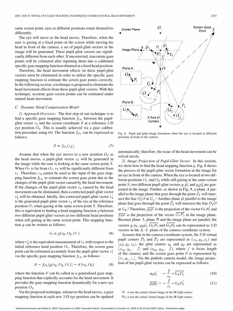
Fig. 8. Pupil and glint image formation when the eye is located at differentpositions in front of the camera.
automatically; therefore, the issue of the head movement can besolved nicely.
2) Image Projection of Pupil-Glint Vector: In this section,we show how to find the head mapping function . Fig. 8 showsthe process of the pupil-glint vector formation in the image foran eye in front of the camera. When the eye is located at two dif-ferent positions and while still gazing at the same screenpoint , two different pupil-glint vectors and are gen-erated in the image. Further, as shown in Fig. 8, a plane par-allel to the image plane that goes through the point will inter-sect the line at .1 Another plane parallel to the imageplane that goes through the point will intersect the line
at .2 Therefore, is the projection of the vector and
is the projection of the vector in the image plane.Because plane , plane and the image plane are parallel, the
vectors , , and can be represented as 2-Dvectors in the – plane of the camera coordinate system.
Assume that in the camera coordinate system, the 3-D virtualpupil centers and are represented as and
, the glint centers and are represented asand , where is focus length
of the camera, and the screen gaze point is represented by. Via the pinhole camera model, the image projec-
tion of the pupil-glint vectors can be expressed as follows:
(10)
(11)
1G is not the actual virtual image of the IR light source.2G is not the actual virtual image of the IR light source.
Authorized licensed use limited to: IEEE Transactions on SMC Associate Editors. Downloaded on October 12, 2008 at 20:15 from IEEE Xplore. Restrictions apply.

2254 IEEE TRANSACTIONS ON BIOMEDICAL ENGINEERING, VOL. 54, NO. 12, DECEMBER 2007
Fig. 9. Pupil and glint image formation when the eye is located at differentpositions in front of the camera (top-down view).
Assume that the pupil-glint vectors and are repre-sented as and respectively, and the vectors
and are represented as andrespectively. Therefore, the following equation can be derivedby combining the (10) and (11):
(12)
(13)
The above two equations describe how the pupil-glint vectorchanges as the head moves in front of the camera. Also, basedon the above equations, it is obvious that each component of thepupil-glint vector can be mapped individually. Therefore, (12)for the component of the pupil-glint vector will be derivedfirst as follows.
3) Case One: The Cornea Center and the Pupil Center Lie onthe Camera’s – Plane: Fig. 9 shows the ray diagram of thepupil-glint vector formation when the cornea center and pupilcenter of an eye happen to lie on the – plane of the cameracoordinate system. Therefore, either the generated pupil-glint
vectors and or the vectors and can berepresented as one dimensional vectors, specifically,
, , and .
According to Fig. 9, the vectors and can be rep-resented as follows:
(14)
(15)
Fig. 10. Projection into camera’s X–Z plane.
For simplicity, is used to represent the length of , is
used to represent the length of , is representedas , is represented as , is representedas and is represented as . According to the ge-
ometries shown in Fig. 9, the vectors and can befurther achieved as follows:
(16)
(17)
As shown in Fig. 9, line and line are parallel tothe axis of the camera. Therefore, and canbe obtained from the rectangles and individuallyas follows:
(18)
(19)
In the above equation, and are the glints in the image,and is the principal point of the camera. For simplicity, wechoose to represent and to represent . There-fore, after detecting the glints in the image, andcan be obtained accurately.
Further, , , and can be ob-tained from the geometries of the rectangles anddirectly. Therefore, (16) and (17) can be derived as follows:
(20)
(21)
4) Case Two: The Cornea Center and the Pupil Center do NotLie on the Camera’s – Plane: In fact, the cornea center andthe pupil center do not always lie on the camera’s – plane.However, we can obtain the ray diagram shown in Fig. 9 byprojecting the ray diagram in Fig. 8 into – plane along theaxis of the camera’s coordinate system. Therefore, as shown inFig. 10, point is the projection of the pupil center , point
Authorized licensed use limited to: IEEE Transactions on SMC Associate Editors. Downloaded on October 12, 2008 at 20:15 from IEEE Xplore. Restrictions apply.

ZHU AND JI: NOVEL EYE GAZE TRACKING TECHNIQUES UNDER NATURAL HEAD MOVEMENT 2255
is the projection of the cornea center , and point isalso the projection of the screen gaze point in the – plane.Starting from , a parallel line of line intersectswith line at . Also starting from , a parallel line
of line intersects with line at .Because represents the distance between the pupil
center to the cornea center, which will not change as the eyeballrotates, can be derived as follows:
(22)
Therefore, when the eye moves to a new location as shownin Fig. 9, can be represented as follows:
(23)
After substituting the formulations of and into (20) and(21), we can obtain as follows:
(24)
where is set as follows:
As a result, (12) and (13) can be finally obtained as follows:
(25)
(26)
The above equations constitute the head mapping functionbetween the pupil-glint vectors of the eyes at different positionsin front of the camera, while gazing at the same screen point.
5) Iterative Algorithm for Gaze Estimation: Equations (25)and (26) require the knowledge of gaze pointon the screen. However, the gaze point is the one that needsto be estimated. As a result, the gaze point is also a variableof the head mapping function , which can be further expressedas follows:
(27)
Assume that a specific gaze mapping function is knownvia the calibration procedure described in Section IV-A.2.Therefore, after integrating the head mapping function intothe specific gaze mapping function via (9), the general-ized gaze mapping function can be recursively rewritten asfollows:
(28)
Given the extracted pupil-glint vector from the eye imageand the new location that the eye has moved to, (28) becomesa recursive function. An iterative solution is proposed to solve it.
Fig. 11. Configuration of the gaze tracking system.
First, the screen center is chosen as an initial gaze point,then a corrected pupil-glint vector can be obtained from thedetected pupil-glint vector via the head mapping function .By inputting the corrected pupil-glint vector into the specificgaze mapping function , a new screen gaze point can beestimated. is further used to compute a new corrected pupil-glint vector . The loop continues until the estimated screengaze point does not change any more. Usually, the wholeiteration process will converge in less than 5 iterations, whichmakes the real-time implementation possible.
V. EXPERIMENT RESULTS
A. System Setup
Our system consists of two cameras mounted under the com-puter monitor, as shown in Fig. 11. An IR illuminator is mountedaround the center of the camera lens to produce the corneal glintin the eye image.
Before the usage of the system, two steps are performed tocalibrate the system. The first step is to obtain the parametersof the stereo camera system, which is obtained through cameracalibration [33]. Once the stereo camera system is calibrated,given any point in front of it, the 3-D positionof can be reconstructed from the image points of in bothcameras. The second step is to obtain the 3-D positions of theIR LEDs and the computer screen in the stereo camera system.Since the IR LEDs and the computer screen are located behindthe view-field of the stereo camera system, they cannot be ob-served directly by the stereo camera system. Therefore, similarto [11], [12], a planar mirror with a set of fiducial markers at-tached to the mirror surface is utilized. With the help of theplanar mirror, the virtual images of the IR LEDs and the com-puter screen reflected by the mirror can be observed by the stereocamera system. Thus, the 3-D locations of the IR LEDs and thecomputer screen can be calibrated after obtaining the 3-D loca-tions of their virtual images. In the following sections, experi-ment results of both gaze tracking techniques will be reported.
B. Performance of 3-D Gaze Tracking Technique
1) Gaze Estimation Accuracy: Once the system is calibratedand the angle deviation between the visual axis and the optic
Authorized licensed use limited to: IEEE Transactions on SMC Associate Editors. Downloaded on October 12, 2008 at 20:15 from IEEE Xplore. Restrictions apply.

2256 IEEE TRANSACTIONS ON BIOMEDICAL ENGINEERING, VOL. 54, NO. 12, DECEMBER 2007
TABLE IGAZE ESTIMATION ACCURACY FOR THE FIRST SUBJECT
axis for a new user is obtained, his gaze point on the screen canbe determined by intersecting the estimated 3-D visual axis ofthe eye with the computer screen. In order to test the accuracyof the gaze tracking system, seven users were involved in theexperiments and none of them wears glasses.
Personal calibration is needed for each user before using ourgaze tracking system in order to obtain the angle deviation ofthe visual axis and the optic axis. The calibration procedure de-scribed in Section III-C.2 is very fast and only lasts for less than5 s. Once the calibration is done, the user does not need to dothe calibration any more if he wants to use the system later.
During the experiments, a marker will display at nine fixedlocations in the screen randomly, and the user is asked to gazeat the marker when it appears at each location. The experimentcontains five 1-minute sessions. At each session, the user is re-quired to position his head at a different position purposely.Table I summarizes the computed gaze estimation accuracy forthe first subject, where the last column represents the averagedistance from the user to the camera during each session. Asshown in Table I, the accuracy of the gaze tracker (mean andstandard deviation ) significantly depends on the user’s dis-tance to the camera. Normally, as the user moves closer to thecamera, the gaze accuracy will increase dramatically. This is be-cause the resolution of the eye image increases as the user movescloser to the camera. Also, the vertical accuracy is lower thanthe horizontal accuracy due to lower vertical image resolution(480 pixels) as compared to horizontal resolution (640 pixels).Besides image resolution, the short focus length with our cur-rent camera further limits the range of the subject to the camera.The gaze accuracy can be improved with a zoomable lens and ahigh resolution camera.
Table II summarizes the computed average gaze estimationaccuracy for all the seven subjects during the experiments.During the experiments, the allowed head movement volumeis around 200 mm in the , , and directions respectivelycentered at approximately 350 mm to the camera. On the otherhand, the head movement volume is mostly limited by thedistance from the user to the camera. When the user movescloser to the camera, the allowed head movement volume alongthe and directions will get smaller, but with a highergaze accuracy. When the user moves away from the camera,the allowed head movement volume along the and direc-tions will become larger, but the gaze accuracy will decreasesignificantly. Therefore, when the user has the largest allowedhead movement, which is around 200 mm along the anddirections, it will also produce the largest gaze estimation error,which is around 2 normally.
TABLE IIAVERAGE GAZE ESTIMATION ACCURACY FOR SEVEN SUBJECTS
In summary, within the allowed head movement volume, theaverage horizontal angular gaze accuracy is 1.47 and the av-erage vertical angular gaze accuracy is 1.87 for all these sevenusers, which is acceptable for many Human Computer Interac-tion (HCI) applications, allowing natural head movement.
2) Comparison With Other Systems: Table III shows thecomparison of accuracy and allowable head movements amongseveral practically working gaze tracking systems that allownatural head movements. In addition, all of these systems werebuilt recently and require only a very simple personal calibra-tion instead of a tedious gaze mapping function calibration. Forsimplicity, only the depth or direction of the allowed headmovement is illustrated, as shown in the second column ofTable III. We can see that our proposed technique can providea competitive gaze accuracy as well as a large head movementvolume with only one stereo camera system and without thehelp of a face tracking system. Therefore, it represents thestate of the art in the gaze tracking research under natural headmovements.
C. Performance of 2-D Mapping Based Gaze TrackingTechnique
1) Head Compensation Model Validation: For the proposed2-D mapping-based gaze tracking technique, (25) and (26) ofthe head mapping function are validated first by the followingexperiments.
A screen point is chosenas the gaze point. The user gazes at this point from twenty dif-ferent locations in front of the camera; at each location, thepupil-glint vector and the 3-D pupil center are collected. The3-D pupil centers and the pupil-glint vectors of the first twosamples , are shown in Table IV, where serves as the
Authorized licensed use limited to: IEEE Transactions on SMC Associate Editors. Downloaded on October 12, 2008 at 20:15 from IEEE Xplore. Restrictions apply.

ZHU AND JI: NOVEL EYE GAZE TRACKING TECHNIQUES UNDER NATURAL HEAD MOVEMENT 2257
TABLE IIICOMPARISON WITH OTHER SYSTEMS
TABLE IVPUPIL-GLINT VECTOR COMPARISON AT DIFFERENT EYE LOCATIONS
Fig. 12. Pupil-glint vector transformation errors. (a) Transformation error on theX component of the pupil-glint vector. (b) Transformation error on the Y com-ponent of the pupil-glint vector.
reference position. The second column indicates the originalpupil-glint vectors, while the third column indicates the trans-formed pupil-glint vectors by the head compensation model.The difference between the transformed pupil-glint vector ofand the reference pupil-glint vector at is defined as the trans-formation error.
Fig. 12 illustrates the transformation errors for all thesetwenty samples. It is observed that the average transformationerror is only around 1 pixel, which validates our proposed headcompensation model.
2) Gaze Estimation Accuracy: In order to test the accuracy ofthe gaze tracking system, seven users were asked to participatein the experiment.
For the first user, the gaze mapping function calibration wasperformed when the user was sitting approximately 330 mmfrom the camera. After the calibration, the user was asked tostand up for a while. Then, the user was asked to sit approxi-mately 360 mm from the camera and follow a shining object thatwould display at 12 different pre-specified positions across thescreen. The user was asked to reposition his head to a different
position before the shining object moved to the next position.Fig. 13 displays the error between the estimated gaze points andthe actual gaze points. The average horizontal error is around4.41 mm in the screen, which corresponds to around 0.51 an-gular accuracy. The average vertical error is around 6.62 mmin the screen, which corresponds to around 0.77 angular ac-curacy. Also, it shows that our proposed technique can handlehead movements very well.
When the user moves his head away from the camera, the eyein the image will become smaller. Due to the increased pixelmeasurement error caused by the lower image resolution, thegaze accuracy of the eye gaze tracker will decrease as the usermoves away from the camera.
In another experiment, the effect of the distance to the cameraon the gaze accuracy of our system is analyzed. The second userwas asked to perform the gaze calibration when he was sittingaround 360 mm to the camera. After the calibration, the userwas positioned at five different locations, which have differentdistances to the camera as listed in Table V. At each location, theuser was asked to follow the moving objects that will display 12
Authorized licensed use limited to: IEEE Transactions on SMC Associate Editors. Downloaded on October 12, 2008 at 20:15 from IEEE Xplore. Restrictions apply.
2258 IEEE TRANSACTIONS ON BIOMEDICAL ENGINEERING, VOL. 54, NO. 12, DECEMBER 2007
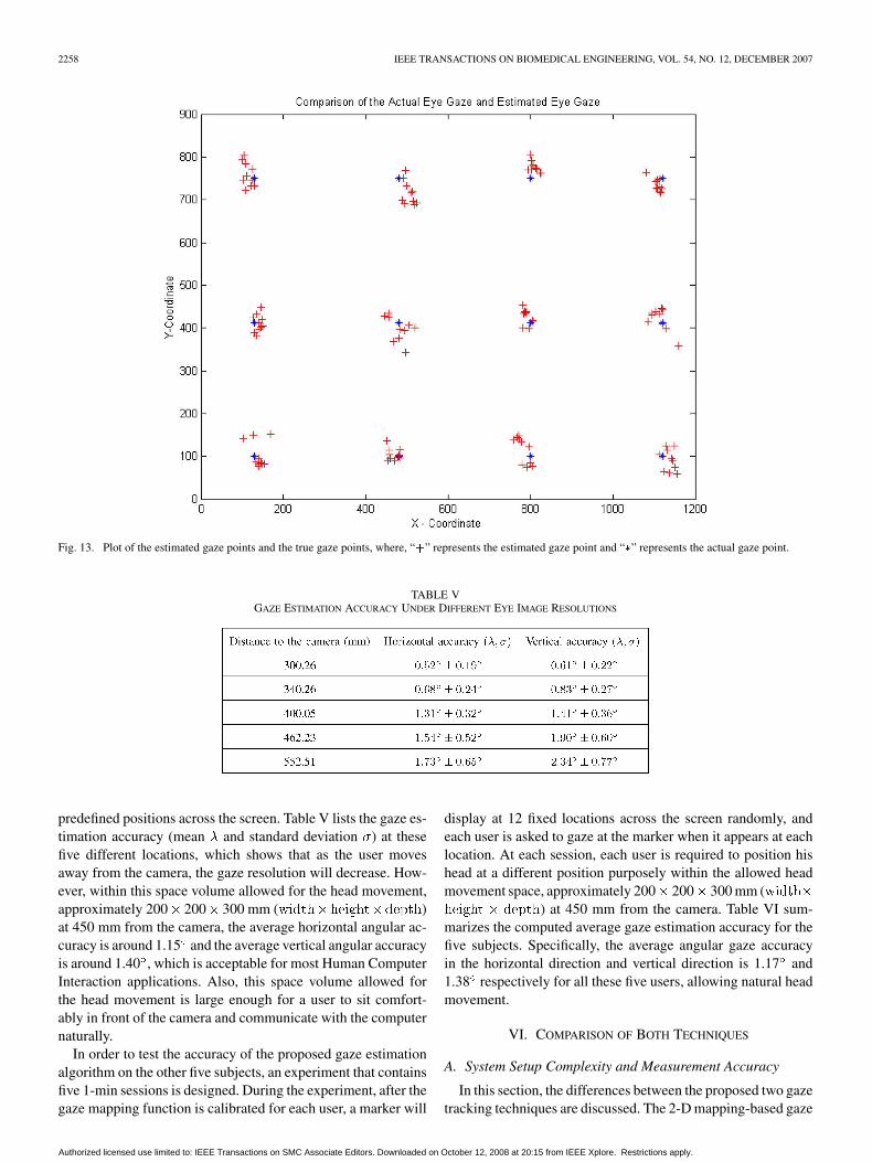
Fig. 13. Plot of the estimated gaze points and the true gaze points, where, “+” represents the estimated gaze point and “�” represents the actual gaze point.
TABLE VGAZE ESTIMATION ACCURACY UNDER DIFFERENT EYE IMAGE RESOLUTIONS
predefined positions across the screen. Table V lists the gaze es-timation accuracy (mean and standard deviation ) at thesefive different locations, which shows that as the user movesaway from the camera, the gaze resolution will decrease. How-ever, within this space volume allowed for the head movement,approximately 200 200 300 mm ( )at 450 mm from the camera, the average horizontal angular ac-curacy is around 1.15 and the average vertical angular accuracyis around 1.40 , which is acceptable for most Human ComputerInteraction applications. Also, this space volume allowed forthe head movement is large enough for a user to sit comfort-ably in front of the camera and communicate with the computernaturally.
In order to test the accuracy of the proposed gaze estimationalgorithm on the other five subjects, an experiment that containsfive 1-min sessions is designed. During the experiment, after thegaze mapping function is calibrated for each user, a marker will
display at 12 fixed locations across the screen randomly, andeach user is asked to gaze at the marker when it appears at eachlocation. At each session, each user is required to position hishead at a different position purposely within the allowed headmovement space, approximately 200 200 300 mm (
) at 450 mm from the camera. Table VI sum-marizes the computed average gaze estimation accuracy for thefive subjects. Specifically, the average angular gaze accuracyin the horizontal direction and vertical direction is 1.17 and1.38 respectively for all these five users, allowing natural headmovement.
VI. COMPARISON OF BOTH TECHNIQUES
A. System Setup Complexity and Measurement Accuracy
In this section, the differences between the proposed two gazetracking techniques are discussed. The 2-D mapping-based gaze
Authorized licensed use limited to: IEEE Transactions on SMC Associate Editors. Downloaded on October 12, 2008 at 20:15 from IEEE Xplore. Restrictions apply.

ZHU AND JI: NOVEL EYE GAZE TRACKING TECHNIQUES UNDER NATURAL HEAD MOVEMENT 2259
TABLE VIAVERAGE GAZE ESTIMATION ACCURACY FOR FIVE SUBJECTS
estimation method does not require knowledge of the 3-D direc-tion of the eye gaze to determine the gaze point on an object; in-stead, it estimates the gaze point on the object from a gaze-map-ping function directly by inputting a set of features extractedfrom the eye image. The gaze-mapping function is usually ob-tained through a calibration procedure repeated for each person.
The calibrated gaze mapping function is very sensitive tohead motion; consequently, a complicated head-motion com-pensation model is proposed to eliminate the effect of head mo-tion on the gaze-mapping function. Thus, the 2-D mapping-based method can work under natural head movement. Sincethe 2-D mapping-based method is proposed to estimate the gazepoints on a specific object, a new gaze-mapping function cali-bration must be performed each time when a different object ispresented.
In contrast, the 3-D gaze estimation technique estimates the3-D direction of the eyeball’s visual axis directly, and deter-mines the gaze by intersecting the visual axis with the objectin the scene. Thus, it can be used to estimate the gaze point onany object in the scene without the use of tedious gaze-mappingfunction calibration. Furthermore, since this method is not con-strained by head position, the complicated head-motion com-pensation model can be avoided. But the 3-D technique needs anaccurate stereo camera system, and the accuracy of the 3-D gazeestimation technique is affected by the accuracy of the stereocamera system significantly.
In terms of accuracy, the experiments indicate that the 2-Dmapping-based gaze estimation technique is more accurate thanthe 3-D gaze tracking technique. For example, for a user who issitting approximately 340 mm from the camera, the 2-D map-ping-based gaze estimation technique can achieve 0.68 accu-racy in the horizontal direction and 0.83 accuracy in the ver-tical direction; on the other hand, the direct 3-D gaze estima-tion technique only achieves 1.14 accuracy in the horizontaldirection and 1.58 accuracy in the vertical direction. The mainsource of errors for the 3-D method results from the calibrationerrors, both with the estimated camera parameters and with theestimated IR light position. Therefore, we can improve the cal-ibration accuracy to improve the 3-D gaze estimation accuracy.
Both gaze tracking techniques proposed in the paper are im-plemented using C++ on a PC with a Xeon (TM) 2.80 GHz CPUand a 1.00 GB RAM. The image resolution of the cameras is640 480 pixels, and the built gaze tracking systems can run atapproximately 25 fps comfortably.
VII. CONCLUSION
In this paper, based on exploiting eye’s anatomy, two noveltechniques are proposed to improve the existing gaze trackingtechniques. First, a simple direct method is proposed to estimatethe 3-D optic axis of a user without using any user-dependenteyeball parameters. The method is more feasible to work on dif-ferent individuals without tedious calibration. Second, a novel2-D mapping-based gaze estimation technique is proposed toallow free head movement and minimize the number of personalcalibration procedures. Therefore, the eye gaze can be estimatedwith high accuracy under natural head movement, with the per-sonal calibration being minimized simultaneously. By the noveltechniques proposed in this paper, two common drawbacks ofthe existing eye gaze trackers can be eliminated or minimizednicely so that the eye gaze of a user can be estimated under nat-ural head movement, with minimum personal calibration.
REFERENCES
[1] R. J. K. Jacob, “The use of eye movements in human computer inter-action techniques: What you look at is what you get,” ACM Trans. Inf.Syst., vol. 9, no. 3, pp. 152–169, 1991.
[2] S. Zhai, C. H. Morimoto, and S. Ihde, “Manual and gaze inputcascaded (magic) pointing,” in Proc. ACM SIGHCI-Human FactorsComput. Syst. Conf., 1999, pp. 246–253.
[3] Z. Zhu and Q. Ji, “Eye and gaze tracking for interactive graphic dis-play,” Mach. Vis. Applicat., vol. 15, no. 3, pp. 139–148, 2004.
[4] S. P. Liversedge and J. M. Findlay, “Saccadic eye movements and cog-nition,” Trends in Cognitive Science, vol. 4, no. 1, pp. 6–14, 2000.
[5] M. F. Mason, B. M. Hood, and C. N. Macrae, “Look into my eyes: Gazedirection and person memory,” Memory, vol. 12, pp. 637–643, 2004.
[6] S. Milekic, “The more you look the more you get: Intention-based in-terface using gaze-tracking,” in Trant, J.(Des.) Museums and the Web2002: Selected Papers from an Int. Conf., Archives and Museum Infor-matics, 2002, pp. 1–27.
[7] K. Hyoki, M. Shigeta, N. Tsuno, Y. Kawamuro, and T. Kinoshita,“Quantitative electro-oculography and electroencephalography as in-dexes of alertness,” Electroencephalogr. Clinical Neurophysiol., vol.106, pp. 213–219, 1998.
[8] K. H. Tan, D. Kriegman, and H. Ahuja, “Appearance based eye gazeestimation,” in Proce. IEEE Workshop Applications of Computer Vi-sion, 2002, pp. 191–195.
[9] J. Zhu and J. Yang, “Subpixel eye gaze tracking,” in Proc. IEEE Inr.Conf. Automatic Face and Gesture Recognition, Washington, D.C.,2002, pp. 131–136.
[10] C. H. Morimoto and M. Mimica, “Eye gaze tracking techniques forinteractive applications,” Comput. Vi. Image Understand., Special Issueon Eye Detection and Tracking, vol. 98, no. 1, pp. 4–24, 2005.
[11] D. Beymer and M. Flickner, “Eye gaze tracking using an active stereohead,” in Proc. Int. Conf. Computer Vision and Pattern Recognition,2003, pp. 451–458.
[12] S. W. Shih and J. Liu, “A novel approach to 3-D gaze tracking usingstereo cameras,” IEEE Trans. Syst. Man Cybern. B, vol. 34, no. 1, pp.234–245, Feb. 2004.
[13] J. Wang, E. Sung, and R. Venkateswarlu, “Eye gaze estimation from asingle image of one eye,” in Proc. Int. Conf. Computer Vision, 2003,pp. 136–143.
[14] T. Ohno, N. Mukawa, and A. Yoshikawa, “Freegaze: A gaze trackingsystem for everyday gaze interaction,” in Proc. Symp. ETRA 2002,2002, pp. 125–132.
[15] C. H. Morimoto, A. Amir, and M. Flickner, “Detecting eye positionand gaze from a single camera and 2 light sources,” in Proc. Int. Conf.Pattern Recognition, 2002, pp. 314–317.
[16] Y. Matsumoto, T. Ogasawara, and A. Zelinsky, “Behavior recognitionbased on head pose and gaze direction measurement,” in Proc. 2000IEEE/RSJ Int. Conf. Intell. Robots Syst., 2000, pp. 2127–2132.
[17] E. D. Guestrin and M. Eizenman, “General theory of remote gaze es-timation using the pupil center and corneal reflections,” IEEE Trans.Biomed. Eng., vol. 53, no. 6, pp. 1124–1133, Jun. 2006.
Authorized licensed use limited to: IEEE Transactions on SMC Associate Editors. Downloaded on October 12, 2008 at 20:15 from IEEE Xplore. Restrictions apply.

2260 IEEE TRANSACTIONS ON BIOMEDICAL ENGINEERING, VOL. 54, NO. 12, DECEMBER 2007
[18] Y. Ebisawa, M. Ohtani, and A. Sugioka, “Proposal of a zoom and focuscontrol method using an ultrasonic distance-meter for video-based eye-gaze detection under free-hand condition,” in Proc. 18th Annu. Int.Conf. IEEE Eng. Med. Biol. Soc., 1996, pp. 523–525.
[19] C. H. Morimoto, D. Koons, A. Amir, and M. Flickner, “Frame-ratepupil detector and gaze tracker,” in IEEE ICCV’99 Frame-Rate Work-shop, 1999, pp. 1–6.
[20] A. T. Duchowski, Eye Tracking Methodology: Theory and Practice.New York: Springer Verlag, 2002.
[21] R. J. K. Jacob and K. S. Karn, “Eye tracking in human-computer inter-action and usability research: Ready to deliver the promises,” in TheMind’s Eyes: Cognitive and Applied Aspects of Eye Movements, J.Hyona, R. Radach, and H. deubel, Eds. Oxford, U.K.: Elsevier Sci-ence, 2003.
[22] D. H. Yoo and M. J. Chung, “A novel nonintrusive eye gaze estimationusing cross-ratio under large head motion,” Comput. Vis. Image Under-stand., Special Issue on Eye Detection and Tracking, vol. 98, no. 1, pp.25–51, 2005.
[23] LC Technologies, Inc., McLean, VA [Online]. Available: http://www.eyegaze.com
[24] T. E. Hutchinson, K. P. White Jr., K. C. Reichert, and L. A. Frey,“Human-computer interaction using eye-gaze input,” IEEE Trans.Syst., Man, Cybern., vol. 19, no. 6, pp. 1527–1533, Nov. 1989.
[25] R. J. K. Jacob, Eye-Movement-Based Human-Computer InteractionTechniques: Towards Non-Command Interfaces. Norwood, NJ:Ablex, 1993, vol. 4, pp. 151–190.
[26] C. H. Morimoto, D. Koons, A. Amir, and M. Flickner, “Pupil detectionand tracking using multiple light sources,” Image Vis. Comput., vol. 18,pp. 331–336, 2000.
[27] Applied Science Laboratories [Online]. Available:http://www.a-s-l.com
[28] SensoMotoric [Online]. Available: http://www.smi.de[29] C. W. Oyster, The Human Eye: Structure and Function. Sunderland,
MA: Sinauer Associates, Inc., 1999.[30] M. Katz, Introduction to Geometrical Optics. Singapore: World Sci-
entific, 2002.[31] The Reflection and the Ray Model of Light [Online]. Available: http://
www.glenbrook.k12.il.us/gbssci/phys/Class/refln/u13l4a.html[32] Z. Zhu and Q. Ji, “Robust real-time eye detection and tracking under
variable lighting conditions and various face orientations,” Comput.Vis. Image Understand., Special Issue on Eye Detection and Tracking,vol. 38, no. 1, pp. 124–154, 2005.
[33] Z. Zhang, “A flexible new technique for camera calibration,” IEEETrans. Pattern Anal. Mach. Intell., vol. 22, no. 11, pp. 1330–1334, Nov.2000.
Zhiwei Zhu received the B.S. degree in computerscience from the University of Science and Tech-nology, Beijing, China, in 2000, the M.S. degreein computer science from University of Nevada,Reno, in 2002, and the Ph.D. degree in electrical andcomputer engineering from Rensselaer PolytechnicInstitute, Troy, NY, in December 2005.
He is currently a Member of Technical Staff in theComputer Vision Laboratory, Sarnoff Corporationin Princeton, NJ. His interests are in computervision, pattern recognition, image processing and
human-computer interaction.
Qiang Ji (SM’03) received the Ph.D. degree in elec-trical engineering from University of Washington,Seattle, in 1998.
He is currently a tenured Associate Professor atthe Department of Electrical, Computer, and Sys-tems Engineering, Rensselaer Polytechnic Institute(RPI), Troy, NY. Previously, he held teaching andresearch positions at University of Nevada, CarnegieMellon University, and Air Force Research Labora-tory. His research interests are in computer vision,probabilistic reasoning with graphical models, and
decision making under uncertainty. Dr. Ji has published over 100 articles inpeer-reviewed conferences and journals in these areas.
Dr. Ji has organized and served as PC members for many international con-ferences and workshops. He is on the editorial boards of image and vision com-puting journal, and is an associate editor for Pattern Recognition Letters journaland for IEEE TRANSACTIONS ON SYSTEMS, MAN, AND CYBERNETICS—PART A:SYSTEMS AND HUMANS. He was a lead Guest Editor for a Special Issue on eyedetection and tracking for the Journal of Computer Vision and Image Under-standing, 2005. He has received several awards including the Research Excel-lence Award from RPI’s School of Engineering, 2006; the Best Paper Awardfrom the IEEE TRANSACTIONS ON VEHICULAR TECHNOLOGY, 2004; the BestPaper Award from IEEE Computer Vision and Pattern Recognition Workshopon Face Recognition Grand Challenge Experiments, 2005; and the Honda Initi-ation Award, 1998.
Authorized licensed use limited to: IEEE Transactions on SMC Associate Editors. Downloaded on October 12, 2008 at 20:15 from IEEE Xplore. Restrictions apply.