220000 plumbing, general purpose - slone assoclogin.sloneassoc.com/login/documents/addendum...
TRANSCRIPT

TLC ENG I N EE RI N G FO R AR C H I TE C T U RE , IN C .
1650 Pruden t ia l D r i ve . Su i te 200 . Jacksonv i l l e , FL 32207 -8149 Phone 904 .306 .9111 www. t l c -eng ineers .com Fax 904 .306.9117
October 22, 2010
NAVFAC Southeast PWD Mayport FEAD Building 1966 Bon Homme Richard P. O. Box 280073 Mayport FL 32228-0073 Re: Repair FRC Bldg 1553 Mayport Brian Price CIV: Please see the attached Addendum #1. The addendum addresses specifications not originally included in the 100% submission and modifications to previously submitted specification sections and the submittal register. The addendum includes:
220000 PLUMBING, GENERAL PURPOSE
233713.00.40 DIFFUSERS, REGISTERS, AND GRILLES
238123.00 20 COMPUTER ROOM AIR CONDITIONING UNITS
238200.00 20 TERMINAL HEATING AND COOLING UNITS
2382116 AIR COILS

Mayport 1553 MAYPORT
SECTION 22 00 00
PLUMBING, GENERAL PURPOSE08/10
PART 1 GENERAL
1.1 REFERENCES
The publications listed below form a part of this specification to the extent referenced. The publications are referred to within the text by the basic designation only.
AMERICAN SOCIETY OF HEATING, REFRIGERATING AND AIR-CONDITIONING ENGINEERS (ASHRAE)
ASHRAE 90.1 - IP (2007; Supplement 2008; Addenda r 2009) Energy Standard for Buildings Except Low-Rise Residential Buildings
AMERICAN WATER WORKS ASSOCIATION (AWWA)
AWWA B300 (1999; R 2004) Hypochlorites
AWWA B301 (1999; R 2004) Liquid Chlorine
AWWA C606 (2006) Grooved and Shouldered Joints
ASME INTERNATIONAL (ASME)
ASME A112.36.2M (1991; R 2008) Cleanouts
ASME A112.6.4 (2003: R 2008) Roof, Deck and Balcony Drains
ASME B16.12 (2009) Cast Iron Threaded Drainage Fittings
ASME B16.15 (2006) Cast Bronze Alloy Threaded Fittings Classes 125 and 250
ASME B16.18 (2001; R 2005) Cast Copper Alloy Solder Joint Pressure Fittings
ASME B16.22 (2001; R 2005) Standard for Wrought Copper and Copper Alloy Solder Joint Pressure Fittings
ASME B16.23 (2002; R 2006) Cast Copper Alloy Solder Joint Drainage Fittings - DWV
ASME B16.24 (2006) Cast Copper Alloy Pipe Flanges and Flanged Fittings: Classes 150, 300, 600, 900, 1500, and 2500
ASME B16.29 (2007) Wrought Copper and Wrought Copper Alloy Solder Joint Drainage Fittings - DWV
ASME B16.3 (2006) Malleable Iron Threaded Fittings,
SECTION 22 00 00 Page 1

Mayport 1553 MAYPORT
Classes 150 and 300
ASME B16.4 (2006) Standard for Gray Iron Threaded Fittings; Classes 125 and 250
ASME B31.1 (2007; Addenda a 2008; Addenda b 2009) Power Piping
ASME BPVC SEC IX (2010) BPVC Section IX-Welding and Brazing Qualifications
ASTM INTERNATIONAL (ASTM)
ASTM A 47/A 47M (1999; R 2009) Standard Specification for Ferritic Malleable Iron Castings
ASTM A 518/A 518M (1999; R 2008) Standard Specification for Corrosion-Resistant High-Silicon Iron Castings
ASTM A 53/A 53M (2007) Standard Specification for Pipe, Steel, Black and Hot-Dipped, Zinc-Coated, Welded and Seamless
ASTM A 536 (1984; R 2009) Standard Specification for Ductile Iron Castings
ASTM A 74 (2009) Standard Specification for Cast Iron Soil Pipe and Fittings
ASTM A 888 (2009) Standard Specification for Hubless Cast Iron Soil Pipe and Fittings for Sanitary and Storm Drain, Waste, and Vent Piping Applications
ASTM B 152/B 152M (2009) Standard Specification for Copper Sheet, Strip, Plate, and Rolled Bar
ASTM B 306 (2009) Standard Specification for Copper Drainage Tube (DWV)
ASTM B 370 (2009) Standard Specification for Copper Sheet and Strip for Building Construction
ASTM B 42 (2002e1) Standard Specification for Seamless Copper Pipe, Standard Sizes
ASTM B 43 (2009) Standard Specification for Seamless Red Brass Pipe, Standard Sizes
ASTM B 584 (2009a) Standard Specification for Copper Alloy Sand Castings for General Applications
ASTM B 75 (2002) Standard Specification for Seamless Copper Tube
ASTM C 1053 (2000; R 2005) Standard Specification for Borosilicate Glass Pipe and Fittings for
SECTION 22 00 00 Page 2

Mayport 1553 MAYPORT
Drain, Waste, and Vent (DWV) Applications
ASTM C 564 (2009a) Standard Specification for Rubber Gaskets for Cast Iron Soil Pipe and Fittings
ASTM C 920 (2008) Standard Specification for Elastomeric Joint Sealants
ASTM D 2661 (2008) Standard Specification for Acrylonitrile-Butadiene-Styrene (ABS) Schedule 40, Plastic Drain, Waste, and Vent Pipe and Fittings
ASTM D 2665 (2009) Standard Specification for Poly(Vinyl Chloride) (PVC) Plastic Drain, Waste, and Vent Pipe and Fittings
ASTM D 2822 (2005) Asphalt Roof Cement
ASTM D 2996 (2001; R 2007e1) Filament-Wound "Fiberglass" (Glass-Fiber-Reinforced Thermosetting-Resin) Pipe
ASTM D 4101 (2009) Standard Specification for Polypropylene Injection and Extrusion Materials
ASTM F 1760 (2001; R 2005e1) Coextruded Poly(Vinyl Chloride) (PVC) Non-Pressure Plastic Pipe Having Reprocessed-Recycled Content
ASTM F 628 (2008) Acrylonitrile-Butadiene-Styrene (ABS) Schedule 40 Plastic Drain, Waste, and Vent Pipe with a Cellular Core
ASTM F 891 (2009) Coextruded Poly (Vinyl Chloride) (PVC) Plastic Pipe with a Cellular Core
CAST IRON SOIL PIPE INSTITUTE (CISPI)
CISPI 301 (2004) Hubless Cast Iron Soil Pipe and Fittings for Sanitary and Storm Drain, Waste, and Vent Piping Applications
CISPI 310 (2004) Coupling for Use in Connection with Hubless Cast Iron Soil Pipe and Fittings for Sanitary and Storm Drain, Waste, and Vent Piping Applications
INTERNATIONAL CODE COUNCIL (ICC)
ICC IPC (2009) International Plumbing Code
MANUFACTURERS STANDARDIZATION SOCIETY OF THE VALVE AND FITTINGS INDUSTRY (MSS)
MSS SP-58 (2009) Pipe Hangers and Supports - Materials, Design and Manufacture,
SECTION 22 00 00 Page 3

Mayport 1553 MAYPORT
Selection, Application, and Installation
MSS SP-69 (2003) Pipe Hangers and Supports - Selection and Application (ANSI Approved American National Standard)
NATIONAL FIRE PROTECTION ASSOCIATION (NFPA)
NFPA 90A (2009; Errata 09-1) Standard for the Installation of Air Conditioning and Ventilating Systems
PLASTIC PIPE AND FITTINGS ASSOCIATION (PPFA)
PPFA-01 (2004) Firestopping: Plastic Pipe in Fire Resistive Construction
SOCIETY OF AUTOMOTIVE ENGINEERS INTERNATIONAL (SAE)
SAE J1508 (2009) Hose Clamp Specifications
U.S. NATIONAL ARCHIVES AND RECORDS ADMINISTRATION (NARA)
PL 109-58 Energy Policy Act of 2005 (EPAct05)
1.2 SUBMITTALS
Government approval is required for submittals with a "G" designation; submittals not having a "G" designation are for Contractor Quality Control approval.The following shall be submitted in accordance with Section 01 33 00 SUBMITTAL PROCEDURES:
SD-02 Shop Drawings
Plumbing System; G
Detail drawings consisting of schedules, performance charts, instructions, diagrams, and other information to illustrate the requirements and operations of systems that are not covered by the Plumbing Code.. Detail drawings for the complete plumbing system including piping layouts and locations of connections; dimensions for roughing-in, foundation, and support points; schematic diagrams and wiring diagrams or connection and interconnection diagrams. Detail drawings shall indicate clearances required for maintenance and operation. Where piping and equipment are to be supported other than as indicated, details shall include loadings and proposed support methods. Mechanical drawing plans, elevations, views, and details, shall be drawn to scale.
SD-03 Product Data
List of installed fixtures with manufacturer, model, and flow rate.
Welding
A copy of qualified procedures and a list of names and identification symbols of qualified welders and welding operators.
SECTION 22 00 00 Page 4
Mayport 1553 MAYPORT
Diagrams, instructions, and other sheets proposed for posting. Manufacturer's recommendations for the installation of bell and spigot and hubless joints for cast iron soil pipe.
SD-10 Operation and Maintenance Data
Plumbing System; G.
Submit in accordance with Section 01 78 23 OPERATION AND MAINTENANCE DATA.
1.3 STANDARD PRODUCTS
Specified materials and equipment shall be standard products of a manufacturer regularly engaged in the manufacture of such products. Specified equipment shall essentially duplicate equipment that has performed satisfactorily at least two years prior to bid opening. Standard products shall have been in satisfactory commercial or industrial use for 2 years prior to bid opening. The 2-year use shall include applications of equipment and materials under similar circumstances and of similar size. The product shall have been for sale on the commercial market through advertisements, manufacturers' catalogs, or brochures during the 2 year period.
1.3.1 Alternative Qualifications
Products having less than a two-year field service record will be acceptable if a certified record of satisfactory field operation for not less than 6000 hours, exclusive of the manufacturer's factory or laboratory tests, can be shown.
1.3.2 Service Support
The equipment items shall be supported by service organizations. Submit a certified list of qualified permanent service organizations for support of the equipment which includes their addresses and qualifications. These service organizations shall be reasonably convenient to the equipment installation and able to render satisfactory service to the equipment on a regular and emergency basis during the warranty period of the contract.
1.3.3 Manufacturer's Nameplate
Each item of equipment shall have a nameplate bearing the manufacturer's name, address, model number, and serial number securely affixed in a conspicuous place; the nameplate of the distributing agent will not be acceptable.
1.3.4 Modification of References
In each of the publications referred to herein, consider the advisory provisions to be mandatory, as though the word, "shall" had been substituted for "should" wherever it appears. Interpret references in these publications to the "authority having jurisdiction", or words of similar meaning, to mean the Contracting Officer.
1.3.4.1 Definitions
For the International Code Council (ICC) Codes referenced in the contract documents, advisory provisions shall be considered mandatory, the word
SECTION 22 00 00 Page 5

Mayport 1553 MAYPORT
"should" shall be interpreted as "shall." Reference to the "code official" shall be interpreted to mean the "Contracting Officer." For Navy owned property, references to the "owner" shall be interpreted to mean the "Contracting Officer." For leased facilities, references to the "owner" shall be interpreted to mean the "lessor." References to the "permit holder" shall be interpreted to mean the "Contractor."
1.3.4.2 Administrative Interpretations
For ICC Codes referenced in the contract documents, the provisions of Chapter 1, "Administrator," do not apply. These administrative requirements are covered by the applicable Federal Acquisition Regulations (FAR) included in this contract and by the authority granted to the Officer in Charge of Construction to administer the construction of this project. References in the ICC Codes to sections of Chapter 1, shall be applied appropriately by the Contracting Officer as authorized by his administrative cognizance and the FAR.
1.4 DELIVERY, STORAGE, AND HANDLING
Handle, store, and protect equipment and materials to prevent damage before and during installation in accordance with the manufacturer's recommendations, and as approved by the Contracting Officer. Replace damaged or defective items.
1.5 PERFORMANCE REQUIREMENTS
1.5.1 Welding
Piping shall be welded in accordance with qualified procedures using performance-qualified welders and welding operators. Procedures and welders shall be qualified in accordance with ASME BPVC SEC IX. Welding procedures qualified by others, and welders and welding operators qualified by another employer, may be accepted as permitted by ASME B31.1. The Contracting Officer shall be notified 24 hours in advance of tests, and the tests shall be performed at the work site if practicable. Welders or welding operators shall apply their assigned symbols near each weld they make as a permanent record.
1.6 REGULATORY REQUIREMENTS
Unless otherwise required herein, plumbing work shall be in accordance with ICC IPC. Energy consuming products and systems shall be in accordance with PL 109-58 and ASHRAE 90.1 - IP
1.7 PROJECT/SITE CONDITIONS
The Contractor shall become familiar with details of the work, verify dimensions in the field, and advise the Contracting Officer of any discrepancy before performing any work.
1.8 INSTRUCTION TO GOVERNMENT PERSONNEL
When specified in other sections, furnish the services of competent instructors to give full instruction to the designated Government personnel in the adjustment, operation, and maintenance, including pertinent safety requirements, of the specified equipment or system. Instructors shall be thoroughly familiar with all parts of the installation and shall be trained in operating theory as well as practical operation and maintenance work.
SECTION 22 00 00 Page 6

Mayport 1553 MAYPORT
Instruction shall be given during the first regular work week after the equipment or system has been accepted and turned over to the Government for regular operation. The number of man-days (8 hours per day) of instruction furnished shall be as specified in the individual section. When more than 4 man-days of instruction are specified, use approximately half of the time for classroom instruction. Use other time for instruction with the equipment or system.
When significant changes or modifications in the equipment or system are made under the terms of the contract, provide additional instruction to acquaint the operating personnel with the changes or modifications.
1.9 ACCESSIBILITY OF EQUIPMENT
Install all work so that parts requiring periodic inspection, operation, maintenance, and repair are readily accessible. Install concealed valves, expansion joints, controls, dampers, and equipment requiring access, in locations freely accessible through access doors.
PART 2 PRODUCTS
2.1 Materials
2.1.1 Pipe Joint Materials
Grooved pipe and hubless cast-iron soil pipe shall not be used under ground. Solder containing lead shall not be used with copper pipe. Cast iron soil pipe and fittings shall be marked with the collective trademark of the Cast Iron Soil Institute. Joints and gasket materials shall conform to the following:
a. Coupling for Cast-Iron Pipe: for hub and spigot type ASTM A 74, AWWA C606. For hubless type: CISPI 310
j. Rubber Gaskets for Cast-Iron Soil-Pipe and Fittings (hub and spigot type and hubless type): ASTM C 564.
2.1.2 Miscellaneous Materials
Miscellaneous materials shall conform to the following:
b. Copper, Sheet and Strip for Building Construction: ASTM B 370.
c. Asphalt Roof Cement: ASTM D 2822.
d. Hose Clamps: SAE J1508.
f. Metallic Cleanouts: ASME A112.36.2M.
i. Hypochlorites: AWWA B300.
j. Liquid Chlorine: AWWA B301.
2.1.3 Pipe Insulation Material
Insulation shall be as specified in Section 23 07 00 THERMAL INSULATION FOR MECHANICAL SYSTEMS.
SECTION 22 00 00 Page 7
Mayport 1553 MAYPORT
2.2 PIPE HANGERS, INSERTS, AND SUPPORTS
Pipe hangers, inserts, and supports shall conform to MSS SP-58 and MSS SP-69.
2.3 DRAINS
2.3.1 Roof Drains and Expansion Joints
Roof drains shall conform to ASME A112.6.4, with dome and integral flange, and shall have a device for making a watertight connection between roofing and flashing. The whole assembly shall be galvanized heavy pattern cast iron. For aggregate surface roofing, the drain shall be provided with a gravel stop. On roofs other than concrete construction, roof drains shall be complete with underdeck clamp, sump receiver, and an extension for the insulation thickness where applicable. A clamping device for attaching flashing or waterproofing membrane to the seepage pan without damaging the flashing or membrane shall be provided when required to suit the building construction. Strainer openings shall have a combined area equal to twice that of the drain outlet. The outlet shall be equipped to make a proper connection to threaded pipe of the same size as the downspout. An expansion joint of proper size to receive the conductor pipe shall be provided. The expansion joint shall consist of a heavy cast-iron housing, brass or bronze sleeve, brass or bronze fastening bolts and nuts, and gaskets or packing. The sleeve shall have a nominal thickness of not less than 0.134 inch. Gaskets and packing shall be close-cell neoprene, O-ring packing shall be close-cell neoprene of 70 durometer. Packing shall be held in place by a packing gland secured with bolts.
2.4 MISCELLANEOUS PIPING ITEMS
2.4.1 Escutcheon Plates
Provide one piece or split hinge metal plates for piping entering floors, walls, and ceilings in exposed spaces. Provide chromium-plated on copper alloy plates or polished stainless steel finish in finished spaces. Provide paint finish on plates in unfinished spaces.
2.4.2 Pipe Sleeves
Provide where piping passes entirely through walls, ceilings, roofs, and floors. Sleeves are not required where supply drain, waste, and vent (DWV) piping passes through concrete floor slabs located on grade, except where penetrating a membrane waterproof floor.
2.4.2.1 Sleeves in Masonry and Concrete
Provide steel pipe sleeves or schedule 40 PVC plastic pipe sleeves. Sleeves are not required where drain, waste, and vent (DWV) piping passes through concrete floor slabs located on grade. Core drilling of masonry and concrete may be provided in lieu of pipe sleeves when cavities in the core-drilled hole are completely grouted smooth.
2.4.2.2 Sleeves Not in Masonry and Concrete
Provide 26 gage galvanized steel sheet or PVC plastic pipe sleeves.
SECTION 22 00 00 Page 8
Mayport 1553 MAYPORT
2.4.3 Pipe Hangers (Supports)
Provide MSS SP-58 and MSS SP-69, Type 1 with adjustable type steel support rods, except as specified or indicated otherwise. Attach to steel joists with Type 19 or 23 clamps and retaining straps. Attach to Steel W or S beams with Type 21, 28, 29, or 30 clamps. Attach to steel angles and vertical web steel channels with Type 20 clamp with beam clamp channel adapter. Attach to horizontal web steel channel and wood with drilled hole on centerline and double nut and washer. Attach to concrete with Type 18 insert or drilled expansion anchor. Provide Type 40 insulation protection shield for insulated piping.
2.4.4 Nameplates
Provide 0.125 inch thick melamine laminated plastic nameplates, black matte finish with white center core, for equipment, gages, thermometers, and valves; valves in supplies to faucets will not require nameplates. Accurately align lettering and engrave minimum of 0.25 inch high normal block lettering into the white core. Minimum size of nameplates shall be 1.0 by 2.5 inches. Key nameplates to a chart and schedule for each system. Frame charts and schedules under glass and place where directed near each system. Furnish two copies of each chart and schedule.
PART 3 EXECUTION
3.1 GENERAL INSTALLATION REQUIREMENTS
Piping located in air plenums shall conform to NFPA 90A requirements. Piping located in shafts that constitute air ducts or that enclose air ducts shall be noncombustible in accordance with NFPA 90A. Installation of plastic pipe where in compliance with NFPA may be installed in accordance with PPFA-01.
3.1.1 Water Pipe, Fittings, and Connections
3.1.1.1 Cutting and Repairing
The work shall be carefully laid out in advance, and unnecessary cutting of construction shall be avoided. Damage to building, piping, wiring, or equipment as a result of cutting shall be repaired by mechanics skilled in the trade involved.
3.1.1.2 Protection of Fixtures, Materials, and Equipment
Pipe openings shall be closed with caps or plugs during installation. Fixtures and equipment shall be tightly covered and protected against dirt, water, chemicals, and mechanical injury. Upon completion of the work, the fixtures, materials, and equipment shall be thoroughly cleaned, adjusted, and operated. Safety guards shall be provided for exposed rotating equipment.
3.1.1.3 Mains, Branches, and Runouts
Piping shall be installed as indicated. Pipe shall be accurately cut and worked into place without springing or forcing. Structural portions of the building shall not be weakened. Aboveground piping shall run parallel with the lines of the building, unless otherwise indicated. Bare and insulated water lines shall not bear directly against building structural elements so as to transmit sound to the structure or to prevent flexible movement of
SECTION 22 00 00 Page 9
Mayport 1553 MAYPORT
the lines. Changes in pipe sizes shall be made with reducing fittings. Use of bushings will not be permitted except for use in situations in which standard factory fabricated components are furnished to accommodate specific accepted installation practice. Change in direction shall be made with fittings, except that bending of pipe 4 inches and smaller will be permitted, provided a pipe bender is used and wide sweep bends are formed. The center-line radius of bends shall be not less than six diameters of the pipe. Bent pipe showing kinks, wrinkles, flattening, or other malformations will not be acceptable.
3.1.2 Joints
Installation of pipe and fittings shall be made in accordance with the manufacturer's recommendations. Mitering of joints for elbows and notching of straight runs of pipe for tees will not be permitted. Joints shall be made up with fittings of compatible material and made for the specific purpose intended.
3.1.2.1 Cast Iron Soil, Waste and Vent Pipe
Bell and spigot compression and hubless gasketed clamp joints for soil, waste and vent piping shall be installed per the manufacturer's recommendations.
3.1.3 Pipe Sleeves and Flashing
Pipe sleeves shall be furnished and set in their proper and permanent location.
3.1.3.1 Sleeve Requirements
Unless indicated otherwise, provide pipe sleeves meeting the following requirements:
Secure sleeves in position and location during construction. Provide sleeves of sufficient length to pass through entire thickness of walls, ceilings, roofs, and floors.
A modular mechanical type sealing assembly may be installed in lieu of a waterproofing clamping flange and caulking and sealing of annular space between pipe and sleeve. The seals shall consist of interlocking synthetic rubber links shaped to continuously fill the annular space between the pipe and sleeve using galvanized steel bolts, nuts, and pressure plates. The links shall be loosely assembled with bolts to form a continuous rubber belt around the pipe with a pressure plate under each bolt head and each nut. After the seal assembly is properly positioned in the sleeve, tightening of the bolt shall cause the rubber sealing elements to expand and provide a watertight seal between the pipe and the sleeve. Each seal assembly shall be sized as recommended by the manufacturer to fit the pipe and sleeve involved.
Sleeves shall not be installed in structural members, except where indicated or approved. Rectangular and square openings shall be as detailed. Each sleeve shall extend through its respective floor, or roof, and shall be cut flush with each surface, except for special circumstances. Pipe sleeves passing through floors in wet areas such as mechanical equipment rooms, lavatories, kitchens, and other plumbing fixture areas
SECTION 22 00 00 Page 10
Mayport 1553 MAYPORT
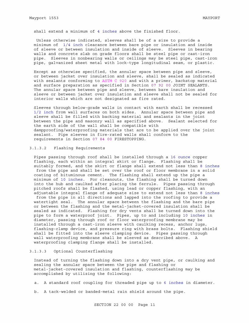
shall extend a minimum of 4 inches above the finished floor.
Unless otherwise indicated, sleeves shall be of a size to provide a minimum of 1/4 inch clearance between bare pipe or insulation and inside of sleeve or between insulation and inside of sleeve. Sleeves in bearing walls and concrete slab on grade floors shall be steel pipe or cast-iron pipe. Sleeves in nonbearing walls or ceilings may be steel pipe, cast-iron pipe, galvanized sheet metal with lock-type longitudinal seam, or plastic.
Except as otherwise specified, the annular space between pipe and sleeve, or between jacket over insulation and sleeve, shall be sealed as indicated with sealants conforming to ASTM C 920 and with a primer, backstop material and surface preparation as specified in Section 07 92 00 JOINT SEALANTS. The annular space between pipe and sleeve, between bare insulation and sleeve or between jacket over insulation and sleeve shall not be sealed for interior walls which are not designated as fire rated.
Sleeves through below-grade walls in contact with earth shall be recessed 1/2 inch from wall surfaces on both sides. Annular space between pipe and sleeve shall be filled with backing material and sealants in the joint between the pipe and masonry wall as specified above. Sealant selected for the earth side of the wall shall be compatible with dampproofing/waterproofing materials that are to be applied over the joint sealant. Pipe sleeves in fire-rated walls shall conform to the requirements in Section 07 84 00 FIRESTOPPING.
3.1.3.2 Flashing Requirements
Pipes passing through roof shall be installed through a 16 ounce copper flashing, each within an integral skirt or flange. Flashing shall be suitably formed, and the skirt or flange shall extend not less than 8 inches from the pipe and shall be set over the roof or floor membrane in a solid coating of bituminous cement. The flashing shall extend up the pipe a minimum of 10 inches. For cleanouts, the flashing shall be turned down into the hub and caulked after placing the ferrule. Pipes passing through pitched roofs shall be flashed, using lead or copper flashing, with an adjustable integral flange of adequate size to extend not less than 8 inches from the pipe in all directions and lapped into the roofing to provide a watertight seal. The annular space between the flashing and the bare pipe or between the flashing and the metal-jacket-covered insulation shall be sealed as indicated. Flashing for dry vents shall be turned down into the pipe to form a waterproof joint. Pipes, up to and including 10 inches in diameter, passing through roof or floor waterproofing membrane may be installed through a cast-iron sleeve with caulking recess, anchor lugs, flashing-clamp device, and pressure ring with brass bolts. Flashing shield shall be fitted into the sleeve clamping device. Pipes passing through wall waterproofing membrane shall be sleeved as described above. A waterproofing clamping flange shall be installed.
3.1.3.3 Optional Counterflashing
Instead of turning the flashing down into a dry vent pipe, or caulking and sealing the annular space between the pipe and flashing or metal-jacket-covered insulation and flashing, counterflashing may be accomplished by utilizing the following:
a. A standard roof coupling for threaded pipe up to 6 inches in diameter.
b. A tack-welded or banded-metal rain shield around the pipe.
SECTION 22 00 00 Page 11

Mayport 1553 MAYPORT
3.1.3.4 Pipe Penetrations
Provide sealants for all pipe penetrations. All pipe penetrations shall be sealed to prevent infiltration of air, insects, and vermin.
3.1.4 Fire Seal
Where pipes pass through fire walls, fire-partitions, fire-rated pipe chase walls or floors above grade, a fire seal shall be provided as specified in Section 07 84 00 FIRESTOPPING.
3.1.5 Supports
3.1.5.1 General
Hangers used to support piping 2 inches and larger shall be fabricated to permit adequate adjustment after erection while still supporting the load. Pipe guides and anchors shall be installed to keep pipes in accurate alignment, to direct the expansion movement, and to prevent buckling, swaying, and undue strain. Piping subjected to vertical movement when operating temperatures exceed ambient temperatures shall be supported by variable spring hangers and supports or by constant support hangers. In the support of multiple pipe runs on a common base member, a clip or clamp shall be used where each pipe crosses the base support member. Spacing of the base support members shall not exceed the hanger and support spacing required for an individual pipe in the multiple pipe run. Threaded sections of rods shall not be formed or bent.
3.1.5.2 Pipe Hangers, Inserts, and Supports
Installation of pipe hangers, inserts and supports shall conform to MSS SP-58 and MSS SP-69, except as modified herein.
a. Types 5, 12, and 26 shall not be used.
b. Type 3 shall not be used on insulated pipe.
c. Type 18 inserts shall be secured to concrete forms before concrete is placed. Continuous inserts which allow more adjustment may be used if they otherwise meet the requirements for type 18 inserts.
d. Type 19 and 23 C-clamps shall be torqued per MSS SP-69 and shall have both locknuts and retaining devices furnished by the manufacturer. Field-fabricated C-clamp bodies or retaining devices are not acceptable.
e. Type 20 attachments used on angles and channels shall be furnished with an added malleable-iron heel plate or adapter.
f. Type 24 may be used only on trapeze hanger systems or on fabricated frames.
g. Type 39 saddles shall be used on insulated pipe 4 inches and larger when the temperature of the medium is 60 degrees F or higher. Type 39 saddles shall be welded to the pipe.
h. Type 40 shields shall:
(1) Be used on insulated pipe less than 4 inches.
SECTION 22 00 00 Page 12
Mayport 1553 MAYPORT
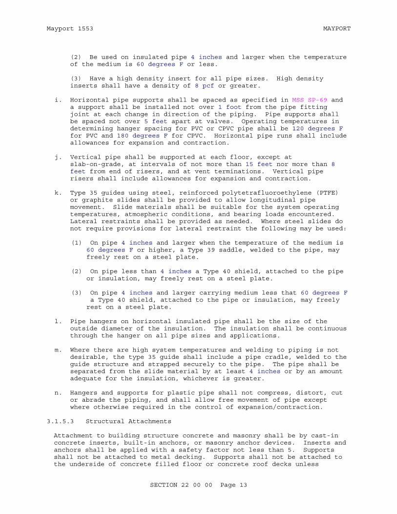
(2) Be used on insulated pipe 4 inches and larger when the temperature of the medium is 60 degrees F or less.
(3) Have a high density insert for all pipe sizes. High density inserts shall have a density of 8 pcf or greater.
i. Horizontal pipe supports shall be spaced as specified in MSS SP-69 and a support shall be installed not over 1 foot from the pipe fitting joint at each change in direction of the piping. Pipe supports shall be spaced not over 5 feet apart at valves. Operating temperatures in determining hanger spacing for PVC or CPVC pipe shall be 120 degrees F for PVC and 180 degrees F for CPVC. Horizontal pipe runs shall include allowances for expansion and contraction.
j. Vertical pipe shall be supported at each floor, except at slab-on-grade, at intervals of not more than 15 feet nor more than 8 feet from end of risers, and at vent terminations. Vertical pipe risers shall include allowances for expansion and contraction.
k. Type 35 guides using steel, reinforced polytetrafluoroethylene (PTFE) or graphite slides shall be provided to allow longitudinal pipe movement. Slide materials shall be suitable for the system operating temperatures, atmospheric conditions, and bearing loads encountered. Lateral restraints shall be provided as needed. Where steel slides do not require provisions for lateral restraint the following may be used:
(1) On pipe 4 inches and larger when the temperature of the medium is 60 degrees F or higher, a Type 39 saddle, welded to the pipe, may freely rest on a steel plate.
(2) On pipe less than 4 inches a Type 40 shield, attached to the pipe or insulation, may freely rest on a steel plate.
(3) On pipe 4 inches and larger carrying medium less that 60 degrees F a Type 40 shield, attached to the pipe or insulation, may freely rest on a steel plate.
l. Pipe hangers on horizontal insulated pipe shall be the size of the outside diameter of the insulation. The insulation shall be continuous through the hanger on all pipe sizes and applications.
m. Where there are high system temperatures and welding to piping is not desirable, the type 35 guide shall include a pipe cradle, welded to the guide structure and strapped securely to the pipe. The pipe shall be separated from the slide material by at least 4 inches or by an amount adequate for the insulation, whichever is greater.
n. Hangers and supports for plastic pipe shall not compress, distort, cut or abrade the piping, and shall allow free movement of pipe except where otherwise required in the control of expansion/contraction.
3.1.5.3 Structural Attachments
Attachment to building structure concrete and masonry shall be by cast-in concrete inserts, built-in anchors, or masonry anchor devices. Inserts and anchors shall be applied with a safety factor not less than 5. Supports shall not be attached to metal decking. Supports shall not be attached to the underside of concrete filled floor or concrete roof decks unless
SECTION 22 00 00 Page 13
Mayport 1553 MAYPORT
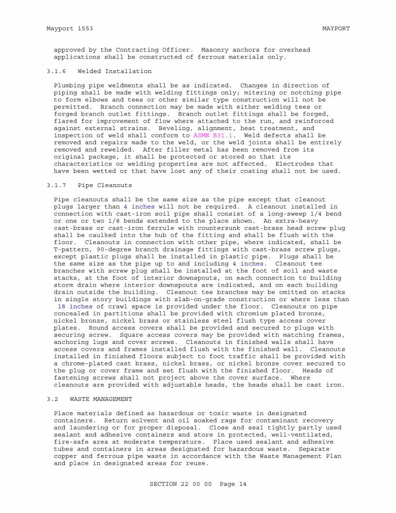
approved by the Contracting Officer. Masonry anchors for overhead applications shall be constructed of ferrous materials only.
3.1.6 Welded Installation
Plumbing pipe weldments shall be as indicated. Changes in direction of piping shall be made with welding fittings only; mitering or notching pipe to form elbows and tees or other similar type construction will not be permitted. Branch connection may be made with either welding tees or forged branch outlet fittings. Branch outlet fittings shall be forged, flared for improvement of flow where attached to the run, and reinforced against external strains. Beveling, alignment, heat treatment, and inspection of weld shall conform to ASME B31.1. Weld defects shall be removed and repairs made to the weld, or the weld joints shall be entirely removed and rewelded. After filler metal has been removed from its original package, it shall be protected or stored so that its characteristics or welding properties are not affected. Electrodes that have been wetted or that have lost any of their coating shall not be used.
3.1.7 Pipe Cleanouts
Pipe cleanouts shall be the same size as the pipe except that cleanout plugs larger than 4 inches will not be required. A cleanout installed in connection with cast-iron soil pipe shall consist of a long-sweep 1/4 bend or one or two 1/8 bends extended to the place shown. An extra-heavy cast-brass or cast-iron ferrule with countersunk cast-brass head screw plug shall be caulked into the hub of the fitting and shall be flush with the floor. Cleanouts in connection with other pipe, where indicated, shall be T-pattern, 90-degree branch drainage fittings with cast-brass screw plugs, except plastic plugs shall be installed in plastic pipe. Plugs shall be the same size as the pipe up to and including 4 inches. Cleanout tee branches with screw plug shall be installed at the foot of soil and waste stacks, at the foot of interior downspouts, on each connection to building storm drain where interior downspouts are indicated, and on each building drain outside the building. Cleanout tee branches may be omitted on stacks in single story buildings with slab-on-grade construction or where less than 18 inches of crawl space is provided under the floor. Cleanouts on pipe concealed in partitions shall be provided with chromium plated bronze, nickel bronze, nickel brass or stainless steel flush type access cover plates. Round access covers shall be provided and secured to plugs with securing screw. Square access covers may be provided with matching frames, anchoring lugs and cover screws. Cleanouts in finished walls shall have access covers and frames installed flush with the finished wall. Cleanouts installed in finished floors subject to foot traffic shall be provided with a chrome-plated cast brass, nickel brass, or nickel bronze cover secured to the plug or cover frame and set flush with the finished floor. Heads of fastening screws shall not project above the cover surface. Where cleanouts are provided with adjustable heads, the heads shall be cast iron.
3.2 WASTE MANAGEMENT
Place materials defined as hazardous or toxic waste in designated containers. Return solvent and oil soaked rags for contaminant recovery and laundering or for proper disposal. Close and seal tightly partly used sealant and adhesive containers and store in protected, well-ventilated, fire-safe area at moderate temperature. Place used sealant and adhesive tubes and containers in areas designated for hazardous waste. Separate copper and ferrous pipe waste in accordance with the Waste Management Plan and place in designated areas for reuse.
SECTION 22 00 00 Page 14

Mayport 1553 MAYPORT
3.3 TABLES
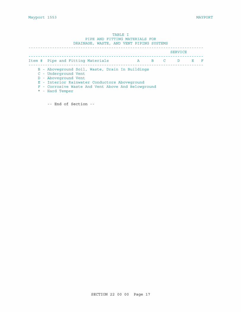
TABLE IPIPE AND FITTING MATERIALS FOR
DRAINAGE, WASTE, AND VENT PIPING SYSTEMS-------------------------------------------------------------------------- SERVICE--------------------------------------------------------------------------Item # Pipe and Fitting Materials A B C D E F--------------------------------------------------------------------------
1 Cast iron soil pipe and fittings, hub X X X X X and spigot, ASTM A 74 with compression gaskets. Pipe and fittings shall be marked with the CISPI trademark.
2 Cast iron soil pipe and fittings hubless, X X X X CISPI 301 and ASTM A 888. Pipe and fittings shall be marked with the CISPI trademark.
3 Cast iron drainage fittings, threaded, X X X ASME B16.12 for use with Item 10
4 Cast iron screwed fittings (threaded) X X ASME B16.4 for use with Item 10
5 Grooved pipe couplings, ferrous and X X X X non-ferrous pipe ASTM A 536 and ASTM A 47/A 47M
6 Ductile iron grooved joint fittings X X X X for ferrous pipe ASTM A 536 and ASTM A 47/A 47M for use with Item 5
7 Bronze sand casting grooved joint X X X X pressure fittings for non-ferrous pipe ASTM B 584, for use with Item 5
8 Wrought copper grooved joint pressure X X pressure fittings for non-ferrous pipe ASTM B 75 C12200, ASTM B 152/B 152M, C11000, ASME B16.22 ASME B16.22 for use with Item 5
9 Malleable-iron threaded fittings, X X galvanized ASME B16.3 for use with Item 10
10 Steel pipe, seamless galvanized, X X X ASTM A 53/A 53M, Type S, Grade B
11 Seamless red brass pipe, ASTM B 43 X X
12 Bronzed flanged fittings, X X
SECTION 22 00 00 Page 15

Mayport 1553 MAYPORT
TABLE IPIPE AND FITTING MATERIALS FOR
DRAINAGE, WASTE, AND VENT PIPING SYSTEMS-------------------------------------------------------------------------- SERVICE--------------------------------------------------------------------------Item # Pipe and Fitting Materials A B C D E F-------------------------------------------------------------------------- ASME B16.24 for use with Items 11 and 14
13 Cast copper alloy solder joint X X pressure fittings, ASME B16.18 for use with Item 14
14 Seamless copper pipe, ASTM B 42 X
15 Cast bronze threaded fittings, X X ASME B16.15
16 Copper drainage tube, (DWV), X* X X* X X ASTM B 306
17 Wrought copper and wrought X X X X X alloy solder-joint drainage fittings. ASME B16.29
18 Cast copper alloy solder joint X X X X X drainage fittings, DWV, ASME B16.23
19 Acrylonitrile-Butadiene-Styrene (ABS) X X X X X X plastic drain, waste, and vent pipe and fittings ASTM D 2661, ASTM F 628
20 Polyvinyl Chloride plastic drain, X X X X X X waste and vent pipe and fittings, ASTM D 2665, ASTM F 891, (Sch 40) ASTM F 1760
21 Process glass pipe and fittings, X ASTM C 1053
22 High-silicon content cast iron pipe X X X and fittings (hub and spigot, and mechanical joint), ASTM A 518/A 518M
23 Polypropylene (PP) waste pipe and X fittings, ASTM D 4101
24 Filament-wound reinforced thermosetting X resin (RTRP) pipe, ASTM D 2996
SERVICE:
A - Underground Building Soil, Waste and Storm Drain
SECTION 22 00 00 Page 16
Mayport 1553 MAYPORT
TABLE IPIPE AND FITTING MATERIALS FOR
DRAINAGE, WASTE, AND VENT PIPING SYSTEMS-------------------------------------------------------------------------- SERVICE--------------------------------------------------------------------------Item # Pipe and Fitting Materials A B C D E F-------------------------------------------------------------------------- B - Aboveground Soil, Waste, Drain In Buildings C - Underground Vent D - Aboveground Vent E - Interior Rainwater Conductors Aboveground F - Corrosive Waste And Vent Above And Belowground * - Hard Temper
-- End of Section --
SECTION 22 00 00 Page 17

Mayport 1553 MAYPORT
SECTION 23 37 13.00 40
DIFFUSERS, REGISTERS, AND GRILLS05/10
PART 1 GENERAL
1.1 REFERENCES
The publications listed below form a part of this specification to the extent referenced. The publications are referred to within the text by the basic designation only.
AMERICAN SOCIETY OF HEATING, REFRIGERATING AND AIR-CONDITIONING ENGINEERS (ASHRAE)
ASHRAE 113 (2009) Method of Testing for Room Air Diffusion
ASHRAE EQUIP IP HDBK (2008; Errata 1 2010) Handbook, HVAC Systems and Equipment (IP Edition)
ASHRAE FUN IP (2009; Errata 2010) Fundamentals Handbook, I-P Edition
1.2 PERFORMANCE REQUIREMENTS
Certify air diffusion devices having been tested and rated in accordance with ASHRAE EQUIP IP HDBK, Chapter 17; ASHRAE FUN IP, Chapter 31; and ASHRAE 113, where such certification is required.
Submit equipment and performance data for air-diffusion devices consisting of sound data in terms of Noise Criteria (NC) index for the capacity range of the device.
1.3 SUBMITTALS
Government approval is required for submittals with a "G" designation; submittals not having a "G" designation are for Contractor Quality Control approval. Submit the following in accordance with Section 01 33 00 SUBMITTAL PROCEDURES:
SD-03 Product Data
Submit Equipment and Performance Data G for air-diffusion devices in accordance with paragraph entitled, "Performance Requirements," of this section.
PART 2 PRODUCTS
2.1 AIR-DIFFUSION DEVICE CONSTRUCTION
Preclude flutter, rattle, or vibration on air-diffusion device construction and mounting. Modify devices and provide accessories necessary for mounting in indicated surface construction.
Select color from manufacturer's standard color chart which indicate the
SECTION 23 37 13.00 40 Page 1
Mayport 1553 MAYPORT
manufacturer's standard color selections and finishes for air-diffusion devices.
Provide supply diffusers with damper. Ensure dampers are extracting-splitter type, except as otherwise indicated.
Provide gaskets for supply-terminal air devices mounted in finished surfaces.
Include within the material, equipment, and fixture lists the manufacturer's style or catalog numbers, specification and drawing reference numbers, warranty information, and fabrication site information.
2.2 TYPES OF AIR-DIFFUSION DEVICES
2.2.1 Type Ceiling Supply
Provide type DSA supply diffuser, square with four expanding flared members to provide radically diffused discharge air. Arrange flared members to provide a minimum of four air paths. Include pattern adjustments horizontal, vertical projection, and an intermediate position or range.
Provide a baked enamel finish.
Provide aluminum construction.
2.2.2 Type Return Air
Provide type GR return grills, single deflection type with fixed face bars.
Provide grills installed in vertical surfaces with horizontal face bars set downward at 35 degrees from vertical.
Provide grills installed in horizontal surfaces with face bars straight and parallel to short dimension.
Provide a baked enamel finish.
Provide aluminum construction.
2.2.3 Type Sidewall Supply
Provide type RS supply register, double-deflection type, with adjustable face bars parallel to short dimension and adjustable rear bars parallel to long dimension with opposed-blade type dampers.
Provide a baked enamel finish.
Provide aluminum construction.
PART 3 EXECUTION
3.1 INSTALLATION
Install equipment as indicated and specified and in accordance with manufacturer's recommendations.
SECTION 23 37 13.00 40 Page 2
Mayport 1553 MAYPORT
3.1.1 Operations and Maintenance Manuals
Provide operation and maintenance manuals consistent with manufacturer's standard brochures, schematics, printed instructions, general operating procedures and safety precautions.
-- End of Section --
SECTION 23 37 13.00 40 Page 3

Mayport 1553 MAYPORT
SECTION 23 81 23.00 20
COMPUTER ROOM AIR CONDITIONING UNITS02/10
PART 1 GENERAL
1.1 REFERENCES
The publications listed below form a part of this specification to the extent referenced. The publications are referred to within the text by the basic designation only.
AIR-CONDITIONING, HEATING AND REFRIGERATION INSTITUTE (AHRI)
AHRI 410 (2001; Addendum 2002) Forced-Circulation Air-Cooling and Air-Heating Coils
AMERICAN SOCIETY OF HEATING, REFRIGERATING AND AIR-CONDITIONING ENGINEERS (ASHRAE)
ANSI/ASHRAE 15 & 34 (2007; Std 15 Errata 2007, 2009, & Addenda a-i; Std 34 Errata 2007, 2008, Addenda a-v, x-ae) ANSI/ASHRAE Standard 15-Safety Standard for Refrigeration Systems and ANSI/ASHRAE Standard 34-Designation and Safety Classification of Refrigerants
ASHRAE 52.2 (2007; Addenda b 2008; Errata 2009) Method of Testing General Ventilation Air-Cleaning Devices for Removal Efficiency by Particle Size
ASHRAE 90.1 - IP (2007; Supplement 2008; Addenda r 2009) Energy Standard for Buildings Except Low-Rise Residential Buildings
ASME INTERNATIONAL (ASME)
ASME B16.22 (2001; R 2005) Standard for Wrought Copper and Copper Alloy Solder Joint Pressure Fittings
ASME B16.26 (2006) Standard for Cast Copper Alloy Fittings for Flared Copper Tubes
ASME B31.1 (2007; Addenda a 2008; Addenda b 2009) Power Piping
ASME B31.5 (2006) Refrigeration Piping and Heat Transfer Components
ASME BPVC (2007) Boiler and Pressure Vessels Code
ASTM INTERNATIONAL (ASTM)
ASTM B 280 (2008) Standard Specification for Seamless Copper Tube for Air Conditioning and
SECTION 23 81 23.00 20 Page 1
Mayport 1553 MAYPORT
Refrigeration Field Service
ETL TESTING LABORATORIES (ETL)
ETL DLP (updated continuously) Directory of ETL Listed Products
NATIONAL FIRE PROTECTION ASSOCIATION (NFPA)
NFPA 70 (2008; TIA 08-1) National Electrical Code
NFPA 90A (2009; Errata 09-1) Standard for the Installation of Air Conditioning and Ventilating Systems
UNDERWRITERS LABORATORIES (UL)
UL Elec Equip Dir (2009) Electrical Appliance and Utilization Equipment Directory
1.2 SYSTEM DESCRIPTION
Provide new computer room air conditioning units (CRACU) complete and ready for operation.
1.3 SUBMITTALS
Government approval is required for submittals with a "G" designation; submittals not having a "G" designation are for Contractor Quality Control approval. The following shall be submitted in accordance with Section 01 33 00 SUBMITTAL PROCEDURES:
SD-03 Product Data
Computer room air conditioning units; G
SD-08 Manufacturer's Instructions
Installation manual for each type of CRACU
SD-10 Operation and Maintenance Data
Computer room air conditioning units
1.4 OZONE DEPLETION FACTOR
Equipment using refrigerants R-11, R-12, R-113, R-114, R-115, R-500, or refrigerants with ozone depletion factor (ODF) greater than 0.05, or refrigerants containing CFCs or Halons shall not be permitted. Refrigerant shall be an approved alternative refrigerant per EPA's Significant New Alternative Policy (SNAP) listing. Use HCFC-22 refrigerant.
PART 2 PRODUCTS
2.1 COMPUTER ROOM AIR CONDITIONING UNITS (CRACU)
ANSI/ASHRAE 15 & 34. Provide self-contained units, designed, and factory assembled, and factory tested. Unit shall be listed in UL Elec Equip Dir or ETL DLPfor computer room application. Equipment shall be in accordance
SECTION 23 81 23.00 20 Page 2
Mayport 1553 MAYPORT
with ASHRAE 90.1 - IP,. Unit shall include room cabinet and frame, floor stand, fan section, filter section, cooling coil, reheat coil, humidifier, compressors, condensers, controls, and, interconnecting piping internal to the CRACU.
2.1.1 Cabinet and Frame
2.1.1.1 Unit Cabinet
Unit frame shall be minimum 14 gage welded steel tubes or steel angles and shall be mill-galvanized or coated with an epoxy finish, or an approved manufacturer's standard finish, if equivalent.
Exterior panels shall be furniture grade steel sheet, minimum of 20 gage, mill-galvanized or coated with a corrosion-inhibiting epoxy finish, or an approved equivalent finish. Mill rolled structural steel shall be hot-dip galvanized or primed and painted. Cut edges, burns and scratches in hot-dip galvanized surfaces shall be coated with galvanizing repair coating.
Provide removable panel for access to controls without interrupting airflow. Panels shall be gasketed to prevent air leakage under system operating pressure and shall be removable for service access without the use of special tools. Condensate pans shall be minimum 22 gage non-corroding, double-sloped, and shall be piped to drain.
Exterior surfaces of cabinets constructed of mill-galvanized steel shall be finished by the manufacturer's standard enamel finish in the indicated color.
CRACU manufacturer's standard cabinet materials and finishes will be acceptable if considered equivalent to the above requirements by the Contracting Officer.
2.1.1.2 Cabinet Interiors Sound Attenuation
Provide a factroy-installed sound attenuation system in the interior of the CRACU cabinet.
CRACU cabinet panels interior shall be provided with one inch of 1 1/2 pound per cubic foot neoprene-coated fiber glass insulation on interior of cabinet panels. Insulation shall be applied to the cabinet panels with 100 percent adhesive coverage and both the insulation and the adhesive shall conform to NFPA 90A.
Fans and compressors located in the CRACU interior cabinet shall be provided with vibration isolators between their respective support frames and the cabinet framing.
CRACU manufacturer's standard interior cabinet sound attenuation materials and finishes will be acceptable if considered equivalent to the above requirements by the Contracting Officer.
2.1.2 Fan Section
Fans which force air through coils into computer rooms shall have belt drives and adjustable sheaves sized to ensure achievement of design air flow by field adjustments. Fan system design shall be such that design air flow shall be achieved at the midpoint of sheave adjustment.
SECTION 23 81 23.00 20 Page 3

Mayport 1553 MAYPORT
The supply air fan shall be AMCA certified, double-inlet/double-width, and equipped with forward-curved blades wheel. The supply air fan shall be statically and dynamically balanced and equipped with V-belt drive. The fan shall have self-aligning, permanently lubricated ball bearings with a minimum life span of 100,000 hours.
Provide V-belt drive sized for 200 percent of the motor nameplate rating. Fan speed shall be adjustable with cast iron variable pitch pulleys. Sheaves shall be within the middle one third of the sheave adjustment range.
The fan motor shall be drip-proof with NEMA rated frame, inherent overload protection, and sliding adjustable motor base.
2.1.3 Cooling Coil
Provide AHRI 410 coils and slope for drainage. Coil shall be constructed of seamless copper tubes with plate aluminum fins. Indoor and outdoor coils shall be matched and from same manufacturer. Use a low sensible heat ratio for more moisture removal. Each coil, in the production process, shall be individually tested at 320 psi with compressed air under water and verified to be air tight. Provide DX coil complete with a distributor and thermostatic expansion valve with external equalizer.Provide condensate drain pan with nonferrous connections and internal trap.
2.1.4 Filters
Provide UL listed2 inches thick deep pleated fiberglass throwaway type filters. Provide filtration media with a Minimum Efficiency Reporting Value (MERV) of 6 as determined by ASHRAE 52.2. Provide one complete spare filter bank set for installation prior to final acceptance.
2.1.5 Reheat Coil
Provide AHRI 410 reheat coils and slope for drainage. Provide coil constructed of seamless copper tubes with plate aluminum fins. Each coil, in the production process, shall be individually tested at 320 psi with compressed air under water and verified to be air tight.
2.1.6 Humidifier
Humidifier section shall include liquid-level control, emergency overflow and automatic water supply system factory pre-piped for final connection. Provide evaporator pan with water high level and low level alarms. Arrange system to be cleanable and serviceable.
Provide infrared type humidifier, including high intensity quartz lamps mounted above and out of water supply.
2.1.7 Refrigeration System
Provide compressors complete with vibration isolation, suction and discharge service valves, high and low pressure safety switches, and built-in overload protection. Provide refrigeration circuits including hot gas mufflers, liquid-line filter-drier, refrigerant sight glass and moisture indicator, externally equalized expansion valve, and liquid-line solenoid valve factory connected with refrigeration copper tubing.
SECTION 23 81 23.00 20 Page 4

Mayport 1553 MAYPORT
2.1.7.1 Compressors
Provide single scroll compressors.
2.1.7.2 Refrigerant Tubing
Field-installed refrigerant tubing for split systems shall be ASTM B 280, cleaned, dehydrated, and sealed. Further, provide ASME B16.22 solder joint refrigerant fittings and adapters with silver brazing alloy solder and silver brazing alloy flux. During brazing operations bleed a small amount of dry oil-free nitrogen continuously through the refrigerant tubing. If required for connections to equipment, provide ASME B16.26 flared fittings.
2.1.8 Condenser
2.1.8.1 Liquid-cooled Condenser
Provide cleanable, cast iron or steel shell and copper tubes, water-cooled condenser with removable cast iron or steel heads. The condenser shall be constructed in accordance with ASME BPVC. As an option, a coaxial (copper tube-in-copper tube) type water-cooled condenser may be provided.
2.1.9 Space Temperature Control System
Provide microprocessor control system integral with unit including electronic control center, control valves, sensors, wiring, and other appurtenances for workable system. Provide access panel or door in front of unit.
Isolate electronic control center from conditioned airstream to allow service while system is in operation. Provide control sensors in unit for cooling, dehumidifying, and humidifying. High-voltage circuits in system shall have individual leg overload protection. Starters, contactors, and relays shall be controlled by 24 volt control circuit.
High-voltage circuit components shall be protected by safety lock, dead-front panel. Mount nonautomatic, molded-case circuit breaker in high-voltage section of electrical panel. Operating mechanism shall prevent access to high-voltage electrical components until switched to "OFF" position.
Include the following control capabilities:
a. Capable of changing the set points and sensitivity of the space and humidity along with their low and high alarm points.
b. Logging capability of the last 10 alarms and run time.
c. Diagnostics
d. Refrigerant compressor sequencing
2.1.10 Alarm Panel System
Provide unit with cabinet-mounted alarm panel which shall monitor high and low space temperature, high and low space humidity, dirty filters, loss of airflow, loss of water flow, compressor high head pressure, and humidifier problems. Provide field accessible local audible alarm with silence
SECTION 23 81 23.00 20 Page 5

Mayport 1553 MAYPORT
pushbutton. CRACUs shall have local devices which provide signals for remote audible and visual alarming capability for the above specified alarm conditions.
2.2 ELECTRICAL
2.2.1 Electrical Motors, Controllers, Contactors, and Disconnects
Furnish with respective pieces of equipment. Motors, controllers, contactors, and disconnects shall conform to Section 26 20 00 INTERIOR DISTRIBUTION SYSTEM, as modified and supplemented by this section. Provide electrical connections under Section 26 20 00 INTERIOR DISTRIBUTION SYSTEM. Provide controllers and contactors with maximum of 120-volt control circuits, and auxiliary contacts for use with controls furnished. Motors shall be variable-speed. When motors and equipment furnished are larger than sizes indicated, the cost of providing additional electrical service and related work shall be included under this section.
2.3 HVAC WATER PIPING AND METAL DUCTWORK
Requirements for HVAC water piping and metal ductwork is specified in Section 23 64 26 CHILLED, CHILLED-HOT AND CONDENSER WATER PIPING AND ACCESSORIES.
2.4 SOURCE QUALITY CONTROL
2.4.1 Manufacturer's Factory Test Plans
2.4.1.1 Tested Variables
Plans shall provide for air side testing which includes verification of the airflow,fan drive motor KW, amperage and RPM; and fan RPM. Provide entering air temperatures equal to those indicated on the CRACU schedules.
PART 3 EXECUTION
3.1 INSTALLATION
3.1.1 CRACU System
Installation of each CRACU system including equipment, materials, installation, workmanship, fabrication, assembly, erection, examination, inspection, and testing, shall be in accordance with ASME B31.1, ASME B31.5, NFPA 70, as modified and supplemented by the requirements of this section and the CRACU manufacturer's recommendations.
3.1.2 Installation Instructions
Provide a manufacturer's installation manual for each type of CRACU.
3.2 FIELD QUALITY CONTROL
Upon completion and before final acceptance of work, test each CRACU subsystem in service to demonstrate compliance with the contract requirements, including field testing specified below. Adjust controls and balance systems prior to final acceptance of completed systems. Test controls through every cycle of operation. Test safety controls to demonstrate performance of required function. Correct defects in work provided by Contractor and repeat tests. Furnish steam, fuel, water,
SECTION 23 81 23.00 20 Page 6

Mayport 1553 MAYPORT
electricity, instruments, connecting devices, and personnel for tests. Flush and clean piping before placing in operation. Clean equipment, piping, strainers, and ducts. Prior to commencement of field testing, remove all filters and provide new filters.
3.3 FIELD TESTING
Provide field test plans, field test schedules, field tests and field test reports on each of the CRACUs. Field test each CRACU for Contracting Officer acceptance in accordance with the CRACU manufacturer's approved field test plan.
3.3.1 Manufacturer's Field Test Plans
3.3.1.1 Coordinated Testing
Indicate in each field test plan when work required by this section requires coordination with test work required by other specification sections. Furnish test procedures for the simultaneous or integrated testing of: CRACU controls which interlock and interface with controls factory prewired.
3.3.1.2 Prerequisite Testing
Each CRACU for which performance testing is dependent upon the completion of the work covered by Section 23 05 93 TESTING, ADJUSTING AND BALANCING must have that work completed as a prerequisite to testing work under this section. Indicate in each field test plan when such prerequisite work is required.
3.3.1.3 Test Procedure
Indicate in each field test plan the CRACU manufacturer's published start-up, and field acceptance test procedures. Include in each test plan a detailed step-by-step procedure for testing automatic controls provided by the manufacturer.
Procedures shall be structured to test the controls through all modes of control to confirm that the controls are performing with the intended sequence of control.
Controllers shall be verified to be properly calibrated and have the proper set point to provide stable control of their respective equipment.
3.3.1.4 Tested Variables
Plans shall provide for air side testing which includes verification of the airflow, fan drive motor KW, amperage and RPM; and fan RPM. Provide entering air temperatures equal to those indicated on the CRACU schedules.
3.3.1.5 Field Test Reporting Forms
Each test shall include the required test reporting forms to be completed by the Contractor's testing representatives.
3.3.2 Manufacturer's Test Representative
Furnish a factory trained field test representative authorized by the CRACU manufacturer to oversee the complete execution of the field testing. This
SECTION 23 81 23.00 20 Page 7
Mayport 1553 MAYPORT
test representative shall also review, approve, and sign the completed field test report. Signatures shall be accompanied by the person's name typed.
Submit credentials of the manufacturer's field test representative proposed, including current telephone number, to the Contracting Officer for review and approval.
-- End of Section --
SECTION 23 81 23.00 20 Page 8

Mayport 1553 MAYPORT
SECTION 23 82 00.00 20
TERMINAL HEATING AND COOLING UNITS11/08
PART 1 GENERAL
1.1 REFERENCES
The publications listed below form a part of this specification to the extent referenced. The publications are referred to within the text by the basic designation only.
AMERICAN SOCIETY OF HEATING, REFRIGERATING AND AIR-CONDITIONING ENGINEERS (ASHRAE)
ASHRAE 33 (2000) Method of Testing Forced Circulation Air Cooling and Air Heating Coils
ASTM INTERNATIONAL (ASTM)
ASTM A 123/A 123M (2009) Standard Specification for Zinc (Hot-Dip Galvanized) Coatings on Iron and Steel Products
ASTM A 653/A 653M (2009a) Standard Specification for Steel Sheet, Zinc-Coated (Galvanized) or Zinc-Iron Alloy-Coated (Galvannealed) by the Hot-Dip Process
ASTM B 117 (2009) Standing Practice for Operating Salt Spray (Fog) Apparatus
ASTM D 1654 (2008) Evaluation of Painted or Coated Specimens Subjected to Corrosive Environments
NATIONAL ELECTRICAL MANUFACTURERS ASSOCIATION (NEMA)
NEMA ICS 2 (2000; Errata 2006; R 2005; Errata 2008) Standard for Controllers, Contactors, and Overload Relays Rated 600 V
NEMA ICS 6 (1993; R 2001; R 2006) Standard for Enclosures
NEMA MG 1 (2007; Errata 2008) Standard for Motors and Generators
NATIONAL FIRE PROTECTION ASSOCIATION (NFPA)
NFPA 211 (2010) Standard for Chimneys, Fireplaces, Vents, and Solid Fuel-Burning Appliances
NFPA 54 (2009) National Fuel Gas Code
NFPA 70 (2008; AMD 1 2008) National Electrical Code
SECTION 23 82 00.00 20 Page 1

Mayport 1553 MAYPORT
NFPA 90A (2009; Errata 09-1) Standard for the Installation of Air Conditioning and Ventilating Systems
NFPA 90B (2009) Standard for the Installation of Warm Air Heating and Air Conditioning Systems
NFPA 91 (2010) Standard for Exhaust Systems for Air Conveying of Vapors, Gases, Mists and Noncombustible Particulate Solids
1.2 RELATED REQUIREMENTS
Section 23 03 00.00 20 BASIC MECHANICAL MATERIALS AND METHODS, applies to this section with additions and modifications specified herein.
1.3 SUBMITTALS
Government approval is required for submittals with a "G" designation; submittals not having a "G" designation are for Contractor Quality Control approval. The following shall be submitted in accordance with Section 01 33 00 SUBMITTAL PROCEDURES:
SD-03 Product Data
Unit heaters
SD-10 Operation and Maintenance Data
Unit heaters
Submit in accordance with Section 01 78 23 OPERATION AND MAINTENANCE DATA.
PART 2 PRODUCTS
2.1 UNIT HEATERS
Self-contained and factory assembled, propeller or centrifugal fan with capacities expressed as Btu per hour output and cubic foot-per-minute air delivery, operating conditions, and mounting arrangements as indicated. Average fan bearing life shall be minimum 200,000 hours at operating conditions. Provide fan motor with direct drive. Construct fan-guard motor mount of steel wire. Equip each heater with individually adjustable package discharge louver. Louvers may be substituted by discharge cones or diffusers. Provide thermostats as indicated. Furnish circuit breaker disconnect switch.
2.1.1 Hot-Water Unit Heater
ASHRAE 33 tested for heating coils; UL listed for motor and controls.
2.1.1.1 Casing
Minimum 20 gage steel with removable access panels or means to remove, service, and maintain major components.
SECTION 23 82 00.00 20 Page 2

Mayport 1553 MAYPORT
2.1.1.2 Coil
Fin-and-tube coil constructed of copper tubes and aluminum fins. Use maximum design pressure of hot water at 225 psig and 325 degrees F.
2.1.1.3 Controls
Automatic controls of on-off-auto system.
2.1.2 Electric Unit Heater
UL listed; wattage, voltage, phase, and number of steps as indicated. Provide control-circuit terminals and single source of power supply. Heater 5 Kw and larger shall be three-phase, with load balanced on each of the three phases. Limit leaving air temperature below 140 degrees F at 60 degrees F entering air.
2.1.2.1 Casing
Minimum 21 gage steel.
2.1.2.2 Heating Element
Nickel-chromium heating wire element, free from expansion noise and 60 Hz hum. Embed element in magnesium-oxide insulating refractory. Seal element in high-mass steel or corrosion-resisting metallic sheath with fins. Enclose element ends in terminal box. Space fins at maximum six fins per inch. Limit fin surface temperature 550 degrees Fat any point during normal operation.
2.1.2.3 Controls
Include limit controls for thermal overheat protection of heaters. For remote thermostatic operation, provide contactor rated for 100,000 duty cycles. Provide a control transformer to supply 120-volt thermostat control circuit for each heater. Provide room thermostat for pilot duty.
2.1.2.4 Wiring
Completely factory-prewired to terminal strips, ready to receive branch circuit and control connections for 140 degrees Fcopper wiring.
2.1.2.5 AccessoriesProvide fan switching devices to independently operate fan motor for summer ventilation and winter heat recovery.
2.2 MOTOR AND STARTER
NEMA MG 1, and NEMA ICS 2, and NEMA ICS 6, respectively. Provide continuous-duty motor with built-in automatic reset thermal overload protection. For motor 1/2 hp and larger, use three-phase. Provide single-phase motor of permanent split capacitor or capacitor start. Limit motor speed at 1800 r/min. Wire motor to heater power supply source.
2.3 NOISE, VIBRATION AND SEISMIC CONTROLS
Section 22 05 48.00 20 MECHANICAL SOUND VIBRATION AND SEISMIC CONTROL.
SECTION 23 82 00.00 20 Page 3

Mayport 1553 MAYPORT
2.4 HOT WATER PIPING SYSTEM
Section 23 21 13.00 20 LOW TEMPERATURE WATER LTW HEATING SYSTEMS.
2.5 SOURCE QUALITY CONTROL
Special protection is not required for equipment that has a zinc coating conforming to \&ASTM A 123/A 123M and ASTM A 653/A 653M&\. Otherwise, protect affected equipment items by manufacturers' corrosion-inhibiting coating or paint system that has proved capable of withstanding salt-spray test in accordance with ASTM B 117. Test indoor and outdoor equipment for 125 hours; test outdoor equipment used in a marine atmosphere for 500 hours. For each specimen, perform a scratch test as defined in ASTM D 1654.
PART 3 EXECUTION
3.1 INSTALLATION
Install equipment where indicated and as recommended by manufacturer's recommendations, NFPA 54, NFPA 90A, NFPA 90B, NFPA 91 and NFPA 211.
3.1.1 Suspensions of Equipment
Provide equipment supports including beam clamps, turnbuckles and twist links or weld-wire chains, wire ropes with rope clips and rope thimbles, threaded-eye rod hangers with lock nuts and heat-duct hangers, threaded-eye bolts with expansion screws, brackets, platform and mounting frame, and vibration isolators. Locate equipment in such a manner that working space is available for servicing, such as vacuum pump and burner removal, access to automatic controls, and lubrication. Provide electrical isolation of dissimilar metals. Clean interior of casings or cabinets before and after completion of installation.
3.1.2 Vents
NFPA 54 and NFPA 211. Provide vents with weatherproofing flashings in accordance with Section 07 57 13 FLASHING AND SHEET METAL.
3.1.3 Electrical Work
NFPA 70 and Division 16, "Electrical Work." When replacing original control wires, provide No. 16 AWG with minimum 105 degrees C insulation.
3.2 FIELD QUALITY CONTROL
Administer, schedule, and conduct specified tests. Furnish personnel, instruments and equipment for such tests. Correct defects and repeat the respective inspections and tests. Conduct inspections and testing in the presence of the Contracting Officer.
3.2.1 Test Instruments and Apparatus
Provide instruments and apparatus currently certified as being accurate to within one percent of their full scale. Use gages with a maximum scale between 1 1/2 and 2 times test pressure.
3.2.2 Field Inspection
Prior to initial operation, inspect equipment installation to ensure that
SECTION 23 82 00.00 20 Page 4

Mayport 1553 MAYPORT
indicated and specified requirements have been met.
-- End of Section --
SECTION 23 82 00.00 20 Page 5
Mayport 1553 MAYPORT
SECTION 23 82 16
AIR COILS08/08
PART 1 GENERAL
1.1 REFERENCES
The publications listed below form a part of this specification to the extent referenced. The publications are referred to within the text by the basic designation only.
AIR-CONDITIONING, HEATING AND REFRIGERATION INSTITUTE (AHRI)
AHRI 410 (2001; Addendum 2002) Forced-Circulation Air-Cooling and Air-Heating Coils
ASTM INTERNATIONAL (ASTM)
ASTM A 653/A 653M (2009a) Standard Specification for Steel Sheet, Zinc-Coated (Galvanized) or Zinc-Iron Alloy-Coated (Galvannealed) by the Hot-Dip Process
1.2 SUBMITTALS
Government approval is required for submittals with a "G" designation; submittals not having a "G" designation are for Contractor Quality Control approval. Submit the following in accordance with Section 01 33 00 SUBMITTAL PROCEDURES:
SD-02 Shop Drawings
Submit Connection diagrams indicating the relations and connections of the following items. Indicate the general physical layout of all controls, and internal tubing and wiring details on the drawings.
SD-03 Product Data
Submit Manufacturer's catalog data for the following coil types indicating, when applicable, coil pressure and temperature ratings, coil casings, headers, tubing, circuiting, and drainable coils.
Hot-Water Heating
SD-10 Operation and Maintenance Data
Submit Operation and Maintenance Manuals in accordance with paragraph entitled, "Operation and Maintenance," of this section.
1.3 GENERAL REQUIREMENTS
Section 23 00 00 AIR SUPPLY, DISTRIBUTION, VENTILATION, AND EXHAUST SYSTEMS applies to work specified in this section.
SECTION 23 82 16 Page 1

Mayport 1553 MAYPORT
Submit Fabrication Drawings for coil units consisting of fabrication and assembly details to be performed in the factory.
Submit Record Drawings for coil systems providing current factual information including deviations from, and amendments to, the drawings and concealed and visible changes in the work.
1.4 LABEL
Provide coils that bear the ARI certification seal indicating compliance with AHRI 410.
PART 2 PRODUCTS
2.1 GENERAL
2.1.1 Coil Pressure and Temperature Ratings
Provide coils that are designed for the following fluid operating pressures and temperatures.
Pressure Temperature Service (psi) (Degrees F)
Hot water 200 250
Air-pressure test coils under water at the following minimum pressures:
Pressure Service (psi)
Hot water 250
2.1.2 Coil Casings
Provide coil casing that is mill-galvanized 16-gage, minimum, sheet metal with not less than 1.25 ounces of zinc per square foot of two-sided metal surface conforming to ASTM A 653/A 653M. Provide casing that is flanged on four sides for bolted assembly, except as otherwise specified.
Where coils are stacked, provide casing that is of double-bend construction.
Provide duct-mounted reheat coil casings not over 36 inches in length that are fabricated from a minimum 20-gage galvanized steel conforming to above specified requirements; provide casings that are flanged or suitable for drive-slip assembly.
Provide coil mounting within housing that is either fixed or slide-out type, except as otherwise specified. Provide slide-out type coils for ceiling-suspended package units, and for other package units whose capacity exceeds 15,000 cubic feet per minute.
2.1.3 Coil Tubing
Provide coils that are constructed of copper tubing with aluminum or copper fins.
SECTION 23 82 16 Page 2
Mayport 1553 MAYPORT
Provide coil tubes in water and volatile refrigerant service that are parallel and that have sufficient intermediate full coil depth supports to prevent sagging of unsupported span due to working fluid pressures and temperatures and summer and winter coil-ambient conditions. Sagging is unacceptable if tube centerline is displaced by more than 3/16 inch from centerline of tube connection at outlet header when coils are more than two rows deep and when installed in accordance with the manufacturer's instructions. Provide adequate provisions for expansion and contraction to preclude sagging and distortion under thermal loads applied in indicated or specified service. Slope tubes to be free draining.
Provide maximum heating-coil face tube spacing of 3 inches on center for 1-inch outside-diameter (od) tubes, 2 inches for 3/4-inch od tubes, and 1-1/2 inches for 5/8-inch od tubes.
Provide tubes that are straight, with turns made through headers or return U-bends, and connections and joints brazed, except as otherwise specified.
Ensure coil tube material is seamless deoxidized copper.
2.1.4 Drainable Coils
Provide drainable coils that are capable of being purged free of water with compressed air.
2.2 COIL TYPES
2.2.1 Hot-Water Heating
For Type HA, provide continuous circuit type, limited to two rows depth.
PART 3 EXECUTION
3.1 INSTALLATION
Install coils in accordance with the manufacturer's recommendations.
Submit Installation Drawings for coil systems. Indicate overall physical features, dimensions, ratings, service requirements, equipment weights and layout and arrangement details of equipment room on drawings.
3.2 TESTS
Provide final test reports to the Contracting Officer. Provide reports with a cover letter/sheet clearly marked with the System name, Date, and the words "Final Test Reports - Forward to the Systems Engineer/Condition Monitoring Office/Predictive Testing Group for inclusion in the Maintenance Database."
3.3 OPERATION AND MAINTENANCE
Submit 6 copies of the Operation and Maintenance Manuals 30 calendar days
SECTION 23 82 16 Page 3

Mayport 1553 MAYPORT
prior to testing the coil systems. Update and resubmit data for final approval no later than 30 calendar days prior to contract completion.
-- End of Section --
SECTION 23 82 16 Page 4