awwa butterfly valves technical specifications · awwa butterfly valves technical specifications...
TRANSCRIPT
AWWA BUTTERFLY VALVESTECHNICAL SPECIFICATIONS
BULLETIN 43.00-2
SEPTEMBER 2009
2
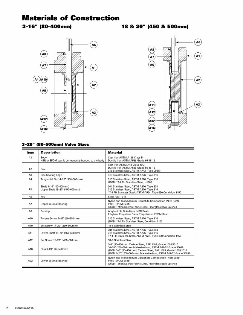
3–16" (80–400mm) 18 & 20" (450 & 500mm)
3–20" (80–500mm) Valve Sizes
A6
A1
A2
A3
A16
A32
A5
A10A4
A7
A8
A6
A1
A2
A3
A16
A32
A5
A11
A12
A7
A8
Materials of Construction
A1 Body Cast Iron ASTM A126 Class B NBR or EPDM seat is permanently bonded to the body Ductile Iron ASTM A536 Grade 65-45-12
A2
Disc
Cast Iron ASTM A48 Class 40C Ductile Iron ASTM A536 Grade 65-45-12 316 Stainless Steel, ASTM A743, Type CF8M
A3 Disc Seating Edge 316 Stainless Steel, ASTM A276, Type 316
A4 Tangential Pin 14–20" (350–500mm) 316 Stainless Steel, ASTM A276, Type 316 (250B) 17-4 PH Stainless Steel, H1100
A5
Shaft 3–16" (80–400mm) 304 Stainless Steel, ASTM A276, Type 304 Upper Shaft 18–20" (450–600mm) 316 Stainless Steel, ASTM A276, Type 316 17-4 PH Stainless Steel, ASTM A564, Type 630 Condition 1150
A6 Key Steel AISI 1018
Nylon and Molybdenum Disulphite Composition (NBR Seat) A7 Upper Journal Bearing PTFE (EPDM Seat) (250B) Teflon/Dacron Fabric Liner, Fiberglass back-up shell
A8 Packing Acrylonitrile Butadiene (NBR Seat) Ethylene Propylene Diene Terpolymer (EPDM Seat)
A10 Torque Screw 3–12" (80–300mm) 316 Stainless Steel, ASTM A276, Type 316 (250B) 17-4 PH Stainless Steel, Condition 1100
A10 Set Screw 14–20" (350–500mm) 18–8 Stainless Steel
304 Stainless Steel, ASTM A276, Type 304 A11 Lower Shaft 18–20" (450–600mm) 316 Stainless Steel, ASTM A276, Type 316 17-4 PH Stainless Steel, ASTM A564, Type 630 Condition 1150
A12 Set Screw 18–20" ( 450–500mm) 18–8 Stainless Steel
3–8" (80–200mm) Carbon Steel, SAE J403, Grade 1008/1010
A16
Plug 3–20" (80–500mm) 10–20" (250–500mm) Malleable Iron, ASTM A47-52 Grade 35018
(250B, 3–6" (80–150mm)) Carbon Steel, SAE J403, Grade 1008/1010 (250B, 8–20" (200–500mm)) Malleable Iron, ASTM A47-52 Grade 35018
Nylon and Molybdenum Disulphide Composition (NBR Seat) A32 Lower Journal Bearing PTFE (EPDM Seat) (250B) Teflon/Dacron Fabric Liner, Fiberglass back-up shell
Item Description Material
© 2009 DeZURIK
See Detail B
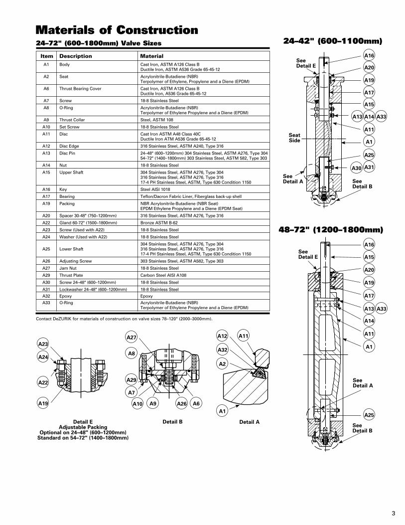
Materials of Construction24–42" (600–1100mm)
48–72" (1200–1800mm)
A16
A20
A19
A24
A22
A19
A27
A8
A29
A7
A12
A32
A2
A1
A11
A10 A9 A26 A6
A16
A15
A20
A19
A17
A13 A33
A14
A11
A1
A25
A23
A17
A15
A13 A14 A33
A11
A1
A25
A30 A31
Seat Side
See Detail A
See Detail A
See Detail B
See Detail E
See Detail E
Detail E Adjustable Packing
Optional on 24–48" (600–1200mm) Standard on 54–72" (1400–1800mm)
Detail B Detail A
Item Description Material A1 Body Cast Iron, ASTM A126 Class B Ductile Iron, ASTM A536 Grade 65-45-12
A2 Seat Acrylonitrile-Butadiene (NBR) Terpolymer of Ethylene, Propylene and a Diene (EPDM)
A6 Thrust Bearing Cover Cast Iron, ASTM A126 Class B Ductile Iron, A536 Grade 65-45-12
A7 Screw 18-8 Stainless Steel
A8 O-Ring Acrylonitrile-Butadiene (NBR) Terpolymer of Ethylene Propylene and a Diene (EPDM)
A9 Thrust Collar Steel, ASTM 108
A10 Set Screw 18-8 Stainless Steel
A11 Disc Cast Iron ASTM A48 Class 40C Ductile Iron ATM A536 Grade 65-45-12
A12 Disc Edge 316 Stainless Steel, ASTM A240, Type 316
A13 Disc Pin 24–48" (600–1200mm) 304 Stainless Steel, ASTM A276, Type 304 54–72" (1400–1800mm) 303 Stainless Steel, ASTM 582, Type 303
A14 Nut 18-8 Stainless Steel
A15 Upper Shaft 304 Stainless Steel, ASTM A276, Type 304 316 Stainless Steel, ASTM A276, Type 316 17-4 PH Stainless Steel, ASTM, Type 630 Condition 1150
A16 Key Steel AISI 1018
A17 Bearing Teflon/Dacron Fabric Liner, Fiberglass back-up shell
A19 Packing NBR Acrylonitrile-Butadiene (NBR Seat) EPDM Ethylene Propylene and a Diene (EPDM Seat)
A20 Spacer 30-48" (750–1200mm) 316 Stainless Steel, ASTM A276, Type 316
A22 Gland 60-72" (1500–1800mm) Bronze ASTM B-62
A23 Screw (Used with A22) 18-8 Stainless Steel
A24 Washer (Used with A22) 18-8 Stainless Steel
304 Stainless Steel, ASTM A276, Type 304 A25 Lower Shaft 316 Stainless Steel, ASTM A276, Type 316 17-4 PH Stainless Steel, ASTM, Type 630 Condition 1150
A26 Adjusting Screw 303 Stainless Steel, ASTM A582, Type 303
A27 Jam Nut 18-8 Stainless Steel
A29 Thrust Plate Carbon Steel AISI A108
A30 Screw 24–48" (600–1200mm) 18-8 Stainless Steel
A31 Lockwasher 24–48" (600–1200mm) 18-8 Stainless Steel
A32 Epoxy Epoxy
A33 O-Ring Acrylonitrile-Butadiene (NBR) Terpolymer of Ethylene Propylene and a Diene (EPDM)
Contact DeZURIK for materials of construction on valve sizes 78–120" (2000–3000mm).
24–72" (600–1800mm) Valve Sizes
3
4
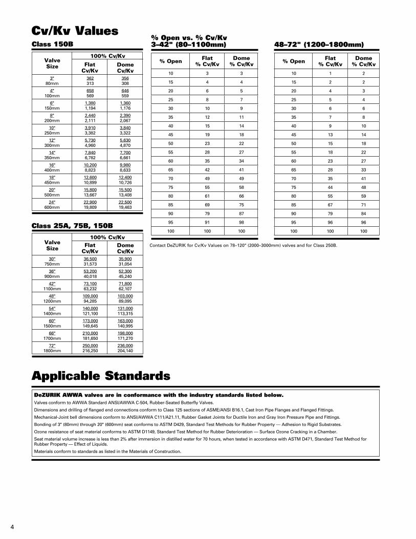
Contact DeZURIK for Cv/Kv Values on 78–120" (2000–3000mm) valves and for Class 250B.
Cv/Kv ValuesClass 150B
Valve Size Flat
Cv/KvDomeCv/Kv
3" 362 356 80mm 313 308
4" 658 646 100mm 569 559
6" 1,380 1,360 150mm 1,194 1,176
8" 2,440 2,390 200mm 2,111 2,067
10" 3,910 3,840 250mm 3,382 3,322
12" 5,730 5,630 300mm 4,960 4,870
14" 7,840 7,700 350mm 6,782 6,661
16" 10,200 9,980 400mm 8,823 8,633
18" 12,600 12,400 450mm 10,899 10,726
20" 15,800 15,500 500mm 13,667 13,408
24" 22,900 22,500 600mm 19,809 19,463
% Open vs. % Cv/Kv3–42" (80–1100mm)
% Open Flat % Cv/Kv
Dome% Cv/Kv
10 3 3
15 4 4
20 6 5
25 8 7
30 10 9
35 12 11
40 15 14
45 19 18
50 23 22
55 28 27
60 35 34
65 42 41
70 49 49
75 55 58
80 61 66
85 69 75
90 79 87
95 91 98
100 100 100
48–72" (1200–1800mm)
% Open Flat % Cv/Kv
Dome% Cv/Kv
10 1 2
15 2 2
20 4 3
25 5 4
30 6 6
35 7 8
40 9 10
45 13 14
50 15 18
55 18 22
60 23 27
65 28 33
70 35 41
75 44 48
80 55 59
85 67 71
90 79 84
95 96 96
100 100 100
DeZURIK AWWA valves are in conformance with the industry standards listed below.Valves conform to AWWA Standard ANSI/AWWA C-504, Rubber-Seated Butterfly Valves.
Dimensions and drilling of flanged end connections conform to Class 125 sections of ASME/ANSI B16.1, Cast Iron Pipe Flanges and Flanged Fittings.
Mechanical-Joint bell dimensions conform to ANSI/AWWA C111/A21.11, Rubber Gasket Joints for Ductile Iron and Gray Iron Pressure Pipe and Fittings.
Bonding of 3" (80mm) through 20" (600mm) seat conforms to ASTM D429, Standard Test Methods for Rubber Property — Adhesion to Rigid Substrates.
Ozone resistance of seat material conforms to ASTM D1149, Standard Test Method for Rubber Deterioration — Surface Ozone Cracking in a Chamber.
Seat material volume increase is less than 2% after immersion in distilled water for 70 hours, when tested in accordance with ASTM D471, Standard Test Method for Rubber Property — Effect of Liquids.
Materials conform to standards as listed in the Materials of Construction.
Applicable Standards
100% Cv/Kv
Class 25A, 75B, 150B
ValveSize Flat
Cv/KvDomeCv/Kv
30" 36,500 35,900 750mm 31,573 31,054
36" 53,200 52,300 900mm 40,018 45,240
42" 73,100 71,800 1100mm 63,232 62,107
48" 109,000 103,000 1200mm 94,285 89,095
54" 140,000 131,000 1400mm 121,100 113,315
60" 173,000 163,000 1500mm 149,645 140,995
66" 210,000 198,000 1700mm 181,650 171,270
72" 250,000 236,000 1800mm 216,250 204,140
100% Cv/Kv
5
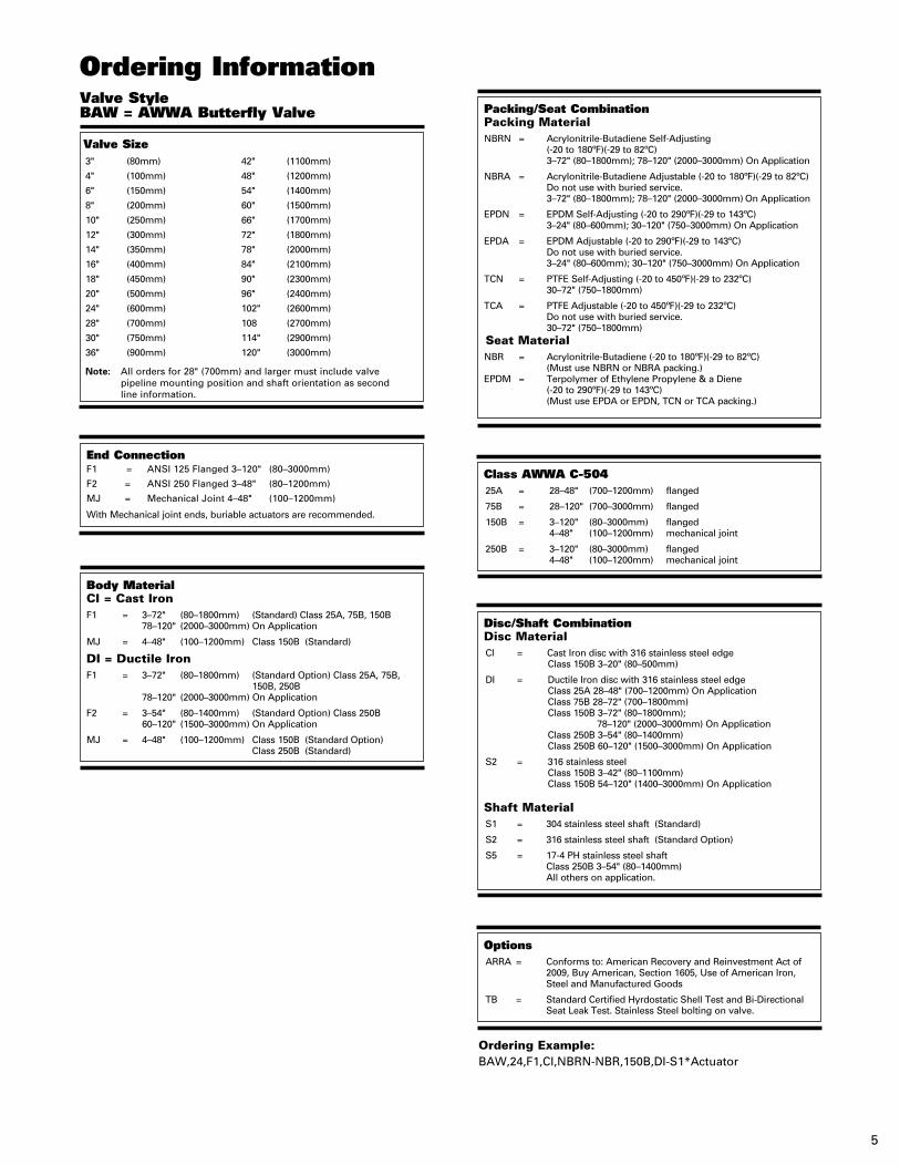
Ordering Information
Valve Size3" (80mm) 42" (1100mm)
4" (100mm) 48" (1200mm)
6" (150mm) 54" (1400mm)
8" (200mm) 60" (1500mm)
10" (250mm) 66" (1700mm)
12" (300mm) 72" (1800mm)
14" (350mm) 78" (2000mm)
16" (400mm) 84" (2100mm)
18" (450mm) 90" (2300mm)
20" (500mm) 96" (2400mm)
24" (600mm) 102" (2600mm)
28" (700mm) 108 (2700mm)
30" (750mm) 114" (2900mm)
36" (900mm) 120" (3000mm)
Note: All orders for 28" (700mm) and larger must include valve pipeline mounting position and shaft orientation as second line information.
End ConnectionF1 = ANSI 125 Flanged 3–120" (80–3000mm)
F2 = ANSI 250 Flanged 3–48" (80–1200mm)
MJ = Mechanical Joint 4–48" (100–1200mm)
With Mechanical joint ends, buriable actuators are recommended.
Class AWWA C-50425A = 28–48" (700–1200mm) flanged
75B = 28–120" (700–3000mm) flanged
150B = 3–120" (80–3000mm) flanged 4–48" (100–1200mm) mechanical joint
250B = 3–120" (80–3000mm) flanged 4–48" (100–1200mm) mechanical joint
OptionsARRA = Conforms to: American Recovery and Reinvestment Act of
2009, Buy American, Section 1605, Use of American Iron, Steel and Manufactured Goods
TB = Standard Certified Hyrdostatic Shell Test and Bi-Directional Seat Leak Test. Stainless Steel bolting on valve.
Body MaterialCI = Cast IronF1 = 3–72" (80–1800mm) (Standard) Class 25A, 75B, 150B 78–120" (2000–3000mm) On Application
MJ = 4–48" (100–1200mm) Class 150B (Standard)
DI = Ductile IronF1 = 3–72" (80–1800mm) (Standard Option) Class 25A, 75B, 150B, 250B 78–120" (2000–3000mm) On Application
F2 = 3–54" (80–1400mm) (Standard Option) Class 250B 60–120" (1500–3000mm) On Application
MJ = 4–48" (100–1200mm) Class 150B (Standard Option) Class 250B (Standard)
Packing/Seat CombinationPacking MaterialNBRN = Acrylonitrile-Butadiene Self-Adjusting (-20 to 180ºF)(-29 to 82ºC) 3–72" (80–1800mm); 78–120" (2000–3000mm) On Application
NBRA = Acrylonitrile-Butadiene Adjustable (-20 to 180ºF)(-29 to 82ºC) Do not use with buried service. 3–72" (80–1800mm); 78–120" (2000–3000mm) On Application
EPDN = EPDM Self-Adjusting (-20 to 290ºF)(-29 to 143ºC) 3–24" (80–600mm); 30–120" (750–3000mm) On Application
EPDA = EPDM Adjustable (-20 to 290ºF)(-29 to 143ºC) Do not use with buried service. 3–24" (80–600mm); 30–120" (750–3000mm) On Application
TCN = PTFE Self-Adjusting (-20 to 450ºF)(-29 to 232ºC) 30–72" (750–1800mm)
TCA = PTFE Adjustable (-20 to 450ºF)(-29 to 232ºC) Do not use with buried service. 30–72" (750–1800mm)Seat MaterialNBR = Acrylonitrile-Butadiene (-20 to 180ºF)(-29 to 82ºC) (Must use NBRN or NBRA packing.)EPDM = Terpolymer of Ethylene Propylene & a Diene (-20 to 290ºF)(-29 to 143ºC) (Must use EPDA or EPDN, TCN or TCA packing.)
Disc/Shaft CombinationDisc MaterialCI = Cast Iron disc with 316 stainless steel edge Class 150B 3–20" (80–500mm)
DI = Ductile Iron disc with 316 stainless steel edge Class 25A 28–48" (700–1200mm) On Application Class 75B 28–72" (700–1800mm) Class 150B 3–72" (80–1800mm); 78–120" (2000–3000mm) On Application Class 250B 3–54" (80–1400mm) Class 250B 60–120" (1500–3000mm) On Application
S2 = 316 stainless steel Class 150B 3–42" (80–1100mm) Class 150B 54–120" (1400–3000mm) On Application Shaft MaterialS1 = 304 stainless steel shaft (Standard)
S2 = 316 stainless steel shaft (Standard Option)
S5 = 17-4 PH stainless steel shaft Class 250B 3–54" (80–1400mm) All others on application.
Ordering Example:BAW,24,F1,CI,NBRN-NBR,150B,DI-S1*Actuator
Valve StyleBAW = AWWA Butterfly Valve
6
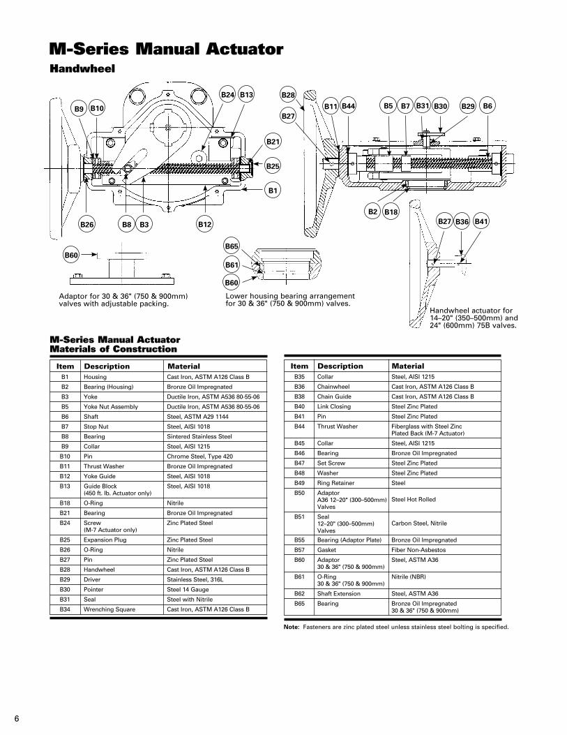
Note: Fasteners are zinc plated steel unless stainless steel bolting is specified.
Adaptor for 30 & 36" (750 & 900mm) valves with adjustable packing.
Lower housing bearing arrangement for 30 & 36" (750 & 900mm) valves.
Handwheel actuator for 14–20" (350–500mm) and 24" (600mm) 75B valves.
M-Series Manual ActuatorHandwheel
M-Series Manual ActuatorMaterials of Construction
B1 Housing Cast Iron, ASTM A126 Class B
B2 Bearing (Housing) Bronze Oil Impregnated
B3 Yoke Ductile Iron, ASTM A536 80-55-06
B5 Yoke Nut Assembly Ductile Iron, ASTM A536 80-55-06
B6 Shaft Steel, ASTM A29 1144
B7 Stop Nut Steel, AISI 1018
B8 Bearing Sintered Stainless Steel
B9 Collar Steel, AISI 1215
B10 Pin Chrome Steel, Type 420
B11 Thrust Washer Bronze Oil Impregnated
B12 Yoke Guide Steel, AISI 1018
B13 Guide Block Steel, AISI 1018 (450 ft. lb. Actuator only)
B18 O-Ring Nitrile
B21 Bearing Bronze Oil Impregnated
B24 Screw Zinc Plated Steel (M-7 Actuator only)
B25 Expansion Plug Zinc Plated Steel
B26 O-Ring Nitrile
B27 Pin Zinc Plated Steel
B28 Handwheel Cast Iron, ASTM A126 Class B
B29 Driver Stainless Steel, 316L
B30 Pointer Steel 14 Gauge
B31 Seal Steel with Nitrile
B34 Wrenching Square Cast Iron, ASTM A126 Class B
Item Description Material B35 Collar Steel, AISI 1215
B36 Chainwheel Cast Iron, ASTM A126 Class B
B38 Chain Guide Cast Iron, ASTM A126 Class B
B40 Link Closing Steel Zinc Plated
B41 Pin Steel Zinc Plated
B44 Thrust Washer Fiberglass with Steel Zinc Plated Back (M-7 Actuator)
B45 Collar Steel, AISI 1215
B46 Bearing Bronze Oil Impregnated
B47 Set Screw Steel Zinc Plated
B48 Washer Steel Zinc Plated
B49 Ring Retainer Steel
B50 Adaptor Steel Hot Rolled A36 12–20" (300–500mm)
Valves
B51 Seal Carbon Steel, Nitrile 12–20" (300–500mm)
Valves
B55 Bearing (Adaptor Plate) Bronze Oil Impregnated
B57 Gasket Fiber Non-Asbestos
B60 Adaptor Steel, ASTM A36 30 & 36" (750 & 900mm)
B61 O-Ring Nitrile (NBR) 30 & 36" (750 & 900mm)
B62 Shaft Extension Steel, ASTM A36
B65 Bearing Bronze Oil Impregnated 30 & 36" (750 & 900mm)
Item Description Material
B41B36B27B2
B6B29B30B31B7B5B44B11
B28B24 B13
B21
B25
B1
B12
B65
B61
B60
B3B8B26
B60
B9 B10B27
B18
7
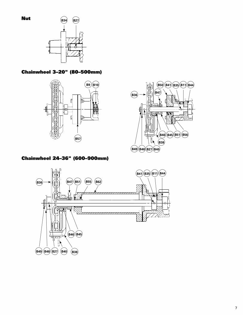
Nut
Chainwheel 3–20" (80–500mm)
Chainwheel 24–36" (600–900mm)
B27B34
B57
B10B9
B36B47
B50 B41 B35 B11 B44
B49
B44B11B35B41
B62B55B51B47B36
B49 B48 B27 B40 B38
B46 B45
B48 B27 B40
B38
B46 B45 B51 B56
8
Buried Actuator Cover
Handwheel
B35 B44 B34 B91 B33 B29 B28 B32
B27
B25
B45B13B24B1B14B13B16B40
B43
B15
B18
B17
B8 B47 B46
B34
B9B7B6B3B10
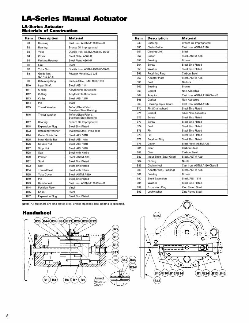
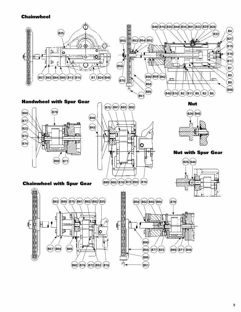
LA-Series ActuatorMaterials of Construction
B1 Housing Cast Iron, ASTM A126 Class B
B2 Bearing Bronze Oil Impregnated
B3 Yoke Ductile Iron, ASTM A536 80-55-06
B4 Cover Steel Plate, A36 HR
B5 Packing Retainer Steel Plate, A36 HR
B6 Link Steel
B7 Yoke Nut Ductile Iron, ASTM A536 80-55-06
B8 Guide Nut Powder Metal 8020 23B (LA-4 & LA-6)
B9 Retaining Ring Carbon Steel, SAE 1060-1090
B10 Input Shaft Steel, AISI 1141
B11 O-Ring Acrylonitrile-Butadiene
B12 O-Ring Acrylonitrile-Butadiene
B13 Collar Steel, AISI 1215
B14 Pin Steel
B15 Thrust Washer Teflon/Glass Fabric, Stainless Steel Backing
B16 Thrust Washer Teflon/Glass Fabric, Stainless Steel Backing
B17 Bearing Bronze Oil Impregnated
B18 Expansion Plug Steel Zinc Plated
B23 Retaining Washer Stainless Steel, Type 18-8
B24 Outer Guide Bar Steel, AISI 1018
B25 Inner Guide Bar Steel, AISI 1018
B26 Square Nut Steel, AISI 1018
B27 Stop Nut Steel, AISI 1018
B28 Seal Steel with Nitrile
B29 Pointer Steel, ASTM A36
B32 Stud Steel Zinc Plated
B33 Nut Steel Zinc Plated
B34 Thread Seal Steel with Nitrile
B35 Yoke Cover Steel, ASTM A569
B40 Pin Steel Zinc Plated
B43 Handwheel Cast Iron, ASTM A126 Class B
B44 Position Plate Vinyl
B45 Shim Steel
B47 Expansion Plug Steel Zinc Plated
Note: All fasteners are zinc plated steel unless stainless steel bolting is specified.
Item Description Material
LA-Series Manual Actuator
Item Description Material B48 Bushing Bronze Oil Impregnated
B50 Chain Guide Cast Iron, ASTM A126
B51 Closing Link Steel
B52 Collar Steel, ASTM A36
B53 Bearing Bronze
B54 Screw Steel Zinc Plated
B55 Washer Steel Zinc Plated
B56 Retaining Ring Carbon Steel
B57 Adaptor Plate Steel, ASTM A36
B58 Seal Garlock
B62 Bearing Bronze
B63 Gasket Non-Asbestos
B64 Adaptor Cast Iron, ASTM A126 Class B
B65 Gasket Non-Asbestos
B69 Housing (Spur Gear) Cast Iron, ASTM A126
B70 Pin (Chainwheel) Steel Zinc Plated
B71 Gasket Fiber Non-Asbestos
B72 Screw Steel Zinc Plated
B73 Screw Steel Zinc Plated
B74 Seal Steel Zinc Plated
B75 Pin Steel Zinc Plated
B76 Pin Steel Zinc Plated
B77 Retainer Ring Steel Zinc Plated
B78 Cover Steel Plate, ASTM A36
B81 Gear Carbon Steel
B82 Gear Carbon Steel
B83 Input Shaft (Spur Gear) Steel, ASTM A29
B84 O-Ring Nitrile
B85 Chainwheel Cast Iron, ASTM A126 Class B
B88 Adaptor (Adj. Packing) Steel, ASTM A36
B89 Bearing Bronze
B90 Shaft Extension Steel, AISI 1215
B91 Washer Steel Zinc Plated
B92 Expansion Plug Zinc Plated Steel
B93 Lockwasher Zinc Plated Steel
9
Handwheel with Spur Gear Nut
Nut with Spur Gear
Chainwheel with Spur Gear
Chainwheel
B63
B57 B64 B65
B82 B76 B72 B93 B16
B89 B75 B81 B83 B92 B25 B58
B40
B62B58B90
B50
B85B51
B10 B2 B11 B5 B3 B6
B7
B17
B18
B15
B27
B4B28
B45B24B1B14B13B65B64B63B57
B25
B26 B40
B40B26
B32
B29B33B91B34B44B35B16B48
B52B54B53B55
B56
B70
B9
B8
B88
B62 B40 B84 B78
B48B71B69B23B77
B51
B85
B50
B90
B78B84
B77
B23
B73
B74
B69 B71
B75
B40
B43
B89 B82 B76 B72 B93 B16
B81 B83 B92

10
Pneumatic/Low Pressure Oil HydraulicStandard and C-540
T-Series Cylinder Actuator
C10C9
C18 C17
C16
C11
C12
C19C13 C14 C8 C7 C6 C3 C1 C2 C4
B6 B7 B23
B3 B35 B24 B11 B19Construction as used with Water Hydraulic Cylinder
B55 B56
B50
B13 B25 B29 B30
B1 B5 B49
T-Series ActuatorMaterials of Construction
B1 Housing Cast Iron, ASTM A126 Class B
B3 Bearing Bronze
B5 Yoke Cast Ductile Iron, A536
B6 Yoke Nut Cold Rolled Steel
B7 Bearing Sintered Stainless Steel
B11 Stop Nut Cold Rolled Steel
B13 Guide Rail Cold Rolled Steel
B19 Gasket Neoprene
B23 Lower Yoke Guide (TW-7 only) Steel, AISI 1215
B24 Upper Yoke Guide (TW-7 only) Steel, ASTM A366
B25 Guide Rail (TW-7 only) Steel, ASTM A36
B29 Gasket Neoprene
B30 Cap Fiberglass
B35 Stay Pin Steel
B49 Screw Alloy Steel
B50 Key Steel, AISI 1018
B55 Adaptor (Hydraulic only) Cast Iron, ASTM A126 Class B
B56 Wiper (Hydraulic only) Carbon Steel
Note: All fasteners are zinc plated steel unless stainless steel bolting is specified.
Item Description Material
Pneumatic/Low Pressure Oil Hydraulic CylinderMaterials of Construction
C1 Cylinder Head Cast Iron, ASTM A126 Class B Ductile Iron, ASTM A536 65-45-12
C2 Bearing Bronze Oil Impregnated Bronze Oil Impregnated
C3 Rod Seal Teflon with NBR Teflon with NBR
C4 Piston Rod Steel, AISI 1215 Chrome Plated Steel, AISI 1215 Chrome Plated
C6 O-Ring Acrylonitrile-Butadiene Acrylonitrile-Butadiene
C7 Cylinder Tube Fiberglass Fiberglass
C8 Piston Cast Iron, ASTM A126 Class B Cast Iron, ASTM A126 Class B
C9 O-Ring Acrylonitrile-Butadiene Acrylonitrile-Butadiene
C10 Piston Seal Virgin Teflon Virgin Teflon
C11 Nut Zinc Plated Steel Zinc Plated Steel
C12 Cylinder Cap Ductile Iron, ASTM A536 65-45-12 Ductile Iron, ASTM A536 65-45-12
C13 Tie Rod Zinc Plated Steel Steel, AISI C1018 Zinc Plated
C14 Washer Zinc Plated Steel Zinc Plated Steel
C15 Nut Zinc Plated Steel Zinc Plated Steel
C16 Seal Thread Steel with Nitrile Steel with Nitrile
C17 Jam Nut Zinc Plated Steel Zinc Plated Steel
C18 Set Screw Zinc Plated Steel Zinc Plated Steel
C19 O-Ring Acrylonitrile-Butadiene Acrylonitrile-Butadiene
Item Description Standard Construction C-540 Construction
C15
11
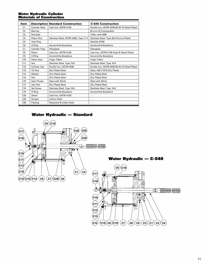
Water Hydraulic CylinderMaterials of Construction
C1 Cylinder Head Cast Iron, ASTM A126 Ductile Iron, ASTM A536 65-45-12 Nickel Plated
C2 Bearing – Bronze Oil Impregnated
C3 Rod Seal – Teflon with NBR
C4 Piston Rod Stainless Steel, ASTM A564, Type 17-4 Stainless Steel, Type 304 Chrome Plated
C5 Vent Plug – Alemite 47200
C6 O-Ring Acrylonitrile-Butadiene Acrylonitrile-Butadiene
C7 Cylinder Tube Fiberglass Fiberglass
C8 Piston Cast Iron, ASTM A126 Cast Iron, ASTM A126 Class B Nickel Plated
C9 O-Ring Acrylonitrile-Butadiene Acrylonitrile-Butadiene
C10 Piston Seal Virgin Teflon Virgin Teflon
C11 Nut Stainless Steel, Type 18-8 Stainless Steel, Type 18-8
C12 Cylinder Cap Ductile Iron, ASTM A536 Ductile Iron, ASTM A536 65-45-12 Nickel Plated
C13 Tie Rod Zinc Plated Steel Steel, AISI C1018 Zinc Plated
C14 Washer Zinc Plated Steel Zinc Plated Steel
C15 Nut Zinc Plated Steel Zinc Plated Steel
C16 Seal Thread Steel with Nitrile Steel with Nitrile
C17 Jam Nut Zinc Plated Steel Zinc Plated Steel
C18 Set Screw Stainless Steel, Type 18-8 Stainless Steel, Type 18-8
C19 O-Ring Acrylonitrile-Butadiene Acrylonitrile-Butadiene
C25 Gland Cast Iron, ASTM A126 –
C29 Scraper Carbon Steel –
C30 Packing Neoprene & Cotton Duck –
Item Description Standard Construction C-540 Construction
Water Hydraulic — Standard
C9 C10
C30 C25
C29
C4C1
C6C29C7
C18
C17
C16
C11
C12
C19
C13 C14 C8C15
Water Hydraulic — C-540
C9 C10
C5C6C7 C2 C4C1C3
C18
C17
C16
C11
C12
C19
C13
C14 C8C15
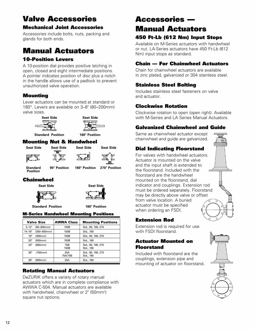
Valve AccessoriesMechanical Joint AccessoriesAccessories include bolts, nuts, packing and glands for both ends.
Manual Actuators10-Position LeversA 10-position dial provides positive latching in open, closed and eight intermediate positions. A pointer indicates position of disc plus a notch in the handle allows use of a padlock to prevent unauthorized valve operation.
MountingLever actuators can be mounted at standard or 180°. Levers are available on 3–8" (80–200mm) valve sizes. Seat Side Seat Side
Standard Position 180° Position
12
ChainwheelSeat Side Seat Side
Standard Position 180° Position
Seat Side Seat Side Seat Side Seat Side
Standard Position
90° Position 180° Position 270° Position
Accessories —Manual Actuators450 Ft-Lb (612 Nm) Input StopsAvailable on M-Series actuators with handwheel or nut. LA-Series actuators have 450 Ft-Lb (612 Nm) input stops as standard.
Chain — For Chainwheel ActuatorsChain for chainwheel actuators are available in zinc plated, galvanized or 304 stainless steel.
Stainless Steel Bolting Includes stainless steel fasteners on valve and actuator.
Clockwise RotationClockwise rotation to open (open right). Available with M-Series and LA Series Manual Actuators.
Galvanized Chainwheel and GuideSame as chainwheel actuator except chainwheel and guide are galvanized.
Dial Indicating FloorstandFor valves with handwheel actuators. Actuator is mounted on the valve and the input shaft is extended to the floorstand. Included with the floorstand are the handwheel mounted on the floorstand, dial indicator and couplings. Extension rod must be ordered separately. Floorstand may be directly above valve or offset from valve location. A buried actuator must be specified when ordering an FSDI.
Extension RodExtension rod is required for use with FSDI floorstand.
Actuator Mounted on FloorstandIncluded with floorstand are the couplings, extension pipe and mounting of actuator on floorstand.
M-Series Handwheel Mounting Positions
3–12" (80–300mm) 150B Std., 90, 180, 270
14–16" (350–400mm) 150B Std., 180
18" (450mm) 150B Std., 90, 180, 270
20" (500mm) 150B Std., 180
24" (600mm) 75B Std., 90, 180, 270 150B Std., 180
30" (750mm) 25A Std., 90, 180, 270 75A/75B Std., 180
36" (900mm) 25A Std., 180
Valve Size AWWA Class Mounting Positions
Mounting Nut & Handwheel
Rotating Manual ActuatorsDeZURIK offers a variety of rotary manual actuators which are in complete compliance with AWWA C-504. Manual actuators are available with handwheel, chainwheel or 2" (50mm2) square nut options.
13
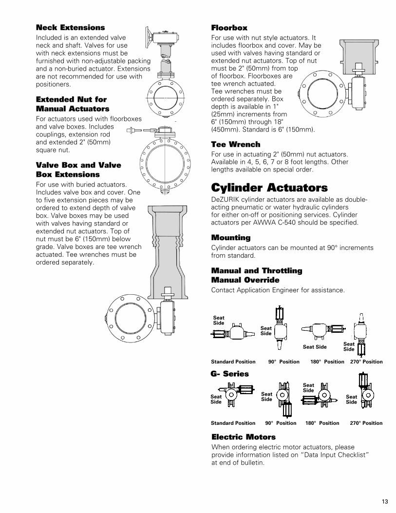
Neck ExtensionsIncluded is an extended valve neck and shaft. Valves for use with neck extensions must be furnished with non-adjust able packing and a non-buried actuator. Extensions are not recommended for use with positioners.
Extended Nut for Manual Actuators For actuators used with floorboxes and valve boxes. Includes couplings, extension rod and extended 2" (50mm) square nut.
Valve Box and Valve Box ExtensionsFor use with buried actuators. Includes valve box and cover. One to five extension pieces may be ordered to extend depth of valve box. Valve boxes may be used with valves having standard or extended nut actuators. Top of nut must be 6" (150mm) below grade. Valve boxes are tee wrench actuated. Tee wrenches must be ordered separately.
FloorboxFor use with nut style actuators. It includes floorbox and cover. May be used with valves having standard or extended nut actuators. Top of nut must be 2" (50mm) from top of floorbox. Floorboxes are tee wrench actuated. Tee wrenches must be ordered separately. Box depth is available in 1" (25mm) increments from 6" (150mm) through 18" (450mm). Standard is 6" (150mm).
Tee WrenchFor use in actuating 2" (50mm) nut actuators. Available in 4, 5, 6, 7 or 8 foot lengths. Other lengths available on special order.
Cylinder ActuatorsDeZURIK cylinder actuators are available as double-acting pneumatic or water hydraulic cylinders for either on-off or positioning services. Cylinder actuators per AWWA C-540 should be specified.
MountingCylinder actuators can be mounted at 90° increments from standard.
Manual and Throttling Manual OverrideContact Application Engineer for assistance.
T- Series
G- SeriesSeat Side
Seat SideSeat
SideSeat Side
Seat Side Seat Side
Seat Side
Seat Side
Electric MotorsWhen ordering electric motor actuators, please provide information listed on “Data Input Checklist” at end of bulletin.
Standard Position 90° Position 180° Position 270° Position
Standard Position 90° Position 180° Position 270° Position
14
Accessories — Cylinder ActuatorsPositionersDeZURIK offers both pneumatic and electronic signal valve positioners for use with cylinder actuators.
GaugesPneumatic positioners are available with three gauges mounted and piped; electronic positioners are available with two gauges mounted and piped.
4-Way Solenoid ValvesFor cylinder actuators, 4-way direct acting, two position solenoid valves feature metal enclosures, .25" (6mm) NPT connections, Cv of .70 and a maximum pressure differential of 125 psi (8.5 Bar). Solenoid coil voltage is both 110/50/1 and 120/60/1 AC power. Contact Sartell Valves, Inc. for DC voltage. Solenoids are available with or without manual overrides. On large valves, furnish valve/actuator size, service conditions, and required operating speed for recommendations. Solenoid action should be specified.
Air Filter RegulatorFor use on all pneumatic actuators. Includes a pressure reducing valve with filter and gauge. Maximum supply is 100 psi (7 Bar).
Speed Control ValvesSpeed control valves are available for controlling opening and closing speed on cylinder actuators.
Position Indicating SwitchesAvailable in NEMA 4, 4x, 7 or 9 ratings. Switches are available as two SPDT or four SPDT.
Neck ExtensionFor 3–20" (80–500mm) valves using T-Series Cylinder actuators. Included is the extended valve neck and shaft with actuator mounted.
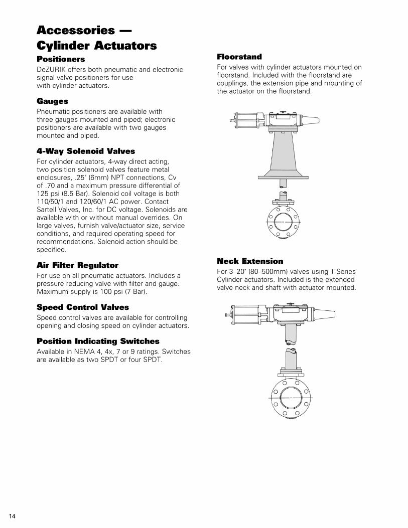
FloorstandFor valves with cylinder actuators mounted on floorstand. Included with the floorstand are couplings, the extension pipe and mounting of the actuator on the floorstand.
15
Dimensions
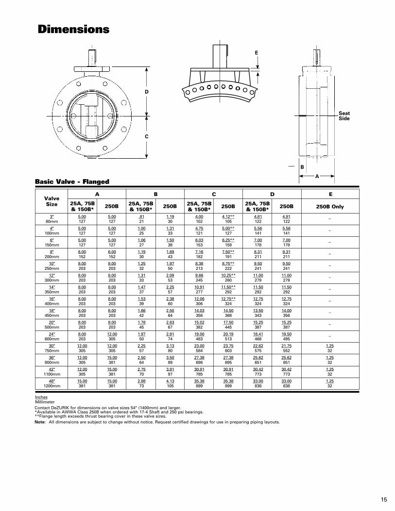
Basic Valve - Flanged
3" 5.00 5.00 .81 1.19 4.00 4.12** 4.81 4.81 – 80mm 127 127 21 30 102 105 122 122
4" 5.00 5.00 1.00 1.31 4.75 5.00** 5.56 5.56 – 100mm 127 127 25 33 121 127 141 141
6" 5.00 5.00 1.06 1.50 6.03 6.25** 7.00 7.00 – 150mm 127 127 27 38 153 159 178 178
8" 6.00 6.00 1.19 1.69 7.16 7.50** 8.31 8.31 – 200mm 152 152 30 43 182 191 211 211
10" 8.00 8.00 1.25 1.97 8.38 8.75** 9.50 9.50 – 250mm 203 203 32 50 213 222 241 241
12" 8.00 8.00 1.31 2.09 9.66 10.25** 11.00 11.00 – 300mm 203 203 33 53 245 260 279 279
14" 8.00 8.00 1.47 2.25 10.91 11.50** 11.50 11.50 – 350mm 203 203 37 57 277 292 292 292
16" 8.00 8.00 1.53 2.38 12.06 12.75** 12.75 12.75 – 400mm 203 203 39 60 306 324 324 324
18" 8.00 8.00 1.66 2.50 14.03 14.50 13.50 14.00 – 450mm 203 203 42 64 356 368 343 356
20" 8.00 8.00 1.78 2.63 15.02 17.50 15.25 15.25 – 500mm 203 203 45 67 382 445 387 387
24" 8.00 12.00 1.97 2.91 19.00 20.19 18.41 19.50 – 600mm 203 305 50 74 483 513 468 495
30" 12.00 12.00 2.25 3.13 23.00 23.75 22.62 21.75 1.25 750mm 305 305 57 80 584 603 575 552 32
36" 12.00 15.00 2.50 3.50 27.38 27.38 25.62 25.62 1.25 900mm 305 381 64 89 696 695 651 651 32
42" 12.00 15.00 2.75 3.81 30.91 30.91 30.42 30.42 1.25 1100mm 305 381 70 97 785 785 773 773 32
48" 15.00 15.00 2.88 4.13 35.38 35.38 33.00 33.00 1.25 1200mm 381 381 73 105 899 899 838 838 32
ValveSize
D ECBA
25A, 75B & 150B*
25A, 75B & 150B*
25A, 75B & 150B*
25A, 75B & 150B*
250B 250B 250B 250B 250B Only
InchesMillimeterContact DeZURIK for dimensions on valve sizes 54" (1400mm) and larger.*Available in AWWA Class 250B when ordered with 17-4 Shaft and 250 psi bearings.**Flange length exceeds thrust bearing cover in these valve sizes.Note: All dimensions are subject to change without notice. Request certified drawings for use in preparing piping layouts.
D
E
B
Seat Side
A
C
16
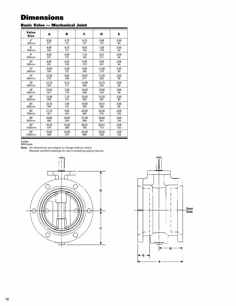
Dimensions
InchesMillimeterNote: All dimensions are subject to change without notice. Request certified drawings for use in preparing piping layouts.
Basic Valve — Mechanical Joint
4" 8.56 4.75 4.75 5.56 2.50 100mm 217 121 121 141 64
6" 8.88 4.75 6.03 7.00 2.50 150mm 226 121 153 178 64
8" 9.50 5.00 7.16 8.31 2.50 200mm 241 127 182 211 64
10" 9.88 5.25 8.38 9.50 2.50 250mm 251 133 213 241 64
12" 10.00 5.38 9.66 11.00 2.50 300mm 254 137 245 279 64
14" 12.38 6.62 10.91 11.50 3.50 350mm 315 168 277 292 89
16" 12.75 6.75 12.06 12.75 3.50 400mm 324 171 306 324 89
18" 13.42 7.00 14.03 13.50 3.50 450mm 341 178 356 343 89
20" 13.38 7.12 15.02 15.25 3.50 500mm 340 181 382 387 89
24" 13.75 7.50 19.00 18.41 3.50 600mm 349 191 483 468 89
30" 17.75 9.62 23.00 22.62 4.00 750mm 451 244 584 575 102
36" 18.00 10.00 27.38 25.62 4.00 900mm 458 254 696 651 102
42" 18.75 10.25 30.91 30.41 4.00 1100mm 476 260 785 772 102
48" 19.62 10.62 35.38 33.00 4.00 1200mm 498 270 898 838 102
ValveSize A C EB D
D
C
Seat Side
B
E
A
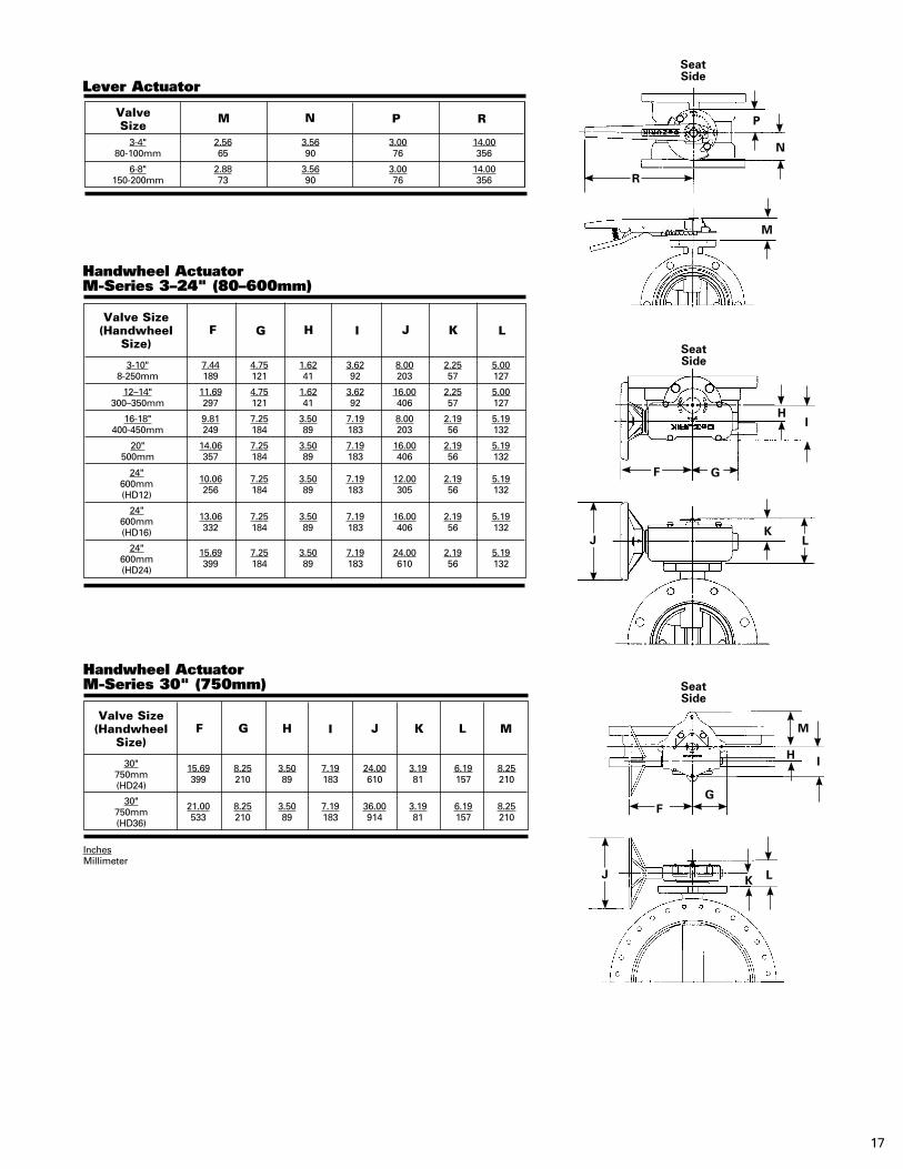
3-4" 2.56 3.56 3.00 14.00 80-100mm 65 90 76 356
6-8" 2.88 3.56 3.00 14.00 150-200mm 73 90 76 356
17
InchesMillimeter
P
N
M
Seat Side
Lever Actuator
ValveSize
M PN R
M
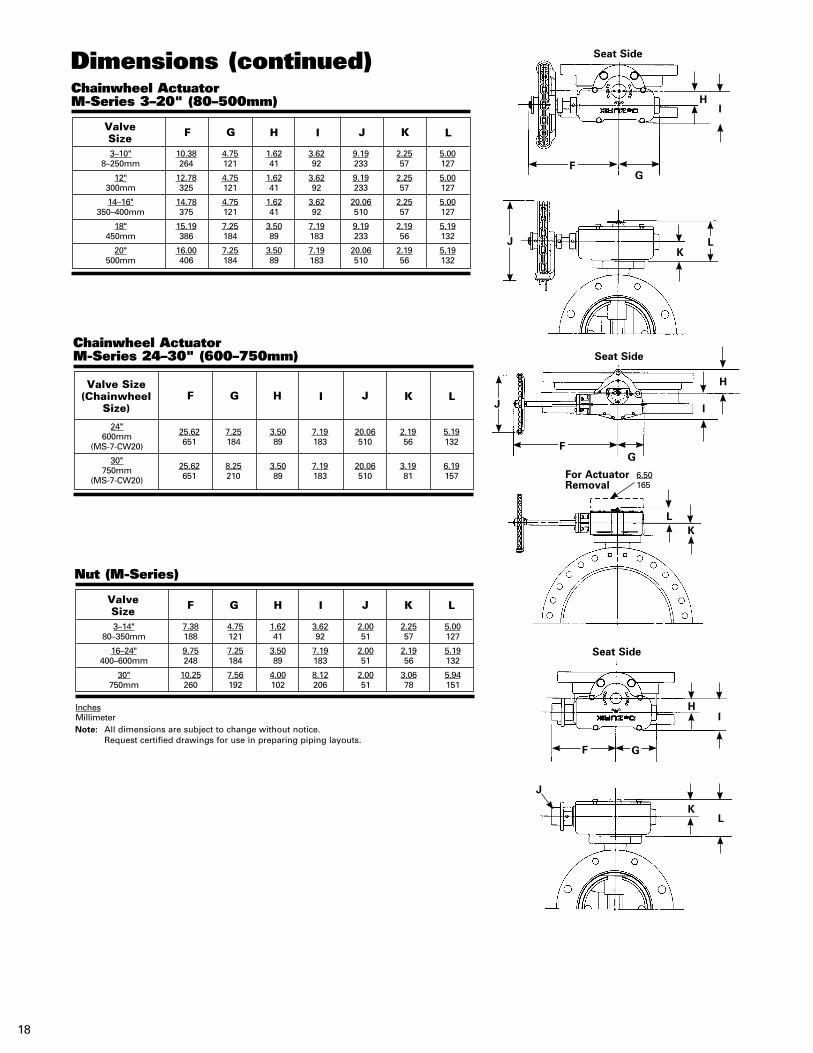
Handwheel ActuatorM-Series 30" (750mm)
15.69 8.25 3.50 7.19 24.00 3.19 6.19 8.25 399 210 89 183 610 81 157 210
21.00 8.25 3.50 7.19 36.00 3.19 6.19 8.25 533 210 89 183 914 81 157 210
Valve Size(Handwheel
Size)K LF H JG I
30"750mm(HD24)
30"750mm(HD36)
Handwheel ActuatorM-Series 3–24" (80–600mm)
3-10" 7.44 4.75 1.62 3.62 8.00 2.25 5.00 8-250mm 189 121 41 92 203 57 127
12–14" 11.69 4.75 1.62 3.62 16.00 2.25 5.00 300–350mm 297 121 41 92 406 57 127
16-18" 9.81 7.25 3.50 7.19 8.00 2.19 5.19 400-450mm 249 184 89 183 203 56 132
20" 14.06 7.25 3.50 7.19 16.00 2.19 5.19 500mm 357 184 89 183 406 56 132
10.06 7.25 3.50 7.19 12.00 2.19 5.19 256 184 89 183 305 56 132
13.06 7.25 3.50 7.19 16.00 2.19 5.19 332 184 89 183 406 56 132
15.69 7.25 3.50 7.19 24.00 2.19 5.19 399 184 89 183 610 56 132
Valve Size(Handwheel
Size)K LF H JG I
24"600mm(HD12)
24"600mm(HD16)
24"600mm(HD24)
R
HI
K
Seat Side
J
K L
G
H I
M
Seat Side
L
GF
F
J
For Actuator Removal
6.50165
I
H
KL
Seat SideChainwheel ActuatorM-Series 24–30" (600–750mm)
25.62 7.25 3.50 7.19 20.06 2.19 5.19 651 184 89 183 510 56 132
25.62 8.25 3.50 7.19 20.06 3.19 6.19 651 210 89 183 510 81 157
Valve Size(Chainwheel
Size)K LF H JG I
24"600mm
(MS-7-CW20)
30"750mm
(MS-7-CW20)
Chainwheel ActuatorM-Series 3–20" (80–500mm)
3–10" 10.38 4.75 1.62 3.62 9.19 2.25 5.00 8–250mm 264 121 41 92 233 57 127
12" 12.78 4.75 1.62 3.62 9.19 2.25 5.00 300mm 325 121 41 92 233 57 127
14–16" 14.78 4.75 1.62 3.62 20.06 2.25 5.00 350–400mm 375 121 41 92 510 57 127
18" 15.19 7.25 3.50 7.19 9.19 2.19 5.19 450mm 386 184 89 183 233 56 132
20" 16.00 7.25 3.50 7.19 20.06 2.19 5.19 500mm 406 184 89 183 510 56 132
Valve Size K LF H JG I
Nut (M-Series)
3–14" 7.38 4.75 1.62 3.62 2.00 2.25 5.00 80–350mm 188 121 41 92 51 57 127
16–24" 9.75 7.25 3.50 7.19 2.00 2.19 5.19 400–600mm 248 184 89 183 51 56 132
30" 10.25 7.56 4.00 8.12 2.00 3.06 5.94 750mm 260 192 102 206 51 78 151
Valve Size K LF H JG I
InchesMillimeterNote: All dimensions are subject to change without notice. Request certified drawings for use in preparing piping layouts.
Dimensions (continued)
K
HI
G
Seat Side
L
HI
LK
J
Seat Side
18
J
GF
J
F
F G
LPneumatic
K
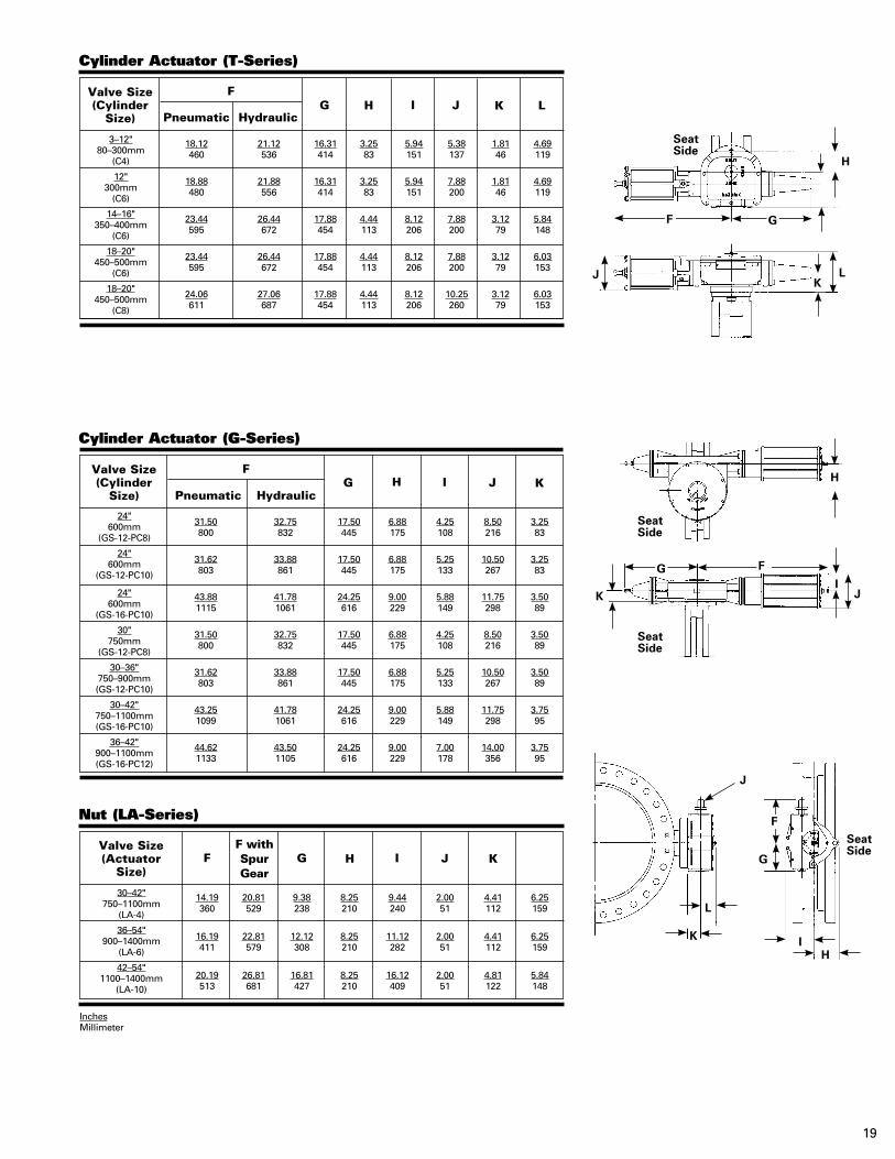
Cylinder Actuator (T-Series)
18.12 21.12 16.31 3.25 5.94 5.38 1.81 4.69 460 536 414 83 151 137 46 119
18.88 21.88 16.31 3.25 5.94 7.88 1.81 4.69 480 556 414 83 151 200 46 119
23.44 26.44 17.88 4.44 8.12 7.88 3.12 5.84 595 672 454 113 206 200 79 148
23.44 26.44 17.88 4.44 8.12 7.88 3.12 6.03 595 672 454 113 206 200 79 153
24.06 27.06 17.88 4.44 8.12 10.25 3.12 6.03 611 687 454 113 206 260 79 153
Valve Size(Cylinder
Size)I J
FH
HydraulicG
3–12"80–300mm
(C4)
12"300mm
(C6)
14–16"350–400mm
(C6)
18–20"450–500mm
(C6)
18–20"450–500mm
(C8)
PneumaticK
Cylinder Actuator (G-Series)
31.50 32.75 17.50 6.88 4.25 8.50 3.25 800 832 445 175 108 216 83
31.62 33.88 17.50 6.88 5.25 10.50 3.25 803 861 445 175 133 267 83
43.88 41.78 24.25 9.00 5.88 11.75 3.50 1115 1061 616 229 149 298 89
31.50 32.75 17.50 6.88 4.25 8.50 3.50 800 832 445 175 108 216 89
31.62 33.88 17.50 6.88 5.25 10.50 3.50 803 861 445 175 133 267 89
43.25 41.78 24.25 9.00 5.88 11.75 3.75 1099 1061 616 229 149 298 95
44.62 43.50 24.25 9.00 7.00 14.00 3.75 1133 1105 616 229 178 356 95
Valve Size(Cylinder
Size)I J
FH
HydraulicG
24"600mm
(GS-12-PC8)
24"600mm
(GS-12-PC10)
24"600mm
(GS-16-PC10)
30"750mm
(GS-12-PC8)
30–36"750–900mm(GS-12-PC10)
30–42"750–1100mm(GS-16-PC10)
36–42"900–1100mm(GS-16-PC12)
L
Nut (LA-Series)
14.19 20.81 9.38 8.25 9.44 2.00 4.41 6.25 360 529 238 210 240 51 112 159
16.19 22.81 12.12 8.25 11.12 2.00 4.41 6.25 411 579 308 210 282 51 112 159
20.19 26.81 16.81 8.25 16.12 2.00 4.81 5.84 513 681 427 210 409 51 122 148
Valve Size(Actuator
Size)J KF G I
F with Spur Gear
H
30–42"750–1100mm
(LA-4)
36–54"900–1400mm
(LA-6)
42–54"1100–1400mm
(LA-10)
Seat Side
I
H
JK
Seat Side
L
Seat Side
Seat Side
K
H
IG F
J
Seat Side
J
G
IH
K
L
InchesMillimeter
19
F G
F
Seat Side
K
G
L
I
H
F
20
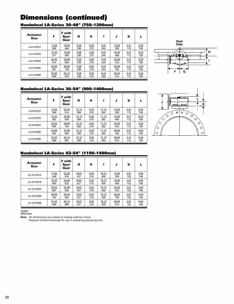
L
Handwheel LA-Series 30–48" (750–1200mm)
LA-4-HD12
11.62 18.25 9.38 8.25 9.44 12.00 4.41 6.25 295 464 238 210 240 305 112 159
LA-4-HD16
12.25 18.88 9.38 8.25 9.44 16.00 4.41 6.25 311 480 238 210 240 406 112 159
LA-4-HD24
20.25 26.88 9.38 8.25 9.44 24.00 4.41 6.25 514 683 238 210 240 610 112 159
LA-4-HD30
22.88 29.50 9.38 8.25 9.44 30.00 4.41 6.25 581 749 238 210 240 762 112 159
LA-4-HD36
25.50 32.12 9.38 8.25 9.44 36.00 4.41 6.25 648 816 238 210 240 914 112 159
Actuator Size J KF G I
F with Spur Gear
H
L
Handwheel LA-Series 36–54" (900–1400mm)
LA-6-HD12
13.62 20.25 12.12 8.25 11.12 12.00 4.41 6.25 346 514 308 210 282 305 112 159
LA-6-HD16
14.25 20.88 12.12 8.25 11.12 16.00 4.41 6.25 362 530 308 210 282 406 112 159
LA-6-HD24
22.25 28.88 12.12 8.25 11.12 24.00 4.41 6.25 565 734 308 210 282 610 112 159
LA-6-HD30
24.88 31.50 12.12 8.25 11.12 30.00 4.41 6.25 632 800 308 210 282 762 112 159
LA-6-HD36
27.50 34.12 12.12 8.25 11.12 36.00 4.41 6.25 699 867 308 210 282 914 112 159
Actuator Size J KF G I
F with Spur Gear
H
L
Handwheel LA-Series 42–54" (1100–1400mm)
LA-10-HD12
17.62 24.25 16.81 8.25 16.12 12.00 4.81 5.84 448 616 427 210 409 305 122 148
LA-10-HD16
18.25 24.88 16.81 8.25 16.12 16.00 4.81 5.84 464 632 427 210 409 406 122 148
LA-10-HD24
26.25 32.88 16.81 8.25 16.12 24.00 4.81 5.84 667 835 427 210 409 610 122 148
LA-10-HD30
28.88 35.50 16.81 8.25 16.12 30.00 4.81 5.84 734 902 427 210 409 762 122 148
LA-10-HD36
31.50 38.12 16.81 8.25 16.12 36.00 4.81 5.84 800 968 427 210 409 914 122 148
Actuator Size J KF G I
F with Spur Gear
H
InchesMillimeterNote: All dimensions are subject to change without notice. Request certified drawings for use in preparing piping layouts.
Dimensions (continued)
J
M
G
H I
Seat Side
J K
21
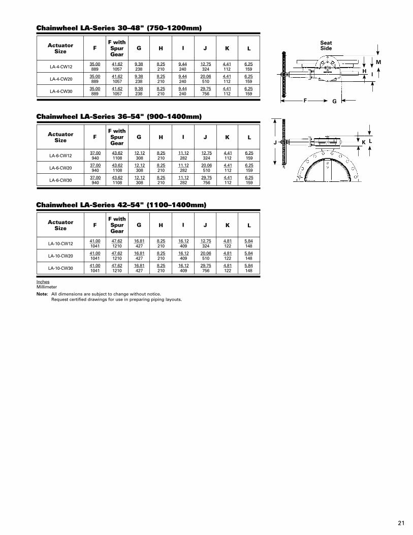
L
Chainwheel LA-Series 30–48" (750–1200mm)
LA-4-CW12
35.00 41.62 9.38 8.25 9.44 12.75 4.41 6.25 889 1057 238 210 240 324 112 159
LA-4-CW20
35.00 41.62 9.38 8.25 9.44 20.06 4.41 6.25 889 1057 238 210 240 510 112 159
LA-4-CW30
35.00 41.62 9.38 8.25 9.44 29.75 4.41 6.25 889 1057 238 210 240 756 112 159
Actuator Size J KF G I
F with Spur Gear
H
L
Chainwheel LA-Series 36–54" (900–1400mm)
LA-6-CW12
37.00 43.62 12.12 8.25 11.12 12.75 4.41 6.25 940 1108 308 210 282 324 112 159
LA-6-CW20
37.00 43.62 12.12 8.25 11.12 20.06 4.41 6.25 940 1108 308 210 282 510 112 159
LA-6-CW30
37.00 43.62 12.12 8.25 11.12 29.75 4.41 6.25 940 1108 308 210 282 756 112 159
Actuator Size J KF G I
F with Spur Gear
H
L
Chainwheel LA-Series 42–54" (1100–1400mm)
LA-10-CW12
41.00 47.62 16.81 8.25 16.12 12.75 4.81 5.84 1041 1210 427 210 409 324 122 148
LA-10-CW20
41.00 47.62 16.81 8.25 16.12 20.06 4.81 5.84 1041 1210 427 210 409 510 122 148
LA-10-CW30
41.00 47.62 16.81 8.25 16.12 29.75 4.81 5.84 1041 1210 427 210 409 756 122 148
Actuator Size J KF G I
F with Spur Gear
H
InchesMillimeter
Note: All dimensions are subject to change without notice. Request certified drawings for use in preparing piping layouts.
L
F
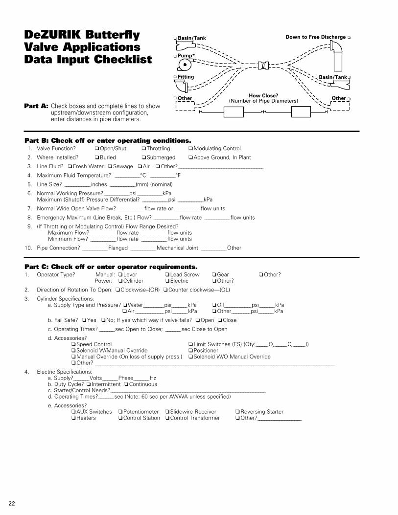
Part A: Check boxes and complete lines to show upstream/downstream configuration, enter distances in pipe diameters.
Part B: Check off or enter operating conditions. 1. Valve Function? o Open/Shut o Throttling o Modulating Control
2. Where Installed? o Buried o Submerged o Above Ground, In Plant
3. Line Fluid? o Fresh Water o Sewage o Air o Other?___________________________________________________
4. Maximum Fluid Temperature? _______________°C _______________°F
5. Line Size? _______________inches _______________(mm) (nominal)
6. Normal Working Pressure? _______________psi _______________kPa Maximum (Shutoff) Pressure Differential? _______________psi _______________kPa
7. Normal Wide Open Valve Flow? _______________flow rate or _______________flow units
8. Emergency Maximum (Line Break, Etc.) Flow? _______________flow rate _______________flow units
9. (If Throttling or Modulating Control) Flow Range Desired? Maximum Flow? _______________flow rate _______________flow units Minimum Flow? _______________flow rate _______________flow units
10. Pipe Connection? _______________Flanged _______________Mechanical Joint _______________Other
Part C: Check off or enter operator requirements.1. Operator Type? Manual: o Lever o Lead Screw o Gear o Other? Power: o Cylinder o Electric o Other?
2. Direction of Rotation To Open: o Clockwise–(OR) o Counter clockwise—(OL)
3. Cylinder Specifications: a. Supply Type and Pressure? o Water____________psi_________kPa o Oil________________psi_________kPa o Air _________________psi_________kPa o Other___________psi_________kPa
b. Fail Safe? o Yes o No; If yes which way if valve fails? o Open o Close
c. Operating Times? _________sec Open to Close; _________sec Close to Open
d. Accessories? o Speed Control o Limit Switches (ES) (Qty:_______O,_______C,_______I) o Solenoid W/Manual Override o Positioner o Manual Override (On loss of supply press.) o Solenoid W/O Manual Override o Other? ________________________________________________________________________________________________________________________________________________
4. Electric Specifications: a. Supply?_________Volts_________Phase_________Hz b. Duty Cycle? o Intermittent o Continuous c. Starter/Control Needs?_____________________________________________________________________________________________ d. Operating Times?_________sec (Note: 60 sec per AWWA unless specified)
e. Accessories? o AUX Switches o Potentiometer o Slidewire Receiver o Reversing Starter o Heaters o Control Station o Control Transformer o Other?__________________________
*Attach pump curve to checklist if available.
DeZURIK Butterfly Valve Applications Data Input Checklist
Basin/Tank
Basin/Tank
Down to Free Discharge
How Close? (Number of Pipe Diameters)
Pump*
Fitting
Other Other
22


DeZURIK reserves the right to incorporate our latest design and material changes without notice or obligation. Design features, materials of construction and dimensional data, as described in this bulletin, are provided for your information only
and should not be relied upon unless confirmed in writing by DeZURIK. Certified drawings are available upon request.
Printed in the U.S.A.
250 Riverside Ave. N. Sartell, Minnesota 56377 • Phone: 320-259-2000 • Fax: 320-259-2227
For information about our worldwide locations, approvals, certifications and local representative:Web Site: www.dezurik.com E-Mail: [email protected]
Sales and Service