20m g4bud mobile whip – iss 1.3 - rsars · pdf file20.01.2013 · notes 1....
TRANSCRIPT

This particular antenna was built specifically to take on holiday to Fuerteventura in the Canary
Islands, after it was originally tested from an inland site in the UK. Amongst my first contacts using
the FT817 and 5 watts was W8FHF in Ohio, who gave me a report of 5/6 on SSB.
The antenna was designed with the following in mind:
1. Quick and easy to set up and use
2. Light for air transport / breaks down to approx 50cm to fit in normal luggage
3. Must plug directly into the FT817 with no requirement for an ATU
4. Hatchback mounting, as magnetic materials are not allowed on aircraft
The antenna is very lightweight and as such is not really mechanically strong enough for true mobile
work, but is ideal for static mobile operation. Apart from the telescopic top section, it was built
entirely from “Junk box” items, in the true Ham Radio tradition. I am sure that anyone with access to
an engineering facility could make a much better job of it. If you want to see this antenna in action
with my FT817, go to the following link:
http://www.youtube.com/watch?v=Yenqmhy1lKM
1 Graphics by G8ODE Version iss 1.3 4/10/10
20m G4BUD Mobile Whip
Reproduced by permission of Barry G4BUD
2
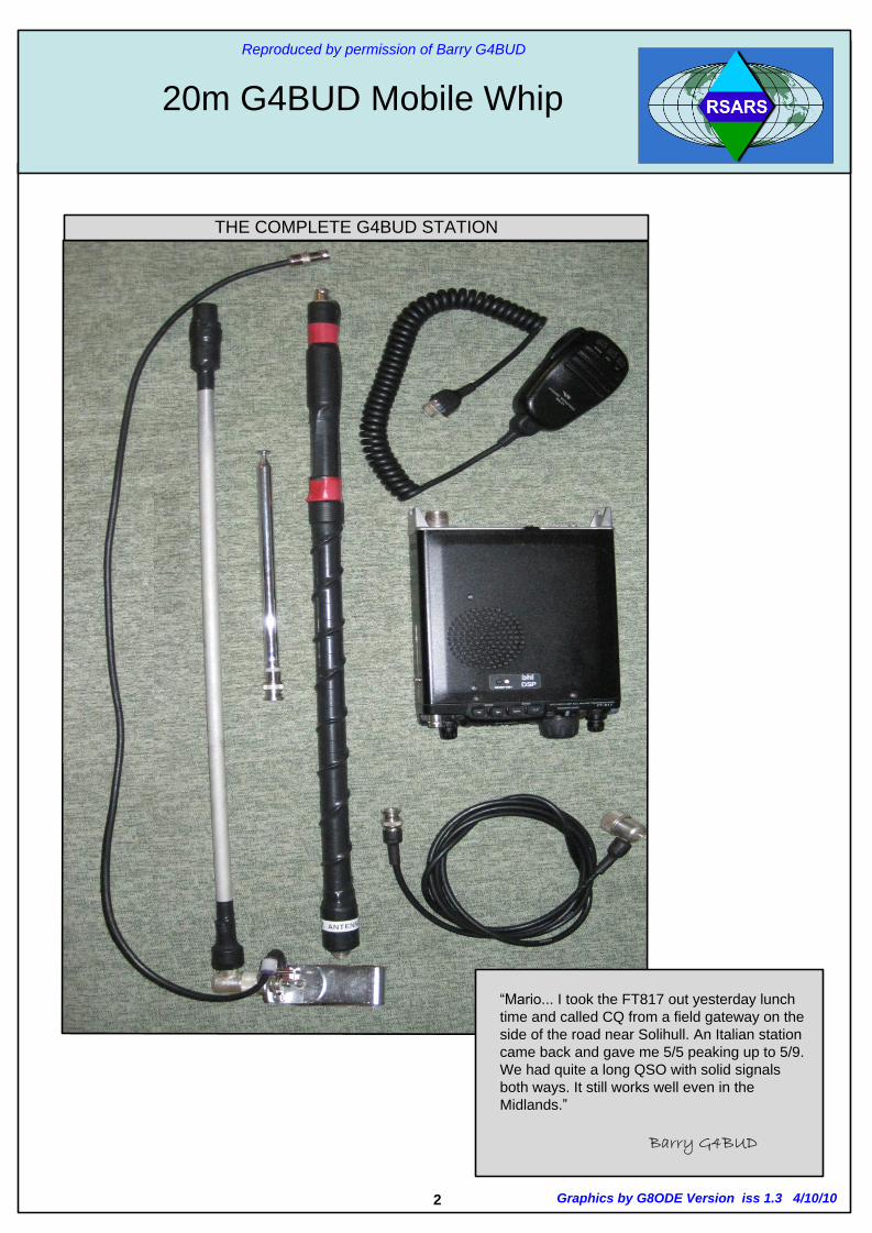
“Mario... I took the FT817 out yesterday lunch
time and called CQ from a field gateway on the
side of the road near Solihull. An Italian station
came back and gave me 5/5 peaking up to 5/9.
We had quite a long QSO with solid signals
both ways. It still works well even in the
Midlands.”
Barry G4BUD
THE COMPLETE G4BUD STATION
Graphics by G8ODE Version iss 1.3 4/10/10
20m G4BUD Mobile Whip
Reproduced by permission of Barry G4BUD
3
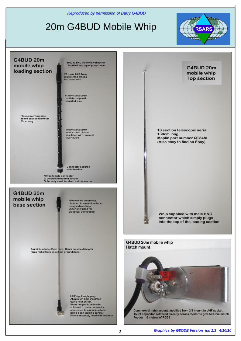
BNC to BNC bulkhead connector
Araldited into top of plastic tube
Graphics by G8ODE Version iss 1.3 4/10/10
20m G4BUD Mobile Whip
Reproduced by permission of Barry G4BUD

NOTES
1. Wire used for the coil is 24/0.2 multi-strand
plastic insulated wire hook up wire
2. The BNC and N-type connectors are secured
using epoxy resin adhesive.
3. The bottom of the coil is secured only to the
outer of the connector.
4. White PVC overflow pipe 18mmOD is used as
the coil fiormer.
5. Heat shrink PVC tube is used to cover the
joints.
30cm
8 turns spaced
over 30cm
11 turns close
wound
BNC-BNC
Bulkhead
Connector
N-Type Female
Connector
53 c
m
3.5c
m
2cm
16.5
cm
29 turns close
wound
5cm
4 Graphics by G8ODE Version iss 1.3 4/10/10
20m G4BUD Mobile Whip
Reproduced by permission of Barry G4BUD

5
Note.
The electrical connection between the two tubes is via a
self tapping screw. The whole assembly was filled with
Araldite to make a mechanically sound joint.
The N type connector on the top of the bottom section also
uses the N type cable clamp to clamp itself onto the
aluminium tube (though no need to insulate it this time)
N-Type male
connector
53 cm
Heat shrink plastic
tube insulating the
end of the aluminium
tube
Short
copper Wire
soldered to
connector
PL259 elbow
connector
Note:-
The electrical connection to the inner connection of the PL259
plug is via a 3.5cm length of copper tube (Micro-bore central
heating pipe I think) This is soldered to the inner PL259
connector and the aluminium tube slid over it. It is a sloppy fit
inside the aluminium bottom section tube, but the cable clamp
of the PL259 plug holds the aluminium tube (insulated with
heat shrink) tightly.
Graphics by G8ODE Version iss 1.3 4/10/10
20m G4BUD Mobile Whip
Reproduced by permission of Barry G4BUD

6
SUPPLEMENTARY NOTES
The wire is the same multi strand plastic insulated wire throughout. I chose this partly as it was multi strand and thus
ought to have a lower resistance at high frequencies due to skin effect, but mainly because It was all I could find in
my junk box. Both coils are close wound. The 29 turn coil starts about 3.5cm from the BNC connector end of the tube
and is 5cm long. The second 11 turn coil starts 16.5cm from the end of the tube and is 2cm long.
Between the two is a straight piece of wire.
THE REASON FOR THE TWO COILS.
The larger one was sufficient to resonate the whip. However, the feed impedance was around 10 Ohms. Having
added the 150pF capacitor across the base of the whip to get the impedance up to 50 Ohms, the resonant frequency
increased to over 15Mhz. The second coil was added to get it back to 14.2 MHz. The only reason that there are two
coils is that I had secured the larger one with heat shrink sleeving. I didn't have enough left to strip it off, make one
long coil and re cover it, so two coils it was. Such is life when adjusting prototype antennas! As both coils are simply
in series, there is no reason not to make it one large coil.
OVERALL MEASUREMENTS.
The base section is measured from where it exits the bottom UHF connector to the end of the N type at the top i.e.
the whole "Live" part of the antenna.
The entire antenna length is close to 1/8 wavelength on 20m - or close to a half size quarter-wave antenna ( the coil
reactance is thus approx 956 ohms – Mario G8ODE). The actual electrical length / resonance can easily be
adjusted by telescoping the top section. 2 inches makes a big difference.
MOBILE OPERATION SUGGESTION.
The antenna was built light for portability. To make it into a truly mobile antenna, I would change the base mounting
from a UHF plug to a standard 3/8 mounting It would then fit any standard antenna mount. The top telescopic
section would also need to be replaced with something more substantial –
e.g. a solid stainless steel top section secured in a brass bush with a hexagonal screw
or maybe something like an old tank whip antenna.
TUNING THE ANTENNA.
1. The antenna was originally set up using a simple noise bridge. The 150pF capacitor connected across the
feeder, along with extra turns on the coil (the lower 11 turn part of the loading coil, added after the original build)
transforms the feed impedance from around 10 Ohms to 50 Ohms to allow the antenna to be connected directly
to the FT817.
2. Depending on the materials used, some tuning is likely to be required to get resonance and feed impedance
correct.
3. The base section was made long enough to get the loaded section clear of the roof of the car.
4. In hindsight, it is better to tune the antenna low in frequency and use the telescopic section for fine tuning of
resonance. Mine was a little high in frequency and I had to clip some wire to the top section whilst using the small
hire car in Fuerteventura to resonate it on 14.200Mhz.
5. Using the crude FT817 SWR meter, the antenna seems to give a good SWR at +/- 50Khz of the resonant
frequency.
If building this antenna, do not transmit unless you are certain that you have it correctly tuned to resonance on the
operating frequency and that it presents a 50 Ohm resistive impedance to the rig! Details of a suitable noise
bridge can be found at: http://newenglandqrp.org/files/noise-bridge-instructions.pdf
Barry G4BUD
Graphics by G8ODE Version iss 1.3 4/10/10
20m G4BUD Mobile Whip
Reproduced by permission of Barry G4BUD

7
DATE: 25 DATE SEPTEMBER 2010
I tested the antenna in a rather poor location, a road lay-by surrounded by trees, but it was nearby and got me away
from any effects of my home antennas. I didn't know how the wider tube for the coil would affect things, so I added a
couple of extra turns just in case (It is easier to take them off than add them). It was resonant on 13.5Mhz, but retracting
two sections of telescopic whip brought it up to 14.2Mhz. I made three contacts: S57ORG, IP1/IQ1SP and CS7/
PD0HNL, so it seems to work fine. I will remove those extra turns now. To give the Mk11 a proper try .. Went out and I managed to work KB2UZY, IZ7KNY, IB0/IZ2ACD, 9A/OK1HWS,
IZ7DOK and I6MJG with the FT817 on SSB, so it looks like it is working pretty good!
Regarding the cost, if you have to buy everything new, it is probably more expensive than a commercial antenna. That
is the sad thing about amateur radio today, there is little incentive to homebrew with cheap commercial equipment
around.
However, this design was for something that is not available commercially;
- a lightweight "a 20m Travel Antenna" that breaks down into very small sections for transport. The design was arrived at by using whatever fell to hand. Such a design can be adapted to the materials available. Of
course, the fun and experience of building something and getting it working is priceless.
Barry G4BUD
The Mk II loading coil is made from 22mm OD plastic pipe, and is a little larger than
was used for the MKI. The Maplin supplied PL259 male to BNC female adaptor is a
push fit inside the top of the pipe, and the N type female (URM67 -thick coax) connector
is a push fit in the bottom end.
LOADING COIL
The bottom end of the aluminium tube is insulated with heat shrink. A wire is soldered
to the PL259 inner connector, this is fed through a hole in the aluminium tube, soldered
to a solder tag, and secured to the tube by a self tapping screw. The Tube is held in
place by the cable clamp and then filled with epoxy to make everything more rigid and
stronger.
BOTTOM SECTION
Maplin whip 130cm
Part QT34M
Can be found on Ebay
TOP SECTION
Graphics by G8ODE Version iss 1.3 4/10/10
20m G4BUD Mobile Whip
Reproduced by permission of Barry G4BUD

The technique above uses parts that should be easy to obtain, and be reasonably priced. Barry’s original design used
parts he had in his QTH shack junk box. The type of connectors are not important to the operation of the antenna as
their sole function is to securely join the three sections together. This technique can be used for other mobile whip
designs for 20m-10m
Mario G8ODE
8
The following photographs show how you can
make the antenna’s bottom section.
Note :- For the purpose of illustrating the construction technique
the tube shown is much shorter than it should be for 20m.
Starting with a 10mm OD aluminium tube, a PL259 – SO239 elbow
connector and a PL259-BNC female connector.Aluminium tube 10mm OD 8mm ID
The screw & nuts are inserted into the tube and crimped. A
workbench vice is used to squeeze the tool.The SO239 is tapped to take a 5mm screw
The 5mm thread is tested with a short
screw, nut and rubber washer Photo showing the crimp tool marks. A
spare collar is added and filled with epoxy
resin to finally secure the aluminium tube.
A 8mm OD micro-bore copper pipe joins
the BNC female end to the tube.
The photo shows the two connectors firmly attached to the aluminium tube. For illustration
purposes the copper tube is not fully inserted. The copper tube is soldered to the BNC socket and
the copper tube is secured to the aluminium tube using a self tapping screw.
G8ODE Alternative Connector Version
Graphics by G8ODE Version iss 1.3 4/10/10
20m G4BUD Mobile Whip
Reproduced by permission of Barry G4BUD

9
Photo 1 above shows the cylindrical burr that was
used to ream the inside of the tube so that a spare
PL259 collar could be push-fitted inside the tube. The
PL259 collar secures a SO239-SO239 Barrel
connector.
Photo 2 shows the two connectors ready for insertion
Photo 3 shows that connectors inserted into the 20m
OD PVC pipe 16mm ID.
Photo 4 shows the scaled version of G4BUD used
to demonstrate how that various connectors can be
fitted. This version uses a whip that was soldered to
a BNC female connector.
1
The Photographs on pages 7&8 are scaled down versions of the
three sections of the G4BUD antenna to illustrate an alternative
method for coupling the three sections together.
This method’s bottom part of that antenna still uses a PL259 elbow ( right
angle) connector, but it could have been a straight PL259 ( RG213 )
version to couple the antenna to a mag-mount with an SO239 connector...
The RG213 variety is suggested as this can be filled with epoxy resin to
secure the aluminium tube in place.
The whip section could also be replaced by a stainless steel rod and a
brass bush with a small thumb screw to make tuning the antenna much
easier.
But whichever method you use, you will have made a great little antenna
that has already proved itself on 20m DX.
Mario G8ODE
4
3
2BNC-SO239 PL259 collar + SO239
barrel connector
Here’s the alternative
scaled down assembly
mounted on the FT817
G8ODE Alternative Connector Version
BNC-SO239 Collar + SO239 Barrel
Connectors push fitted
Graphics by G8ODE Version iss 1.3 4/10/10
20m G4BUD Mobile Whip
Reproduced by permission of Barry G4BUD