2018 weatherization specifications manual · in 1.4—self-installed weatherization ... flues and...
TRANSCRIPT

2018
WEATHERIZATION
SPECIFICATIONS
MANUAL
Prepared by: Lockheed Martin December, 2017

Table of Contents INTRODUCTION .................................................................................................................................. 2
IN 1.0—Program Goals and Eligibility ............................................................................................... 2
IN 1.1—Code Compliance ................................................................................................................. 2
IN 1.2—Post Installation Verification Process ................................................................................... 2
IN 1.3—Preapproval Waiver for Unusual Conditions ......................................................................... 3
IN 1.4—Self-installed Weatherization Measures ............................................................................... 3
IN 1.5—Human Contact Areas .......................................................................................................... 3
IN 1.6—Project Eligibility ................................................................................................................... 3
ATTIC INSULATION ............................................................................................................................. 3
AT 1.0—Introduction ......................................................................................................................... 4
AT 1.1—General Attic Insulation Requirements ................................................................................ 4
AT 1.2—Installing Loose-Fill Insulation ............................................................................................. 4
AT 1.3—Installing Batt-Type Insulation ............................................................................................. 4
AT 1.4—Installing Foam Insulation .................................................................................................... 4
AT 1.5—Dams ................................................................................................................................... 4
AT 1.6 —Baffles for Eave and Soffit Vents ........................................................................................ 5
AT 1.7—Baffles for Chimneys, Flues and Other Heat Sources ......................................................... 5
AT 1.8—Bath and Exhaust Fans ....................................................................................................... 7
AT 1.9—Interior Attic Access Doors .................................................................................................. 7
AT 1.10—Pull-Down Stairs ................................................................................................................ 8
UNDERFLOOR INSULATION .............................................................................................................. 9
UN 1.0—Introduction ......................................................................................................................... 9
UN 1.1—Basic Installation Procedures.............................................................................................. 9
UN 1.2—Floor Insulation Support Materials .................................................................................... 10
UN 1.3—Spacing Requirements for Support Systems .................................................................... 10
UN 1.4—Inside Access Doors for Underfloors ................................................................................ 12
UN 1.5—Outside Access Doors for Underfloors .............................................................................. 12
UN 1.6—Installing Foam Insulation ................................................................................................. 12
UN 1.7—Miscellaneous Underfloor Specifications .......................................................................... 12
WINDOWS AND PATIO DOORS ....................................................................................................... 13
WI 1.0—Introduction ........................................................................................................................ 13
Glossary .............................................................................................................................................. 14

Energy Trust of Oregon Existing Multifamily Page 1
Forward from Energy Trust of Oregon’s Existing Multifamily This Existing Multifamily Weatherization Specifications Manual is designed to outline requirements for weatherization measures implemented at existing multifamily structures eligible to participate in Energy Trust of Oregon’s Existing Multifamily program. All measures will be in accordance with manufacturer’s specifications and code requirements. Energy Trust’s requirements outlined in this Manual reflect best practices and may, at times, exceed code in order to meet program cost-effectiveness and measure life requirements. This Manual is not intended to address new construction or major remodeling projects. For specific program and eligibility requirements please refer to the Multifamily Incentive Booklet. Personalized trainings are available upon request. To schedule an appointment, contact an Existing Multifamily Trade Ally Coordinator at [email protected] or call 1.866.368.7878. Thank you for your continued participation in Energy Trust’s Existing Multifamily program. Our programs could not exist without your hard work and commitment to providing energy-efficiency services to the community. Sincerely, The Existing Multifamily Trade Ally Team
Energy Trust of Oregon Existing Multifamily Page 2
INTRODUCTION IN 1.0—Program Goals and Eligibility The intent of Energy Trust’s weatherization program for Existing Multifamily is to provide cash incentives for the installation of cost-effective weatherization measures in efforts to improve building envelope performance. Only Oregon dwellings primarily heated with electricity or natural gas from Portland General Electric, Pacific Power, NW Natural, Cascade Natural Gas, or Avista Gas are eligible for Energy Trust weatherization incentives. To be considered a complete measure and qualify for an incentive, the installed measure must meet eligibility requirements defined in Existing Multifamily Program information sheets as well as specifications defined in this Manual, manufacturer’s specifications and code requirements. Program information sheets, incentive application forms, and participation agreements are located at https://www.energytrust.org/commercial/forms/ The information contained in this Manual does not cover all Existing Multifamily weatherization measures. Information provided is to ensure adequate installation of most common weatherization measures. If you have questions, contact an Existing Multifamily Trade Ally Coordinator at [email protected] or call 1.866.368.7878. IN 1.1—Code Compliance The user of this Manual is solely responsible for ensuring that all equipment and work are in compliance with all laws, regulations and safety, building, environmental and permitting codes and any manufacturer instructions. In cases where code or regulation exceeds the requirements herein, the code or regulation shall apply. If the code or regulation does not exceed the requirements herein, the requirements contained in this Manual shall apply. Contractors bear responsibility for complying with all relevant state and national guidelines where the presence of regulated materials is known or suspected, in order to ensure technician and occupant safety. Where the presence of regulated materials is known or suspected, contractors are encouraged to consult guidelines from, but not limited to:
• Oregon Department of Environmental Quality (DEQ) • Oregon Occupational Health and Safety Division • Environmental Protection Agency (EPA) • Building Performance Institute (BPI)
Contact an Existing Multifamily Trade Ally Coordinator at [email protected] or call 1.866.368.7878 for more information. IN 1.2—Post Installation Verification Process After weatherization measures are installed, a post installation verification may be required to ensure compliance with Existing Multifamily weatherization specifications. Existing Multifamily will conduct post installation verifications based solely upon incentive-qualifying measures. If the installed weatherization measures do not meet these specifications, Existing Multifamily will notify the participant and its contractor of the deficiencies and will follow up with the contractor to perform corrections. Existing Multifamily neither guarantees energy savings nor performance of the installations under this program. Existing Multifamily does not assume responsibility for enforcing or determining compliance with codes and regulations or their interpretation. The post installation verification is limited to measures or sections of measures that are reasonably visible from normal access locations and is for the program purposes only. A reasonable effort will be made to see a representative sample of the measure.
Energy Trust of Oregon Existing Multifamily Page 3
To ensure the work qualifies for incentives, the participant is responsible for discussing with the contractor any discrepancies between the work performed and the Manual. IN 1.3—Preapproval Waiver for Unusual Conditions When unusual conditions exist, Existing Multifamily may waive certain provisions of the Weatherization Specifications Manual, or may substitute a different standard, method or installation material. The purpose of the waiver is to identify unusual conditions before work begins. To receive a preapproval waiver or unusual conditions, contact an Existing Multifamily Trade Ally Coordinator at [email protected] or call 1.866.368.7878. IN 1.4—Self-installed Weatherization Measures All self-installed weatherization measures will require a post installation verification to ensure requirements are met. See IN 1.2 for more information about the Post Installation Verification process. IN 1.5—Human Contact Areas To qualify for an Energy Trust insulation incentive, fibrous insulation in Human Contact Areas shall be covered with a vapor-permeable air barrier to limit occupant exposure. Human Contact Areas may include attics, basements, garages and/or storage-areas where occupants go for routine maintenance, storage or access. Vertical and overhead surfaces containing fibrous insulation and located in Human Contact Areas shall also be covered. All coverings shall meet applicable codes. See glossary for acceptable vapor-permeable air barrier requirements and materials. IN 1.6—Project Eligibility Projects that are considered to be major remodels, displace tenants, or require the involvement of an architect or engineer, should contact the program to confirm eligibility prior to starting any work. Contact an Existing Multifamily Trade Ally Coordinator at [email protected] or call 1.866.368.7878.
ATTIC INSULATION

Energy Trust of Oregon Existing Multifamily Page 4
AT 1.0—Introduction This section lists work and details that shall be performed before insulation is installed in attics. Insulation shall be installed to reduce heat loss between conditioned and unconditioned spaces or to the outside of the house. To be considered a complete measure and eligible for incentives, attic insulation shall:
1. Meet applicable codes and standards for attic ventilation, damming, and baffle requirements 2. Follow manufacturer’s specifications 3. Meet requirements outlined herein for attic insulation 4. Be insulated to R-49, or cavity filled, with pre-existing condition of R-18 or less
AT 1.1—General Attic Insulation Requirements In attics with no pre-existing insulation, vapor retarders shall face the heated area of the building. Do not install new insulation with a vapor retarder on top of pre-existing insulation. There should only be one vapor retarder in the assembly and it should be in contact with the heated ceiling. If existing attic insulation has a vapor retarder on top surface, slash with razor knife every six inches before adding more insulation. AT 1.2—Installing Loose-Fill Insulation Loose-fill insulation shall be level and smooth, with a uniform R-value. The number of bags used to attain the added R-value shall reasonably match manufacturer’s estimated bag count. Baffling and damming requirements—as defined in AT 1.5, 1.6 and 1.7—shall be reviewed prior to installing loose-fill insulation. Towards the eaves, where a sloping roof prevents insulation from being installed to R-49, insulation shall be installed up to the roof decking to maximize R-value if proper ventilation is in place (See Illustration AT 1.6). AT 1.3—Installing Batt-Type Insulation If batt-type insulation is installed, prepare the attic in the same way as for loose-fill insulation. Batts shall be cut to fit and placed tightly together with no gaps except those required for clearance around heat-producing fixtures. Where practical, place one row of batts between the joists and another row of batts on top of the first row and at right angles to the joists. When lower ventilation exists, baffling is required to ensure effective R-value and prevent wind washing of insulation. See AT 1.6 for baffling requirements. AT 1.4—Installing Foam Insulation Spray or rigid foam are acceptable types of insulation, provided they meet the requirements for R-value, are installed in contact with the heated surface and comply with thermal and ignition barrier requirements for foam plastics, as defined by the prevailing jurisdictional building code. AT 1.5—Dams Dams shall be installed where final levels of loose-fill insulation differ. Common areas requiring a dam include interior accesses, raised or dropped ceilings, the sides of vaulted ceilings, and between insulated and uninsulated areas such as garages. Dams shall be installed to maintain a consistent R-value by one of the following methods:
a) A durable, rigid material such as plywood, oriented strand board, moisture-treated cardboard or foam board installed along the full length of required area and extending four inches above the final level of insulation. Rigid dams must be mechanically and securely fastened.
b) An insulation batt a minimum of 14½” wide with an R-value equal to or greater than that specified for the attic, laid flat along the full length of the required area. Insulation batts used as a dam shall be installed so that no gaps or voids exist.

Energy Trust of Oregon Existing Multifamily Page 5
See AT 1.9 for specifications for damming attic accesses. AT 1.6 —Baffles for Eave and Soffit Vents Eave and soffit vents shall be baffled to prevent wind washing through the insulation and blockage of the vent; all insulation types shall comply. Baffles shall be installed before adding more insulation and maintain an opening equal to or greater than the size of the vent. Baffles shall be fastened to roof rafters with staples or roofing nails. Anchor points shall be spaced no more than 4” apart down each side in the upper half of the baffles. Baffles shall be rigid, impervious to wind and resistant to moisture. All baffles shall extend 4 inches above the final level of insulation. Illustration AT 1.6
A continuous dam shall be installed along continuous soffit or eave vents. Where a continuous soffit vent exists, baffles shall be installed somewhat equally spaced along the length of the soffit. Bays that are not baffled and are open to a soffit shall be blocked and sealed with a rigid moisture-resistant material so blown product is not able to enter the soffit. Baffles shall be installed far enough into the bay to reach the exterior side of the top plate. It is acceptable for compression to occur due to a narrowing roofline. Baffle installation will allow for the highest possible R-Value above the top plate of the exterior wall while maintaining 1” for proper ventilation. Any other passive ventilation opening, such as gable or roof vents, within 6” of the final insulation level shall be baffled with a rigid material such as moisture-treated cardboard. AT 1.7—Baffles for Chimneys, Flues and Other Heat Sources Baffles shall be made of rigid noncombustible material and constructed using mechanical fasteners. Tape is not a mechanical fastener. Use Table AT 1.7 to determine baffle requirements. Batt-type insulation is not an approved baffle for any heat-producing fixture. Most unfaced fiberglass batt insulation brands meet the ASTM E-136 noncombustible rating. Kraft paper facing does not meet this rating.
Table AT 1.7

Energy Trust of Oregon Existing Multifamily Page 6
Heat-producing fixture
Baffle type for insulation rated as noncombustible
(ASTM E-136)
Baffle type for insulation not rated as
noncombustible Metal flue ASTME E-136 compliant ASTME E-136 compliant Masonry chimney No baffle required ASTM E-84 compliant Transformers ASTM E-84 compliant ASTM E-84 compliant Non-IC-rated vented fan/heater combination ASTM E-84 compliant ASTM E-84 compliant Miscellaneous electrical ASTM E-84 compliant ASTM E-84 compliant Non-IC-rated recessed light ASTM E-84 compliant ASTM E-84 compliant IC-rated recessed light No baffle required No baffle required Vented exhaust fans No baffle required No baffle required Extra-low voltage electrical No baffle required No baffle required Modern thermoplastic-insulated electrical wiring No baffle required No baffle required
ASTM E-136 compliant baffles are noncombustible and shall be made of rigid material and secured with noncombustible mechanical fasteners. Tape is not a mechanical fastener. ASTM E-84 compliant baffles are fire-resistant. If necessary, ASTM E-84 compliant baffles shall be secured using fire-resistant fasteners. All ASTM E-84 compliant baffles shall be rigid enough to maintain the required minimum spacing (see Illustration AT 1.7). To prevent heat build-up, insulation shall not be in contact with fixtures as described above. When needed, baffles shall keep the insulation at least three inches, but not more than four inches from the sides of the heat-producing fixtures. Baffles shall extend at least 4 inches above the final level of insulation. (See Illustration AT 1.7.) Illustration AT 1.7
Flue vent
3” – 4” buffer
4” above insulation

Energy Trust of Oregon Existing Multifamily Page 7
AT 1.8—Bath and Exhaust Fans All exhaust fans shall be vented to the exterior of the structure and secured to the exterior sheathing with no gaps to prevent any exhaust air from entering back into the attic (see Illustration AT 1.4). At least one functioning damper shall be present in each system, either at the fan or where vented to the outside. It is highly recommended that exhaust ducts traveling through unconditioned space be insulated to prevent condensation. Existing rigid metal or flexible metal ducts may remain; however, existing plastic ducts must be replaced. Sealing materials such as tape, caulk and foam are not acceptable mechanical fasteners. To seal gaps in exhaust ducts, mastic, UL-listed metal HVAC tape or mastic tape may be used. Illustration AT 1.8—Exhaust boot connected to sheathing
AT 1.8—Kitchen Fans AT 1.9—Interior Attic Access Doors
Illustration AT 1.9—Interior attic and knee wall accesses shall be insulated and weather-stripped.
All operable attic accesses opening to interior spaces shall be insulated, weather-stripped and protected from having loose-fill insulation fall through the opening. Weather-stripping shall be permanently attached to create an effective air seal between the attic access frame and the door. Accesses with air leaks which cannot be weather-stripped shall be repaired or replaced prior to insulating. Ceiling accesses shall be insulated to R-30 with batt-type or rigid insulation. Knee wall accesses shall be insulated to a minimum of R-15.

Energy Trust of Oregon Existing Multifamily Page 8
Batt-type insulation shall be attached to the door with twine which shall be stapled to the edges of the door. Stapling the insulation directly to the door is unacceptable. Rigid insulation may be fastened to the door in lieu of batt-type insulation. Alternatively, R-5 or greater rigid insulation installed between the access cover and a rigid protective material (OSB, plywood or other durable rigid material) attached over the entire insulation area is allowed. Insulation must be sealed around the perimeter to the access cover using caulk, adhesive or spray foam. Access-cover assembly must be tightly sealed using weather-stripping around the entire perimeter. Attic accesses shall be protected from having loose-fill insulation fall through the opening. The full level of ceiling insulation shall be maintained to the edge of the attic access opening by one of the following methods:
A. The opening may be framed with wood or plywood boards. The framing shall be permanently attached and extend at least 4 inches above the final level of insulation. Cardboard or foam board are not acceptable materials for attic access damming.
B. An insulation batt a minimum of 14½” wide with an R-value equal to or greater than that specified for the attic, placed tightly around the perimeter of the access opening. This 14 ½” shall be maintained in all outward directions from the access opening, including corners. Insulation batts used as a dam shall be installed so that no gaps or voids exist.
AT 1.10—Pull-Down Stairs Pull-down stairs in heated areas shall be weather-stripped and insulated to a minimum of R-10. Insulation and weather-stripping shall not prevent easy operation of the stairs. Factory or site-built pull-down stair covers are recommended and shall have a minimum R-10. Multifamily recommends an air-tight box made of foam board and sealed with caulk be constructed to create a snug fit around the opening. New pull-down stair assemblies with a minimum R-5 insulation rating will be permitted provided the insulation is between conditioned space and the attic stair assembly and gaskets or weather-stripping prevent air infiltration.

Energy Trust of Oregon Existing Multifamily Page 9
UNDERFLOOR INSULATION UN 1.0—Introduction Insulation shall be installed to reduce heat loss between conditioned space and unconditioned spaces, or to the outside of the building. Basements containing HVAC ducts or which have a direct access to the interior conditioned space of a tenant space shall be considered conditioned space. Insulation installed between a conditioned basement and conditioned space of the unit is not eligible for Energy Trust incentives. To be considered a complete measure and eligible for incentives, underfloor insulation shall:
1. Meet applicable codes and standards for underfloor insulation and crawlspace ventilation 2. Follow manufacturer’s specifications 3. Meet requirements outlined herein for underfloor insulation 4. Be insulated to R-30, or cavity filled, with pre-existing condition of R-11 or less
Insulation shall be installed so there is no air space between the insulation and the floor. Insulation that is not in continuous contact with the bottom of the subfloor is not acceptable. UN 1.1—Basic Installation Procedures Floor insulation shall be in contact with the floor. Compression of fiberglass batt-type insulation is permitted to assure continuous contact between the insulation and the subfloor. Use of un-faced batt-type insulation is acceptable. There shall only be one vapor retarder in the assembly and it shall be in direct contact with the subfloor and face the conditioned space of the unit. Insulation levels between R-21 and R-30 are allowed if insulation is in continuous contact with the floor and fills the entire cavity depth, from the bottom of the subfloor to the bottom of the joist or beam.
Illustration UN 1.1a
Insulation shall be pulled free from any temporary stapling. Insulation shall be cut to fit without gaps or overlaps. There shall be no gaps at the perimeter of the foundation.
Energy Trust of Oregon Existing Multifamily Page 10
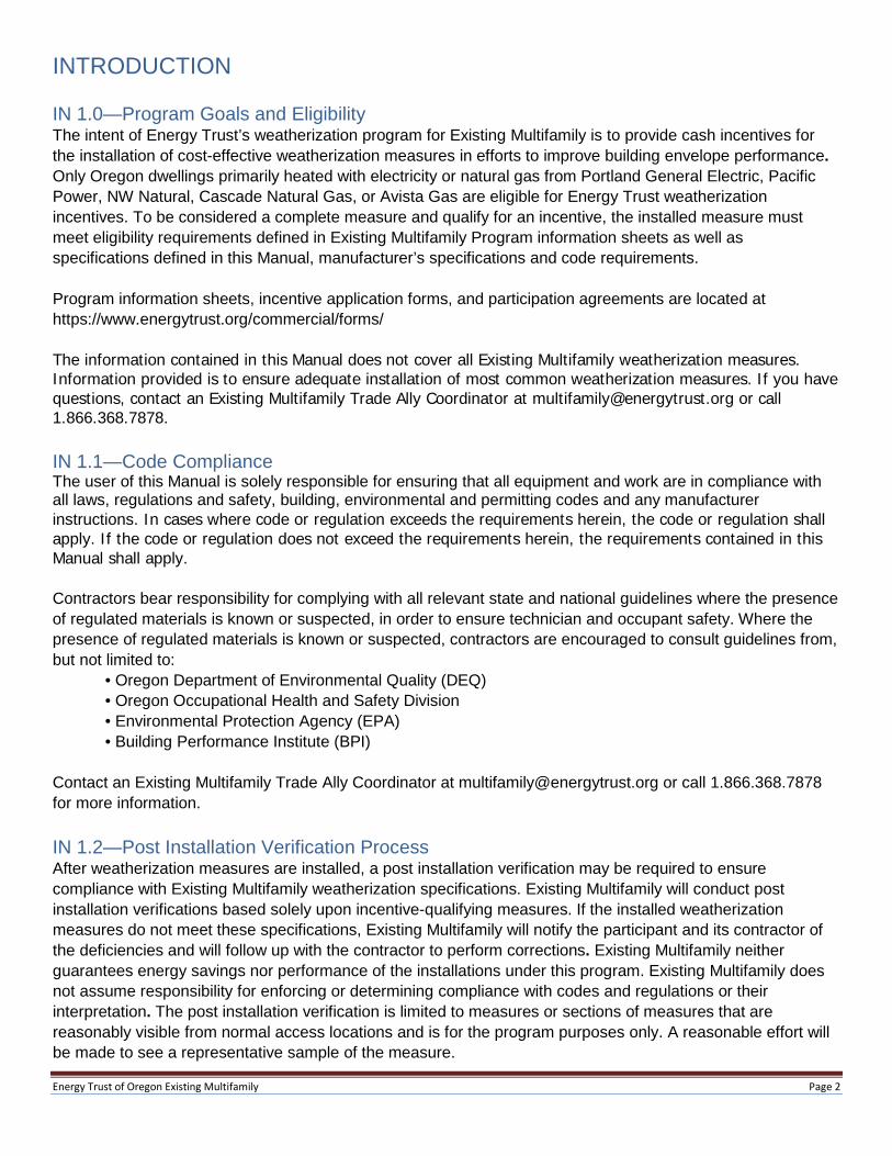
Illustration UN 1.1b
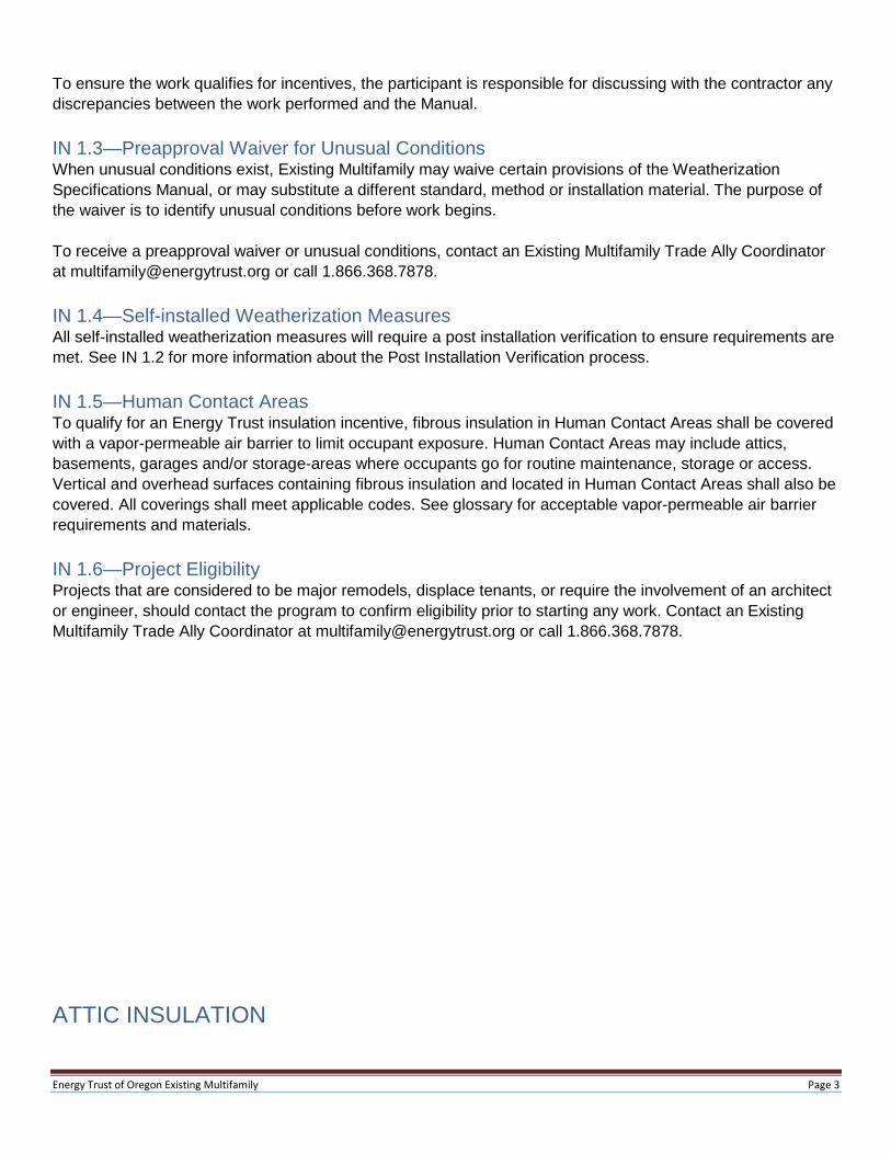
Insulation shall be supported so it does not block or restrict crawlspace ventilation. If necessary, insulation may be compressed to meet this requirement. UN 1.2—Floor Insulation Support Materials Use one of the following materials to support floor insulation: Wood lath—Wood lath shall be a minimum of ¼” x 1”. Twine—Twine shall be non-stretching polypropylene or polyester. Wire—Wire shall be stainless steel, copper or an equivalent material of similar corrosion resistance, with a minimum diameter of 0.040 inch (size 18 AWG). Self-supporting wire hangers are not acceptable. Hand stapling is not a durable fastening technique and will not qualify a project for an Energy Trust incentive. Fasteners for lath, twine or wire may be either hot-dipped galvanized nails, screws or corrosion-resistant staples that are at least 18-gauge and long enough to penetrate wood at least 5/8”.
Illustration UN 1.2
UN 1.3—Spacing Requirements for Support Systems Staples shall be driven with a power-actuated stapler to achieve at least 5/8” penetration. The maximum spacing for support systems is as follows:
Table UN 1.3
Energy Trust of Oregon Existing Multifamily Page 11
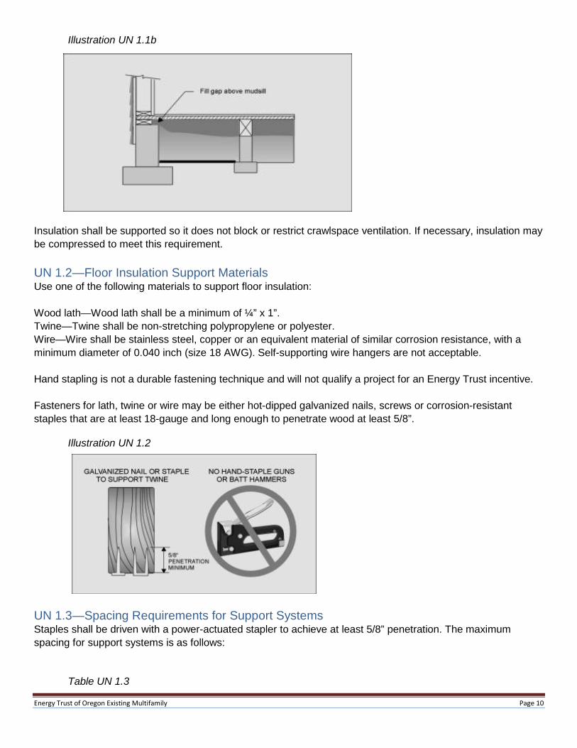
Spans Maximum Spacing
24” or less 18” apart 48” 12” apart 60” 8” apart 72” 6” apart
Wood lath shall not be used for spans greater than 48”. Splicing is not allowed to meet this requirement. Wood with a thicker dimension may be used for wider spans. Support systems for spans of over 72” or support systems not secured to the bottom of the joists require prior approval by Existing Multifamily. Batt-type insulation shall be supported no more than 3 inches from the ends. This support shall be parallel to the end of the batt. Small pieces of insulation shall be supported.
Illustration UN 1.3
Support systems shall be fastened to the underside of floor joists. Joists may be skipped; however, the maximum spacing shall not exceed 12”. The maximum span of skipped joists shall not exceed 48”.
Insulation shall be supported so that it is in direct contact with the bottom of the subfloor sheathing.

Energy Trust of Oregon Existing Multifamily Page 12
UN 1.4—Inside Access Doors for Underfloors All operable accesses between unconditioned and conditioned spaces shall be insulated to R-25 for floor hatches, and R-15 for doors in walls. Insulation shall be securely fastened to access doors using staples and twine or a similar method that ensures the effectiveness and durability of the insulation. Inside access doors shall be weather-stripped.
Illustration UN 1.4
Alternatively, R-5 or greater rigid insulation installed between the access cover and a rigid protective material (OSB, plywood or other durable rigid material) under the entire insulation area is allowed. Insulation must be sealed around the perimeter to the access cover using caulk, adhesive or spray foam. The rigid protective material must be mechanically attached to the access cover to securely hold insulation in place. Access cover assembly must be tightly sealed using weather-stripping around the entire perimeter. UN 1.5—Outside Access Doors for Underfloors Any outside access shall have a door which is easily opened to permit inspection, and shall be weather- and vermin-resistant. Vertical accesses may be screened when it is part of the crawl space ventilation system. Horizontal hatch covers shall shed water. Wood in contact with soil or concrete shall be pressure-treated. Existing covers are acceptable if they are in good condition, weather-resistant and vermin-resistant. UN 1.6—Installing Foam Insulation Spray foam insulation may be used for insulating an underfloor area either on its own or in combination with other insulation types (flash and batt). This assembly must meet the requirements for R-value, be in contact with the heated surface and comply with the thermal and ignition barrier requirements for foam plastics as defined by the prevailing jurisdictional building code. There shall be no gaps or voids in the insulation assembly and all other applicable underfloor specifications shall be met. Spray foam is exempt from support requirements. When used in combination with other insulation types, spray foam shall be installed in contact with the heated surface of the unit. UN 1.7—Miscellaneous Underfloor Specifications Underfloor areas which allow easy human access must comply with the requirements defined in IN 1.5 Human Contact Areas to protect occupants from encountering fibrous insulation in areas where routine storage or maintenance occurs. Basements with exposed soil or earth shall have a ground cover installed on exposed areas.

Energy Trust of Oregon Existing Multifamily Page 13
WINDOWS AND PATIO DOORS WI 1.0—Introduction Window requirements shall apply to patio doors unless otherwise stated. Windows shall be installed and supported according to the manufacturer’s specifications. If window-weight cavities exist and are accessible, the weights shall be removed and the cavity shall be filled with insulation. Windows shall be reasonably sealed to prevent air infiltration. All incentive-qualifying windows must meet the applicable requirements—unless a waiver is approved in advanced by Existing Multifamily (see section IN 1.3)—to be considered a complete measure. Windows shall be installed to prevent heat loss from a conditioned space to the outside of the unit. Basements containing HVAC ducts or which have a direct access to the interior conditioned space of a unit shall be considered conditioned space. Overview of requirements for all window projects:
• Safety glazing shall be used where required by current state code. • Windows shall operate smoothly and safely. • Screens shall be furnished with all operable windows. • Exterior wood, including frame, sash, trim, stops and sills shall be, at a minimum, caulked and
primed. • Hardware and fasteners shall be aluminum, stainless steel or other noncorrosive materials. • Gaps of over 3/8” between the exterior siding and the window shall be covered with solid trim
material. Exterior or interior voids over 3/8” in depth or width shall be filled with window-manufacturer approved materials, such as backer rod, nonexpanding foam or similar product prior to caulking, if caulking will be applied.
• Interior window trim should be replaced if signs of past moisture are present. The surrounding two-foot area around the exterior of a window shall have no unpainted wood. Louvered windows are not eligible for Existing Multifamily incentives.
Window incentives shall be calculated only for windows of the original dimensions, except when window area must be increased to meet egress requirement. Windows must be installed between conditioned and unconditioned space. Windows installed between unconditioned garages and the exterior of the unit will not qualify. Qualifying windows shall meet U-Value requirements detailed by the current program information document. Existing Multifamily requires documentation of window dimensions and U-Value for each qualifying window installed.

Energy Trust of Oregon Existing Multifamily Page 14
Glossary
Air barrier-A continuous barrier to air movement which separates interior (conditioned) space from exterior (unconditioned) space. An air barrier is created by sealing all penetrations to unconditioned space with durable Materials as well as possible.
ASTM E-136-A rating for noncombustible materials. Examples include sheet metal and rated caulks. These materials are appropriate for air sealing around a chimney or flue. Products meeting this rating will have the ASTM E 136 rating on the label. No foam meets this rating.
ASTM E-814-A rating for an assembly of materials that inhibits the spread of fire and hot gases through a unit. Examples include gypsum board and ASTM E-814 rated foams and caulks. These materials are appropriate for air sealing, and may be required by code in some locations. Note: some foam products may say fire-stop or fire-block on the label but are not ASTM E-136 rated and should not be used on a chimney or flue. Foam is combustible. Baffles-Rigid material used to contain loose-fill insulation. Complete measure-An installation of an Energy Trust incentivize-qualifying measure which meets all requirements in the Weatherization Specifications Manual and the minimum requirements at all reasonably accessible locations. For example, attic insulation must be R-49 over the entire surface adjacent to conditioned space and ducts must be sealed at every joint and seam. Conditioned basement-Any basement containing HVAC ducts and/or is accessible from another conditioned space. Other basements may be considered conditioned if they are largely connected to the conditioned space of the house and separated from the outside. Conditioned space-Enclosed areas that directly receive space conditioning, meaning they contain HVAC vents, electric-resistance heaters or wood stoves. Alternatively, spaces which are not directly conditioned but are largely connected to a conditioned space and have an effective barrier from the outside shall be considered conditioned. Garages are usually considered unconditioned space, unless there is a vent feeding conditioned air to the area. Faced batt-type insulation-Faced batts have an air and/or vapor barrier on one side, usually made of kraft paper. The facing shall always be placed adjacent to the warm surface being insulated and shall not be sandwiched between insulation or installed, which creates a condensing surface on the cold side of the insulation. Ground cover-Six-mil or thicker, black polyethylene used to prevent water vapor from emanating from soil in unfinished crawlspaces or basements. Human contact area-Location where occupants go for routine maintenance or storage. HVAC—Heating, Ventilation and Air Conditioning. Refers to components of a home’s mechanical systems that provide space heating and cooling. IC vs. Non-IC-rated light fixtures-Insulation contact-rated fixtures does not need to be baffled to prevent insulation from contact. Insulation may be piled directly on top of fixture. Non-IC-rated fixtures must be baffled to prevent heat buildup.
Energy Trust of Oregon Existing Multifamily Page 15
ICAT fixture-Is a type of IC-rated fixture that is manufactured as an airtight unit that does not need to be baffled to prevent insulation from contact. Interior attic access-Entry into unconditioned attic space directly connected to a conditioned area. Knee wall-A short wall between an attic floor and a sloping roof, and which separates a conditioned and unconditioned space. Net free area (NFA)—The net area of properly-baffled passive ventilation, meaning the total area of the vent minus the area blocked by screens or louvers. Open wall(s)-Any vertical barrier between conditioned and unconditioned space where the framing is visible from any side. Passive ventilation-Natural ventilation of a space caused by wind or temperature-driven convection. Does not include moving parts such as fans. R-value—Measurement of a material’s thermal resistance, commonly used to describe insulation materials. An increase in R-value results in an increase in thermal resistance. R-value is the inverse of U-value (R = 1/U). Rim or band joist—Area of a unit where the concrete foundation meets the floor joists. Spray-foam insulation—A foam-plastic material applied with a foaming agent for use as insulation. Unconditioned space-Space within a building that is not heated or cooled by an active system or directly linked to conditioned space; outside. U-value—Measurement of a material’s thermal transmission, commonly used to describe windows, doors and skylights. A decrease in U-value results in a decrease in thermal transmission. U-value is the inverse of R-value (U = 1/R). Unfaced batt-type insulation-Batt-type insulation with no vapor or air barrier attached. Vapor-permeable air barrier-Any material—including house wraps—that substantively blocks air from passing but allows water vapor (which may pass through narrower pores than air) to pass through. Vapor barrier- A material restricting the movement of water vapor from an area of high vapor pressure to one of lower pressure. Material with a perm rating of 1.0 or less is normally considered a vapor barrier. Weatherization measure - Installation of insulation and/or windows.