2018 cams manual of motor sportdocs.cams.com.au/manual/rally/2018 edition/rr21-cams...2018 cams...
TRANSCRIPT

2018 CAMS MANUAL OF MOTOR SPORT
CONFEDERATION OF AUSTRALIAN MOTOR SPORT
WWW.CAMS.COM.AU
RALLY/ROAD GROUP AP4 TECHNICAL REGULATIONS
GROUP AP4 TECHNICAL REGULATIONS Last updated: 07/02/2018 1
© Confederation of Australian Motor Sport Ltd. All use subject to Conditions of Use at www.cams.com.au
1. PART ONE – BUILD PROCESS
1.1 Philosophy Motor Sport New Zealand (MSNZ) and the Confederation of Australian Motor Sport (CAMS) have collaboratively developed these Technical Regulations for a new generation of 4WD turbocharged rally car eligible for competition in both National and International events within the Asia Pacific region. The philosophy of AP4 is to establish a set of technical articles that allow rally teams to build locally, or buy cars of parallel design from overseas, that will be of a similar specification and performance to each other and to that of the FIA R5 / S2000 Category cars, but at significantly lower cost. The main focus in developing these technical articles is to allow commercial competitive freedoms in the supply of control parts – which are primarily limited to only those parts deemed to affect performance, reliability and safety – while ensuring sufficient control exists to equalise performance and prevent unnecessarily wasteful development. The build process should be flexible enough to accommodate the specific requirements and skills of individual teams without compromising the quality standards necessary at this level of competition. Providing an opportunity for local construction and component supply has the potential to insulate competitors from fluctuations in international exchange rates, enables lower inventory costs and shorter delivery times. Having multiple vehicles with many ‘common’ components also allows teams to reduce their spares inventory. When combined with regional acceptance of the category, these are powerful incentives to build a car compliant with these specifications. Component parts fall into 4 categories; being series parts, free parts, control parts and control design parts, all of which are defined in PART TWO of these regulations. Part One (herein under) provides an outline of the steps involved in ‘building’ (or obtaining) an AP4 Rally Car, Part Two provides the specific technical regulations for an AP4 Rally Car and Part Three lists the ‘approved constructors/parties’ involved and listings of the mandatory ‘control parts’ necessary to build an AP4 Rally Car. 1.2 Build Process An AP4 Rally Car may be built under the observation and approval of an ASN in New Zealand (MSNZ) or Australia (CAMS) or in another Country, in conjunction with the relevant ASN, with the approval of MSNZ / CAMS to the specifications detailed in PART TWO of these regulations or purchased in part or as a complete car (refer below). Cars built locally are subject to the bodyshell platform and safety cage being fabricated by an ‘approved constructor’ and common ‘control parts’ being supplied through the nominated companies as detailed in PART THREE of these regulations. Simplistically, the build process is as follows;
Modified Article Date of Application Date of Publication
GROUP AP4 TECHNICAL REGULATIONS Last updated: 07/02/2018 2
© Confederation of Australian Motor Sport Ltd. All use subject to Conditions of Use at www.cams.com.au
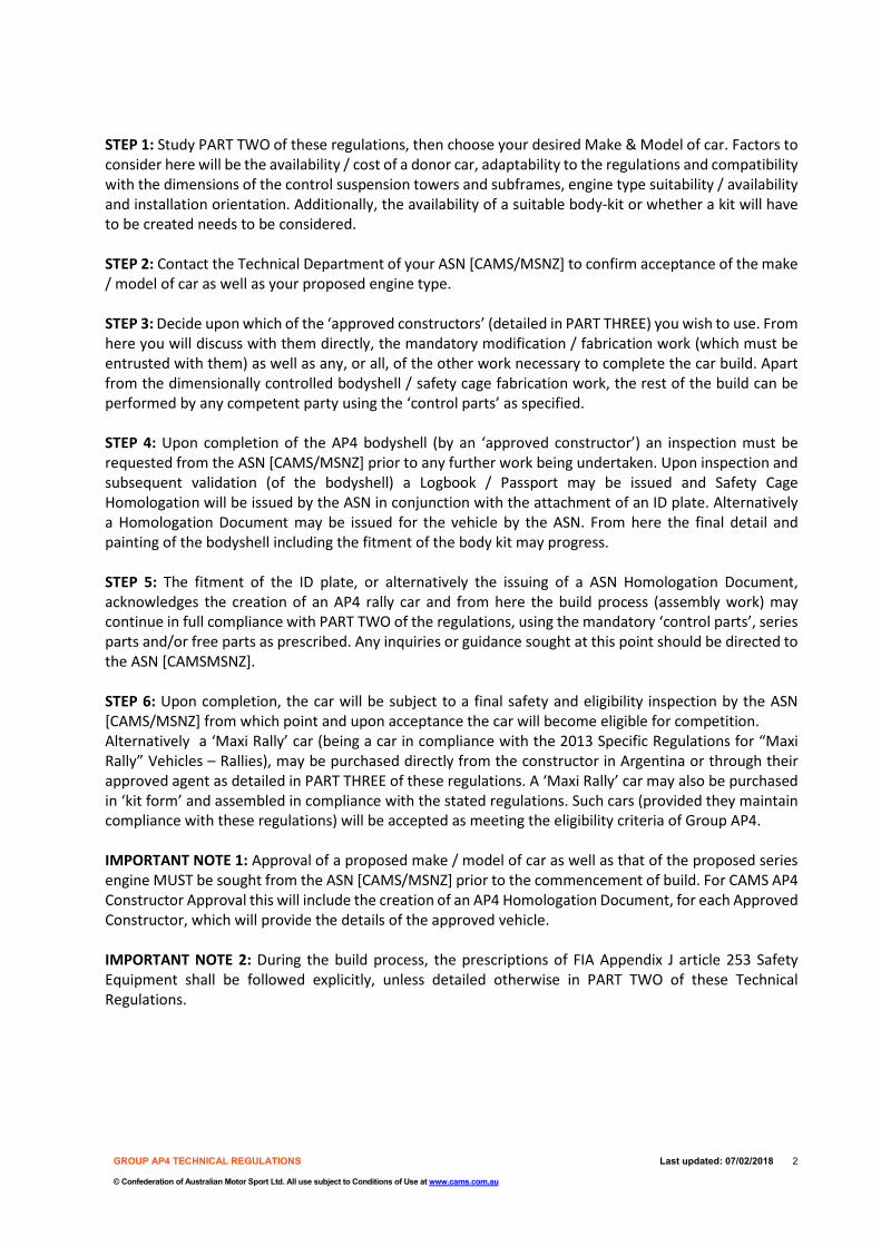
STEP 1: Study PART TWO of these regulations, then choose your desired Make & Model of car. Factors to consider here will be the availability / cost of a donor car, adaptability to the regulations and compatibility with the dimensions of the control suspension towers and subframes, engine type suitability / availability and installation orientation. Additionally, the availability of a suitable body-kit or whether a kit will have to be created needs to be considered. STEP 2: Contact the Technical Department of your ASN [CAMS/MSNZ] to confirm acceptance of the make / model of car as well as your proposed engine type. STEP 3: Decide upon which of the ‘approved constructors’ (detailed in PART THREE) you wish to use. From here you will discuss with them directly, the mandatory modification / fabrication work (which must be entrusted with them) as well as any, or all, of the other work necessary to complete the car build. Apart from the dimensionally controlled bodyshell / safety cage fabrication work, the rest of the build can be performed by any competent party using the ‘control parts’ as specified. STEP 4: Upon completion of the AP4 bodyshell (by an ‘approved constructor’) an inspection must be requested from the ASN [CAMS/MSNZ] prior to any further work being undertaken. Upon inspection and subsequent validation (of the bodyshell) a Logbook / Passport may be issued and Safety Cage Homologation will be issued by the ASN in conjunction with the attachment of an ID plate. Alternatively a Homologation Document may be issued for the vehicle by the ASN. From here the final detail and painting of the bodyshell including the fitment of the body kit may progress. STEP 5: The fitment of the ID plate, or alternatively the issuing of a ASN Homologation Document, acknowledges the creation of an AP4 rally car and from here the build process (assembly work) may continue in full compliance with PART TWO of the regulations, using the mandatory ‘control parts’, series parts and/or free parts as prescribed. Any inquiries or guidance sought at this point should be directed to the ASN [CAMSMSNZ]. STEP 6: Upon completion, the car will be subject to a final safety and eligibility inspection by the ASN [CAMS/MSNZ] from which point and upon acceptance the car will become eligible for competition. Alternatively a ‘Maxi Rally’ car (being a car in compliance with the 2013 Specific Regulations for “Maxi Rally” Vehicles – Rallies), may be purchased directly from the constructor in Argentina or through their approved agent as detailed in PART THREE of these regulations. A ‘Maxi Rally’ car may also be purchased in ‘kit form’ and assembled in compliance with the stated regulations. Such cars (provided they maintain compliance with these regulations) will be accepted as meeting the eligibility criteria of Group AP4. IMPORTANT NOTE 1: Approval of a proposed make / model of car as well as that of the proposed series engine MUST be sought from the ASN [CAMS/MSNZ] prior to the commencement of build. For CAMS AP4 Constructor Approval this will include the creation of an AP4 Homologation Document, for each Approved Constructor, which will provide the details of the approved vehicle. IMPORTANT NOTE 2: During the build process, the prescriptions of FIA Appendix J article 253 Safety Equipment shall be followed explicitly, unless detailed otherwise in PART TWO of these Technical Regulations.
GROUP AP4 TECHNICAL REGULATIONS Last updated: 07/02/2018 3
© Confederation of Australian Motor Sport Ltd. All use subject to Conditions of Use at www.cams.com.au
2. PART TWO – TECHNICAL REGULATIONS AP
4 Ar
ticle
No.
&
FIA
Refe
renc
e N
o.
Cate
gory
of
Com
pone
nt p
art.
REGULATION
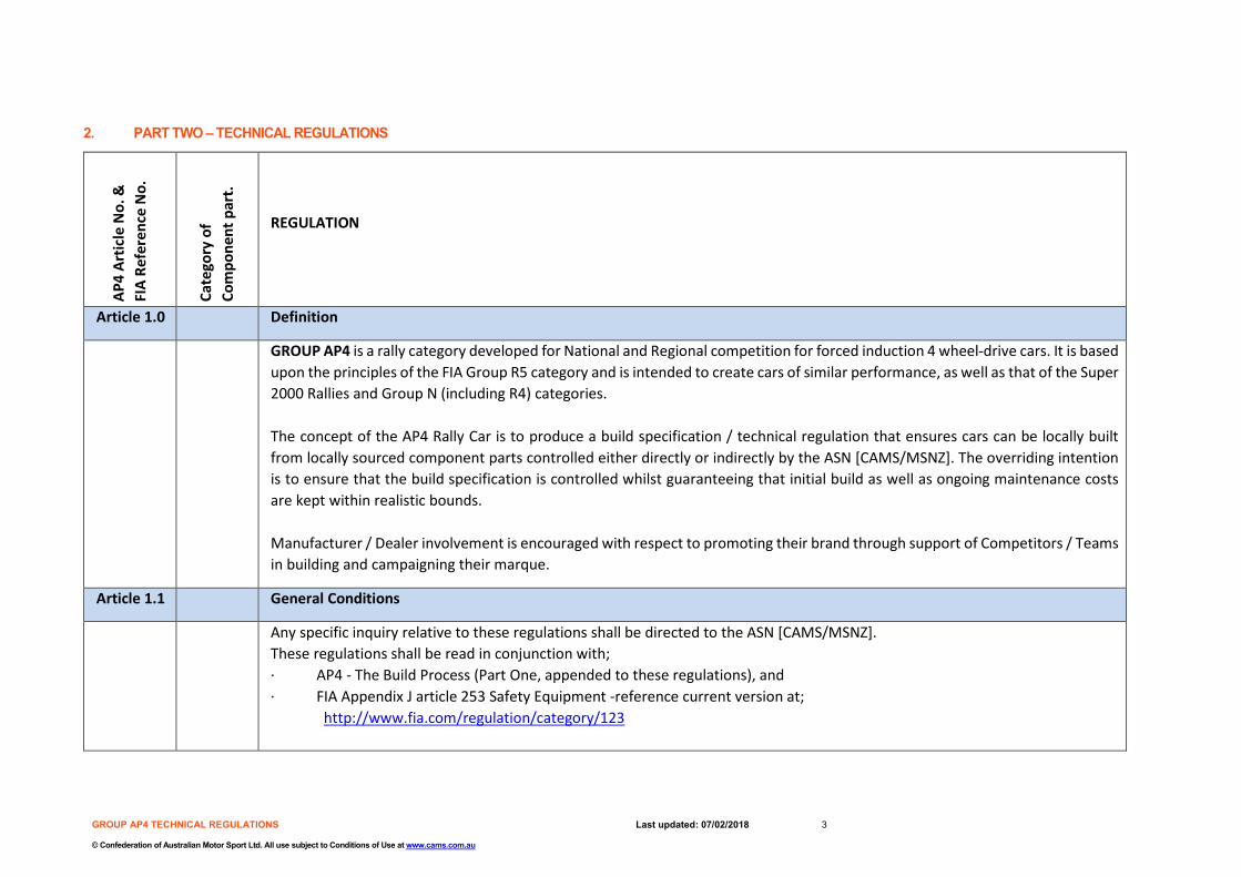
Article 1.0 Definition
GROUP AP4 is a rally category developed for National and Regional competition for forced induction 4 wheel-drive cars. It is based upon the principles of the FIA Group R5 category and is intended to create cars of similar performance, as well as that of the Super 2000 Rallies and Group N (including R4) categories. The concept of the AP4 Rally Car is to produce a build specification / technical regulation that ensures cars can be locally built from locally sourced component parts controlled either directly or indirectly by the ASN [CAMS/MSNZ]. The overriding intention is to ensure that the build specification is controlled whilst guaranteeing that initial build as well as ongoing maintenance costs are kept within realistic bounds. Manufacturer / Dealer involvement is encouraged with respect to promoting their brand through support of Competitors / Teams in building and campaigning their marque.
Article 1.1 General Conditions
Any specific inquiry relative to these regulations shall be directed to the ASN [CAMS/MSNZ]. These regulations shall be read in conjunction with; · AP4 - The Build Process (Part One, appended to these regulations), and · FIA Appendix J article 253 Safety Equipment -reference current version at;
http://www.fia.com/regulation/category/123

GROUP AP4 TECHNICAL REGULATIONS Last updated: 07/02/2018 4
© Confederation of Australian Motor Sport Ltd. All use subject to Conditions of Use at www.cams.com.au
A national vehicle Logbook / Passport, issued by the ASN [CAMS/MSNZ] is mandatory. The Logbook / Passport shall be issued upon inspection and approval of the completed AP4 bodyshell [refer article 9.0] and approval of the engine type [refer article 2.2]. AP4 cars used in rallies (on open roads) must be legally registered for road use; hence all national road transport legislation must be complied with. For Australia this will require the approval of a relevant State or Territory Rally Vehicle Registration Scheme or similar.
Article 2.0
Homologation
The basis of the AP4 Rally Car is a Series Production Vehicle, meaning a vehicle (model) that has been manufactured in a certain number of identical examples using series production methods destined for public road use and available through the normal commercial channels of the manufacturer. Eligible cars (base model) do not necessarily have to appear on the list of FIA homologations issued by the FIA. Technical information and specifications shall be sourced either from the FIA Homologation Form (where the model is homologated) or directly from the car manufacturer for the model concerned. An ASN (CAMS / MSNZ) may issue AP4 Homologation documents for a specific AP4 Constructor for a model/make of vehicle and for a specific constructor of AP4 Control Components. Note: Cars [built to and in compliance with these regulations] may be accepted in International Rallies within the Asia Pacific region where authorised by the Regional Rally Sporting Regulations and/or approved by the APRC Secretariat (refer APRC National Vehicle Approval Form).
Article 2.1
Eligible cars
Large Scale Series Production Touring Cars of; - either 2 or 4 door bodyshell configuration, - either left or right-hand drive configuration, and - at least four factory seating positions; according to the dimensions defined under FIA Group A.
Article 2.2

GROUP AP4 TECHNICAL REGULATIONS Last updated: 07/02/2018 5
© Confederation of Australian Motor Sport Ltd. All use subject to Conditions of Use at www.cams.com.au
SP Either a “Series Production Engine” or the “AP4 Designated Joker Engine” are authorised, under the following conditions: 4 cylinder up to a maximum capacity of 1620* cm3 (being 2754 cm3 with 1.7 forced induction coefficient applied). Note: The bore/stroke may be adjusted to achieve the designated 1620 cm3 capacity. At least 2500 identical engine units must have been produced in 12 consecutive months. It will be possible to count models from another manufacturer, provided that they are equipped with the same engine (strictly identical) and produced in a quantity of at least 5000 units in 12 consecutive months. The AP4 designated engine is:
- EP6 ‘Prince’ series 1598cc turbocharged engine Note1: Under these regulation’s a “Series Production Engine” is defined as; any engine fitted to a (model of car) from that manufacturer that is/has been on sale to the general public and/or an engine fitted to a (model of car) from another manufacturer that utilises the same common construction platform. All engine proposals will be subject to approval through the respective ASN prior to becoming eligible for use under these regulations. Note2: The “AP4 Designated Joker Engine” may be utilised as an alternative to the “Series Production Engine”. Note3: National Series Regulations may authorise other engines and capacity options.
Article 2.3
Component Parts
Component parts of the car are classified as follows and identified in the column to the left of the applicable article;
SP Series Part; being original parts or replacement parts identical to the original parts as fitted to the car / engine at the time of manufacture or subsequently replaced due to use or accident. All such parts shall be available through the original car manufacturer’s dealer network. All relevant specifications shall be referenced from the manufacturers’ official data or applicable FIA homologation form. Note: A series production engine or the AP4 designated engine shall be classified as a ‘Series Part’.
GROUP AP4 TECHNICAL REGULATIONS Last updated: 07/02/2018 6
© Confederation of Australian Motor Sport Ltd. All use subject to Conditions of Use at www.cams.com.au
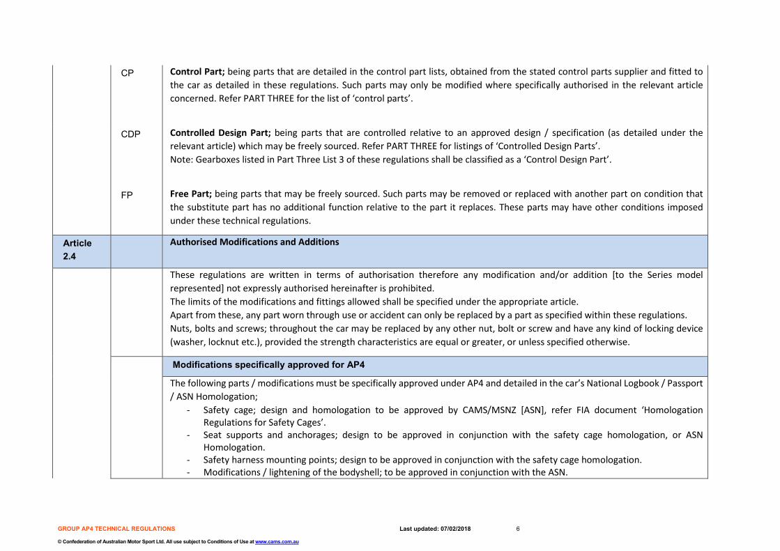
CP Control Part; being parts that are detailed in the control part lists, obtained from the stated control parts supplier and fitted to the car as detailed in these regulations. Such parts may only be modified where specifically authorised in the relevant article concerned. Refer PART THREE for the list of ‘control parts’.
CDP Controlled Design Part; being parts that are controlled relative to an approved design / specification (as detailed under the relevant article) which may be freely sourced. Refer PART THREE for listings of ‘Controlled Design Parts’. Note: Gearboxes listed in Part Three List 3 of these regulations shall be classified as a ‘Control Design Part’.
FP Free Part; being parts that may be freely sourced. Such parts may be removed or replaced with another part on condition that the substitute part has no additional function relative to the part it replaces. These parts may have other conditions imposed under these technical regulations.
Article 2.4
Authorised Modifications and Additions
These regulations are written in terms of authorisation therefore any modification and/or addition [to the Series model represented] not expressly authorised hereinafter is prohibited. The limits of the modifications and fittings allowed shall be specified under the appropriate article. Apart from these, any part worn through use or accident can only be replaced by a part as specified within these regulations. Nuts, bolts and screws; throughout the car may be replaced by any other nut, bolt or screw and have any kind of locking device (washer, locknut etc.), provided the strength characteristics are equal or greater, or unless specified otherwise.
Modifications specifically approved for AP4
The following parts / modifications must be specifically approved under AP4 and detailed in the car’s National Logbook / Passport / ASN Homologation;
- Safety cage; design and homologation to be approved by CAMS/MSNZ [ASN], refer FIA document ‘Homologation Regulations for Safety Cages’.
- Seat supports and anchorages; design to be approved in conjunction with the safety cage homologation, or ASN Homologation.
- Safety harness mounting points; design to be approved in conjunction with the safety cage homologation. - Modifications / lightening of the bodyshell; to be approved in conjunction with the ASN.
GROUP AP4 TECHNICAL REGULATIONS Last updated: 07/02/2018 7
© Confederation of Australian Motor Sport Ltd. All use subject to Conditions of Use at www.cams.com.au
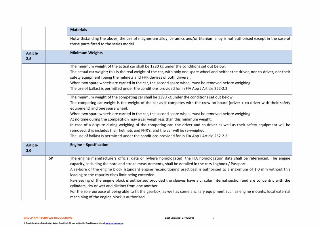
Materials
Notwithstanding the above, the use of magnesium alloy, ceramics and/or titanium alloy is not authorised except in the case of those parts fitted to the series model.
Article 2.5
Minimum Weights
The minimum weight of the actual car shall be 1230 kg under the conditions set out below; The actual car weight; this is the real weight of the car, with only one spare wheel and neither the driver, nor co-driver, nor their safety equipment (being the helmets and FHR devises of both drivers). When two spare wheels are carried in the car, the second spare wheel must be removed before weighing. The use of ballast is permitted under the conditions provided for in FIA App J Article 252-2.2.
The minimum weight of the competing car shall be 1390 kg under the conditions set out below; The competing car weight is the weight of the car as it competes with the crew on-board (driver + co-driver with their safety equipment) and one spare wheel. When two spare wheels are carried in the car, the second spare wheel must be removed before weighing. At no time during the competition may a car weigh less than this minimum weight. In case of a dispute during weighing of the competing car, the driver and co-driver as well as their safety equipment will be removed; this includes their helmets and FHR’s, and the car will be re-weighed. The use of ballast is permitted under the conditions provided for in FIA App J Article 252-2.2.
Article 3.0
Engine – Specification
SP The engine manufacturers official data or [where homologated] the FIA homologation data shall be referenced. The engine capacity, including the bore and stroke measurements, shall be detailed in the cars Logbook / Passport. A re-bore of the engine block [standard engine reconditioning practices] is authorised to a maximum of 1.0 mm without this leading to the capacity class limit being exceeded. Re-sleeving of the engine block is authorised provided the sleeves have a circular internal section and are concentric with the cylinders, dry or wet and distinct from one another. For the sole purpose of being able to fit the gearbox, as well as some ancillary equipment such as engine mounts, local external machining of the engine block is authorised.

GROUP AP4 TECHNICAL REGULATIONS Last updated: 07/02/2018 8
© Confederation of Australian Motor Sport Ltd. All use subject to Conditions of Use at www.cams.com.au
Engine fasteners {screws, bolts, studs, nuts etc.} may be changed provided that the replacements are made from ferrous material.
Engine Performance Controls
SP Engine performance shall be regulated. This is to be controlled by; - Engine (air) restrictor, and/or - Car weight.
Additionally (at a later date) the following controls may be introduced; - Throttle valve size, and/or - FIA boost control system, and/or - Control ECU.
Note: Engine performance shall be aligned to the current FIA Group R5 power to weight ratio.
301 Engine Position and Mountings
The engine may be orientated in either a longitudinal or transverse position under the following conditions; - The engine may be moved in its compartment in relation to the series model although it may not be moved outside of the
parameters of the original compartment, - The top 1/3rd (section) of the bulkhead shall not be modified / changed in order to accommodate engine placement, save
that: o Manufacturer installed brackets may be removed; and o Manufacturer moulded pressings and forming’s may be trimmed or removed no further reward than the
predominant plane of the bulkhead panel. Note: The bulkhead is defined as the panel that extends from the horizontal floor-pan to the bottom of the windscreen aperture. Reference diagram below:
GROUP AP4 TECHNICAL REGULATIONS Last updated: 07/02/2018 9
© Confederation of Australian Motor Sport Ltd. All use subject to Conditions of Use at www.cams.com.au
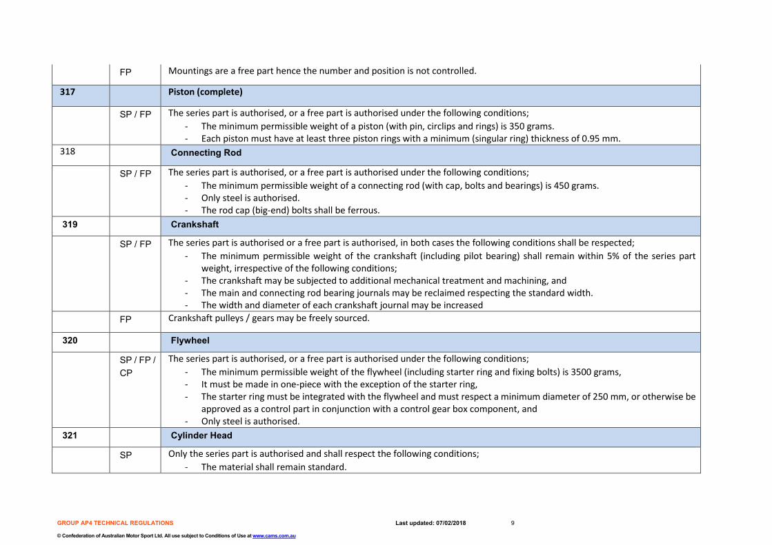
FP Mountings are a free part hence the number and position is not controlled.
317 Piston (complete)
SP / FP The series part is authorised, or a free part is authorised under the following conditions; - The minimum permissible weight of a piston (with pin, circlips and rings) is 350 grams. - Each piston must have at least three piston rings with a minimum (singular ring) thickness of 0.95 mm.
318 Connecting Rod
SP / FP The series part is authorised, or a free part is authorised under the following conditions; - The minimum permissible weight of a connecting rod (with cap, bolts and bearings) is 450 grams. - Only steel is authorised. - The rod cap (big-end) bolts shall be ferrous.
319 Crankshaft
SP / FP The series part is authorised or a free part is authorised, in both cases the following conditions shall be respected; - The minimum permissible weight of the crankshaft (including pilot bearing) shall remain within 5% of the series part
weight, irrespective of the following conditions; - The crankshaft may be subjected to additional mechanical treatment and machining, and - The main and connecting rod bearing journals may be reclaimed respecting the standard width. - The width and diameter of each crankshaft journal may be increased
FP Crankshaft pulleys / gears may be freely sourced.
320 Flywheel
SP / FP / CP
The series part is authorised, or a free part is authorised under the following conditions; - The minimum permissible weight of the flywheel (including starter ring and fixing bolts) is 3500 grams, - It must be made in one-piece with the exception of the starter ring, - The starter ring must be integrated with the flywheel and must respect a minimum diameter of 250 mm, or otherwise be
approved as a control part in conjunction with a control gear box component, and - Only steel is authorised.
321 Cylinder Head
SP Only the series part is authorised and shall respect the following conditions; - The material shall remain standard.

GROUP AP4 TECHNICAL REGULATIONS Last updated: 07/02/2018 10
© Confederation of Australian Motor Sport Ltd. All use subject to Conditions of Use at www.cams.com.au
- The valve seats as well as the valve guides are free although the respective (operating) angles of the valves shall not be changed.
- The gasket face (plane) may be re-surfaced by a maximum of 1 mm (for adjusting the compression ratio). 322 Cylinder head gasket
FP The cylinder head gasket may be freely sourced.
324 Injection System
SP / FP The series part (system) is authorised, or a new system may be accepted under the following criteria; - The maximum number of injectors shall be equal to the number of cylinders, or the number fitted to the series engine. - A new injector rail of free design is authorised, fitted with threaded connectors for connecting the lines and the fuel
pressure regulator. - Any other additional injection system (such as water) is prohibited.
324 (d) Throttle Valve Housing
SP / FP The series part (throttle valve housing) is authorised, or a free part is authorised. The following conditions apply; - Only a single throttle body is authorised, - The maximum opening size (at the butterfly) is 64 mm +/- 0.25 mm, - The housing may be modified externally but not the diameter of the opening of the butterfly, and - The housing mounting ‘bolts’ shall be drilled for the possible application of wire seals.
CP Note: Additionally, (at a later date) a ‘control part’ throttle valve housing may be introduced (refer article 3.0 engine performance controls).
324 (h) ECU / Sensors / Actuators / Data acquisitions
SP / FP The series ECU (system) is authorised, or a freely sourced ECU may be accepted under the following criteria; - The ECU is a commercially available system from a recognised manufacturer, and - All actuators must be controlled by the ECU.
CP Note: Additionally (at a later date) a ‘control part’ ECU may be introduced (refer article 3.0 engine performance controls)
FP Wiring looms are free.
325 Camshaft
SP / FP The series part is authorised, or a free part is authorised under the following conditions;

GROUP AP4 TECHNICAL REGULATIONS Last updated: 07/02/2018 11
© Confederation of Australian Motor Sport Ltd. All use subject to Conditions of Use at www.cams.com.au
- The maximum lift for the inlet valves shall be 11 mm, - The maximum lift for the exhaust valves shall be 11 mm, and - The number of camshaft must remain unchanged.
327 Intake manifold
SP / FP The series part (intake manifold) is authorised, or a free part is authorised. The following conditions apply; - In both cases modification to the manifold is unrestricted.
327 Intake valves
SP / FP The series parts and dimensions shall be retained. Direct replacement valves are authorised provided they respect the same dimensions and are sourced from a recognised manufacturer of valves.
328 Exhaust Valves
SP / FP The series parts and dimensions shall be retained. Direct replacement valves are authorised provided they respect the same dimensions and are sourced from a recognised manufacturer of valves.
328 Exhaust Manifold
SP / FP The series part (exhaust manifold) is authorised, or a free part is authorised under the following conditions; - Only steel, stainless steel or cast iron is authorised.
328 Exhaust System
FP The exhaust system is free downstream of the turbocharger, provided it respects the following criteria; - Fitment does not entail the modification of other components, (except floorpan as per bodyshell approval), - The exit of the exhaust pipe shall be at the rear of the car, and - The noise levels must respect the stated maximum prescribed by the ASN of the country where the car competes.
329 Balancing Shafts
If the series engine was fitted with balancing shafts, these may be removed together with their drive system.
330 Ignition System
SP / FP The make and type of spark plugs, ignition coils, rev limiter and leads are free.

GROUP AP4 TECHNICAL REGULATIONS Last updated: 07/02/2018 12
© Confederation of Australian Motor Sport Ltd. All use subject to Conditions of Use at www.cams.com.au
331 Cooling System
SP / FP The series part (water pump) is authorised, or a free part is authorised under the following conditions; - The pump is either mechanically or electrically driven, and - The pump is located in the engine compartment.
SP / FP The series part (water radiator) is authorised, or a freely sourced part is authorised provided it remains within the engine compartment.
FP Coolant hoses may be freely sourced.
FP An expansion (header) tank is authorised as are ‘air-bleeds’.
333 Lubrication System
SP / FP The series part (oil sump) is authorised, or a free part is authorised under the following conditions; - It is made from either steel sheet or aluminium, - Its sole function must be that of containing oil.
SP / FP The series part (oil pump) is authorised or a free part is authorised under the following conditions; - The (oil) pressure regulation system may be modified, and - A system (pressure pipe with fittings from a connection on the engine block, or the cylinder head, to the turbo charger
and a reverse pipe from the turbo charger to the oil sump or engine block) to lubricate the turbo may be added. FP An alternative engine breather system is authorised including the fitment of a supplementary breather tank.
Series emission control equipment may be removed.
334 Turbocharger
SP / FP The series part is authorised, or a free part is authorised under the following conditions; - The turbocharger assembly shall come from a recognised manufacturer of turbochargers (produced in a quantity of at
least 2500 units), - The turbocharger must be a single unit, with single stage compression and expansion, and must not have variable pitch
or variable geometry. FP An adapter is authorised between the exhaust manifold and the turbocharger on condition that the thickness of this component
is less than 30 mm.
GROUP AP4 TECHNICAL REGULATIONS Last updated: 07/02/2018 13
© Confederation of Australian Motor Sport Ltd. All use subject to Conditions of Use at www.cams.com.au
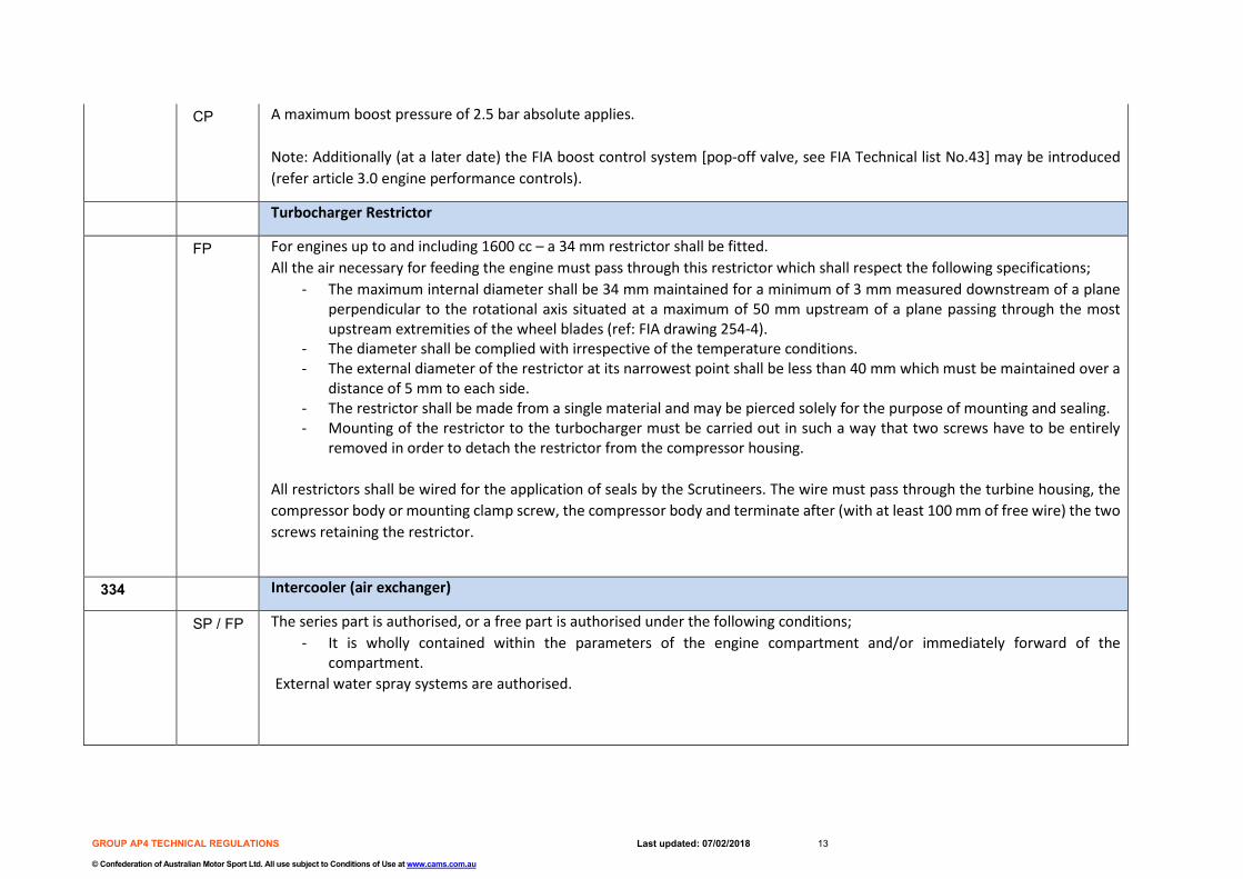
CP A maximum boost pressure of 2.5 bar absolute applies. Note: Additionally (at a later date) the FIA boost control system [pop-off valve, see FIA Technical list No.43] may be introduced (refer article 3.0 engine performance controls).
Turbocharger Restrictor
FP For engines up to and including 1600 cc – a 34 mm restrictor shall be fitted. All the air necessary for feeding the engine must pass through this restrictor which shall respect the following specifications;
- The maximum internal diameter shall be 34 mm maintained for a minimum of 3 mm measured downstream of a plane perpendicular to the rotational axis situated at a maximum of 50 mm upstream of a plane passing through the most upstream extremities of the wheel blades (ref: FIA drawing 254-4).
- The diameter shall be complied with irrespective of the temperature conditions. - The external diameter of the restrictor at its narrowest point shall be less than 40 mm which must be maintained over a
distance of 5 mm to each side. - The restrictor shall be made from a single material and may be pierced solely for the purpose of mounting and sealing. - Mounting of the restrictor to the turbocharger must be carried out in such a way that two screws have to be entirely
removed in order to detach the restrictor from the compressor housing.
All restrictors shall be wired for the application of seals by the Scrutineers. The wire must pass through the turbine housing, the compressor body or mounting clamp screw, the compressor body and terminate after (with at least 100 mm of free wire) the two screws retaining the restrictor.
334 Intercooler (air exchanger)
SP / FP The series part is authorised, or a free part is authorised under the following conditions; - It is wholly contained within the parameters of the engine compartment and/or immediately forward of the
compartment. External water spray systems are authorised.

GROUP AP4 TECHNICAL REGULATIONS Last updated: 07/02/2018 14
© Confederation of Australian Motor Sport Ltd. All use subject to Conditions of Use at www.cams.com.au
Article 4.0
Fuel System
401 CDP The fuel tank must come from an FIA-approved manufacturer and be compliant with FIA - FT3 1999 minimum specifications. The tank shall have a maximum capacity of 110 litres and the use of safety foam is recommended. The location of the fuel tank and pumps must respect the following conditions;
- The tank must be situated in the cockpit in the rear seat area, - The floorpan [in the rear seat area] may be modified in order to install the tank; the maximum dimensions of the resulting
hole in the floorpan are 1000 x 500 mm and the floorpan longitudinal rails shall not be modified, - The tank must be at least 50 mm behind the obligatory diagonal member in the main rollbar and forward of the rear
wheel centreline, - The bottom of the tank must be at least 80 mm from the lowest point of the chassis, and - The pumps must be placed in the tank.
CDP The tank must be contained in a leak-proof box attached to the floorpan. A 1.2 mm thick metallic screen between the tank and the cockpit is compulsory. The height of the assembly in the cockpit (tank + leak-proof box) must not exceed 600 mm. Only two air-tight and fluid-tight inspection hatches (in addition to the inspection hatch for checking the tank’s validity date) in the cockpit are allowed. The fuel circuit [to and from the tank] must comprise only the following parts;
- one fuel supply outlet (to the engine), - optionally one fuel return (into the tank), - two quick-action couplings for refuelling (these couplings must be situated inside the vehicle), and - one breather in conformity with article 253-3.4 of Appendix J.
Series emission control equipment may be removed.
Article 5.0
Electrical System
501 FP The battery may be freely sourced and its location is unrestricted although if installed in the cockpit, the battery shall be [of a sealed type] and situated behind the driver’s or co-driver’s seat.
FP The series ignition / starter switch may be retained or a new switch may be fitted.

GROUP AP4 TECHNICAL REGULATIONS Last updated: 07/02/2018 15
© Confederation of Australian Motor Sport Ltd. All use subject to Conditions of Use at www.cams.com.au
FP In all cases, and additional to the series ignition switch, a general circuit-breaker shall be fitted operable from both inside and outside of the car in compliance with Appendix J 253-13. Additionally, it must be able to be operable by both the driver and co-driver (from their normal seated position). It shall disconnect all circuits that keep the engine running which must include the battery, ignition, fuel pump and alternator. Wiring Looms are free.
502 FP Alternator; the make and type is free provided it remains driven from the engine crankshaft.
502 FP Starter motor; the make and type is free.
Article 6.0
Transmission System
602 Clutch
SP / FP The series parts, or free parts are authorised under the following conditions; - it shall have a maximum of 2 friction discs (centre plates), and - if the original diameter is not retained, the minimum diameter of the centre plate/s is 183 mm.
FP Clutch control is free provided it remains foot pedal operated.
603 Gearbox
SP / CDP
Either a ‘production based’ series gearbox from any large scale series production Touring Car is authorised or a ‘control design part’ gearbox is authorised as detailed in PART THREE List 3 of these regulations.
SP For series gearboxes, the following conditions apply; - The gearbox type / specification shall be a commercially available unit from a recognised gearbox manufacturer, - A maximum of 6 forward ratios + reverse gear is authorised, - The interior of the gearbox casing is free, meaning the number of teeth and the ratios are not controlled, - The joints of the external gearbox linkage are free, and - The gearbox casing / bolts shall be drilled for the application of wire / seals. The sealing shall concern only the gearbox
and shall not prevent maintenance of the clutch and/or associated accessories.
CDP For ‘control design part’ gearboxes, the following conditions apply; - The specified gearbox shall maintain compliance with the manufacturers specification,

GROUP AP4 TECHNICAL REGULATIONS Last updated: 07/02/2018 16
© Confederation of Australian Motor Sport Ltd. All use subject to Conditions of Use at www.cams.com.au
- The joints of the external gearbox linkage are free, and - The gearbox casing / bolts shall be drilled for the application of wire / seals. The sealing shall concern only the gearbox
and shall not prevent maintenance of the clutch and/or associated accessories. FP Either an ‘H’ pattern or sequential gear selection control linkage is authorised provided its operation remains solely mechanical.
The gear lever shall be fixed on either the floor or the steering column and can be adjustable.
604 Centre Differential
SP / FP The series centre differential or a free part centre differential is authorised under the following conditions; - In all cases an active centre differential is not authorized, - The fitment of a mechanical Limited Slip Differential is authorised. The fitment of an alternative mechanical locking
device/clutch that locks the front and rear drive outputs together is authorised, this alternative mechanical locking device may release upon the application of the handbrake using only a hydraulic system connected separately to the handbrake lever, independent of the brake system hydraulics,
Should the series part be used it must be locked using the series actuating mechanism; electrically in the case of the Subaru DCCD or Electrohydraulic in the case of the Mitsubishi ACD unit,
- In both cases the use of an electronic control unit is prohibited,
The series part may be configured to unlock upon application of the handbrake.
- Such a system must either completely de-power the electrical circuit of the electromagnet (Subaru or like system) immediately or reduce the hydraulic pressure applied to the clutch (Mitsubishi or like system) to >10kpa within 1 second. Provision to demonstrate this requirement to the Scrutineers must be provided.
605 Final-drive and Final-drive Housings
SP / FP Final-drive and final-drive housing; a series part shall be sourced or an aftermarket part from a recognised manufacturer. In both cases;
- The final-drive casing / bolts shall be drilled for the application of wire / seals. The sealing shall concern only the final-drive / differential unit and shall not prevent the removal of the unit from the car.
FP Mounts are free provided they utilise the unmodified locations provided on the control rear subframe.
GROUP AP4 TECHNICAL REGULATIONS Last updated: 07/02/2018 17
© Confederation of Australian Motor Sport Ltd. All use subject to Conditions of Use at www.cams.com.au
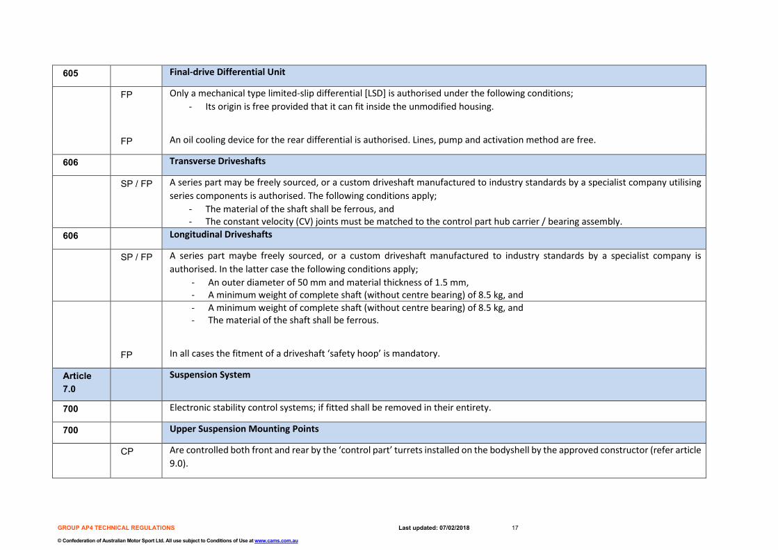
605 Final-drive Differential Unit
FP Only a mechanical type limited-slip differential [LSD] is authorised under the following conditions; - Its origin is free provided that it can fit inside the unmodified housing.
FP An oil cooling device for the rear differential is authorised. Lines, pump and activation method are free.
606 Transverse Driveshafts
SP / FP A series part may be freely sourced, or a custom driveshaft manufactured to industry standards by a specialist company utilising series components is authorised. The following conditions apply;
- The material of the shaft shall be ferrous, and - The constant velocity (CV) joints must be matched to the control part hub carrier / bearing assembly.
606 Longitudinal Driveshafts
SP / FP A series part maybe freely sourced, or a custom driveshaft manufactured to industry standards by a specialist company is authorised. In the latter case the following conditions apply;
- An outer diameter of 50 mm and material thickness of 1.5 mm, - A minimum weight of complete shaft (without centre bearing) of 8.5 kg, and
- A minimum weight of complete shaft (without centre bearing) of 8.5 kg, and - The material of the shaft shall be ferrous.
FP In all cases the fitment of a driveshaft ‘safety hoop’ is mandatory.
Article 7.0
Suspension System
700 Electronic stability control systems; if fitted shall be removed in their entirety.
700 Upper Suspension Mounting Points
CP Are controlled both front and rear by the ‘control part’ turrets installed on the bodyshell by the approved constructor (refer article 9.0).

GROUP AP4 TECHNICAL REGULATIONS Last updated: 07/02/2018 18
© Confederation of Australian Motor Sport Ltd. All use subject to Conditions of Use at www.cams.com.au
700 Front and Rear Upper Plate
FP May be freely sourced provided its sole purpose is to locate and mount the top of the shock absorber (damper) to the bodyshell ‘control part’ turret. The following conditions apply;
- Only aluminium or steel is authorised, - A spherical bearing is permitted’ - The shock absorber shaft (top) shall be located within a maximum of +20mm, in any direction, to the central position of
the turret. 701 Front and Rear Hub Carrier / Bearing Assemblies
CP Are ‘control parts’ and shall be directly fitted to the ‘control part’ upright. The following conditions apply;
CDP - The hub bearing assemblies are series parts, hence direct replacement units of identical specification are authorised.
701 Front and Rear Uprights
CP Are ‘control parts’ and shall not be modified in any way shape or form. They shall be directly fitted to the ‘control part’ wishbones (adapter) and the shock absorber housing. A single upright shall be approved for both Right and Left sides. Each upright unit incorporates the following provisions;
- Attachment point (lower) for the suspension wishbone (adapter). - Attachment point (upper) for the shock absorber unit. - Attachment point for the steering arm (bracket). - Attachment point for the rear toe link. (bracket) - Attachment point for the brake caliper (bracket). - Attachment point for the hub-carrier / bearing assembly.
701 Front and rear lower wishbones
CP These are ‘control parts’ and shall not be modified in any way shape or form. They shall be directly fitted to the ‘control part’ subframes and the ‘control part’ uprights. The following conditions apply;
CDP - The rod end (bearings) may be replaced with direct replacements of the same specification. The only adjustments possible are those provided for by the ‘control parts’.

GROUP AP4 TECHNICAL REGULATIONS Last updated: 07/02/2018 19
© Confederation of Australian Motor Sport Ltd. All use subject to Conditions of Use at www.cams.com.au
701 Front Subframe
CP Shall be directly installed to the mounting points on the bodyshell as fabricated by the approved constructor under the conditions prescribed - refer article 9.0. The following options apply;
- Option 1 Front subframe – for longitudinal engine / gearbox installation [refer control parts list], or - Option 2 Front subframe - for transverse engine / gearbox installation [refer control parts list].
For all options, the following applies; - The front subframe mountings may not be modified and the frame must remain detachable from the bodyshell, and - A minimum weight of 12 kg applies (bare subframe).
701 Rear Subframe
CP Shall be directly installed to the mounting points on the bodyshell as fabricated by the approved constructor under the conditions prescribed - refer article 9.0. The following applies;
- The rear subframe mountings may not be modified and the frame must remain detachable from the bodyshell, and - A minimum weight of 12 kg applies (bare subframe).
707 Front and Rear Shockabsorber/Spring assembly
FP Are free respecting the following conditions; - Only McPherson type shock absorbers / spring assemblies are authorised for the front and rear suspension which must
be of a commercially available mass-produced (ferrous body) type from a recognised suspension components manufacturer,
- Only shock absorber / spring assemblies that fit within the unmodified ‘control part’ bodyshell turret are authorised, and - Only plain bearings are authorised hence linear bearing type dampers are specifically prohibited. - Each assembly part must come from a large scale production catalogue or from a competition parts catalogue.
Article 8.0
Braking Systems
803 FP An alternative hydraulic circuit is authorised to that fitted to the series model, provided the following conditions are respected; - All [brake system] components shall comply with national road transport legalisation / regulations.
ABS systems shall be removed in their entirety.
803 SP / FP Pedal assembly / pressure regulator; either the series parts, or free parts are authorised provided the following conditions are respected;
GROUP AP4 TECHNICAL REGULATIONS Last updated: 07/02/2018 20
© Confederation of Australian Motor Sport Ltd. All use subject to Conditions of Use at www.cams.com.au
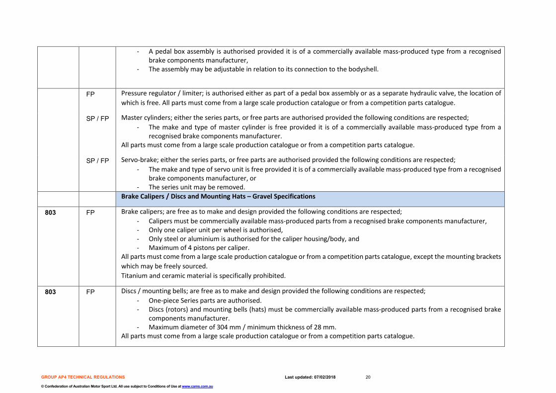
- A pedal box assembly is authorised provided it is of a commercially available mass-produced type from a recognised brake components manufacturer,
- The assembly may be adjustable in relation to its connection to the bodyshell.
FP Pressure regulator / limiter; is authorised either as part of a pedal box assembly or as a separate hydraulic valve, the location of which is free. All parts must come from a large scale production catalogue or from a competition parts catalogue.
SP / FP Master cylinders; either the series parts, or free parts are authorised provided the following conditions are respected; - The make and type of master cylinder is free provided it is of a commercially available mass-produced type from a
recognised brake components manufacturer. All parts must come from a large scale production catalogue or from a competition parts catalogue.
SP / FP Servo-brake; either the series parts, or free parts are authorised provided the following conditions are respected; - The make and type of servo unit is free provided it is of a commercially available mass-produced type from a recognised
brake components manufacturer, or - The series unit may be removed.
Brake Calipers / Discs and Mounting Hats – Gravel Specifications
803 FP Brake calipers; are free as to make and design provided the following conditions are respected; - Calipers must be commercially available mass-produced parts from a recognised brake components manufacturer, - Only one caliper unit per wheel is authorised, - Only steel or aluminium is authorised for the caliper housing/body, and - Maximum of 4 pistons per caliper.
All parts must come from a large scale production catalogue or from a competition parts catalogue, except the mounting brackets which may be freely sourced. Titanium and ceramic material is specifically prohibited.
803 FP Discs / mounting bells; are free as to make and design provided the following conditions are respected; - One-piece Series parts are authorised. - Discs (rotors) and mounting bells (hats) must be commercially available mass-produced parts from a recognised brake
components manufacturer. - Maximum diameter of 304 mm / minimum thickness of 28 mm.
All parts must come from a large scale production catalogue or from a competition parts catalogue.
GROUP AP4 TECHNICAL REGULATIONS Last updated: 07/02/2018 21
© Confederation of Australian Motor Sport Ltd. All use subject to Conditions of Use at www.cams.com.au
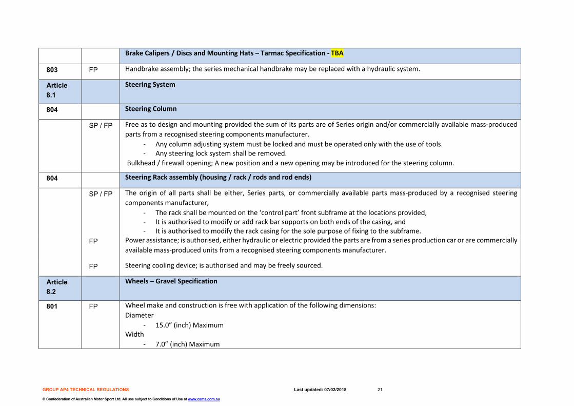
Brake Calipers / Discs and Mounting Hats – Tarmac Specification - TBA
803 FP Handbrake assembly; the series mechanical handbrake may be replaced with a hydraulic system.
Article 8.1
Steering System
804 Steering Column
SP / FP Free as to design and mounting provided the sum of its parts are of Series origin and/or commercially available mass-produced parts from a recognised steering components manufacturer.
- Any column adjusting system must be locked and must be operated only with the use of tools. - Any steering lock system shall be removed.
Bulkhead / firewall opening; A new position and a new opening may be introduced for the steering column.
804 Steering Rack assembly (housing / rack / rods and rod ends)
SP / FP The origin of all parts shall be either, Series parts, or commercially available parts mass-produced by a recognised steering components manufacturer,
- The rack shall be mounted on the ‘control part’ front subframe at the locations provided, - It is authorised to modify or add rack bar supports on both ends of the casing, and - It is authorised to modify the rack casing for the sole purpose of fixing to the subframe.
FP Power assistance; is authorised, either hydraulic or electric provided the parts are from a series production car or are commercially available mass-produced units from a recognised steering components manufacturer.
FP Steering cooling device; is authorised and may be freely sourced.
Article 8.2
Wheels – Gravel Specification
801 FP Wheel make and construction is free with application of the following dimensions: Diameter
- 15.0” (inch) Maximum Width
- 7.0” (inch) Maximum
GROUP AP4 TECHNICAL REGULATIONS Last updated: 07/02/2018 22
© Confederation of Australian Motor Sport Ltd. All use subject to Conditions of Use at www.cams.com.au
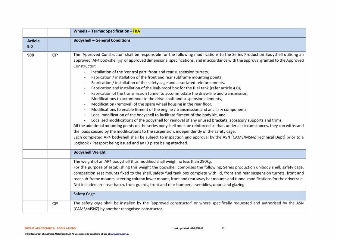
Wheels – Tarmac Specification - TBA
Article 9.0
Bodyshell – General Conditions
900 CP The ‘Approved Constructor’ shall be responsible for the following modifications to the Series Production Bodyshell utilising an approved ‘AP4 bodyshell jig’ or approved dimensional specifications, and in accordance with the approval granted to the Approved Constructor:
- Installation of the ‘control part’ front and rear suspension turrets, - Fabrication / installation of the front and rear subframe mounting points, - Fabrication / installation of the safety cage and associated reinforcements. - Fabrication and installation of the leak-proof box for the fuel tank (refer article 4.0), - Fabrication of the transmission tunnel to accommodate the drive-line and transmission, - Modifications to accommodate the drive-shaft and suspension elements, - Modification (removal) of the spare wheel housing in the rear floor, - Modifications to enable fitment of the engine / transmission and ancillary components, - Local modification of the bodyshell to facilitate fitment of the body kit, and - Localised modifications of the bodyshell for removal of any unused brackets, accessory supports and trims.
All the additional mounting points on the series bodyshell must be reinforced so that, under all circumstances, they can withstand the loads caused by the modifications to the suspension, independently of the safety cage. Each completed AP4 bodyshell shall be subject to inspection and approval by the ASN [CAMS/MSNZ Technical Dept] prior to a Logbook / Passport being issued and an ID plate being attached.
Bodyshell Weight
The weight of an AP4 bodyshell thus modified shall weigh no less than 290kg. For the purpose of establishing this weight the bodyshell comprises the following; Series production unibody shell, safety cage, competition seat mounts fixed to the shell, safety fuel tank box complete with lid, front and rear suspension turrets, front and rear sub-frame mounts, steering column lower mount, front and rear sway bar mounts and tunnel modifications for the drivetrain. Not included are: rear hatch, front guards, front and rear bumper assemblies, doors and glazing.
Safety Cage
CP The safety cage shall be installed by the ‘approved constructor’ or where specifically requested and authorised by the ASN [CAMS/MSNZ] by another recognised constructor.
GROUP AP4 TECHNICAL REGULATIONS Last updated: 07/02/2018 23
© Confederation of Australian Motor Sport Ltd. All use subject to Conditions of Use at www.cams.com.au
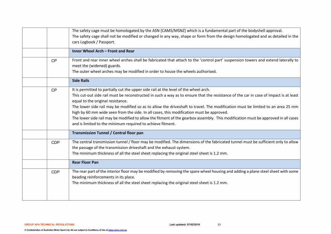
The safety cage must be homologated by the ASN [CAMS/MSNZ] which is a fundamental part of the bodyshell approval. The safety cage shall not be modified or changed in any way, shape or form from the design homologated and as detailed in the cars Logbook / Passport.
Inner Wheel Arch – Front and Rear
CP Front and rear inner wheel arches shall be fabricated that attach to the ‘control part’ suspension towers and extend laterally to meet the (widened) guards. The outer wheel arches may be modified in order to house the wheels authorised.
Side Rails
CP It is permitted to partially cut the upper side rail at the level of the wheel arch. This cut-out side rail must be reconstructed in such a way as to ensure that the resistance of the car in case of impact is at least equal to the original resistance. The lower side rail may be modified so as to allow the driveshaft to travel. The modification must be limited to an area 25 mm high by 60 mm wide seen from the side. In all cases, this modification must be approved. The lower side rail may be modified to allow the fitment of the gearbox assembly. This modification must be approved in all cases and is limited to the minimum required to achieve fitment.
Transmission Tunnel / Central floor pan
CDP The central transmission tunnel / floor may be modified. The dimensions of the fabricated tunnel must be sufficient only to allow the passage of the transmission driveshaft and the exhaust system. The minimum thickness of all the steel sheet replacing the original steel sheet is 1.2 mm.
Rear Floor Pan
CDP The rear part of the interior floor may be modified by removing the spare wheel housing and adding a plane steel sheet with some beading reinforcements in its place. The minimum thickness of all the steel sheet replacing the original steel sheet is 1.2 mm.

GROUP AP4 TECHNICAL REGULATIONS Last updated: 07/02/2018 24
© Confederation of Australian Motor Sport Ltd. All use subject to Conditions of Use at www.cams.com.au
Front Cross-Member (radiator support)
SP / FP The upper and/or lower front cross-member may be modified (between the headlamps of the car) to enable fitment of the engine / engine ancillaries provided this does not affect the rigidity of the chassis structure. Additionally, the cross-member may be replaced with a different support.
Jacking / Stand Support Points
FP Jacking points may be added, strengthened and/or moved in the bodyshell sill panels.
Article 9.1
Bodyshell External Panels
Doors
SP The series rear doors may be modified, solely for the following reasons; - Localised modification of the rear doors is authorised to allow the passage of the wheel, or the addition of an extended
wheel arch flare. CDP Lateral Side Protection; Energy Absorbing Safety Foam (NOTE: Mandatory for each CAMS Approved AP4 Vehicle)
Energy Absorbing Safety Foam shall be fitted in accordance with CAMS National Rally Code Appendix F including the requirement for door panels. Polycarbonate side windows are permitted in accordance with the requirements for the fitment of this foam.
Body Kit
CDP A body-kit shall be created / obtained, the design of which must be approved by the ASN [CAMS/MSNZ]. The body-kit shall comprise of the following parts which shall be shown ( 3/4 front and 3/4 rear photos) in the cars Logbook / Passport;
- Front bumper - Rear bumper - Front guards (LH and RH) - Rear guards (LH and RH) including rear door extensions - Side skirts - Rear aerodynamic device (rear spoiler / wing assembly)
Front Bumper
CDP The basic shape of the series front bumper (central section) must be retained, although the following is authorised;

GROUP AP4 TECHNICAL REGULATIONS Last updated: 07/02/2018 25
© Confederation of Australian Motor Sport Ltd. All use subject to Conditions of Use at www.cams.com.au
- The bumper may be widened in order to align with widening of the front guards, - The series grille may be replaced with wire mesh, - Additional openings may be made in the bumper together with the side elements of the front wings, but the total
surface of openings in the protective moulding must be no more than 2500 cm2. The openings must not affect the structural integrity of the bumper,
- The material shall be that of the series part and/or fibreglass, - The minimum weight of the front bumper is 4.5 kg (except if the original bumper is kept), - The lower part of the front bumper may be detachable. No element of this detachable part may be more than 100 mm
in height and protrude beyond the upper part, when seen in vertical projection, and - New fastenings may be created to enable ease of removal / replacement. - It is permitted to remove the original mounting / crash protection parts situated between the series bumper and the
bodyshell. Rear Bumper
CDP The basic shape of the series rear bumper (central section) must be retained, although the following is authorised; - The bumper may be widened in order to align with widening of the rear guards, - The material shall be that of the series part and/or fibreglass, - Replacement of series removable decorative features with a flat surface forming an integral part of the rear bumper, - A modification of the original cut-out for the exhaust, or to create a 100 cm2 cut-out, is authorised, and - New fastenings may be created to enable ease of removal / replacement. - It is permitted to remove the original mounting / crash protection parts situated between the series bumper and the
bodyshell. Front Guards
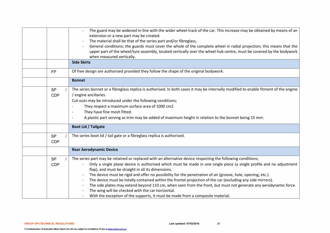
CDP The basic shape of the front guards (upper section) must be retained, although the following is authorised; - The guard may be widened in-line with the wider wheel-track of the car. This increase may be obtained by means of an
extension or a new part may be created. - The material shall be that of the series part and/or fibreglass, - The maximum width between the guards is 1820 mm (measured on the front axle centre-line), - No additional air intakes or outlets are authorised, and - Additional aerodynamic elements are not authorised.
Rear Guards
CDP The basic shape of the rear guards (upper section) must be retained, although the following is authorised;
GROUP AP4 TECHNICAL REGULATIONS Last updated: 07/02/2018 26
© Confederation of Australian Motor Sport Ltd. All use subject to Conditions of Use at www.cams.com.au
- The guard may be widened in-line with the wider wheel-track of the car. This increase may be obtained by means of an extension or a new part may be created.
- The material shall be that of the series part and/or fibreglass, - General conditions; the guards must cover the whole of the complete wheel in radial projection; this means that the
upper part of the wheel/tyre assembly, located vertically over the wheel hub centre, must be covered by the bodywork when measured vertically.
Side Skirts
FP Of free design are authorised provided they follow the shape of the original bodywork.
Bonnet
SP / CDP
The series bonnet or a fibreglass replica is authorised. In both cases it may be internally modified to enable fitment of the engine / engine ancillaries. Cut-outs may be introduced under the following conditions; - They respect a maximum surface area of 1000 cm2 - They have fine mesh fitted. - A plastic part serving as trim may be added of maximum height in relation to the bonnet being 15 mm.
Boot Lid / Tailgate
SP / CDP
The series boot lid / tail gate or a fibreglass replica is authorised.
Rear Aerodynamic Device
SP / CDP
The series part may be retained or replaced with an alternative device respecting the following conditions; - Only a single plane device is authorised which must be made in one single piece (a single profile and no adjustment
flap), and must be straight in all its dimensions. - The device must be rigid and offer no possibility for the penetration of air (groove, hole, opening, etc.). - The device must be totally contained within the frontal projection of the car (excluding any side mirrors). - The side plates may extend beyond 110 cm, when seen from the front, but must not generate any aerodynamic force. - The wing will be checked with the car horizontal. - With the exception of the supports, it must be made from a composite material.
GROUP AP4 TECHNICAL REGULATIONS Last updated: 07/02/2018 27
© Confederation of Australian Motor Sport Ltd. All use subject to Conditions of Use at www.cams.com.au
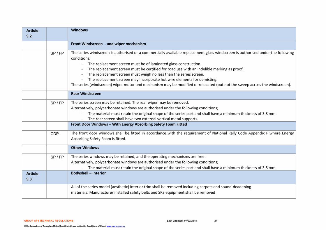
Article 9.2
Windows
Front Windscreen - and wiper mechanism
SP / FP The series windscreen is authorised or a commercially available replacement glass windscreen is authorised under the following conditions;
- The replacement screen must be of laminated glass construction. - The replacement screen must be certified for road use with an indelible marking as proof. - The replacement screen must weigh no less than the series screen. - The replacement screen may incorporate hot wire elements for demisting.
The series (windscreen) wiper motor and mechanism may be modified or relocated (but not the sweep across the windscreen).
Rear Windscreen
SP / FP The series screen may be retained. The rear wiper may be removed. Alternatively, polycarbonate windows are authorised under the following conditions;
- The material must retain the original shape of the series part and shall have a minimum thickness of 3.8 mm. - The rear screen shall have two external vertical metal supports.
Front Door Windows – With Energy Absorbing Safety Foam Fitted
CDP The front door windows shall be fitted in accordance with the requirement of National Rally Code Appendix F where Energy Absorbing Safety Foam is fitted.
Other Windows
SP / FP The series windows may be retained, and the operating mechanisms are free. Alternatively, polycarbonate windows are authorised under the following conditions;
- The material must retain the original shape of the series part and shall have a minimum thickness of 3.8 mm. Article 9.3
Bodyshell – Interior
All of the series model (aesthetic) interior trim shall be removed including carpets and sound-deadening materials. Manufacturer installed safety belts and SRS equipment shall be removed

GROUP AP4 TECHNICAL REGULATIONS Last updated: 07/02/2018 28
© Confederation of Australian Motor Sport Ltd. All use subject to Conditions of Use at www.cams.com.au
Front and Rear Bulkheads
FP For 2 and 3 volume cars the front bulkhead must provide an air-tight and fluid-tight seal between the engine and interior. For 3 volume cars, additionally a rear (boot compartment) bulkhead may be fitted.
Dashboard / Instruments
SP The series dashboard may be modified or replaced with a dashboard of an alternate material although the general shape and appearance of the original must be retained. The anchorage points may be modified / added to for the sole purpose of installing the safety cage. The trim situated below the dashboard and which is not a part of it may be removed.
SP / FP The series instruments are authorised, or instruments may be freely sourced provided compliance is maintained with that as required by local authorities. (i.e. Registration or Warrant of Fitness etc.)
FP Supplementary panels for instruments and/or switches are authorised.
Heating / Air-conditioning
SP / FP The series heating / AC system may be removed in which case an electric demist system or similar system must be retained, to ensure that an effective method of demisting the windscreen is maintained.
Article 9.4
Underbody protection / Mud-Flaps
FP The fitting of underbody protections is authorised under the following conditions; - They are made from an authorised material; Kevlar, Aluminium, steel or plastic. - They are designed to be removable. - They are designed exclusively and specifically to protect the following parts; Engine, Radiator, Suspension, Gearbox,
Transmission, Fuel tank, Steering, Exhaust and Extinguishers. FP Transverse mud-flaps shall be fitted to the bodywork that cover the whole width / height of each tyre [when viewed from the rear
of the vehicle] and have a ground clearance between 50 mm and 100 mm [when the vehicle is stationary]. The material shall be flexible and have a minimum thickness of 4.0 mm.

GROUP AP4 TECHNICAL REGULATIONS Last updated: 07/02/2018 29
© Confederation of Australian Motor Sport Ltd. All use subject to Conditions of Use at www.cams.com.au
3. PART 3 - APPROVED CONSTRUCTORS AND CONTROL PARTS LIST
LIST 1 – APPROVED CONSTRUCTORS / COMPANIES - The following companies are authorised to perform the bodyshell modifications as prescribed in PART TWO Article 9.0 of these regulations; - For the avoidance of any doubt, an ‘Approved Constructor’ is a company or individual who are authorised by the ASN being either MotorSport New
Zealand or CAMS and are detailed below; - Expressions of interest to become an ‘Approved Constructor’ should be directed to the ASN of the country in which the applicant operates.
Constructor / Company Location Physical Address Contact information
Force Motorsport Limited Auckland - New Zealand Force Motorsport Ltd 21 Brookby Road, RD1 Manurewa, Auckland 2576 New Zealand
Andrew Hawkeswood – +64 (0)21 784 675
Race Torque Engineering NOTE: MAXI Car agent; and AP4 Constructor
Perth - Australia Race Torque Engineering Pty Ltd 16 Action Place Wangara, Perth 6065 Australia
Lane Heenan - +61 8 930 26388
Team Ralliart NZ Pukekohe – New Zealand Team Ralliart NZ Unit 3/17 Sweetcorn Place Pukekohe 2120 New Zealand
Chris (Choice) Little - +64 (0)21 928 692 Bill Morton - +64 (0)9 238 5359
Emma Gilmour Promotions Ltd Dunedin – New Zealand TBA Emma Gilmour - +64 (0)21 520 122 MPart AB Orebro - Sweden MPart AB
Berglundavagen 3B OREBRO, Sweden
Tomas Weng - [email protected]
Neal Bates Motorsport Canberra - Australia Neal Bates Motorsport 48 Sheppard Street Hume ACT 2620 Australia
Darryl Bush – +61 (0) 2 6201536 [email protected]
GROUP AP4 TECHNICAL REGULATIONS Last updated: 07/02/2018 30
© Confederation of Australian Motor Sport Ltd. All use subject to Conditions of Use at www.cams.com.au
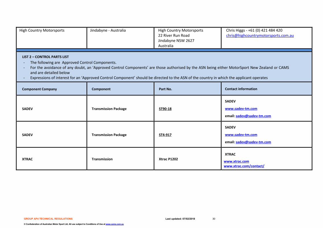
High Country Motorsports Jindabyne - Australia High Country Motorsports 22 River Run Road Jindabyne NSW 2627 Australia
Chris Higgs - +61 (0) 421 484 420 [email protected]
LIST 2 – CONTROL PARTS LIST - The following are Approved Control Components. - For the avoidance of any doubt, an ‘Approved Control Components’ are those authorised by the ASN being either MotorSport New Zealand or CAMS
and are detailed below - Expressions of interest for an ‘Approved Control Component’ should be directed to the ASN of the country in which the applicant operates
Component Company Component Part No. Contact information
SADEV Transmission Package ST90-18
SADEV
www.sadev-tm.com
email: [email protected]
SADEV Transmission Package ST4-917
SADEV
www.sadev-tm.com
email: [email protected]
XTRAC Transmission Xtrac P1202 XTRAC
www.xtrac.com www.xtrac.com/contact/