€¦ · · 2018-04-04author: s. breuer editors: h.-j. drung, m. holder layout: festo ag &...
TRANSCRIPT

Positioning system
Smart Positioning ControllerSPC200

Author: S. BreuerEditors: H.-J. Drung, M. HolderLayout: Festo AG & Co., Dept. KI-TDTypesetting: KI-TD
Edition: 9904a
© (Festo AG & Co., D-73726 Esslingen, Federal Republic of Germany, 1999)
The copying, distribution and utilization of this docu-ment as well as the communication of its contents toothers without expressed authorization is prohibited. Offenders will be held liable for the payment of dam-ages. All rights reserved, in particular the right to carryout patent, utility model or ornamental design registra-tions. P
rinte
d on
100
% r
ecyc
led
pape
r
SPC200... 9904a I
IBM® Registered trademark ofInternational BusinessMachines Corporation
Microsoft® Registered trade mark of theWindows® Microsoft Corporation
Temposonics® Registered trade mark ofMTS Sensortechnologie GmbH & Co
Order No.: 170 246Title: ManualReference: P.BE-SPC200-GB
II SPC200... 9904a

Contents
Designated use............................................................................................ VITarget group .............................................................................................. VIIImportant user instructions ........................................................................ VIIAbout this manual........................................................................................ IXProduct-specific terms and abbreviations .................................................. XI
1. System summary
1.1 Positioning systems with the SPC200 ...........................................1-41.1.1 The range of equipment for the SPC200.......................................1-71.1.2 Structure of the SPC200 ................................................................1-91.2 Connecting pneumatic axes.........................................................1-131.3 Structure of the axis interface string ............................................1-171.4 Operating modes of the SPC200.................................................1-211.5 Multi-axis applications with the SPC200......................................1-231.6 Commissioning and programming options...................................1-241.7 I/O address range of the SPC200 ...............................................1-28
2. Fitting
2.1 Inserting and removing modules ....................................................2-52.2 Mounting the basic unit ..................................................................2-92.3 Fitting the control panel................................................................2-122.4 Fitting the axis interface and I/O function module .......................2-142.5 Instructions on fitting the pneumatic axis.....................................2-19
3. Installation
3.1 General instructions on installation ................................................3-43.2 Instructions on pneumatic installation ............................................3-53.2.1 Pneumatic emergency stop circuit ...............................................3-153.2.2 Tubing for slide and yoke operation.............................................3-193.3 Installing the SPC200...................................................................3-213.3.1 Selecting the power unit...............................................................3-223.3.2 Connections of the power supply module....................................3-243.3.3 Connections of the diagnostic module.........................................3-303.3.4 Connections of I/O module SPC200-DIO-... ................................3-333.3.5 Connections of analogue input module type SPC200-2AI-U ......3-42
SPC200... 9904a III
3.3.6 Connections on the subcontroller module typeSPC200-SCU-AIF........................................................................ 3-45
3.4 Installing the modules on the axis interface string...................... 3-473.4.1 Installing the axis interface SPC-AIF-... ...................................... 3-513.4.2 Installing I/O function module SPC-FIO-2E/2A-M8 ..................... 3-56
4. Commissioning
4.1 Procedure for commissioning........................................................ 4-54.2 Connecting a single axis system for initial commissioning ........... 4-94.3 Commissioning via the control panel .......................................... 4-164.3.1 Saving the hardware configuration.............................................. 4-164.3.2 Commissioning pneumatic axes.................................................. 4-204.3.3 Instructions on commissioning multi-axis systems...................... 4-38
5. Controlling the SPC200
5.1 General instrutions on operation ................................................... 5-45.2 Start/stop mode ............................................................................. 5-95.2.1 Explanation of all I/O signals in start/stop mode......................... 5-115.3 Record select mode..................................................................... 5-175.3.1 Description of all I/O signals in record select mode ................... 5-22
6. Operation of the SPC200 via thecontrol panel
6.1 Layout and functions of the control panel ..................................... 6-46.1.1 Moving around the menu system.................................................. 6-86.2. Setting project-specific parameters ............................................. 6-146.3 Editing programs.......................................................................... 6-286.3.1 Adding a new program ................................................................ 6-296.3.2 Editing instructions....................................................................... 6-356.3.3 Instruction set on the control panel ............................................. 6-376.3.4 Editing an existing program......................................................... 6-406.3.5 Deleting a program...................................................................... 6-426.4 Editing the position register ......................................................... 6-436.5 Controlling the program run......................................................... 6-476.6 Display of operands and system states ...................................... 6-496.7 Setting the closed loop control factors ........................................ 6-516.8 Test and diagnostic functions of the control panel ..................... 6-53
IV SPC200... 9904a

7. Description of the commands
7.1 General notes on programming .....................................................7-47.1.1 Coordinated and autonomous mode..............................................7-57.2 Notes on programming via the control panel.................................7-87.2.1 Explanation of the NC commands on the control panel ..............7-13
8. Diagnosis and error treatment
8.1 On-the-spot dagnosis .....................................................................8-48.2 Error messages on the control panel.............................................8-98.3 Eliminating errors on the system..................................................8-248.3.1 Errors when the system is switched on .......................................8-248.3.2 Errors in positioning......................................................................8-25
A. Optimizing the positioning behaviour
A.1 Basic information on control.......................................................... A-3A.2 Description of the controller factors .............................................. A-6A.3 Optimizing the positioning behaviour ............................................ A-9A.3.1 How to deal with an instable compressed air supply ................. A-15
B. Technical appendix
B.1 Internal structure of the inputs and outputs .................................. B-3B.2 Technical specifications................................................................. B-7B.2.1 Technical specifications of the SPC200........................................ B-7B.2.2 Technical specifications of axis interface type SPC-AIF-... ........ B-13B.2.3 Technical specifications of I/O function module
type SPC-FIO-............................................................................. B-14B.2.4 Technical specifications of control panel type SPC200-MMI-1 .. B-15
C. Index
C.1 Index..............................................................................................C-3
SPC200... 9904a V

Designated use
The SPC200 Smart Positioning Controller is designedfor fitting into a control cabinet. It serves as a position-ing controller and closed loop controller for pneumaticaxes, as well as a positioning controller for steppingmotor axes. Basic modules and modules for theSPC200 are described in this manual. Special exten-sion modules are described in separate manuals.
The safety instructions must be observed at all timesand the various components and modules must beused as intended. Please observe also the safety in-structions listed in the operating instructions for thepneumatic and electrical components used.
The SPC200 and the associated modules and cableare only to be used as follows:
– as designated
– in original condition
– without unauthorised modifications
– in faultless technical condition.
The specified limit values for pressures, temperatures,electrical data, torques, etc., must be observed whenadditional commercially-available components such assensors and actuators are connected. Please complyalso with national and local safety laws and regulations.
VI SPC200... 9904a
Target group
This manual is directed exclusively at technicians whoare trained in control and automation technology andwho have experience in installing, commissioning, pro-gramming and diagnosing positioning systems.
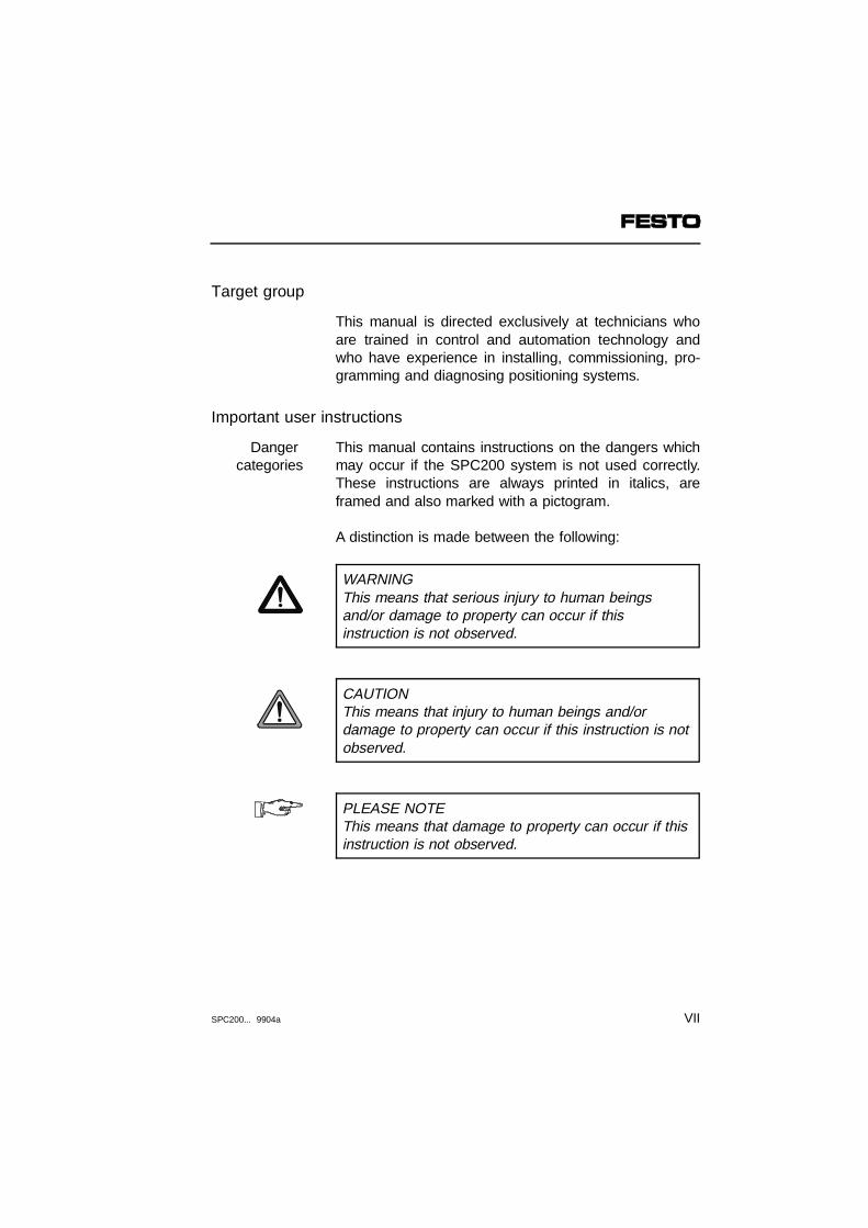
Important user instructions
This manual contains instructions on the dangers whichmay occur if the SPC200 system is not used correctly.These instructions are always printed in italics, areframed and also marked with a pictogram.
Danger categories
A distinction is made between the following:
WARNINGThis means that serious injury to human beingsand/or damage to property can occur if thisinstruction is not observed.
CAUTIONThis means that injury to human beings and/ordamage to property can occur if this instruction is notobserved.
PLEASE NOTEThis means that damage to property can occur if thisinstruction is not observed.
SPC200... 9904a VII
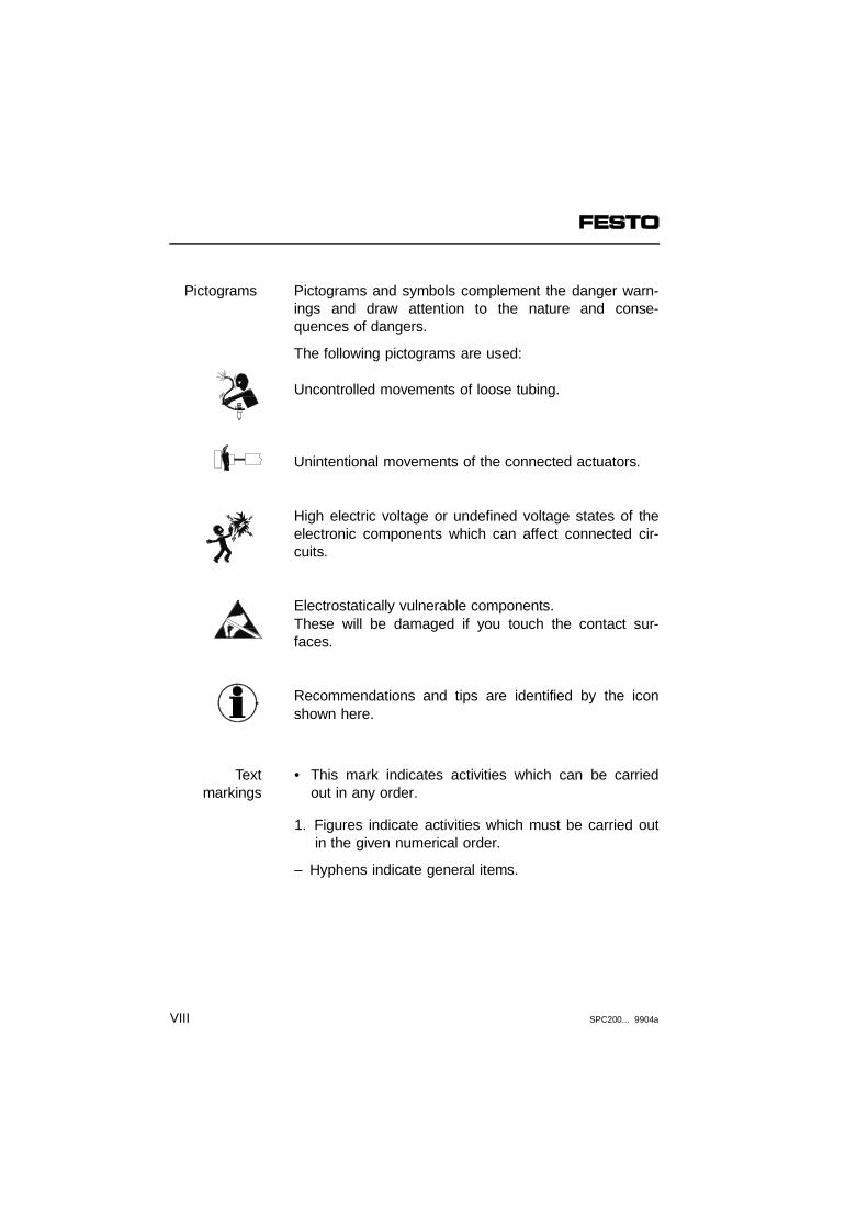
Pictograms and symbols complement the danger warn-ings and draw attention to the nature and conse-quences of dangers.
Pictograms
The following pictograms are used:
Uncontrolled movements of loose tubing.
Unintentional movements of the connected actuators.
High electric voltage or undefined voltage states of theelectronic components which can affect connected cir-cuits.
Electrostatically vulnerable components.These will be damaged if you touch the contact sur-faces.
Recommendations and tips are identified by the iconshown here.
• This mark indicates activities which can be carriedout in any order.
Text markings
1. Figures indicate activities which must be carried outin the given numerical order.
– Hyphens indicate general items.
VIII SPC200... 9904a

About this manual
This manual contains general, fundamental informationon the functions, assembly, installation andcommissioning of pneumatic axes in conjunction withthe SPC200. This manual refers to the Smart Position-ing Controller SPC200 with operating system versionV 3.x.
Particular information relating to the commissioning,programming and diagnosis of the SPC200 using theWinPISA software is to be found in the WinPISAmanual.
Information on the pneumatic components will be foundin the Operating Instructions accompanying the product.The following table provides an overview.
SPC200... 9904a IX
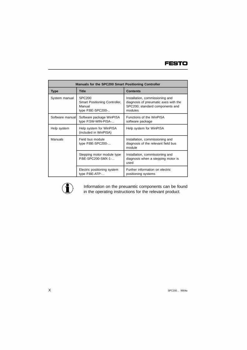
Manuals for the SPC200 Smart Positioning Controller
Type Title Contents
System manual SPC200 Smart Positioning Controller,Manual type P.BE-SPC200-..
Installation, commissioning and diagnosis of pneumatic axes with theSPC200; standard components and modules
Software manual Software package WinPISAtype P.SW-WIN-PISA-...
Functions of the WinPISA software package
Help system Help system for WinPISA (included in WinPISA)
Help system for WinPISA
Manuals Field bus module type P.BE-SPC200-...
Installation, commissioning and diagnosis of the relevant field bus module
Stepping motor module typeP.BE-SPC200-SMX-1-...
Installation, commissioning and diagnosis when a stepping motor isused
Electric positioning systemtype P.BE-ATP-...
Further information on electric positioning systems
Information on the pneuamtic components can be foundin the operating instructions for the relevant product.
X SPC200... 9904a

Product-specific terms and abbreviations
The following product-specific terms and abbreviationsare used in this manual:
Term/Abbreviation
Meaning
0-signal 0 V input or output signals
1-signal 24 V input or output signals
Axis data Configuration information, describing the structure, properties andcomponents of the axis used.
Axis interface The measuring system and the proportional directional control valveare connected to the SPC200 via the axis interface.
Axis interfacestring
The totality of the modules, connected in common to the axis interfaceconnection of the SPC200
Application data Configuration information, describing the conditions of use determinedby the application.
CP cable Special cable for connecting the various CP modules
F Flag
I Digital input
I/O module Common term for the CP modules, which provide digital inputs and outputs
I/Os Digital inputs and outputs
Modules Plug-in cards, which can be inserted into the SPC200 rack or field device and which can be connected to the axis interface string.
PLC/IPC Programmable logic controller/PC
Q Digital output
R Register
String The total number of modules connected together on the axis interfacestring.
SPC200... 9904a XI

XII SPC200... 9904a

Chapter 1
System summary
1. System summary
SPC200... 9904a 1-1
Contents
1. System summary
1.1 Positioning systems with the SPC200........................................... 1-41.1.1 The range of equipment for the SPC200...................................... 1-71.1.2 Structure of the SPC200 ............................................................... 1-91.2 Connecting pneumatic axes ........................................................ 1-131.3 Structure of the axis interface string ........................................... 1-171.4 Operating modes of the SPC200 ................................................ 1-211.5 Multi-axis applications with the SPC200 ..................................... 1-231.6 Commissioning and programming options .................................. 1-241.7 I/O address range of the SPC200............................................... 1-28
1. System summary
1-2 SPC200... 9904a
This chapter gives a summary of the possibilities of ex-tending positioning systems with the SPC200; it de-scribes the devices which can be used with theSPC200 as well as the structure of the SPC200. Thischapter also contains basic information on:
Contents ofthis chapter
– connecting pneumatic axes to the axis interfacestring
– the operating modes, commissioning and program-ming possibilities of the SPC200
– the address range of the SPC200.
Coupling to field bus systems is made possible byspecial field bus modules. Detailed information on thesecan be found in the manual for the relevant field busmodule.
Furtherinformation
Electric axes can be connected by means of specialmodules. Detailed information on these can be found inthe manual for the relevant module.
1. System summary
SPC200... 9904a 1-3
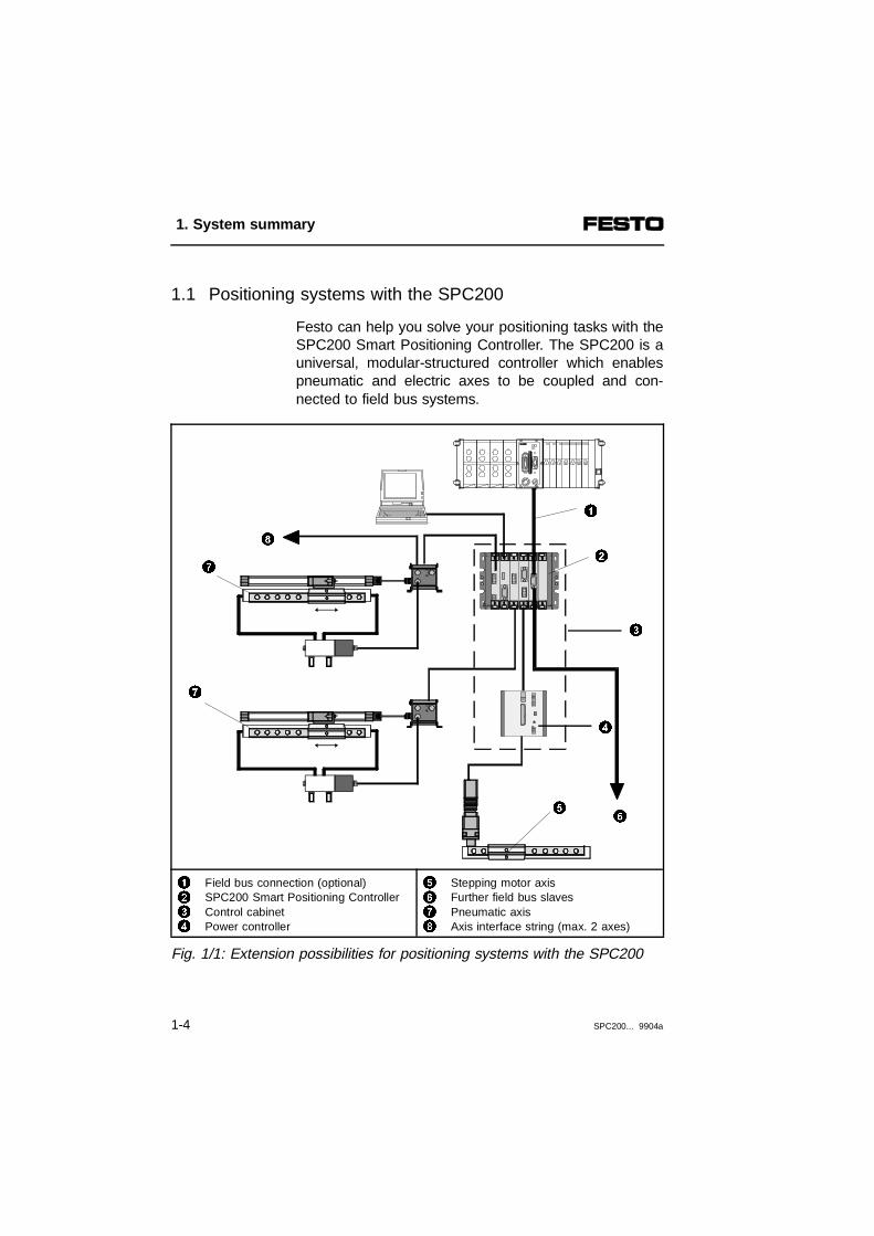
1.1 Positioning systems with the SPC200
Festo can help you solve your positioning tasks with theSPC200 Smart Positioning Controller. The SPC200 is auniversal, modular-structured controller which enablespneumatic and electric axes to be coupled and con-nected to field bus systems.
1234
Field bus connection (optional)SPC200 Smart Positioning ControllerControl cabinetPower controller
5678
Stepping motor axisFurther field bus slavesPneumatic axisAxis interface string (max. 2 axes)
Fig. 1/1: Extension possibilities for positioning systems with the SPC200
7
2
1
8
7
3
56
4
1. System summary
1-4 SPC200... 9904a

Depending on the equipment fitted on the controller, upto four axes can be coupled. Pneumatic and electricaxes can be operated together. The components of thepneumatic axes as well as external I/O modules, whereapplicable, are connected to the SPC200 via maximumtwo axis interface strings each with one cable.
12
First axis interface stringSecond axis interface string (optional)
34
Axis interfaceExternal I/O modules
Fig. 1/2: Connecting pneumatic axes and external I/O modules
1
2
3
4
33
1. System summary
SPC200... 9904a 1-5
The SPC200 can be operated either independently orin conjunction with a higher-order PLC/IPC. To a limitedextent, it can also perform control functions. For thispurpose, I/O modules with digital inputs/outputs can beintegrated in the SPC200 or external I/O modules canbe connected to the axis interface string.
Coupling to a higher-order PLC/IPC can be made viadigital inputs/outputs or via special field bus moduleswith integrated field bus interface (e.g. Interbus;PROFIBUS-DP etc.).
1. System summary
1-6 SPC200... 9904a

1.1.1 The range of equipment for the SPC200
The range of equipment for the SPC 200 includes thefollowing components:
Components Function
SPC200type SPC200-...-...
The SPC200 is accomodated in a rack.Appropriate modules can be installed inthe rack according to the requirementsof the positioning task.
Control paneltype SPC200-MMI-1
The control panel can be pluggeddirectly into the SPC200. All functions can be operated through amenu interface using the 6 keys on thepanel.
Axis interfacetype SPC-AIF-...
The axis interface forms the connectionbetween the components on thepneumatic axis and the SPC200. It receives the values issued by themeasuring system, passes them to theSPC200 and supplies the signal forsetting the proportional directionalcontrol valve.
I/O function module(optional) type SPC-FIO-2E/2A-M8
Provides two inputs and two outputs onthe axis allowing direct connection ofsensors and actuators. Additional functions e.g. gripping, lifting,lowering and turning can beimplemented with these sensors andactuatrs.
1. System summary
SPC200... 9904a 1-7

If required, the following CP I/O modules and CPVvalve terminals can be connected to the end of the axisinterface string.
CP module(optional)
Function
CPV valveterminals type CPV...-...-...
Provides various valve functions for controllingpneumatic actuators by means of valve plates.Relay plates, pressure isolating plates andblanking plates can be integrated.
I modules type CP-E16...-M...
There are special designs for variousconecting variants. These provide inputs forconnecting sensors and enable e.g. cylinderpositions to be interrogated.
O modules typeCP-A08-M12
These provide universally usuable electricaloutputs for controlling low-current consumingdevices (valves, lights etc.).
1. System summary
1-8 SPC200... 9904a

1.1.2 Structure of the SPC200
The SPC200 is modular-structured and is accomodatedin a rack. The main processor and memory of theSPC200 are on the rear printed circuit board in therack.
The combination of rack and rear printed circuit boardis called the basic unit. Basic units with 4 and 6 slotsare available for you to implement various extensionvariants.
12
Rack (basic unit)Modules
3 Rear pinted circuit board(in the rack)
Fig. 1/3: The SPC200 Smart Positioning Controller
Appropriate modules can be installed in the basic unitaccording to the requirements of the positioning task.
2
3
1
1. System summary
SPC200... 9904a 1-9

With just the following modules, the SPC200 provides afunctioning controller for pneumatic axes.
Basicmodules
123
Supply module type SPC200-PWR-AIFDiagnostic module type SPC200-MMI-DIAGI/O module type SPC200-DIO
Fig. 1/4: Basic modules of the SPC200
Module Description
Supply module Enables the power supply and the axisinterface designed as a field device to beconnected.
Diagnosticmodule
Enables the control panel to be inserted anda PC to be connected.
I/O module Provides the I/Os necessary for controlling inthe various operating modes.
2 31
1. System summary
1-10 SPC200... 9904a
A system with the components shown above offers thefollowing scope of performance:
– up to two pneumatic axes can be controlled
– various types of measuring systems can be con-nected by means of different variants of the axis in-terface
– independent operation or coordination with an exter-nal PLC/IPC via I/Os
– programming and operation via a PC or a controlpanel.
The modules listed in the following table can be usedfor extending the system:
Extensionmodules
1. System summary
SPC200... 9904a 1-11
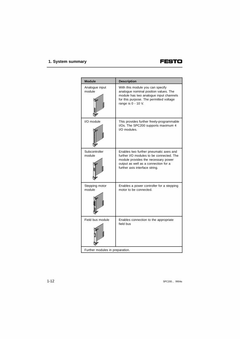
Module Description
Analogue input module
With this module you can specifyanalogue nominal position values. Themodule has two analogue input channelsfor this purpose. The permitted voltagerange is 0 - 10 V.
I/O module This provides further freely-programmableI/Os. The SPC200 supports maximum 4I/O modules.
Subcontrollermodule
Enables two further pneumatic axes andfurther I/O modules to be connected. Themodule provides the necessary poweroutput as well as a connection for afurther axis interface string.
Stepping motormodule
Enables a power controller for a steppingmotor to be connected.
Field bus module Enables connection to the appropriatefield bus
Further modules in preparation.
1. System summary
1-12 SPC200... 9904a

1.2 Connecting pneumatic axes
The SPC200 controls the pneumatic axes and regu-lates their position. The measuring system and the pro-portional directional control valve are connected via theaxis interface which is placed directly on the drive.
The axis interface is connected to the SPC200 via onlyone cable, the axis interface string. The following diag-ram shows the basic structure of a pneumatic axis withthe SPC200.
123
Measuring systemAxis interface type SPC-AIF-...SPC200 Smart Positioning Controller
4
56
Proportional directional control valvetype MPYE-...Service unit with 5 µm filterCylinder
Fig. 1/5: Connecting pneumatic axes to the SPC200
2
3
4
5
6
1
1. System summary
SPC200... 9904a 1-13
In order to install a pneumatic axis you will require thefollowing components:
Components
– the SPC200 axis controller
– an axis interface type SPC-AIF-....
– a proportional directional control valve type MPYE-5-...-010B
– a measuring system type MLO-POT-...-TLF or typeMME-MTS-...-TLF-AIF(with cylinder type DGPI(L)-...-...-...-AIF this meas-uring system is integrated)
– a cylinder with mechanical guidance
– a service unit with 5 µm filter
– a 24 V power supply
– optional components for pneumatic emergency shut-down
The SPC200 Smart Positioning Controller takes overprincipally the following tasks:
– specifying the reference positions by position control
– comparing the reference and actual positions and po-sition control by appropriate control of the proportio-nal directional control valve (status control)
– optimizing control by parameter modification
– controlling peripherals using digital inputs and out-puts and sequence control.
1. System summary
1-14 SPC200... 9904a

Method of operation
The diagram below shows the method of operation of apositioning control circuit using an SPC200 Smart Posi-tioning Controller.
123
Cylinder position = control valueActual position (actual value)Valve voltage (setting signal)
45
Axis interface stringPositioning control/SPC200 controller
Fig. 1/6: Position control circuit with pneumatic components
The axis interface, valve, cylinder and measuring sys-tem are connected together in such a way that theyform a closed-loop control circuit. The position of theslide or the piston represents the control value in thiscontrol circuit. This control is therefore also referred toas a positioning control.
3
5
4
1
2
1. System summary
SPC200... 9904a 1-15

In the following the terms piston and slide are equival-ent in meaning.
The measuring system constantly records the positionof the slide and passes this to the axis interface as anelectrical signal.
The measured values are passed from the axis inter-face to the SPC200 Smart Positioning Controller. Thiscompares the reference position with the actual positionand calculates therefrom the positioning signal for theproportional directional control valve.
The proportional directional control valve controls theslide by pressurizing one of the cylinder chambers andexhausting the other. In the mid-position the flow isblocked so that the slide typically remains at the currentposition.
1. System summary
1-16 SPC200... 9904a
1.3 Structure of the axis interface string
The SPC200 is intended for fitting into a controlcabinet. Connection to the measuring system and tothe proportional directional control valve is made via theaxis interface which is connected to the SPC200 via theaxis interface string.
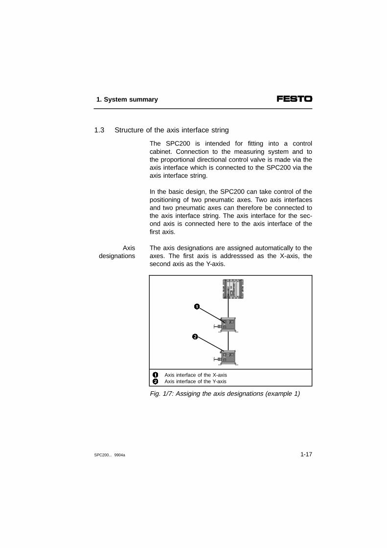
In the basic design, the SPC200 can take control of thepositioning of two pneumatic axes. Two axis interfacesand two pneumatic axes can therefore be connected tothe axis interface string. The axis interface for the sec-ond axis is connected here to the axis interface of thefirst axis.
The axis designations are assigned automatically to theaxes. The first axis is addresssed as the X-axis, thesecond axis as the Y-axis.
Axisdesignations
12
Axis interface of the X-axisAxis interface of the Y-axis
Fig. 1/7: Assiging the axis designations (example 1)
2
1
1. System summary
SPC200... 9904a 1-17
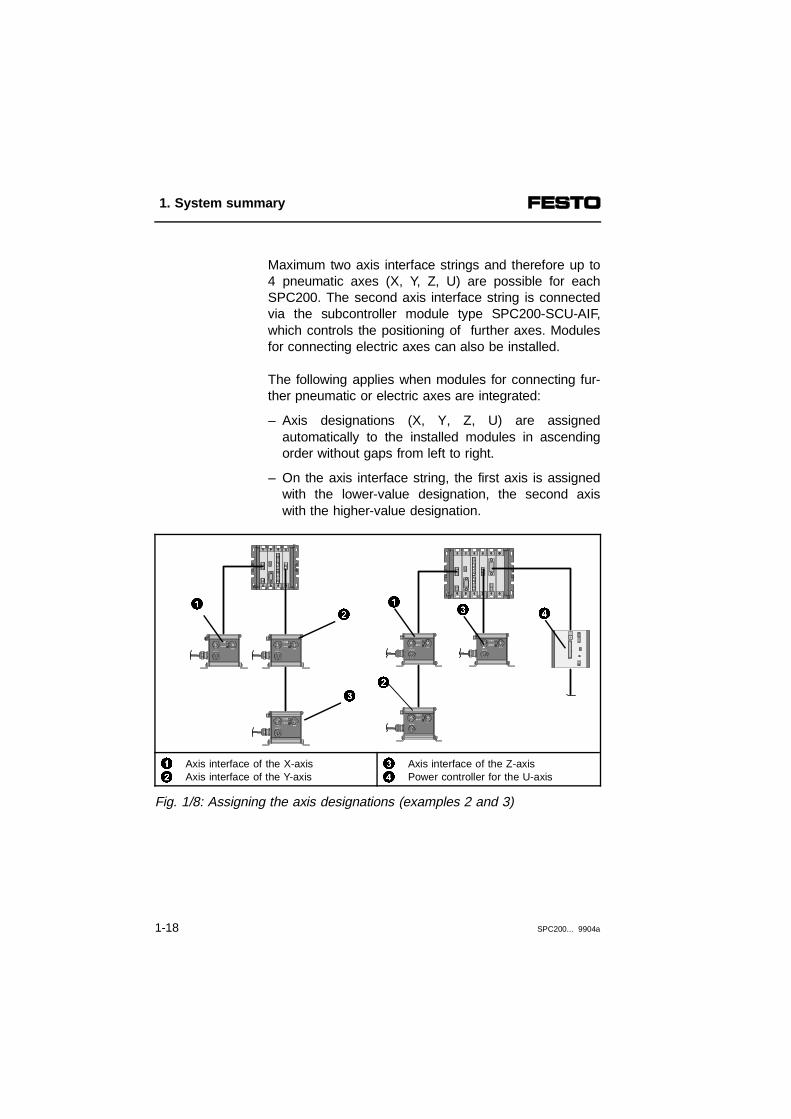
Maximum two axis interface strings and therefore up to4 pneumatic axes (X, Y, Z, U) are possible for eachSPC200. The second axis interface string is connectedvia the subcontroller module type SPC200-SCU-AIF,which controls the positioning of further axes. Modulesfor connecting electric axes can also be installed.
The following applies when modules for connecting fur-ther pneumatic or electric axes are integrated:
– Axis designations (X, Y, Z, U) are assignedautomatically to the installed modules in ascendingorder without gaps from left to right.
– On the axis interface string, the first axis is assignedwith the lower-value designation, the second axiswith the higher-value designation.
12
Axis interface of the X-axisAxis interface of the Y-axis
34
Axis interface of the Z-axisPower controller for the U-axis
Fig. 1/8: Assigning the axis designations (examples 2 and 3)
2
3 411
3
2
1. System summary
1-18 SPC200... 9904a
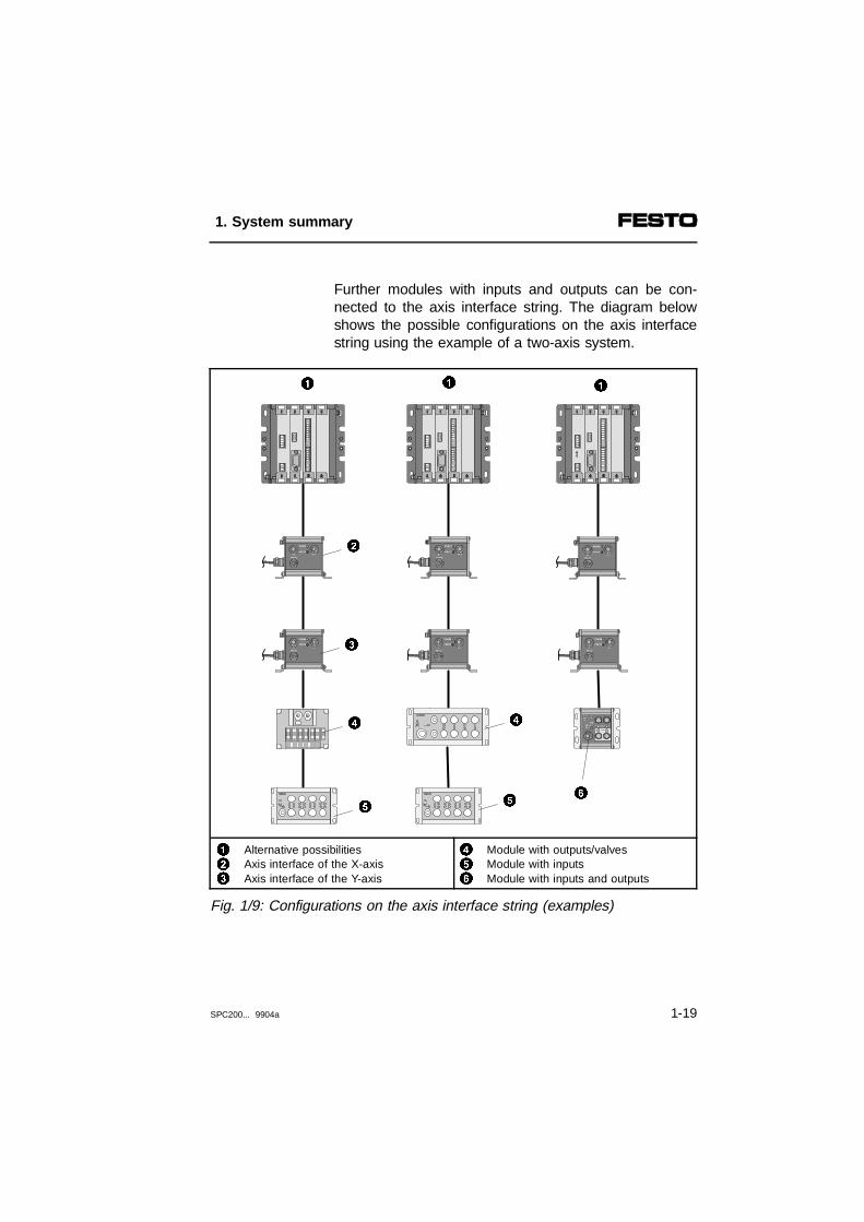
Further modules with inputs and outputs can be con-nected to the axis interface string. The diagram belowshows the possible configurations on the axis interfacestring using the example of a two-axis system.
123
Alternative possibilitiesAxis interface of the X-axisAxis interface of the Y-axis
456
Module with outputs/valvesModule with inputsModule with inputs and outputs
Fig. 1/9: Configurations on the axis interface string (examples)
1 11
2
4
5
4
56
3
1. System summary
SPC200... 9904a 1-19
The I/O function module (6) or the module with outputs(4) can be connected, if required, to the OUT connec-tion of the axis interface (2 or 3). Modules with out-puts (4) have a connection for coupling to an input mo-dule (5).
Input modules can also be connected directly to theaxis interface.
The individual modules are connected together bymeans of the CP cable. The transfer of information be-tween the modules and the SPC200, as well as theprovision of the operating and load voltages is made viathis cable. The identification of all the modules con-nected is made automatically by the SPC200.
1. System summary
1-20 SPC200... 9904a

1.4 Operating modes of the SPC200
The SPC200 offers different operating modes to suit thevarious applications. The functions of the digital inputsand outputs of the SPC200 depend on the operatingmode set. The following operating modes are available:
– start/stop mode
– record select mode
In start/stop mode the SPC 200 can control simple po-sitioning tasks both independently as well as with ahigher-order PLC/IPC. For this purpose, freely pro-grammable inputs and outputs are available in thisoperating mode.
Start/stopmode
Positioning programs can be started and stopped eitherwith the control panel, a control console or with ahigher-order PLC/IPC.
The command Programmed stop (M00) can be used forloose coupling to a higher-order PLC/IPC. With thiscommand you can synchronize the program sequenceof the SPC200 with externally controlled processes.
1. System summary
SPC200... 9904a 1-21

This operating mode supports close coupling of theSPC200 with a higher-order PLC/IPC. The completeprogram sequence is controlled here by the PLC/IPC.This PLC/IPC passes on positioning tasks in the formof record numbers to the SPC200 via digital I/Os.
Recordselection
mode
If the I/O modules are used, NC records 0...31 of theactive program, which normally contain only positioningtasks, can be retrieved via 5 digital inputs. ThePLC/IPC can therefore access up to 32 positions. Themaximum permitted number of NC records (1000 NCrecords) can be accessed via field bus modules.
1. System summary
1-22 SPC200... 9904a
1.5 Multi-axis applications with the SPC200
The SPC200 axis controller offers the possibility of par-allel program processing and supports the implementa-tion of multi-axis applications. An SPC200 can controlup to 4 axes. It thereby supports the:
– coordinated operating mode
– autonomous operating mode
Parallel program processing is not usually used in thecoordinated operating mode. Only one program isdefined as the starting program. NC records with posi-tioning tasks for all axes are programmed in this pro-gram.
coordinatedmode
If, for example, a positioning command refers to all theaxes, it is not completed until all the axes have reachedthe target position. The movement sequence of all theaxes is thus synchronized.
When multi-axis systems are implemented, the con-nected axes can be divided into two asynchronouslyfunctioning independent work stations. This enables twoindependent single or multi-axis systems to be im-plemented at low cost with one SPC200.
Autonomousmode
In autonomous mode, the two programs running paralleleach contain positioning tasks for a certain work sta-tion. In this way for example, a loading station and anunloading station can be controlled with just oneSPC200.
1. System summary
SPC200... 9904a 1-23

1.6 Commissioning and programming options
The SPC200 can be commisssioned and programmedby means of the:
– operating panel type SPC200-MMI-1
– WinPISA software package
You can commission and program single and multi-axissystems by means of the control panel. WinPISA offersan extended scope of functions and a very user-friendlyinterface. The table below provides a brief overview.
Subject Functions Controlpanel
WinPISA
Configuration - Input of axis parameters- Input of application parameters- Input of controller parameters
ä
ä
ä
ä
ä
ä
Programming - Input of programs- Input of positions- Teach editor for positions- Project backup functions
ä
ä
ä
-
ä
ä
ä
ä
Commissioning - Test functions for components- Program test in individual steps- Extended test functions- Program upload/download- Starting and stopping
programs
ä
ä
--ä
ä
ä
ä
ä
ä
Service - Updating the SPC200 firmwareby download
- Readout of statistical diagnostic data
-
-
ä
ä
Analysis andoptimizing
- Grafic display of position values- Input of extended system data
--
ä
ä
1. System summary
1-24 SPC200... 9904a

The plug-in control panel type SPC200-MMI-1 has atwo-line LCD display. Up to 16 characters can be dis-played on each line. There are 6 operating keys withwhich all functions can be accessed by means ofmenus. The control panel can be placed directly on theSPC200.
Control panel
123
Display (LCD display with 2 x 16 characters)Touch-sensitive keyboardInterface to the SPC200 on the rear
Fig. 1/10: Operating panel type SPC200-MMI-1
The control panel offers all the functions necessary forcommissioning, programming, diagnosis and operationdirectly on the SPC200. It also provides functions forediting position registers and programs.
1
3
2
1. System summary
SPC200... 9904a 1-25
Positions or programs can be entered on the keyboardwith the aid of menus. When your positioning system isfully installed, you can use the teach functions in orderto move easily to positions and transfer them to theposition register.
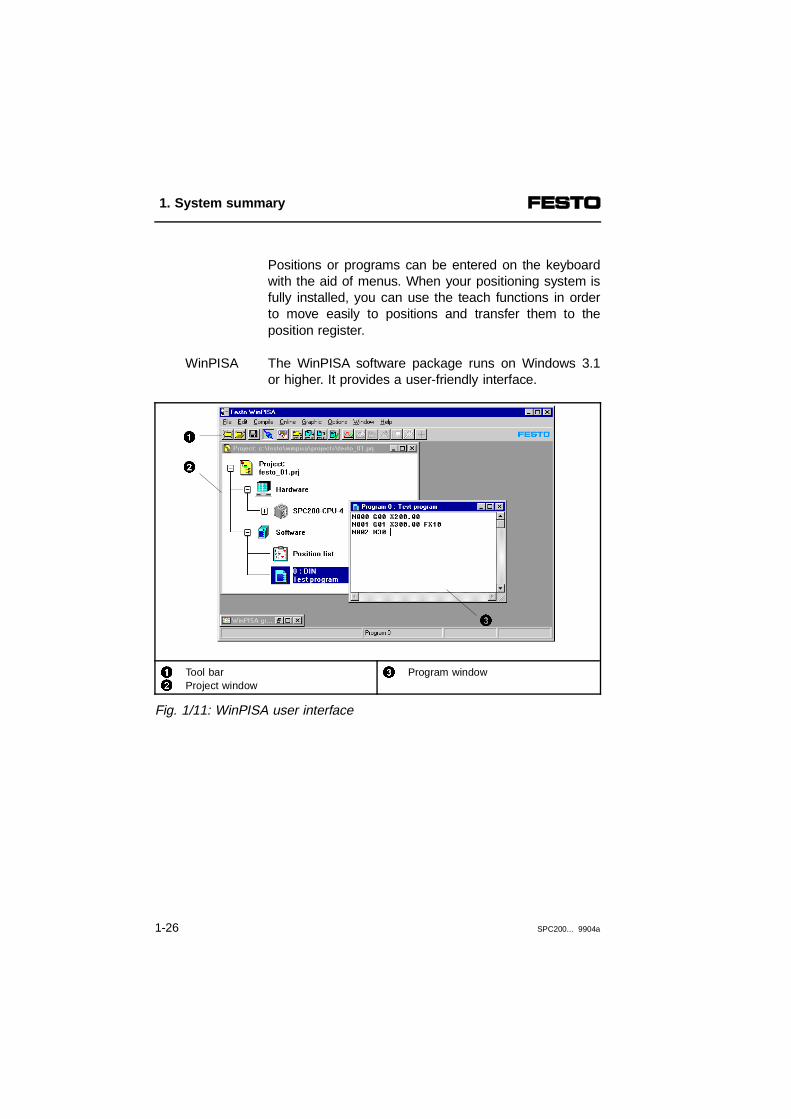
The WinPISA software package runs on Windows 3.1or higher. It provides a user-friendly interface.
WinPISA
12
Tool barProject window
3 Program window
Fig. 1/11: WinPISA user interface
3
1
2
1. System summary
1-26 SPC200... 9904a
The WinPISA project window offers rapid access to allproject data. All project components, such as the posi-tion list, programs and configuration data are showngraphically in the project window. One double-click issufficient to check or amend settings.
WinPISA provides the following functions:
– graphically supported configuration of the current pro-ject
– user-friendly editor for NC programming, based onDIN 66025
– load functions for programs, projects, etc.
– graphical function for analysing the positioning beha-viour
WinPISA supports single-axis and multi-axis applica-tions with up to four axes.
1. System summary
SPC200... 9904a 1-27

1.7 I/O address range of the SPC200
A complete word (16 bits) for inputs and/or outputs isavailable for each component and each I/O module, ir-respective of the number of I/Os which are integrated.
Configuration of the SPC200 Maximum address range
without field busmodule
with field busmodule
First I/O module - I0.0 ... I0.9 1) Q0.0 ... Q0.7 1)
I/O modules on first axis interface string I1.0 ... I1.15 Q1.0 ... Q1.15
Second I/O module First I/O module I2.0 ... I2.9 Q2.0 ... Q2.7
I/O modules on second axis interface string I3.0 ... I3.15 Q3.0 ... Q3.15
Third I/O module Second I/O module I4.0 ... I4.9 Q4.0 ... Q4.7
Fourth I/O module Third I/O module I5.0 ... I5.9 Q5.0 ... Q5.7
- Field bus module I10.0 ... I13.15 2) Q10.0 ... Q13.152)
1) Address range not available if a field bus module is used2) Address range not available without a field bus module
1. System summary
1-28 SPC200... 9904a

The diagram below shows an example.
1 These I/Os are reserved partly by pre-assigned functions(control inputs and outputs)
Q= outputI = input
Fig. 1/12: Address assignment without field bus module (example)
I2.0 ... I2.9Q2.0 ... Q2.7
1
Q1.0 ... Q1.11
Q3.0 ... Q3.15
I3.0 ... I3.15
I4.0 ... I4.9Q4.0 ... Q4.7
I0.0 ... I0.9Q0.0 ... Q0.7
I1.0 ... I1.15
1. System summary
SPC200... 9904a 1-29

1. System summary
1-30 SPC200... 9904a

Chapter 2
Fitting
2. Fitting
SPC200... 9904a 2-I

Contents
2. Fitting
2.1 Inserting and removing modules ................................................... 2-52.2 Mounting the basic unit ................................................................. 2-92.3 Fitting the control panel ............................................................... 2-122.4 Fitting the axis interface and I/O function module ...................... 2-142.5 Instructions on fitting the pneumatic axis .................................... 2-19
2. Fitting
2-2 SPC200... 9904a

This chapter describes how to fit and remove SPC200components as well as how to fit the following compo-nents:
Contents ofthis chapter
– the SPC200 basic unit
– the control panel
– the axis interface
– the I/O function module
This chapter also contains instructions on how to fit the pneumatic axis.
General instructions on fitting electromechanical axes,power controllers and sensors can be found in the ma-nual for the electric positioning system typeP.BE-ATP-....
Furtherinformation
Detailed information can be found in the instructions en-closed with the products. Further information on theelectric axis can be found in the instructions for therelevant module.
2. Fitting
SPC200... 9904a 2-3

WARNINGBefore starting assembly work, switch off the follow-ing in the order specified:1. the compressed air supply2. the load and operating voltages on the SPC200
and if necessary, the load voltage supply on the axis interface string.
By doing this you will avoid:
– Unintentional movements of the connected actuators.
– Uncontrolled movements of loose tubing.
– Undefined switching states.
2. Fitting
2-4 SPC200... 9904a

2.1 Inserting and removing modules
CAUTIONIncorrect handling can cause damage to the modules, therefore:• Do not touch the electrical contacts of the
components.• Pay due attention to handling specifications
for electrostatically vulnerable components.• Before inserting or removing modules you must
ensure that you are electrostatically dischargedto protect the modules against static discharges.
The SPC200-CPU-... rack serves as a housing for theSPC200 modules. The SPC200 processor and memoryare mounted on the integrated backplane. The modulesplugged in are connected through this backplane.
The modules are fixed to the rack with a safety catch.Consequently, no tools are required for insertion orremoval.
The slots are marked 1 to 4 or 6 from left to right. Slot1 is reserved for the power supply module (type SPC-200-PWR-AIF). Other modules can be inserted in slots2 to 4 or 6 as desired. The individual identification of allthe fitted components is carried out automatically.
Slots
2. Fitting
SPC200... 9904a 2-5

Component Type designation Maximum number
Power supply module SPC200-PWR-AIF 1
Diagnostic module SPC200-MMI-DIAG 1
Subcontroller module SPC200-SCU-AIF 1
Field bus module SPC200-COM-... 1
Reference value modules SPC200-2AI-U 2
Stepping motor indexer modules SPC200-SMX 3
I/O modules SPC200-DIO 3 or 4 1)
1) Maximum 4 I/O modules if a field bus module is not installed.
Recommendation
– When installing a subcontroller module or steppingmotor module, check whether the modules must beinstalled in a certain sequence. For operation, axisdesignations (X...U) are assigned automatically tothese modules in ascending order without gaps fromleft to right (see chapter 1).
– Fit the subcontroller module if possible in the slot tothe far right. The cable screening/shield can then beconnected without difficulty to the earth connectionon the right hand side.
– If you are using a control panel, fit the steppingmotor module and field bus module, if applicable,with at least one free slot between it/them and thediagnostic module.
2. Fitting
2-6 SPC200... 9904a
WARNINGActuators can be accidentally activated and theSPC200 damaged, if modules are inserted orremoved with the power switched on.Before installation or maintenance work switch offthe following power sources in the following order:1. compressed air supply2. the load supply and operating voltage supply of
the SPC200.
The procedure for installing the modules in the rack isas follows:
Installing modules
1. Switch off the compressed air supply and operatingvoltage supply.
2. If necessary, unlock the safety catches and removeany blanking plate.
3. Take hold of the front plate of the module and slideit into the guide rail. Be careful not to tilt the modulewhen you are sliding it into the slot, and make surethat none of the components on the board aredamaged.
4. Make sure that the pins on the connectors arecorrectly aligned. Then with a light pressure of thefingers push the module fully home. The safetycatches will then lock automatically (see Fig. 2/1).
2. Fitting
SPC200... 9904a 2-7

123
Direction for unlockingLocks automaticallySafety catches
456
Front plate of moduleContact strip Guide rail
Fig. 2/1: Installing modules
The procedure for removing a module is as follows:Removing modules
1. Switch off the compressed air supply and operatingvoltage.
2. Unscrew and remove the connecting cable on thefront of the module.
3. Press both safety catches to unlock (see Fig. 2/1)and carefully pull out the module.
4. Close any unoccupied slots with blanking plates.
65
1
4
21
3
2. Fitting
2-8 SPC200... 9904a

2.2 Mounting the basic unit
There are two methods of installing the SPC200 in aswitch cabinet:
– Screwing it directly to the wall of the cabinet.
– Fastening it to a top hat rail.
PLEASE NOTEFit the SPC200 or the hat rail so that there is sufficent space for heat dissipation (at least 40 mmabove and below).
Screw method of installation
You will need:
– a clear area of approx. 126 x 120 mm.
– four holes for screw size M4 (for dimensions see Fig.2/2).
1 SPC200-CPU-4: 117 mmSPC200-CPU-6: 158 mm
Fig. 2/2: Screw method of installation
94 mm
1
2. Fitting
SPC200... 9904a 2-9

Fitting with hat rail
In order to mount the rack on a top hat rail you willneed installation set CPV10/14-VI-BG-NRH..This set comprises 2 clips, 4 M4x10 bolts und 2 clampswith springs (see figure 2/3).
The rack is mounted on the top hat rail as follows:
1. Make sure that the surface on which the rack is tobe located can bear the weight of the SPC200.
2. Fasten a top hat rail (mounting rail EN50022 -35x7.5; width 35 mm, height 7.5 mm).
3. Secure the rail to the wall of the cabinet at min.100 mm intervals.
4. Attach the 2 clips (2) with the enclosed M4x10 bolts(1) to the bracket of the rack (see diagram below).Make sure that when the fastening bolts (5) in theclips are tightened they pass through the recess inthe rack.
5. Hook the rack on to the top hat rail. Secure the rackwith the clamps (4) so that it does not tip over orslip out.
2. Fitting
2-10 SPC200... 9904a

123
M4 x 10 boltClipTop hat rail
45
ClampFastening bolts
Fig. 2/3: Rail mounting for the rack
The procedure for removing the rack is as follows:
1. Remove the clamps.
2. Withdraw the rack.
2
4
3
5
1
2. Fitting
SPC200... 9904a 2-11

2.3 Fitting the control panel
WARNINGIf the control panel is plugged into or disconnectedfrom the SPC200 while the power supply is switchedon, actuators may be activated unintentionally andboth the SPC200 and the control panel may bedamaged.Before undertaking installation and/or maintenancework, switch off the following sources of power in thesequence specified:1. the compressed air supply2. the load voltage and operating voltage supplies for the SPC200.
Control panel type SPC200-MMI-1 can be pluggeddirectly onto the diagnostic module type SPC200-MMI-DIAG of the SPC200 (see figure 2/4). Proceed with thefitting as follows:
1. Switch off the compressed air supply.
2. Switch off the operating voltage and the load voltagefor the SPC200.
3. Carefully place the control panel onto the diagnosticmodule type SPC200-MMI-DIAG of the SPC200.Make sure that the plugs (3) and sockets (6) arecorrectly aligned before you plug the control panel incompletely.
4. Make sure that the locking pins (2) clip into place.
2. Fitting
2-12 SPC200... 9904a

123
Control panel (side view)Locking pinPlug on control panel
456
Diagnostic moduleRecess for locking pinsSocket for control panel (X3)
Fig. 2/4: Control panel installation
Proceed as follows when dismantling:
1. Switch off the compressed air supply.
2. Switch off the operating voltage and the load voltagefor the SPC200.
3. Carefully remove the control panel from thediagnostic module type SPC200-MMI-DIAG.
2
1
3
4
5
6
5
2
2. Fitting
SPC200... 9904a 2-13

2.4 Fitting the axis interface and I/O function module
This section describes how to fit the I/O functionmodule SPC-FIO-... and the SPC-AIF-... axis interface.
Axis interface installation
The SPC-AIF-... axis interface, designed as a field unit,can be attached either vertically or horizontally to a flatsurface using the angle brackets supplied. The follow-ing areas will be required for installation depending onthe method of fastening:
Method of fastening Area required
Horizontal approx. 66 mm x 70 mm
Vertical approx. 66 mm x 30 mm
The dimensions for the four threaded holes for M4 sizebolts and the installation of the angle brackets areshown in the following figure.
2. Fitting
2-14 SPC200... 9904a
123
Fitting the angle bracket horizontallyRight-angle plugFitting the angle bracket vertically
Fig. 2/5: Installation of the SPC-AIF-... axis interface
• Secure the axis interface with at least 3 bolts.
66 m
m
8.45
mm
72 m
m16
.9 m
m
95 mm
85.8 mm
30 mm
2
1
81 mm
34 mm
3
3
2. Fitting
SPC200... 9904a 2-15

Fitting the I/O function module
I/O Function modules are designed for mounting on aflat surface or on a top hat rail.
A surface area of approx. 70 x 80 mm is required tomount the module. The following diagram shows thepositions of the four holes for the M4 screws.
Wallmounting
1 SPC-FIO-2E/2A-M8 I/O function module
Fig. 2/6: Dimensions for installing I/O function module
POWER
DIAGOUTPUT
PNP
0 1
INPUT/OUTPUT
INPUT0 1
40 mm
67 mm
1
2. Fitting
2-16 SPC200... 9904a

You will require the CP-TS-HS35 installation kit to installthe rack on a mounting rail. This kit consists of 2fastenings, 2 M4x12 bolts and two backing washers.
Installationon mounting
rail
The procedure for fitting the device is as follows:
1. Fit a top-hat rail (EN 50022 - 35x15 support rail;width 35 mm, height 15 mm).
2. Secure the top-hat rail to the mounting surface atleast every 100 mm.
3. Snap the two fastenings onto the mounting rail (see Fig. 2/7).
4. Secure the housing onto the fastening with the boltsand backing washer supplied, as shown in thefollowing illustration.
5. Tighten the bolts firmly. This will clamp the fasteningand the housing firmly to the rail.
123
FasteningMounting railHousing
45
M4x12 boltBacking washer
Fig. 2/7: Fitting the SPC-FIO-2E/2A-M8 to a mounting rail
2
1
3
5
4
2
2. Fitting
SPC200... 9904a 2-17

The procedure for removing the device is as follows:
1. Loosen the bolts.
2. Remove the housing.
3. Lever the fastening out of the mounting rail using ascrewdriver.
12
FasteningScrewdriver
Fig. 2/8: Dismantling the fastening
1
2
2. Fitting
2-18 SPC200... 9904a

2.5 Instructions on fitting the pneumatic axis
PLEASE NOTEInstall the cylinder, measuring system and valve inaccordance with the relevant operating instructions.
The following sections contain general rules which areimportant for the safe operation of a pneumatic axis.
Proportional directional control valve
– Install the proportional directional control valve asclose as possible to the cylinder. Short compressedair lines ensure the dynamics of the system.
– Place the proportional directional control valve atright angles to the direction of motion if you wish tomount it on moving components. This will ensure thatacceleration forces will have no effect on the valveslide setting.
– In an environment with strong electrical interference,the proportional directional control valve should be in-sulated from the mounting surface.
– Use high-flow silencers.
Measuring systems with control slides
– If you wish to use a measuring system with slidesunder harsh environmental conditions, mount it sothat the side with the control slides faces downwards.The drip edge on either side will then prevent ex-cessive soiling of the slide surfaces.
2. Fitting
SPC200... 9904a 2-19

Cylinders
CAUTIONFit shock absorbers on the cylinder, even in the caseof a cylinder with adjustable cushioning (PPV). Thiswill prevent damage in the event of operating and system failures.
CAUTIONLimit the range of travel using fixed end-stops if themeasuring system is shorter than the range of travel.This will prevent damage to the measuring system inthe event of operating and system failures.
Important for positioning accuracy
– Cylinder, guidance, measuring system and load mustbe connected in the direction of travel almost rigidly,well aligned and with very little play.
– The play between drive, guide, mass and measuringsystem must be smaller by a factor of 10 than therequired tolerance (max. 0.1 mm).
2. Fitting
2-20 SPC200... 9904a

Chapter 3
Installation
3. Installation
SPC200... 9904a 3-1

Contents
3. Installation
3.1 General instructions on installation ............................................... 3-43.2 Instructions on pneumatic installation ........................................... 3-53.2.1 Pneumatic emergency stop circuit .............................................. 3-153.2.2 Tubing for slide and yoke operation............................................ 3-193.3 Installing the SPC200.................................................................. 3-213.3.1 Selecting the power unit. ............................................................. 3-223.3.2 Connections of the power supply module ................................... 3-243.3.3 Connections of the diagnostic module ........................................ 3-303.3.4 Connections of I/O module SPC200-DIO-... ............................... 3-333.3.5 Connections of analogue input module type SPC200-2AI-U...... 3-423.3.6 Connections on the subcontroller module type
SPC200-SCU-AIF........................................................................ 3-453.4 Installing the modules on the axis interface string...................... 3-473.4.1 Installing the axis interface SPC-AIF-... ...................................... 3-513.4.2 Installing I/O function module SPC-FIO-2E/2A-M8 ..................... 3-56
3. Installation
3-2 SPC200... 9904a

This chapter describes how to fit the pneumatic axisand how to fit the SPC200 basic unit with the followingcomponents and modules:
Contents ofthis chapter
– the power supply module type SPC200-PWR-AIF
– the diagnostic module type SPC200-MMI-DIAG
– the I/O modules type SPC200-DIO
– the reference value module type SPC200-2AI-U
– the subcontroller module type SPC200-SCU-AIF
– the axis interface type SPC-AIF-...
– the I/O function module type SPC-FIO-E/2A-M8
In addtion, the chapter contains important rules on set-ting up an axis interface string.
Instructions on installing the field bus modules and mo-dules for coupling electric axes can be found in the ma-nual for the relevant module.
Furtherinformation
Further information on electric positioning systems canbe found in the manual Electric positioning systemstype P.BE-ATP-... .
3. Installation
SPC200... 9904a 3-3
3.1 General instructions on installation
CAUTIONUse only the specially adapted components fromFesto for setting up and wiring the system. Only inthis way can you guarantee the correct functioning ofthe system.
WARNINGSwitch-off the following in the order specified beforecarrying out installation and maintenance work:1. the compressed air supply2. the load and operating voltage supply to
the SPC200 and, if necessary, the load voltagesupply to the axis interface string.
In this way you will avoid:
– undesired movements of the connected actuators
– uncontrolled movement of loose tubing
– undefined switching states.
3. Installation
3-4 SPC200... 9904a

3.2 Instructions on pneumatic installation
PLEASE NOTEObserve the following instructions on pneumaticinstallation. Only then can you guarantee faultlessoperation.
1-8 Instructions on installation see following pages
Fig. 3/1: Summary of pneumatic installation
2
1
5
3
68
3
7
4
3. Installation
SPC200... 9904a 3-5

1 Compressed air
• Use only dried, non-lubricated 5 µm filtered compres-sed air at 4...8 bar, tolerance ± 1 bar. Pleaseobserve the permitted pressure range of the compo-nents used.
A service unit with a 5 µm filter is required for protectingthe proportional directional control valve against dam-age.
2 Service unit
• Use a service unit consisting of a compressed air fil-ter and a regulating valve (e.g. type LFR-...-D-... with5 µm filter element) as well as a safety start-up valve(e.g. HEL-...-...):
– without lubricator
– with a 5 µm filter
– with sufficiently large standard flow corresponding tothe air requirements of the connected axis when po-sitioning. Guide value: twice the standard rated flowof the valve (MPYE).
– Use a microfilter if you cannot avoid a small amountof oil mist emerging from the compressed air source.
3. Installation
3-6 SPC200... 9904a

3 Compressed air tubing and connectors
• If possible, use screw connectors from the QS orQSM series. In the case of drives with 3/8" connec-tion, CK screw connectors of type CK-3/8-PK-13 canalso be used.
• Use only straight connectors. If angled connectorscannot be avoided, use plug connectors from theFesto Quick Star series.
• Use connectors with as large a width as possible. Ifthe connections of the valve and the cylinder are notthe same size, select the largest possible width forthe smaller size.
• Depending on the screw connectors, always use thelargest possible tubing diameter.
• Do not use restrictors.
• Lay the cables so that they do not obstruct the posi-tioning range.
• Use only clean compressed air tubing and screwconnectors.
• Keep the tubing as short as possible.
Details on the permitted temperature and pressureranges of tubing and connectors can be found in thePneumatics Catalogue.
Variations in pressure of max. 1 bar are permitted forgood positioning behaviour during operation at the pro-portional directional control valve. A measuring pointcan be provided directly before the proportional direc-tional control valve for checking the stability of the sup-ply pressure.
3. Installation
SPC200... 9904a 3-7
4 Compressed air reservoir
• Install a compressed air reservoir (e.g. type VZS-...-B) between the service unit and the proportional di-rectional control valve if the positioning behaviourdoes not meet with your requirements and if youascertain variations in pressure of over 1 bar at themeasuring point during operation.
In this way you will minimise variations in pressure dur-ing operation. You may be able to overcome slight ex-cesses in the permitted pressure by using a supply linewith a larger cross section.
Reservoir volumes
The volume of the reservoir depends on the cylindervolume of the drive used and should be at least twiceas large as the volume of the cylinder used.
VP = 2 * VZ
V P = Buffer volume;V Z = Cylinder volume (VZ = r 2 * π * LZ)L Z = Cylinder stroke lengthr = Cylinder diameter / 2
3. Installation
3-8 SPC200... 9904a
5 Proportional directional control valve
Recommendation: Use only suitable cylinder-valvecombinations. The diagram below shows permitted pro-portional directional control valves for cylinders of typeDGP...-... and DGO-....
123
Proportional directional control valve type MPYE-5-...-010B Cylinder diameterCylinder length
Fig. 3/2: Suitable valve/cylinder combination
3
1
2
3. Installation
SPC200... 9904a 3-9

• Install the proportional directional control valve asclose as possible to the cylinder. Short compressedair tubing will ensure proper system dynamics.
• In environments with strong electrical interference, in-sulate the proportional directional control valve fromthe mounting surface.
• Mounting on moving components:Mount the proportional directional control valve atright angles to the direction of movement. Accelera-tion forces will then have no effect on the valve slidesetting.
123
Mounting at right angles to the direction of movementNot permittedProportional directional control valve MPYE-...
Fig. 3/3: Mounting on moving parts
Instructions on connecting the tubing with slide andyoke operation can be found in section 3.2.2. Instruc-tions on the pneumatic emergency stop circuit can befound in section 3.2.1.
• Use silencers with high nominal flow rate(e.g. U-1/8).
21
3
3. Installation
3-10 SPC200... 9904a

Reducing high exhaust noises
• Install larger silencers with the aid of tubing or con-duct the exhaust air into a small air reservoir andvent this with a large silencer. Ensure that there is asufficient flow rate through the connectors and thetubing (in the case of the PUN-8 tubing length max.1 m).
12
Ducted exhaust airCompressed air reservoir
3 Silencer
Fig. 3/4: Ducted exhaust air
6 Cylinder
Use only permitted cylinders of type DGP...-... or DGO-... with suitable guide. Other cylinders may only beused after agreement with Festo.
Use maximum 80% of the cylinder length as the work-ing stroke. In the case of cylinders with adjustablecushioning (...-PPV), the working stroke must not pro-ject into the range of the PPV as this would preventgood positioning. Details on the cushioning length canbe found in the Pneumatics Catalogue.
• Carefully loosen completely the adjusting screws forthe internal end position cushioning.
1
3
2
3. Installation
SPC200... 9904a 3-11

CAUTIONLimit the range of movement with end stops so thatthe measuring system covers the whole positioningrange. In this way you will protect the measuring system from damage.
12
Cylinder lengthWorking stroke (80%), outside of PPV
3 End stop
3/5: Permitted working stroke
• In the case of DGP(L) cylinders, use a double-sidedair supply for cylinders longer than 600 mm, in orderto ensure good positioning behaviour.
• Lubricate the cylinder guides in accordance with themaintenance intervals indicated in the operating in-structions for the cylinder or for the guide.
Requirements in respect of play
– The cylinder, guide, measuring system and load mustbe almost rigidly fixed in the direction of movement,be relatively free of play and correctly aligned witheach other.
– If required, select an adequately large energy supplyin order to minimise the effect of bending forces onthe positioning behaviour.
1
3
2
3. Installation
3-12 SPC200... 9904a

7 Mass load
The pneumatic axis must be operated with a permittedmass load for good positioning behaviour. The massload represents the total mass including the weight ofthe piston and slide to be moved. It comprises the toolload and the current work load.
The permitted mass load depends on:
– the cylinder diameter used,
– the fitting position,
– the operating pressure.
You can determine the permitted mass load with the aidof the following table:
Fittingposition
Maximum mass load Minimum mass load
horizontal(α = 0°)
mmax 0.1 * mmax
vertical(α = 90°)
0.33 * mmax 0.1 * mmax
diagonal(0° < α < 90°)
(1-2/3 sin α) * mmax 0.1 * mmax
α = Fitting position in [°]
mmax = d2 * Psys * 0.008 d = Cylinder diameter [mm]Psys = Supply pressure [bar]mmax = maximum mass load for horizontal
fitting position [kg]
3. Installation
SPC200... 9904a 3-13
Make sure that:
– the tool load is geater than or equal to the deter-mined minimum mass load. During positioning with-out work load the mass load will not therefore belower than the minimum value (recommendation). Ifnecessary, use an appropriate basic load.
– the work load together with the tool load does notexceed the determined maximum mass load.
– modifications to the mass during operation are takeninto account with command M37.
8 Measuring system
• Use only measuring systems of type MLO-POT-...-TLF or MME-MTS-...-AIF or cylinders with integratedmeasuring system type DGPI(L)-...-AIF.
• If you wish to mount a linear potentiometer with slideunder difficult ambient conditions (dusty environ-ment), mount it so that the side with the actuatingslide faces downwards. The double-sided drip edgewill then prevent excessive soiling of the sliding sur-face.
• Fit the linear potentiometer so that it is electricallyinsulated from the mounting surface. Use the clamp-ing brackets provided.
PLEASE NOTEThe positioning accuracy which can be achieved de-pends on the type of measuring system used.
3. Installation
3-14 SPC200... 9904a

3.2.1 Pneumatic emergency stop circuit
In order to put the system into a safe state in the eventof a breakdown, a pneumatic emergency stop circuit isrequired. Choose one of the following methods,depending on the constructional and operationalcharacteristics of your system:
– Cylinder at zero pressure during emergency stop
– Piston clamped during emergency stop
– Piston moves throttled to the left or right end positionduring emergency stop.
3. Installation
SPC200... 9904a 3-15

Emergency stop with shut-off valve
To switch the operating pressure on and off a shut-offvalve can be fitted between the maintenance unit andthe proportional directional control valve.
1 Shut-off valve for emergency stop
Fig. 3/6: Switching off the operating pressure
1
3. Installation
3-16 SPC200... 9904a

Universal emergency stop circuit
Fig. 3/7: Universal emergency stop circuit
3. Installation
SPC200... 9904a 3-17

The emergency stop circuit shown in Fig. 3/7 enablesall possible emergency stop variants. The behaviour ofthe cylinder depends on whether you close connection3 of shut-off valves 1.2 and 1.3, or connect compressedair or a flow control valve with a silencer.
Behaviour ofcylinder
Connection 3 of valve 1.2 Connection 3 of valve 1.3
Cylinder pressureless Connect flow control valve withsilencer 1)
Connect flow control valve withsilencer 1)
Piston clamped Close with plug Close with plug
Right end position Connect compressed air Connect flow control valve withsilencer
Left end position Connect flow control valve withsilencer
Connect compressed air
1) Flow control valves reduce the impact force if an EMERGNCY STOP valve does not function correctly.
3. Installation
3-18 SPC200... 9904a

3.2.2 Tubing for slide and yoke operation
Some linear units are suitable for either slide or yokeoperation. Note that the linear unit must be fitted withtubing in accordance with the method of operation ofyour system. When compressed air is applied via port 4of the proportional directional control valve, the slidemust move in the direction of the measuring systemzero point (electrical connection of the potentiometer). Ifcompressed air is applied via port 2, the slide mustmove away from the measuring system zero point.
PLEASE NOTEThe tubing must also be correct if you are usingcylinders with unilateral air connection.
If the valve is mounted parallel to the measuring systemand the tubing is not to be crossed, the electrical con-nections of the two devices must be on the same side.
Slideoperation
1 Electrical connection
Fig. 3/8: Tubing in slide operation
1
3. Installation
SPC200... 9904a 3-19
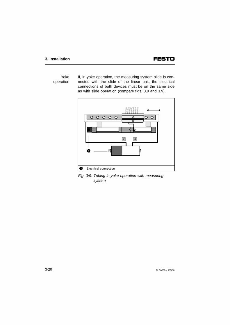
If, in yoke operation, the measuring system slide is con-nected with the slide of the linear unit, the electricalconnections of both devices must be on the same sideas with slide operation (compare figs. 3.8 and 3.9).
Yokeoperation
1 Electrical connection
Fig. 3/9: Tubing in yoke operation with measuringsystem
2 4
1
3. Installation
3-20 SPC200... 9904a

3.3 Installing the SPC200
WARNINGSwitch of the following in the order specified beforecarrying out installation and maintenance work:1. the compressed air supply2.– the load voltage supply for the field devices
and proportional directional control valves (plug X2, pin 1).
– the load voltage supply for the outputs (plug X6/X8, pin 8)
– if necessary, the load voltage supply for the axis interface string.
– the operating voltage supply for the internal electronics for the SPC200 and field devices (plug X2, pin 2).
In this way you will avoid:
– undesired movements of the connected actuators
– uncontrolled movement of loose tubing
– undefined switching states.
PLEASE NOTEMark the cables connected to the SPC200. In thisway you can avoid confusion with similar plugsduring conversion work.
3. Installation
SPC200... 9904a 3-21

3.3.1 Selecting the power unit.
WARNINGUse only power units which guarantee reliableisolation of the operating voltages as per IEC742/EN 60742/VDE 0551 with at least 4 kV isolationresistance (protected extra low voltage, PELV).Switch power packs are permitted if they guaranteereliable isolation in accordance with EN 60950/VDE0805.
By using PELV power units, protection against electricshock (protection against direct and indirect contact) inaccordance with EN 60204-1/IEC 204 is guaranteed onFesto valve terminals. Safety transformers with the ad-jacent designation must be used for supplying PELVnetworks. The valve terminals must be earthed in orderto ensure their function (e.g. EMC).
Recommendation:
• Use a closed loop power unit.
• Select a power unit which has sufficient output forfurther extensions.
• The current consumption depends on the numberand type of components connected. When selectingthe power unit, check that it has sufficient output.Calculate the total current consumption according tothe following table.
3. Installation
3-22 SPC200... 9904a

Current consumption at pin 1 of module SPC200-PWR-AIF
Current consumption of basic load of the electroniccomponents
500 mA
Load current consumption of simultaneously acti-vated outputs on module SPC200-DIO1)
+ _____ A
Sum of load current consumption of all proportionaldirectional control valves (appprox. 1.2 A je MPYE-...)
+ _____ A
Load current consumption of all simultaneously acti-vated CPV valve coils on the axisinterface string 1) 2)
+ _____ A
Load current consumption of all simultaneously acti-vated outputs on the axis interface string 1) 3)
+ _____ A
Sum of current consumption at pin 1 = _____ A ______ A
Current consumption at pin 2 of module SPC200-PWR-AIF
Current consumption of internal electronics of the SPC200- SPC200-CPU-4 (400 mA)- SPC200-CPU-6 (600 mA)
+ _____ A
Current consumption of all sensors connected to mo-dules SPC200-DIO (see manufacturer specifications)
+ _____ A
Current consumption of all modules which are sup-plied with current via the axis interface strings (logicvoltage)
+ _____ A
Sum of current consumption at pin 2 = _____ A +______ A
Total current consumption =______ A
1) Separate power supply possible or necessary 2) Current consumption depends on valve type (see Technical Specifications for valves)3) Internal consumption at logic 1 see Technical Specifications for modules
3. Installation
SPC200... 9904a 3-23

3.3.2 Connections of the power supply module
On the front of power supply module type SPC200-PWR-AIF you will find the following connecting and dis-play elements:
12345
Power supply module type SPC200-PWR-AIFCombicon screw terminal for axis interface string (X1)ERROR-LED for error display (red)POWER-LED for power supply green)3-pin Combicon screw terminal for power supply (X2)
Fig. 3/10: Connecting and display elements of thepower supply module
4
3
5
1
2
3. Installation
3-24 SPC200... 9904a

Operating voltage connection (X2)
The following components are supplied with + 24 V DCvia the operating voltage connection (X2):
– the load voltage supply for field devices and the pro-portional directional control valve, with emergencystop circuit; pin 1: + 24 V DC, tolerance -5 %/+25 %
– the internal electronics of the SPC200, of the con-nected modules and measuring systems;pin 2: + 24 V DC, tolerance -5 %/+25 %
PLEASE NOTEIn the case of the power supply and load voltages,the tolerance of - 5 % to + 25 % must be observedfor both current circuits.
PLEASE NOTECheck your EMERGENCY STOP circuit to seewhich measures are necessary to place yourmachine/system in a safe state in the event of anEMERGENCY STOP (e.g. switching off the loadvoltage, pressure).
• Check the 24 V operating voltage of the outputs whi-le your system is operating. Note that the operatingvoltage of the outputs must lie within the permittedtolerances even during full operation.
3. Installation
SPC200... 9904a 3-25

The diagram below shows the pin assignment of theoperating voltage connection on the power supply mo-dule.
Connection cross section area max. 1.5 mm2
1234
24 L: 24 V load supply (can be switched off separately)24 V: 24 V supply for internal electronics0 VEarth/ground connection (M4 thread)
Fig. 3/11: Operating voltage connection (X2)
The SPC200 has earth connections on the left and righthand sides of the rack.
Earth/groundconnection
PLEASE NOTEConnect one of the earth cables of the SPC200 withlow impedance (short cable with large cross-sectional area) to the earth potential.
In this way you can avoid faults caused by electromag-netic interference.
2
4
3
1
3. Installation
3-26 SPC200... 9904a

Example of connection
The following illustration shows the connections to pin 1and pin 2 of a common 24 V supply. Note that
– the tolerance limits for the load supply and circuitsupply must not exceed 24 V DC -5 % +25 %;
– in the case of the load supply, the voltage tolerancesfor the components connected to the axis interfacestring must also be observed.
1 Load supply (can be switched off separately)
Fig. 3/12: Example – Connecting a common 24 V power supply
1
0 V 24 V
24 V0 V
24 L
3. Installation
SPC200... 9904a 3-27
Plug for axis interface string (X1)
CAUTIONUse the special cable from Festo (type KSPC-AIF-...) for connecting the axis interface.Note the maximum permitted cable lengths on theaxis interface string (see section 3.4).
In this way you will avoid faults in the SPC200 and inthe modules connected to the axis interface string.
The bus signals, the operating voltage and the loadvoltage for the connected field devices are provided viathe 5-pin plug of the power supply module.
3. Installation
3-28 SPC200... 9904a

The KSPC-AIF-... connecting cable is supplied readyfitted with a 5-pin screw terminal..
CAUTIONThe axis interface connection does not haveprotection against incorrect polarity. Make sure thatthe contacts are correctly assigned if, for exampleyou connect the screw terminal yourself aftershortening the cable.
Pin assignment and wire colours of cable type KSPC-AIF-...
123
CAN-LOW (brown)CAN-HIGH (white)24 V (yellow)
456
0 V (green)24 V load voltage (grey)Earth connection
Fig. 3/13: Pin assignment of the plug for the first axis interface string (X1)
Connect the cable screening to the earth connection(6).
1
3
4
2
6
5
3. Installation
SPC200... 9904a 3-29
3.3.3 Connections of the diagnostic module
You will require a diagnostic module type SPC200-MMI-DIAG for commissioning, programming and diagnosing.This diagnostic module offers the following serial inter-faces:
– a connection for control panel type SPC-MMI-1;
– a connection for a PC. This serial interface is de-signed as a 9-pin Submin-D plug and complies withstandard RS-232.
The serial interface is operated with the following set-tings:
– Baud rate: 9.6 ... 115.2 kBaud
– Data bits: 8 bits
– Parity: even
– 1 stop bit
– No handshake
To connect a PC you will require:
– a screened connecting cable (e.g. Festo diagnosticcable type KDI-PPA-3-BU9)
– a PC with serial interface (RS-232) and with Win-PISA programming and commissioning software typeP.SW-WIN-PISA-.....
3. Installation
3-30 SPC200... 9904a

PLEASE NOTEIf you wish to use a different connecting cable, notethe following pin assignment. Use a screened cableand connect the screening to the plug housing.
You will then avoid faults in data transmission.
235
Pin 2: Received data (RxD)Pin 3: Transmitted data (TxD)Pin 5: Signal ground (SGND)
Fig. 3/13: Pin assignment of serial interface (X4)
Connect the diagnostic cable as follows:
– the 9-pin plug to the 9-pin socket on the diagnosticmodule
– 25-pin or 9-pin socket on the serial interface of yourPC.
2
5
3
3. Installation
SPC200... 9904a 3-31

The control panel type SPC200-MMI-1 can be placeddirectly on the upper interface when the power supply isswitched off.
CAUTIONThe control panel may be damaged if it is placed onthe interface when the power supply is switched on.Make sure that the power supply is switched offbefore the control panel is connected.
Fig. 3/15: Pin assignment of MMI socket (X3)
3. Installation
3-32 SPC200... 9904a

3.3.4 Connections of I/O module SPC200-DIO-...
You will require an I/O module type SPC200-DIO-.... forcontrolling the SPC200 via digital I/Os. This I/O modulehas 10 digital inputs and 8 digital outputs for the follow-ing functions:
– providing digital I/Os for controlling the SPC200 (onlyif no field bus module is fitted)
– providing freely programmable digital I/Os for control-ling peripherals.
PLEASE NOTEMaximum 3 I/O modules are permitted to operate on the field bus. Without a field bus module, 4 I/O modules can be fitted into a rack.
The logical functions of the digital inputs/outputs de-pend on the operating mode selected. Freely pro-grammable I/Os are only available in start/stop mode.
Control via digital I/Os or I/O modules is only possible ifno field bus module is installed. Identification of insertedmodules takes place automatically, starting with thepower supply module from left to right. The followingdiagrams show the assignment of plug X5/X7 and plugX6/X8 (inputs).
3. Installation
SPC200... 9904a 3-33

Inputs
Connection cross section area max. 1.5 mm2
123
"
24 V sensor supply (non floating)0 V (non floating)0: input 0...9: input 9
Fig. 3/16: Assignment of plug X5/X7 (inputs)
12
Three-wire sensorTwo-wire sensor
3 Contact
Fig. 3/17: Example of circuitry (PNP inputs)
3
2
"
1
2
1
3
0 V 24 V ± 25 %
9
012...
24 V 0 V
3. Installation
3-34 SPC200... 9904a

Outputs
Connection cross section area max. 1.5 mm2
12890
0: output 0...7: output 724 V external supply for outputs0 V external supply for outputs
Fig. 3/18: Pin assignment of plug X6/X8 (outputs)
12
Example 1Example 2
34
Not permittedLoad voltage
Fig. 3/19: Example of circuitry (outputs X6/X8)
How to supply the load voltage for plugs X2 and X6/X8via one power unit is shown in Fig. 4/1.
1
0
89
4
12
3
DC
AC0 V
24 V
012...
7
3. Installation
SPC200... 9904a 3-35
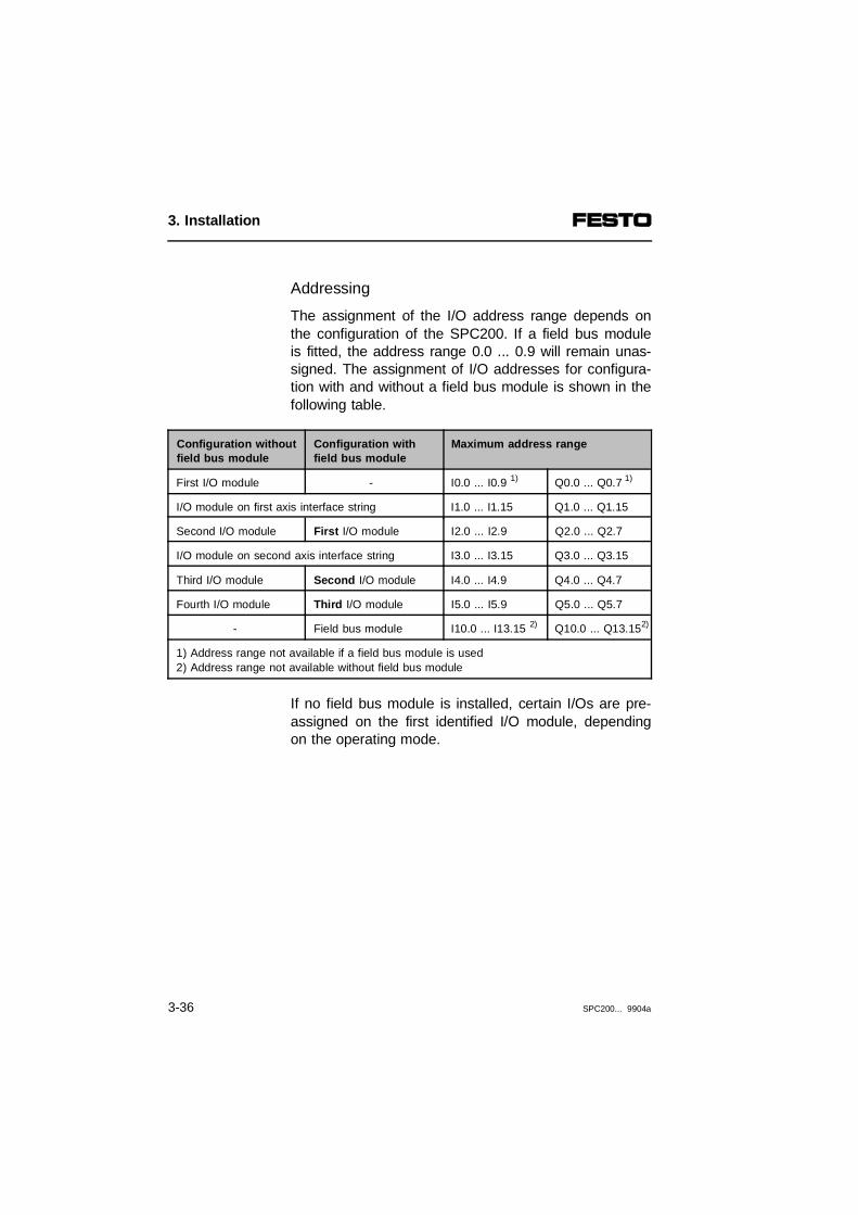
Addressing
The assignment of the I/O address range depends onthe configuration of the SPC200. If a field bus moduleis fitted, the address range 0.0 ... 0.9 will remain unas-signed. The assignment of I/O addresses for configura-tion with and without a field bus module is shown in thefollowing table.
Configuration withoutfield bus module
Configuration withfield bus module
Maximum address range
First I/O module - I0.0 ... I0.9 1) Q0.0 ... Q0.7 1)
I/O module on first axis interface string I1.0 ... I1.15 Q1.0 ... Q1.15
Second I/O module First I/O module I2.0 ... I2.9 Q2.0 ... Q2.7
I/O module on second axis interface string I3.0 ... I3.15 Q3.0 ... Q3.15
Third I/O module Second I/O module I4.0 ... I4.9 Q4.0 ... Q4.7
Fourth I/O module Third I/O module I5.0 ... I5.9 Q5.0 ... Q5.7
- Field bus module I10.0 ... I13.15 2) Q10.0 ... Q13.152)
1) Address range not available if a field bus module is used2) Address range not available without field bus module
If no field bus module is installed, certain I/Os are pre-assigned on the first identified I/O module, dependingon the operating mode.
3. Installation
3-36 SPC200... 9904a
Basic rules
If several I/O modules are fitted in a rack, you shouldobserve the following:
– The I/O module inserted on the left, nearest to thepower supply module, is the first I/O module. FurtherI/O modules are counted from left to right.
– If no field bus module is fitted, the first I/O moduleprovides five freely programable inputs and threefreely programmable outputs and the I/Os for control-ling the SPC200 (I0.0 ... I0.9 and Q0.0 ... Q0.7). TheI/Os of further I/O modules are freely programmable.
– If a field bus module is fitted, the address ranges(I0.0 ... I0.9 and Q0.0 ... Q0.7) are not available. Thefirst I/O module then occupies the addresses I2.0 ...I2.9 and Q2.0 ... Q2.7. Their I/Os are therefore alsofreely programmable.
Explanations of the I/O control signals in the relevantoperating mode can be found in chapter 5.
3. Installation
SPC200... 9904a 3-37

Pin assignment of front plug X5 for the first I/O modulefor operation without a field bus module
If no field bus module is fitted, the first I/O module willprovide the following control inputs:
Inputs with control function
Pin no. Designa-tion1)
Address2) Start/stop mode Record selection mode
1 24 V - 24 V sensor supply (non floating)
2 0 V - 0 V (non floating)
3 0 I0.0
freely programmable
REC_BIT 1
4 1 I0.1 REC_BIT 2
5 2 I0.2 REC_BIT 4
6 3 I0.3 REC_BIT 8
7 4 I0.4 REC_BIT 16
8 5 I0.5 SYNC_IB CLK_B
9 6 I0.6 SYNC_IA CLK_A
10 7 I0.7 STOP STOP
11 8 I0.8 START/RESET3) RESET3)
12 9 I0.9 ENABLE ENABLE
1) Designation on the module2) Addresses of the first installed I/O module with configuration without field bus module
(I = input)3) RESET (Program reset) in conjunction with 0-signal at STOP input
3. Installation
3-38 SPC200... 9904a

Pin assignment of front plug X6 for the first I/O modulefor operation without a field bus module
If no field bus module is fitted, the first I/O module willprovide the following control outputs:
Outputs with control function
Pin no. Designa-tion1)
Address2) Start/stop mode Record selectionmode3)
1 0 Q0.0freely programmable.
-
2 1 Q0.1 -
3 2 Q0.2 -
4 3 Q0.3 MC_B RC_B
5 4 Q0.4 MC_A RC_A
6 5 Q0.5 SYNC_OB ACK_B
7 6 Q0.6 SYNC_OA ACK_A
8 7 Q0.7 READY READY
9 24 V 24 V external supply for outputs
10 0 V 0 V external supply for outputs
1) Designation on the module2) Addresses of the first installed I/O module with configuration without field bus module
(Q = output)3) No freely programmable I/Os are supported in this operating mode
3. Installation
SPC200... 9904a 3-39

General pin assignments for I/O modules without spe-cial control functions
The word number (here x) depends on the configura-tion of the SPC200.
Configuration Word number x
Withoutfield bus module
Withfield bus module
Second I/O module First I/O module 2
Third I/O module Second I/O module 4
Fourth I/O module Third I/O module 5
Inputs without control function
Pin no. Designa-tion1)
Address2) Start/stop mode Record selection mode3)
1 24 V - 24 V sensor supply (non floating)
2 0 V - 0 V (non floating)
3 0 Ix.0
freely programmable
-
4 1 Ix.1 -
5 2 Ix.2 -
6 3 Ix.3 -
7 4 Ix.4 -
8 5 Ix.5 -
9 6 Ix.6 -
10 7 Ix.7 -
11 8 Ix.8 -
12 9 Ix.9 -
1) Designation on the module2) The word number (here x) depends on the configuration3) Freely programmable I/Os are not supported in this operating mode
3. Installation
3-40 SPC200... 9904a

General pin assignments for I/O modules without spe-cial control functions
The word number (here x) depends on the configura-tion of the SPC200.
Configuration Word number x
Withoutfield bus module
Withfield bus module
Second I/O module First I/O module 2
Third I/O module Second I/O module 4
Fourth I/O module Third I/O module 5
Outputs without control function
Pin no. Designa-tion1)
Address2) Start/stop mode Record selection mode3)
1 0 Qx.0
freely programmable
-
2 1 Qx.1 -
3 2 Qx.2 -
4 3 Qx.3 -
5 4 Qx.4 -
6 5 Qx.5 -
7 6 Qx.6 -
8 7 Qx.7 -
9 24 V - 24 V external supply for outputs
10 0 V - 0 V external supply for outputs
1) Designation on the module2) The word number (here x) depends on the configuration (Q = output)3) No freely programmable I/Os are supported in this operating mode
3. Installation
SPC200... 9904a 3-41
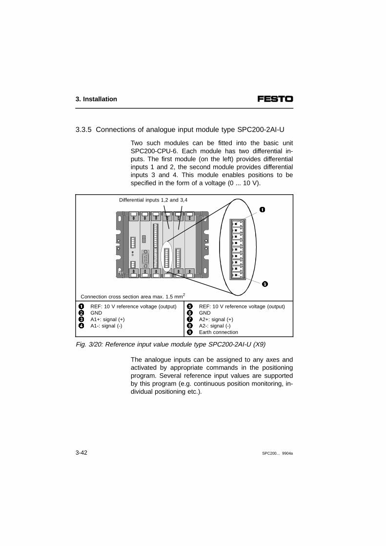
3.3.5 Connections of analogue input module type SPC200-2AI-U
Two such modules can be fitted into the basic unitSPC200-CPU-6. Each module has two differential in-puts. The first module (on the left) provides differentialinputs 1 and 2, the second module provides differentialinputs 3 and 4. This module enables positions to bespecified in the form of a voltage (0 ... 10 V).
Differential inputs 1,2 and 3,4
Connection cross section area max. 1.5 mm2
1234
REF: 10 V reference voltage (output)GNDA1+: signal (+) A1-: signal (-)
56789
REF: 10 V reference voltage (output)GNDA2+: signal (+) A2-: signal (-) Earth connection
Fig. 3/20: Reference input value module type SPC200-2AI-U (X9)
The analogue inputs can be assigned to any axes andactivated by appropriate commands in the positioningprogram. Several reference input values are supportedby this program (e.g. continuous position monitoring, in-dividual positioning etc.).
9
1
3. Installation
3-42 SPC200... 9904a

The voltage range is 0-10 V. With the aid of the analo-gue reference value input, you can determine by pro-gram any range for positioning within the possible posi-tioning range of the axis. The voltage value and theposition have the following relationship to each other:
Voltage Description
0 V......10 V
Smallest position value......Largest position value
Connecting analogue sensors
WARNINGImproper installation can lead to operating faults ande.g. cause undesired movements of the actuators.Please observe the installation instructions below:
• Use a screened cable twisted in pairs for theanalogue reference value specification.
• Do not place cables in the vicinity of or parallel tocables with high interference levels. If necessary, useseparate cable channels or bundles or even use se-parate cables.
• Always connect the screening for analogue signalcables on one side to the earth conductor (pin 9).
Recommendation: Use short signal cables whereverpossible. The maximum length of the cable should notexceed 4 m.
3. Installation
SPC200... 9904a 3-43
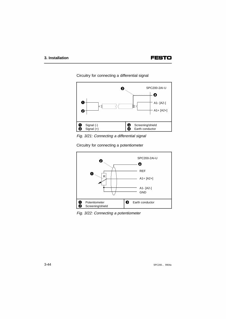
Circuitry for connecting a differential signal
12
Signal (-)Signal (+)
34
Screening/shieldEarth conductor
Fig. 3/21: Connecting a differential signal
Circuitry for connecting a potentiometer
12
PotentiometerScreening/shield
3 Earth conductor
Fig. 3/22: Connecting a potentiometer
1
2
SPC200-2AI-U
A1+ [A2+]
A1- [A2-]
4
3
1R
SPC200-2AI-U
GNDA1- [A2-]
A1+ [A2+]
4
REF
2
3. Installation
3-44 SPC200... 9904a

3.3.6 Connections on the subcontroller module typeSPC200-SCU-AIF
In its basic design, the SPC200 can control the posi-tioning of two pneumatic axes. With the subcontrollermodule, maximum four pneumatic axes can be oper-ated with just one SPC200. The subcontroller moduleprovides a connection for a second axis interface stringand controls the positioning of the connected axes.Maximum two pneumatic axes are permitted for eachaxis interface string.
CAUTIONUse the special cable from Festo (type KSPC-AIF-...)for connecting the axis interface.Please observe the maximum permitted cablelengths on the axis interface string (see section 3.4).
In this way you will avoid malfunctioning of both theSPC200 and the modules connected to the axis inter-face string.
The bus signals, the operating voltage and the loadvoltage for the connected field devices are supplied viathe 5-pin plug on the power supply module. The con-necting cable type KSPC-AIF-... is supplied ready touse and fitted with a 5-pin screw terminal.
CAUTIONThe axis interface connection is not protectedagainst incorrect polarity. Make sure that the connec-tions are correct, if, e.g. you fit the screw terminalyourself after shortening the cable.
3. Installation
SPC200... 9904a 3-45

Pin assignment and core colours of cable type KSPC-AIF-...
1234
CAN-LOW (brown)CAN-HIGH (white)24 V (yellow)0 V (green)
56
7
24 V load voltage (grey)Groove with inserted coding pinEarth connection
Fig. 3/23: Pin assignment of the plug for the secondaxis interface string (X10)
Connect the cable screening to the earth connection(6).
PLEASE NOTEIn order to avoid confusion between connections X10and X1, assign different codes to the connections. In-sert the coding pins supplied into different grooves inthe connector strips. Remove the appropriate plasticlugs from the relevant plugs.
1
3
4
2
7
6
5
3. Installation
3-46 SPC200... 9904a

3.4 Installing the modules on the axis interface string
WARNINGCables with high levels of interference can causeelectromagnetic faults. Do not, therefore, place thefollowing in the vicinity of such cables: - CP cable- measuring system cable- proportional directional control valve cable.
PLEASE NOTEConnect the earth/ground connection of the moduleswith low impedance (short cable with large diameter)to the earth potential.
In this way, you will avoid interference caused by elec-tromagnetic influences.
3. Installation
SPC200... 9904a 3-47
You must observe the following basic rules when themodules are installed on the axis interface string:
Basic rules
1) Maximum length of string
– The maximum permitted string length is 30 m.
2) External load voltage supply
– If the following modules are used, the external loadvoltage supply module type SPC-AIF-SUP-24V mustbe installed directly before the relevant module:- I/O function module (type SPC-FIO-2E/2A) - with 2-axis systems: CP valve terminal (type CPV...)
A load-dependent drop in voltage occurs at the axisinterface. With incorrect installations this can lead to adrop in the load voltage below the permitted tolerance.
3) Configuration on the axis interface string
– At first, maximum two axis interfaces are connectedto the SPC200. If required, the I/O function moduleor at first a CP module with outputs and then a CPmodule with inputs can be connected to the last axisinterface.
4) Terminating resistor
– If a CP I/O module, a CP valve terminal or an axisinterface is at the end of the axis interface string, theplug with integrated terminating resistor type KABS-M9-R100 must be installed in the outgoing CP cable(e.g. connection OUT) of this module.
3. Installation
3-48 SPC200... 9904a
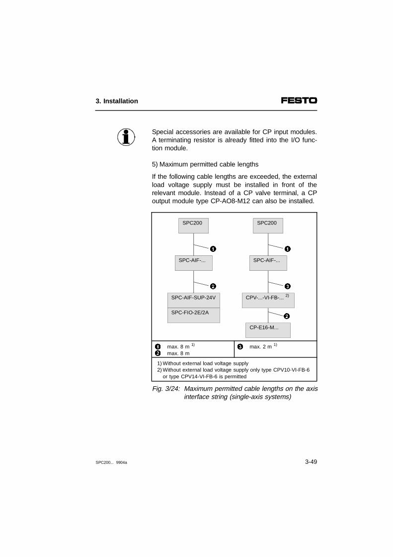
Special accessories are available for CP input modules.A terminating resistor is already fitted into the I/O func-tion module.
5) Maximum permitted cable lengths
If the following cable lengths are exceeded, the externalload voltage supply must be installed in front of therelevant module. Instead of a CP valve terminal, a CPoutput module type CP-AO8-M12 can also be installed.
12
max. 8 m 1)
max. 8 m3 max. 2 m 1)
1) Without external load voltage supply 2) Without external load voltage supply only type CPV10-VI-FB-6
or type CPV14-VI-FB-6 is permitted
Fig. 3/24: Maximum permitted cable lengths on the axisinterface string (single-axis systems)
SPC200
SPC-AIF-...
CPV-...-VI-FB-... 2)
CP-E16-M...
SPC200
SPC-AIF-...
SPC-AIF-SUP-24V
SPC-FIO-2E/2A
1
2
1
2
3
3. Installation
SPC200... 9904a 3-49

12
max. 8 m 1)
max. 8 m 3 max. 5 m 1)
1) Without external load voltage supply
Fig. 3/25: Maximum permitted cable lengths on the axis interface string(two-axis systems)
SPC200
1
SPC-FIO-2E/2A
SPC-AIF-...
1
SPC-AIF-...
2
SPC-AIF-SUP-24V
SPC200
SPC-AIF-...
CPV-...-VI-FB-...
CP-E16-M...
3
2
1
SPC-AIF-...
2
SPC-AIF-SUP-24V
SPC200
SPC-AIF-...
CPV-...-VI-FB-...
CP-E16-M...
1
2
3
SPC-AIF-...
2
SPC-AIF-SUP-24V
3. Installation
3-50 SPC200... 9904a
3.4.1 Installing the axis interface SPC-AIF-...
WARNINGInterference due to electromagnetic sources is liableto cause sudden compensatory movements of theaxis. Follow the installation procedure below in orderto prevent this electromagnetic interference.
– Connect the earth connection of the axis interfacewith low impedance (short cable with large diameter)to the earth potential.
– Do not lay any axis interface cables, CP cables,measuring system cables or proportional directionalcontrol valve cables near or parallel to cables withhigh interference levels.
– Use only original cables. Attach the plug with thehelp of the union nut, so as to avoid any uninten-tional slackening caused by oscillation etc.
– Seal any unused connectors with the protective capsprovided. Only then is the IP 65 type of protectionensured.
PLEASE NOTEMaximum two axis interfaces may be connected toan axis interface string. Interface types for differentmeasuring systems may be mixed here.
3. Installation
SPC200... 9904a 3-51
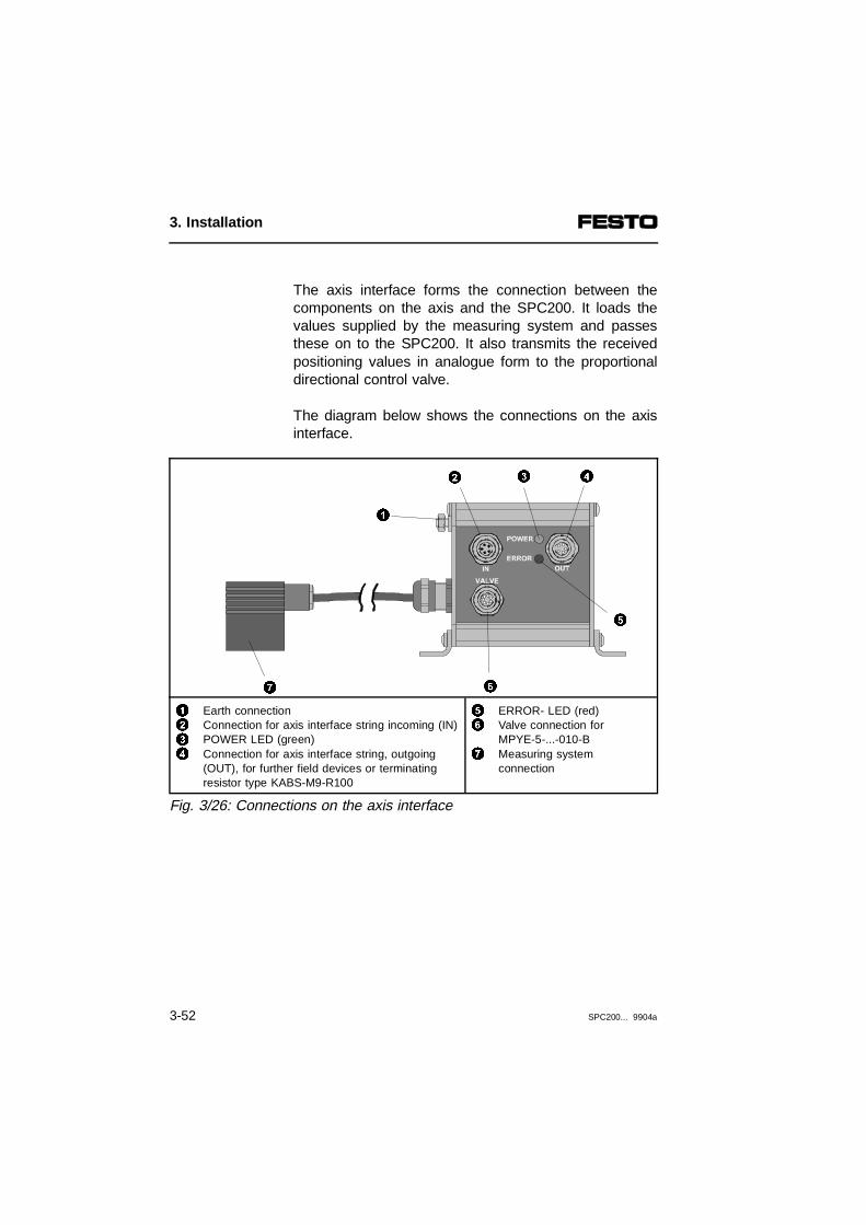
The axis interface forms the connection between thecomponents on the axis and the SPC200. It loads thevalues supplied by the measuring system and passesthese on to the SPC200. It also transmits the receivedpositioning values in analogue form to the proportionaldirectional control valve.
The diagram below shows the connections on the axisinterface.
1234
Earth connectionConnection for axis interface string incoming (IN)POWER LED (green)Connection for axis interface string, outgoing(OUT), for further field devices or terminatingresistor type KABS-M9-R100
56
7
ERROR- LED (red)Valve connection for MPYE-5-...-010-BMeasuring systemconnection
Fig. 3/26: Connections on the axis interface
7 6
432
5
1
3. Installation
3-52 SPC200... 9904a

Connecting the axis interface to the SPC200
WARNINGObserve the maximum permitted cable lengthsbetween the individual modules on the axis interfacestring and the SPC200 (see section 3.4).Use only the original cables mentioned below for connecting the axis interface.
Cable type Description
KSPC-AIF-1-WD-... Connecting cable for the first axis
KVI-CP-2-...*) Connecting cable for the second axisor for I/O modules;
KVI-CP-1-...
*) can be used as drag chain
• Connect the axis interface for the first axis to the5-pin screw terminal of the power supply module bymeans of the plug marked IN.
• If required, connect the axis interface for the secondaxis or for modules with inputs/outputs to the OUTsocket.
• If the axis interface is at the end of the axis interfacestring, you must install the terminating resistor typeKABS-M9-R100 on the OUT connection.
• Fasten the plugs/sockets with the aid of union nuts toavoid unintentional loosening, e.g. due to vibration.
3. Installation
SPC200... 9904a 3-53

Connecting the measuring system
The axis interface is designed for one of the followingmeasuring systems:
Axis interface Measuring system type
SPC-AIF-POT Analogue systemlinear potentiometer type MLO-POT-...-TLF
SPC-AIF-MTS Digital systemsTemposonic type MME-MTS-...-TLF-AIF or integrated systemtype DGPI(L)-...-...-...-AIF
The measuring system cable is connected to the axisinterface. It has a fixed cable length of approx. 0.30 m.
PLEASE NOTEUse only the original cable. Do not lengthen thecable. By keeping the cable short, you can avoidfaults due to electromagnetic interference.
3. Installation
3-54 SPC200... 9904a

Connecting the proportional directionalcontrol valve
The valve connection provides the electrical power sup-ply for the valve and supplies the control voltage forpositioning the valve slide.
PLEASE NOTEUse only the original cable type KMPYE-...
Pin assignment and core colours of cable KMPYE-...
Socket for valve(MPYE) on cableKMPYE-...
2345671
0 V (brown)0 V (green)Nominal value V(s) (yellow)GND (grey)Not connected (pink)24 V supply for valve (white)24 V supply for valve (blue)not connected (red)
234n.c.
1n.c.
Fig. 3/27: Valve connection
41
32
1
7
4
32
65
3. Installation
SPC200... 9904a 3-55

3.4.2 Installing I/O function module SPC-FIO-2E/2A-M8
WARNINGInterference due to electromagnetic sources is liableto cause sudden compensatory movements of theaxis. Follow the installation procedure below in orderto prevent this electromagnetic interference.
– Connect the earth connection of the I/O functionmodule with low impedance (short cable with largediameter) to the earth potential.
– Use only the type KVI-CP-2-.... cable supplied withthe unit to connect up the I/O function module. Se-cure the plug with the union nut to prevent the plugbeing accidentally loosened, e.g. as a result of beingshaken.
PLEASE NOTEWhen connecting the I/O function module you willneed an SPC-EXT-PWR load voltage supply.Note the maximum permitted cable lengths for theaxis interface string.
Use cable type M8-GSGD-... for connecting sensorsand actuators and plugs with union nuts of thread sizeM8x1. Close off any unused connections with the pro-tective caps supplied with the module. This is the mini-mum required to comply with IP65.
3. Installation
3-56 SPC200... 9904a

The I/O function module can be connected as the lastmodule on the axis interface string. The necessary ter-minating resistor is already fitted.
The I/O function module provides 2 inputs and 2 out-puts for connecting sensors and actuators directly tothe axis. Additional functions such as gripping, lifting,lowering and turning can be implemented with thesesensors and actuators.
The diagram below shows the display and connectingelements of the I/O function module.
123456
Label for PNP inputsGroove for labels (ISB6x10)Actuator connections (outputs)Status LED per output (yellow)Status LED per input (green)Sensor connections (inputs)
7890!
Connection for axis interface stringStatus LED (green)Protective capEarth connectionType plate
Fig. 3/28: Connections on I/O function module SPC-FIO-2E/2A-M8
0
!
93
6
4
5
7
2
1
8
3. Installation
SPC200... 9904a 3-57

Pin assignment
The following diagrams show the pin assignment of thesensor and actuator connections of the I/O functionmodule.
123
Pin 1: output Qx.0Pin 2: not connectedPin 3: 0 V
456
Pin 1: output Qx.1Pin 2: not connectedPin 3: 0 V
1) module on AIF string 1: x=1; module on AIF string 2: x=3
Fig. 3/29: Pin assignment of the outputs
12
Example 1Example 2
3 Not permitted
Fig. 3/30: Example of circuitry for outputs (PNP)
POWER
DIAGOUTPUT
PNP
0 1
INPUT/OUTPUT
INPUT0 1
3 6
5
1 4
2
2 31
3. Installation
3-58 SPC200... 9904a
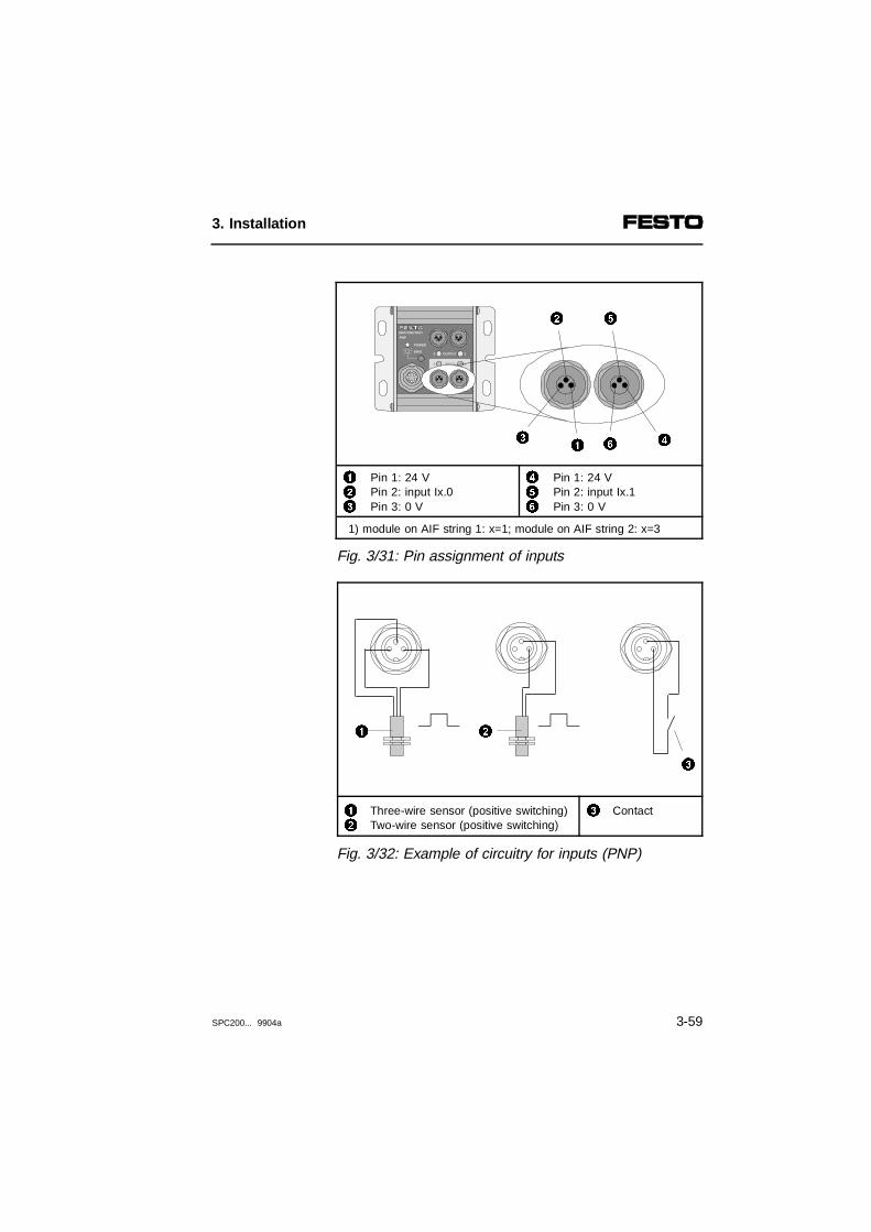
123
Pin 1: 24 VPin 2: input Ix.0Pin 3: 0 V
456
Pin 1: 24 VPin 2: input Ix.1Pin 3: 0 V
1) module on AIF string 1: x=1; module on AIF string 2: x=3
Fig. 3/31: Pin assignment of inputs
12
Three-wire sensor (positive switching)Two-wire sensor (positive switching)
3 Contact
Fig. 3/32: Example of circuitry for inputs (PNP)
POWER
DIAGOUTPUT
PNP
0 1
INPUT/OUTPUT
INPUT0 1
46
5
13
2
2
3
1
3. Installation
SPC200... 9904a 3-59

3. Installation
3-60 SPC200... 9904a

Chapter 4
Commissioning
4. Commissioning
SPC200... 9904a 4-1
Contents
4. Commissioning
4.1 Procedure for commissioning........................................................ 4-54.2 Connecting a single axis system for initial commissioning ........... 4-94.3 Commissioning via the control panel .......................................... 4-164.3.1 Saving the hardware configuration.............................................. 4-164.3.2 Commissioning pneumatic axes.................................................. 4-204.3.3 Instructions on commissioning multi-axis systems...................... 4-38
4. Commissioning
4-2 SPC200... 9904a

This chapter deals with the commissioning of a pneu-matic axis together with the SPC200 by means of con-trol panel type SPC200-MMI-1.
Contents ofthis chapter
Commissioning is described using, as an example, asingle axis system with control via an I/O module. Thebasic method of procedure, as well as the explanationof the I/O control signals, is also relevant for systemsequipped with a field bus module.
You should be familiar with the operating functions ofthe control panel before using it to carry out com-missioning. Detailed information on this can be found inchapter 6.
Further information
The WinPISA manual contains information on com-missioning with WinPISA. Information on commissioningthe field bus or electric axes can be found in the ma-nual for the relevant extension module.
4. Commissioning
SPC200... 9904a 4-3
WARNINGBefore installation and maintenance work switch offthe following in the order specified:1. the compressed air supply2. the load and operating voltages on the SPC200
and, if necessary, the load voltage on the axis interface string.
By doing this you will avoid:
– undesirable movements of connected actuators.
– uncontrollable movements of loose tubing.
– undefined switching states.
CAUTIONThe SPC200 is factory set to certain axis and appli-cation parameters. Before supplying compressed air,these settings must be adjusted to suit your applica-tion and the axes which you are using.
By doing this you will avoid:
– undesirable movements of connected actuators.
4. Commissioning
4-4 SPC200... 9904a
4.1 Procedure for commissioning
Install the components, as described in Chapter 2. Inassembling and installing the pneumatic components,observe the installation recommendations in Chapter 3.In doing so, make provision for a pneumatic emergencystop circuit which will leave your equipment in a safecondition in the event of faults.
Before switching on the compressed air or, where ap-plicable, the power controller for electric axes, you mustfeed information on the prevailing conditions of use andthe type of components in your positioning system tothe SPC200. You should make the necessary settingswith:
• the control panel
• the WinPISA software package
If you use the control panel for commissioning, youmust first familiarise yourself with the control panelfunctions. You will find information on this in Chapter 6.
4. Commissioning
SPC200... 9904a 4-5
Commissioning steps
In order to commission axes, you must first create andsave the desired hardware configuration. The individualaxes and the complete system can then be commis-sioned.
You must carry out the following steps when com-missioning with the control panel:
1. Create the desired hardware configuration.
2. Save the hardware configuraton as the referenceconfiguration (see section 4.3.1).
3. Commission the connected axes (section 4.3.2).
4. Commission the complete system.
When the hardware configuration had been saved, theindividual axes can be configured and commissioned.The following list shows the steps which are necessaryfor commissioning penueumatic axes.
4. Commissioning
4-6 SPC200... 9904a

Commissioning penueumatic axes
The following list contains a summary of the activitiesrequired for commissioning penueumatic axes when thehardware configuration has been saved.
1. Set project-specific parameters.Set all axis, application and configuration par-ameters (see section 4.3.2, step 1).
2. Check tubing (optional).Cappy out a movement test with the aid of the con-trol panel or with WinPISA (see section 4.3.2, step2).
3. Carry out static and, if applicable, dynamic identifica-tion travel. During identification travel, system char-acteristics such as friction, hysteresis, ability to ac-celerate and brake are ascertained and saved (seesection 4.3.2, step 3).
4. If necessary, calibrate the measuring system (onlyfor potentiometer with WinPISA). Calibrationequalizes tolerances between the ascertained posi-tion and the actual postion as a result of technicalfactors in the system (see section 4.3.2, step 4).
5. Move the axis manually (optional). In this way youcan check the functioning of the controller as well asthe effectiveness of the set software end positions(see section 4.3.2, step 5).
4. Commissioning
SPC200... 9904a 4-7

6. Enter the test program (see section 4.3.2, step 6).
7. Set the operating mode and starting programs (seesection 4.3.2, step 7).
8. Test the programs in single-step mode or in con-tinuous mode. Observe here the positioning beha-viour of the axis (see section 4.3.2, step 7).
Commissioning the complete system
When all the axes are ready for operation, you canstart commissioning the complete positioning system.The steps required depend on the equipment fitted inthe positioning system.
The next section deals with the commissioning of apneumatic axis using the example of a single-axis sys-tem without a field bus module.
4. Commissioning
4-8 SPC200... 9904a
4.2 Connecting a single axis system for initial commissioning
With some commissioning steps, the control signalsENABLE, START and STOP are required for controllingthe axes.
If a fieldbus module is installed
WinPISA provides a test mode. In this test mode, youcan manipulate all the inputs and outputs without theseactually being switched.
The status of the READY output and of the ACK out-puts (ACK_A, ACK_B, only in record select mode) usedby the system, is continually updated by the operatingsystem and cannot therefore be influenced.
If a fieldbus module is not installed
If a fieldbus module is not installed, the control signalswill be triggered via the first installed I/O module. Thefollowing connection diagram shows the circuitry re-quired in this case.
4. Commissioning
SPC200... 9904a 4-9
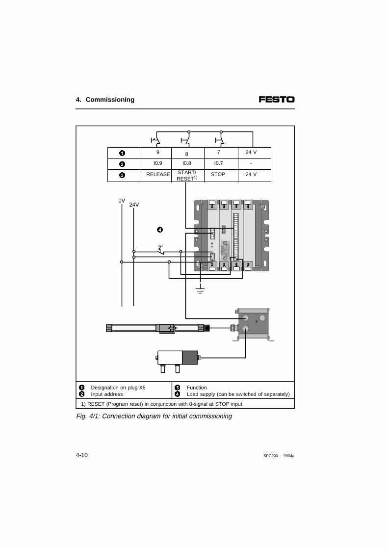
12
Designation on plug X5 Input address
34
FunctionLoad supply (can be switched of separately)
1) RESET (Program reset) in conjunction with 0-signal at STOP input
Fig. 4/1: Connection diagram for initial commissioning
4
9
RELEASE
I0.9
7
STOP
I0.7
8
START/RESET1)
I0.8
24 V
24 V
-2
1
3
4. Commissioning
4-10 SPC200... 9904a

CAUTION• Leave the compressed air supply switched off.• The SPC200 is factory set to certain axis and
application parameters. Before you apply com-pressed air you must adjust these settings to yourapplication and to the axes which you are using.
By doing this you will avoid:
– undesired movements of the connected actuators.
Wire up the components as shown in Fig. 4.1. For thesake of clarity, not all earthing measures are shown.
PLEASE NOTEIncorrect or missing earth connections can cause breakdowns. You should therefore always carry outthe earthing measures described in Section 3.3.1.
4. Commissioning
SPC200... 9904a 4-11
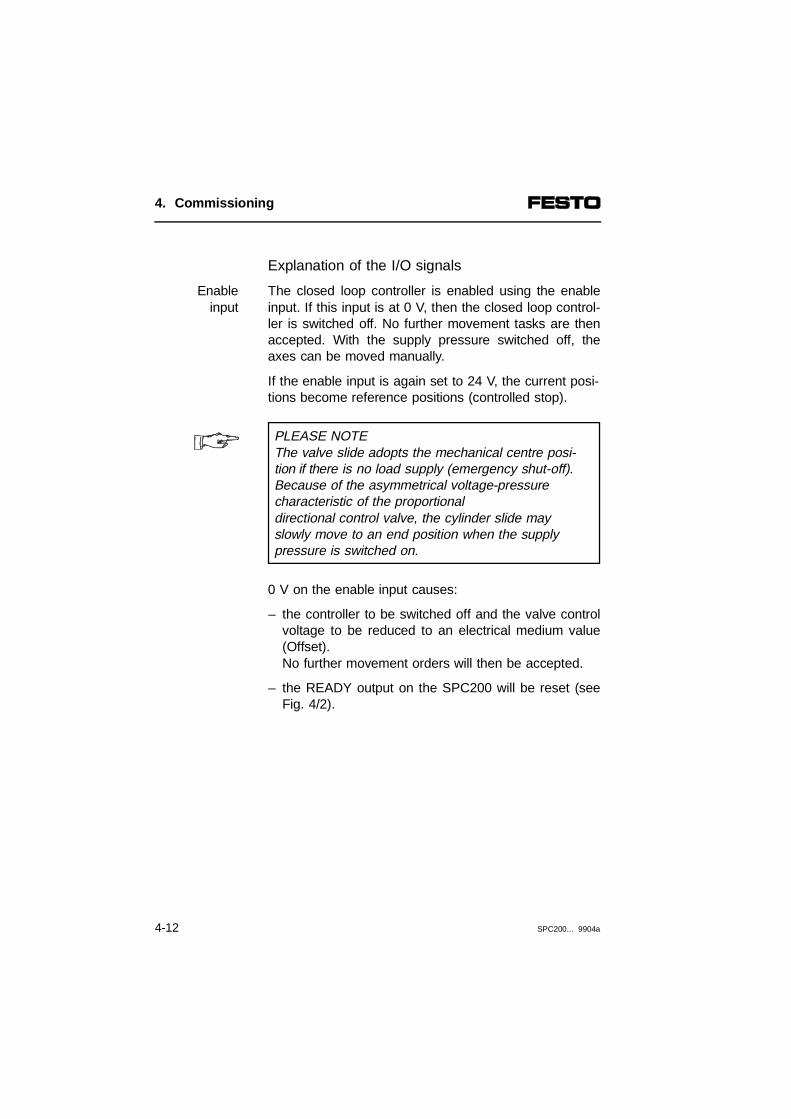
Explanation of the I/O signals
The closed loop controller is enabled using the enableinput. If this input is at 0 V, then the closed loop control-ler is switched off. No further movement tasks are thenaccepted. With the supply pressure switched off, theaxes can be moved manually.
Enableinput
If the enable input is again set to 24 V, the current posi-tions become reference positions (controlled stop).
PLEASE NOTEThe valve slide adopts the mechanical centre posi-tion if there is no load supply (emergency shut-off).Because of the asymmetrical voltage-pressurecharacteristic of the proportionaldirectional control valve, the cylinder slide mayslowly move to an end position when the supplypressure is switched on.
0 V on the enable input causes:
– the controller to be switched off and the valve controlvoltage to be reduced to an electrical medium value(Offset).No further movement orders will then be accepted.
– the READY output on the SPC200 will be reset (seeFig. 4/2).
4. Commissioning
4-12 SPC200... 9904a

123
ENABLE input on the SPC200READY output on the SPC200Reaction time max. 10 ms
4 Reaction time of the SPC200- without stepping motor module: max. 10 ms- with stepping motor module: max. 2 sec.
1 = 1-signal = 24 V; 0 = 0-signal = 0 V
Fig. 4/2: Time diagram of enable signal
This status is cancelled when there is a 1-signal at theENABLE input. The READY output is then setautomatically. If the output supplies a 1-signal, the pro-gram sequence can be started or continued.
Processing of the current NC record can be stoppedusing the Stop input. A positioning process in progresswill be interrupted. The current positions will becomereference positions (controlled stop).
Stop input
The stop status is cleared by:
1. applying 24 V to this input.
2. re-starting the run, e.g. with a rising pulse edge atthe start input.
2
10
10
1
43
4. Commissioning
SPC200... 9904a 4-13

This output supplies a 1-signal, if the system is readyfor operation. 0 V at this output indicates that there is asystem or positioning error, or the enable is missing.
READYoutput
Switch on power supply
WARNINGLeave the compressed air supply switched off. If thecompressed air is on, the connected actuators canexecute sudden equalising movements when the power supply is switched on.Make sure that no one can reach into the range ofmovement of the moving object and that noprotruding objects are in the way.
– Switch on the power supply to the SPC200 and theload supply.
After applying the supply voltage, the SPC200 will auto-matically carry out an internal test. If the control panelis plugged in, it will, in the event of an error, display thecurrent error number (see Section 8.2). When thepower supply is switched on the first time, the followingerror code may be shown:
ERRORNO. 00004001
In this case, neither the actual configuration of theSPC200 nor the configuration on the axis interfacestring are the same as the saved reference configura-tion. Proceed as described in section 4.3.1 under Savehardware configuration.
4. Commissioning
4-14 SPC200... 9904a
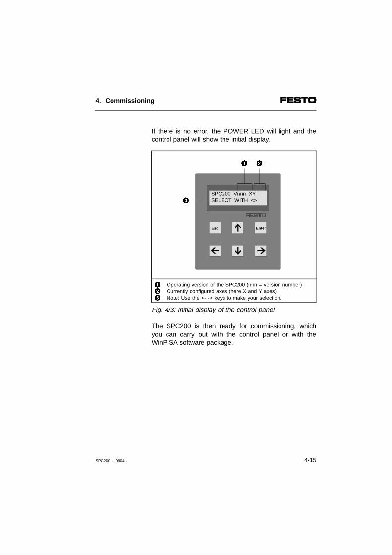
If there is no error, the POWER LED will light and thecontrol panel will show the initial display.
123
Operating version of the SPC200 (nnn = version number)Currently configured axes (here X and Y axes)Note: Use the <- -> keys to make your selection.
Fig. 4/3: Initial display of the control panel
The SPC200 is then ready for commissioning, whichyou can carry out with the control panel or with theWinPISA software package.
EnterEsc
SPC200 Vnnn XYSELECT WITH <>
1 2
3
4. Commissioning
SPC200... 9904a 4-15

4.3 Commissioning via the control panel
If you wish to carry out commissioning with the controlpanel, you should first make yourself familiar with thefunctions of the control panel. For this, leave the com-pressed air supply switched off. Section 6.1.1 providesan overview of the menu system on the control panel.Then proceed as follows:
4.3.1 Saving the hardware configuration
When the SPC200 is switched on, it assigns the axisidentification to the connected axes one after the other.If modifications are made later to the axis configuration,the axis identifications will be reassigned. In this case,all the user data entered, such as parameters, pro-grams and the position list, will become invalid.
CAUTIONIn this case, all data entered will be reset as at de-livery or deleted when the hardware configuration issaved. Always create first the correct hardware con-figuration. Save the hardware configuration before en-tering data and programs.
With WinPISA you can read out programs and configu-ration data from the SPC200 and save them in anarchive, if required.
4. Commissioning
4-16 SPC200... 9904a

The SPC200 makes a comparison during the start-upphase to see if the current hardware configuration is thesame as the saved reference configuration. The mo-dules installed as well as the string assignment arechecked here.
A fixed I/O address range is assigned to every I/O mo-dule on the axis interface string. An axis identifier isassigned to every axis interface and every steppingmotor indexing module or the axis connected to thismodule.
To prepare for commissioning you must create andsave the desired hardware configuration.
Saveconfiguration
The SPC200 is prepared at the factory for automaticallysaving the current hardware configuration during thefirst starting phase. If you have connected the modulesto the axis interface string correctly before switching onthe first time, it will not be necessary to save the hard-ware configuration manually.
4. Commissioning
SPC200... 9904a 4-17
If the actual configuration deviates from the saved refer-ence configuration, proceed as follows:
1. Check that all modules are fitted, that all the mo-dules on the axis interface string are correctly con-nected and that the CP cable is secured correctlywith the union nut. Make sure that the power unithas sufficient output.
2. Now switch on the operating voltage. The statusLEDs on the modules will then light up. If the currenthardware configuration is not the same as the con-figuration saved, an appropriate error message willappear (error code 0000 4001).
3. Check that all the status LEDs light up. These indi-cate that the modules have been recognized cor-rectly.
If required, you can ascertain the actual configurationrecognized during the starting phase by entering thecommand ACTUAL CONFIG. in the menu CONFIG.SYSTEM (see section 6.2).
4. If the actual configuration recognized is not what youwish, switch off the power supply and create thedesired configuration.
5. If the actual configuration recognized is what youdesire, press any key to ackknowledge the errormessage. The basic setting will then be shownagain.
4. Commissioning
4-18 SPC200... 9904a

6. Select the command SET CONFIGUR. in the menuCONFIG. SYSTEM and press the Enter key.
SET CONFIGURSAVE CONFIGUR ?
7. Press the Enter key in order to save the actual con-figuration as the reference configuration.
8. If modifications have been made to the axis configu-ration, the following message will be shown.
RESTORE FACTORYSETTINGS ?
PLEASE NOTEThis message indicates that all the data will be resetto the delivery status. All data and programs enteredwill therefore be lost.
9. Press the ESC key in order to discontinue. Or pressthe keys Enter in order to delete all the data in theSPC200 and to save the hardware configuration.
When the actual hardware configuration is saved, theactual configuration will become the reference configu-ration. The control panel will then again show the basicsetting.
4. Commissioning
SPC200... 9904a 4-19

4.3.2 Commissioning pneumatic axes
When you have created and saved the desired hard-ware configuration, you can commission pneumaticaxes as follows:
Setting project-specific parametersStep 1
Enter all project-specific parameters. These include:
Project-specific parameters Menu on control panel
Axis parameters AXIS PARAM.
Application parameters APPLIC. PARAM.
System configuration data CONFIG. SYSTEM
Leave the supply pressure switched off and proceed asdescribed in Section 6.2 "Setting project-specificparameters".
When the SPC200 is commissioned the first time,there must be a rising edge at the Enable input forcontroller enable after the project-specific parametershave been set. The controller is then enabled with a1-signal, providing there is no system error.
4. Commissioning
4-20 SPC200... 9904a

Checking the axis tubing (optional)Step 2
Check the tubing of the axes. In addition to a visualcheck (see Section 3.2.2) or a check with the aid ofWinPISA you can also use the control panel. For this,the command MOVEMENT TEST is available in theTEST/DIAG. menu.
During the movement test you can alter the valve con-trol voltage. With the supply pressure switched off, thereaction of the valve spool can be observed in the view-ing window of the valve and in this way the operabilityof the valve can be checked.
Control signals required:1-signal at ENABLE, STOP and READY.
CAUTIONDuring the movement test the closed loop controlleris switched off. Consequently the software end posi-tions set by the application parameters areineffective.Carry out the movement test with the supply pres-sure switched on if possible without work load andtool load and with a low supply pressure of not morethan 3 bar.
By doing this you will avoid:
– damage to the axis in the event of operating errors.
4. Commissioning
SPC200... 9904a 4-21

Proceed with the movement test as follows:
1. If necessary, remove the work load and tool load.The mass with which movement is made should beas low as possible, in order to keep the accelerationforces low.
2. Set a pressure of a max. 3 bar and switch on thesupply pressure.
3. Select the submenu AXIS in the menu TEST/DIAG.and press the Enter key.
TEST/DIAG. AXISX:
4. The cursor is positioned at the axis identifier. Selectthe desired axis with the keys ↑ ↓. (here X) andpress the Enter key. The first command in the sub-menu AXIS will then be shown.
TEST/DIAG. AXISJOG AXIS >
5. Now select the command MOVEMENT TEST withthe keys ← →.
TEST/DIAG. AXISMOVEMENT TEST >
4. Commissioning
4-22 SPC200... 9904a

6. Then press the Enter key. After this, the valve test isswitched on. This will set the valve voltage to 5volts. The current valve voltage will be shown imme-diately after the axis symbol.
MOVEMENT TESTX:05.00 +0.01 ?
7. The valve voltage can be raised or lowered in 0.01volt steps. Insert the desired sign with the ↑ ↓ keys.
Control voltage Direction of movement
> 5 volts negative (towards the cylinder basepoint)
< 5 volts positive
In order to overcome the static friction, the control volt-age must be raised or lowered appropriately. The valvevoltage will then be raised or lowered in steps by 0.01volt. If you press the ESC key, the control voltage willbe reset to 5.0 volts.
8. Hold the ENTER key pressed down until the slidestarts to move. Press the ESC key in order to stopthe slide.
Check the direction of movement of the slide during themovement test (see under 7). Correct the tubing con-nections if the slide does not move in the appropriatedirection (see also section 3.2.2). By pressing the ESCkey several times, you can return to the initial display.
4. Commissioning
SPC200... 9904a 4-23

Carrying out identification travelStep 3
PLEASE NOTE The positioning behaviour will probably be bad with-out identification travel. If the axis parameters, the fit-ting position and the supply pressure are modified,the latter by more than 1 bar, the data ascertainedduring identification will be lost. In these cases, there-fore, new identification travel is necessary.
During identification travel, characteristic values of thesystem are ascertained and saved. Before identificationtravel can be carried out, the positioning system mustbe ready for operation.
4. Commissioning
4-24 SPC200... 9904a

A distinction is made here between two types of systemidentification:
Types Description
Staticidentification
In static identification, parameters whichaffect the behaviour of the system at thebeginning and end of a movement aredetermined. These include static friction ofthe cylinder and the valve properties in theregion of the mid position (valvehysteresis).
Dynamicidentification- with work load- without work load
In dynamic identification, the maximum attainable speed as well as theacceleration and decelaration capacity ofthe drive system are determined. To useaxes which are to travel at maximumspeed (NC command G00), thisidentification must first be carried out. Ifconsiderable modification to the massoccurs during operation, it should becarried out both with and without work load.
In order to guarantee good positioning, always carry outthe static and at least one dynamic identification.Dynamic idnetification is also a requirement for the NCcommand G00.
If your compressed air supply does not reliably fulfil therequirements (tolerance of ± 1 bar in operation), pleaserefer to the instructions in section A.3.1.
4. Commissioning
SPC200... 9904a 4-25

It is necessary to carry out the static identification dur-ing initial commissioning and when components havebeen exchanged. The dynamic identification is necess-ary for initial commissioning, when components havebeen exchanged as well as when the drive configura-tion has been modified (fitting position, tubing, or supplypressure).
Control signals required:1-signal at ENABLE, STOP and READY.
CAUTIONIncorrect axis and parameters can lead to collisionduring identification movements. This applies espe-cially to the axis length, the fitting offset and the soft-ware end positions.
WARNINGIn the course of the dynamic identification an axis ofthe system will be set in motion at the highest ac-celeration and speed. Make sure that:- the complete positioning range of the axis is free- the correct axis and application parameters are set.
4. Commissioning
4-26 SPC200... 9904a

Carry out the identification run as follows:
1. Ensure that the tubing for the positioning system islaid correctly (see Step 2, movement test).
2. Set the compressed air supply to the pressuredesired for operation.Standard setting = 6 bar.
3. Select the submenu AXIS in the menu TEST/DIAG.and press the Enter key.
TEST/DIAG. AXISX:
4. The cursor is positioned at the axis identifier. Selectthe desired axis with the keys ↑ ↓ (here X) andpress the Enter key. The first command in the sub-menu AXIS will then be shown.
TEST/DIAG. AXISJOG AXIS >
5. Now select the command IDENTIFICATION with thekeys ← → .
TEST/DIAG. AXISIDENITFICATION >
4. Commissioning
SPC200... 9904a 4-27
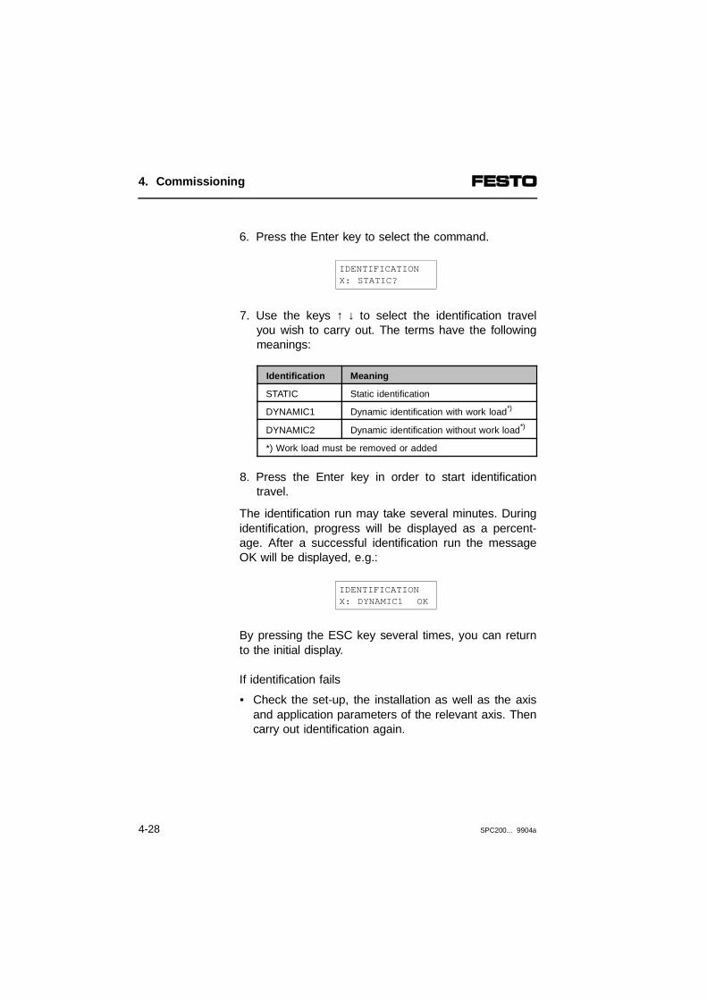
6. Press the Enter key to select the command.
IDENTIFICATIONX: STATIC?
7. Use the keys ↑ ↓ to select the identification travelyou wish to carry out. The terms have the followingmeanings:
Identification Meaning
STATIC Static identification
DYNAMIC1 Dynamic identification with work load*)
DYNAMIC2 Dynamic identification without work load*)
*) Work load must be removed or added
8. Press the Enter key in order to start identificationtravel.
The identification run may take several minutes. Duringidentification, progress will be displayed as a percent-age. After a successful identification run the messageOK will be displayed, e.g.:
IDENTIFICATIONX: DYNAMIC1 OK
By pressing the ESC key several times, you can returnto the initial display.
If identification fails
• Check the set-up, the installation as well as the axisand application parameters of the relevant axis. Thencarry out identification again.
4. Commissioning
4-28 SPC200... 9904a
Calibrating the measuring system(optional with WinPISA)
Step 4
Calibration smooths out system-related toleranceswhich may arise in determining the current position. Inthis way the electrically-determined position values arematched to the actual measurements.
Carry out the calibration when you want to ensure orimprove the absolute positioning accuracy.
4. Commissioning
SPC200... 9904a 4-29

Moving the axis with the control panel (optional)Step 5
Control signals required:1-signal at ENABLE, STOP and READY.
You can move the axis manually with the commandJOG AXIS in the menu TEST/DIAG. Proceed as fol-lows:
1. Select the submenu AXIS in the menu TEST/DIAG.and press the Enter key.
TEST/DIAG. AXISX:
2. The cursor is positioned at the axis identifier. Selectthe desired axis with the keys ↑ ↓ (here X) andpress the Enter key. The command LOG AXIS inthe submenu AXIS will then be shown.
TEST/DIAG. AXISJOG AXIS >
3. Press the Enter key to select the command. The se-lected axis and the current positioning mode willthen be shown.
JOG AXISX: CONT
4. Commissioning
4-30 SPC200... 9904a
4. Select the desired movement mode with ↑ ↓ . Themeaning of the modes is as follows:
Movement mode Meaning
CONT Move continuously
STEP Move in steps twice the set positioning tolerance
JOG AXISX: STEP
5. Press the enter key to activate the movement modee.g.
JOG AXIS STEPX:+0100.00 +
6. Set the desired direction of movement with ↑ ↓ .
7. With movement mode STEP:Press the enter key to move one step.With movement mode CONT:Hold enter key pressed down whilst movement iscarried out.
By pressing the ESC key several times, you can returnto the initial display.
4. Commissioning
SPC200... 9904a 4-31

Possible problems
Cause Remedy Remarks
Slide moves intoan end position
The control direction isnot the same as the direction of movementof the slide.
Swap the connectingtubing on the proportional directional control valve.
See also section 3.2.2
Measuring system ormeasuring systemcable defective.
Replace measuringsystem or measuringsystem cable*).
First checkwithMOVEMENTTEST
The slide oscillates arounda position
The axis or applicationparameters are incorrect.
Correct parameters. See section 6.2
The control panelshows an errornumber
See section 8.2 Rectify error See section 8.2
The slide doesnot move
Valve cable is defective Check cable *) See also section 3.2.2
No supply pressure Switch on compressedair or check tubing.
See also section 3.1
The closed loop controller is switchedoff because there isno ENABLE signal.
Apply 1-signal to theENABLE input
See also section 4.2
System has stopped. Apply 1-signal to theSTOP input (I0.7).
See also section 4.2
Proportional directionalcontrol valve is defective.
Replace the proportional directional control valve.
First checkwithMOVEMENTTEST
*) Check and replace if necessary (see also chapter 8).
4. Commissioning
4-32 SPC200... 9904a
Entering the test programStep 6
In order to avoid unnecessary error messages duringthe starting phase, programs 0 and 1 have alreadybeen created at the factory. They each contain NC rec-ord N000 with the command M30 (Program end).
N000 M30
Select, therefore, the command MODIFY PROGRAM ifyou wish to use program number 0 or 1 for your testprogram.
Enter a short test program, e.g.:
N000 G02 ... X+100 FX50N001 G02 ... X+150 FX90N002 M30
Adapt the position specifications (X+100, Y+150) toyour requirements, where necessary.
Instructions on programming with the control panel canbe found in section 6.3.
4. Commissioning
SPC200... 9904a 4-33
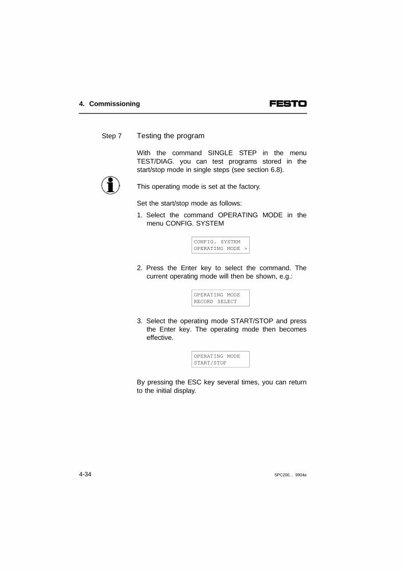
Testing the programStep 7
With the command SINGLE STEP in the menuTEST/DIAG. you can test programs stored in thestart/stop mode in single steps (see section 6.8).
This operating mode is set at the factory.
Set the start/stop mode as follows:
1. Select the command OPERATING MODE in themenu CONFIG. SYSTEM
CONFIG. SYSTEMOPERATING MODE >
2. Press the Enter key to select the command. Thecurrent operating mode will then be shown, e.g.:
OPERATING MODE RECORD SELECT
3. Select the operating mode START/STOP and pressthe Enter key. The operating mode then becomeseffective.
OPERATING MODE START/STOP
By pressing the ESC key several times, you can returnto the initial display.
4. Commissioning
4-34 SPC200... 9904a

Test the program in individual steps as follows:
Control signals required:1-signal at ENABLE, STOP and READY.
1. Select the submenu SYSTEM in the menuTEST/DIAG. and press the Enter key. The com-mand SINGLE STEP will then be shown in the sub-menu SYSTEM (SYS.).
TEST/DIAG. SYS.SINGLE STEP >
2. Press the Enter key to select the command.
SINGLE STEPP00
3. Use the cursor keys to set the program number ofthe test program and press the Enter key. Therecord number of the first NC record will then beshown.
SINGLE STEPP00 N000
4. Press the Enter key to start the NC record. The NCrecord will then be processed. The current recordnumber will be shown in the bottom line.
4. Commissioning
SPC200... 9904a 4-35

5. Repeat point 4 if you wish to start the NC recordshown.
By pressing the ESC key several times, you can returnto the initial display.
4. Commissioning
4-36 SPC200... 9904a

Determining the starting program
In order to test a program in "normal" mode, you mustdetermine it as a starting program (see menu CONFIG.SYSTEM, command DEFINE TASKS). You can start aprogram defined as a starting program with the STARTinput or with the command START SYSTEM in themenu SYSTEM CONTROL.
Program 0 is defined as the starting program at thefactory.
PLEASE NOTEWhen defining starting programs observe the instruc-tions in section 7.1.
In order to improve the positioning characteristics, youcan optimize the controller parameters after the com-missioning (see Appendix A).
4. Commissioning
SPC200... 9904a 4-37

4.3.3 Instructions on commissioning multi-axis systems
First commission each axis individually as described inthis chapter.
Please note when using two starting programs that bothparallel running programs together have the outputREADY and the inputs ENABLE, STOP and START/RESET.
Instructions on coordinated and autonomous modes oftwo axes can be found in section 7.1.1.
4. Commissioning
4-38 SPC200... 9904a
Chapter 5
Controlling the SPC200
5. Controlling the SPC200
SPC200... 9904a 5-I

Contents
5. Controlling the SPC200
5.1 General instrutions on operation ................................................... 5-45.2 Start/stop mode ............................................................................. 5-95.2.1 Explanation of all I/O signals in start/stop mode......................... 5-115.3 Record select mode..................................................................... 5-175.3.1 Description of all I/O signals in record select mode ................... 5-22
5. Controlling the SPC200
5-2 SPC200... 9904a

The SPC200 offers the two following operating modesfor processing the saved NC programs:
Contents ofthis chapter
– start/stop mode
– record select mode
The functions of the digital inputs and outputs as wellas those of the permitted NC commands depend on theoperating mode set. This chapter explains how to con-trol the SPC200 in the operating modes mentioned.Examples of I/O circuitry are shown for controlling theSPC200 via an I/O module. All the I/O control signalsas well as their time behaviour are described.
Information on the coordinated and autonomous oper-ation of axes with an SPC200 can be found in chapter 7.
Furtherinformation
Special instructions on operation with the field bus orthe operation of electric axes can be found in the ma-nual for the relevant extension module.
5. Controlling the SPC200
SPC200... 9904a 5-3
5.1 General instrutions on operation
Operating modes of the SPC200
In the start/stop operating mode the SPC200 is capableof controlling positioning tasks automatically. Any syn-chronisation necessary with externally controlled pro-cesses will be supported by the "Programmed stop"(command M00).
Start/stop
The record select operating mode supports the closecoupling of the SPC200 with a host PLC/IPC. If controlis via an I/O module, 32 NC records of the fixed startingprograms can be accessed via 5 digital inputs. In thisoperating mode only positioning commands, positioningconditions and commands for setting the quality classare supported.
Recordselect
In both operating modes the SPC200 can process twoprograms running in parallel. Coordinated and autono-mous operation of two work stations with one SPC200is then possible.
Enter the desired operating mode and the desired start-ing program on the control panel using the CONFIG.SYSTEM menu.
Setting theoperating
mode
5. Controlling the SPC200
5-4 SPC200... 9904a

1 Dependent on error (see chapter on diagnosis)
Fig. 5/1: SPC200 switch-on procedure
Switch on
Switch on POWER LEDSwitch on ERROR-LED
Initialising andself-test (max. 10 s)
error?
ERROR LED lights orflashes
No
No
Yes
Yes
Systemenable?
(I0.9)
SPC200 is ready foroperation
Set Starting programERROR LED goes out
1
READY output is setClosed loop controller is switched on
Current position = Reference position (controlled stop)
5. Controlling the SPC200
SPC200... 9904a 5-5

If there is a 1-signal at the ENABLE input, the lack ofload voltage will cause an error message. Switch on theload voltage before setting ENABLE to a 1-signal.
When the power supply is switched on, the SPC200carries out initialising and self test. If there is no fault,the set operating mode will be activated and the start-ing programs will be made available. If there is then a1-signal at the ENABLE input:
– the controller will be enabled. The actual positionbecomes the reference position (controlled stop).
– the READY output will be set
This can take a certain amount of time, depending onthe equipment fitted on the system (max. 10 seconds).
If there is a 1-signal at the STOP input and the READYoutput supplies a 1-signal, the program can be pro-cessed or the positioning process started.
5. Controlling the SPC200
5-6 SPC200... 9904a

ENABLE
READY
STOP
START/CLK
12
3
Load voltage should be applied (typ. > 1 Sek.)Reaction time of the SPC200:- without stepping motor module: max. 10 ms - with stepping motor module: max. 2 sec.Debouncing time t ≥ 10 ms
Fig. 5/2: Time behaviour of I/O signals when processing is started
Operating mode Program run or positioning process
Start Continue after STOP signal
Start/stop mode START signal via controlpanel or using START input
START signal via controlpanel or using START input
Record select mode CLK input -
If there is 0 V at the STOP input, a RESET can betriggered by a positive edge on the START input. Thispresets the starting programs for the next start. Allpresettings then become valid again.
0
1
0
1
0
1
0
1
0V
24V
33
2
1
5. Controlling the SPC200
SPC200... 9904a 5-7

Acknowledging a fault
If a fault occurs whilst the program is being processed,the READY output will be reset automatically. When theerror has been eliminated, the error massage can beacknowledged by a START signal. If there are severalerrors at the same time, you must quit each individualerror.
ERROR
ENABLE
READY
STOP
START/CLK
12
34
Time required depends on equipment on system and error (max 10 s)2) Quit error; if there are several errors at the same time, you must quit
each individual error3) Start program or NC recordDebouncing time t ≥ 10 ms
Fig. 5/3: Time behaviour when a fault is acknowledged
If there is no further fault, the READY output will supplya 1-signal again. The program can then be processedfurther or the next NC record can be started.
0
1
0
1
0
1
0
1
0
1
1
32 2
4
4
5. Controlling the SPC200
5-8 SPC200... 9904a

5.2 Start/stop mode
In the start/stop mode the SPC200 is capable of con-trolling positioning tasks on its own. For this purpose,this operating mode provides the following even whenonly one I/O module is used:
– five freely programmable inputs
– three freely programmable outputs
– all NC commands.
With each further I/O module, a further ten freely pro-grammable inputs and eight freely programmable out-puts are available. For special I/O functions directly onthe axis, I/Os can be made available by means of mo-dules on the axis interface string.
In start/stop mode program runs can be controlled bothvia the control panel and via digital I/Os. For loosecoupling with a host PLC/IPC the "Programmed stop"command (M00) is available. With this command theSPC200 program run can be synchronised e.g. withexternally controlled processes.
The following illustration shows the I/O wiring for thecase where it is desired to trigger the control functionsStart, Stop and Enable via an external console. Insteadof a console, a host PLC/IPC can be used for control.
5. Controlling the SPC200
SPC200... 9904a 5-9

1234
Designation on the X5 plug Input address (I = input)FunctionLoad supply (can be switched off separately)
567
Designation on the X6 plugOutput address (Q = output)Function
1) RESET (program reset) in conjunction with 0-signal at STOP input
Fig. 5/4: Example of an I/O wiring for the start/stop operating modewith operation via console
4
4
3
MC_A
Q0.3
7
READY
Q0.7
24 V
24 V
-
0 V
0 V
-65
7
9
ENABLE
I0.9
7
STOP
I0.7
8
START/RESET1)
I0.8
24 V
24 V
-21
3
5. Controlling the SPC200
5-10 SPC200... 9904a
5.2.1 Explanation of all I/O signals in start/stop mode
The pin assignment and I/O addreses of the I/O mo-dules can be found in section 3.3.3 "Field bus ad-dresses" in the manual for the field bus module.
Inputs
Function Description
SYNC_IB Synchronization input for program B(lieke SYNC_IA, but for program B)
SYNC_IA Synchronization input for program AThis input supports synchronization of the SPC200 with externaldevices (e.g. PLC/IPC). With a Programmed stop (command M00),the SPC200 waits for a falling edge at this input before it processesthe next NC record (see Fig. 5.5).
STOP Stop programAn 0-signal at this input causes:- the program and the axes to be stopped- the current position to become the reference position (controlled stop)If there is an 0-signal, a program reset can be triggered by a risingedge at the START input (see under START input).The program will be continued by:1. a 1-signal at this input2. a new start signal (start on the control panel or a rising edge at
the START input).
5. Controlling the SPC200
SPC200... 9904a 5-11

Inputs
Function Description
START/RESET
Start/continue programsA positive edge on this input will cause the program run to be started orcontinued.Requirements:- 1-signal on the STOP input- 1-signal on the ENABLE inputReset the program (RESET)If there is 1-signal on the ENABLE input and 0-signal on the STOP input, aRESET can be triggered by a positive edge on the START input. This causesthe following:- the NC record pointer is reset to 0- the pre-settings G90 and G02 (speed, acceleration and mass load
factor 100 %) as well as the positioning quality class set in the application parameters become valid
- the analogue channel is switched off (M12)- all freely programmable outputs and the SYNC outputs are reset- the set starting programs are made available- any errors are acknowledged.All flags (F), registers (R) and position registers (@) remain unmodified.
ENABLE Closed loop controller enable0-signal on this input causes:- the valve control voltage and the closed loop controller of
all axes to be switched off- the output READY and MC_A/B to be reset.- If you are using a stepping motor:
the ENABLE signal for the power controller will be reset.No further tasks will then be accepted. If a 1 signal is again applied to thisinput:- the outputs READY and MC_A/B will be set again- the valve control voltage and the closed loop controllers of
all axes will be switched on - the current position will become the reference position (controlled stop)- If you are using a stepping motor:
the reference travel must be carried out again.At the next START signal the program run will continue.
5. Controlling the SPC200
5-12 SPC200... 9904a

Outputs
Function Description
MC_B(motioncomplete)
MC output for program B(as MC_A, but for program B)
MC_A(motioncomplete)
MC output for program A24 V at this output shows that a positioning command from program A iscompleted. When the positioning task is completed, a further MC signalwill be output, even if the axis is no longer at the programmed referenceposition (e.g. due to failure of compressed air supply, unstable control etc.).0 V indicates that a positioning process was carried out.
Evaluating the MC signal by PLC.With directly consecutive positioning commands, the MC-signal is perhapstoo short for evaluation by the PLC. The signal can be lengthenedbetween the positioning commands with the NC command G04.
SYNC_OB Synchronisation output for program B(as SYNC_OA, but for program B)
SYNC_OA Synchronisation output for program AIf a 1-signal is applied to the SYNC_IA input in a programmed stop(command M00), a 1-signal at this output indicates the readiness toexecute the next NC record.With a negative edge on the SYNC_IA input the output SYNC_OA is resetand the next NC record processed (see Fig. 5.5).
READY System ready for operationThis output supplies 1-signal, if the system is ready to operate. 0 V at this output indicates that there is a system or position error or thatthere is no ENABLE signal.
5. Controlling the SPC200
SPC200... 9904a 5-13
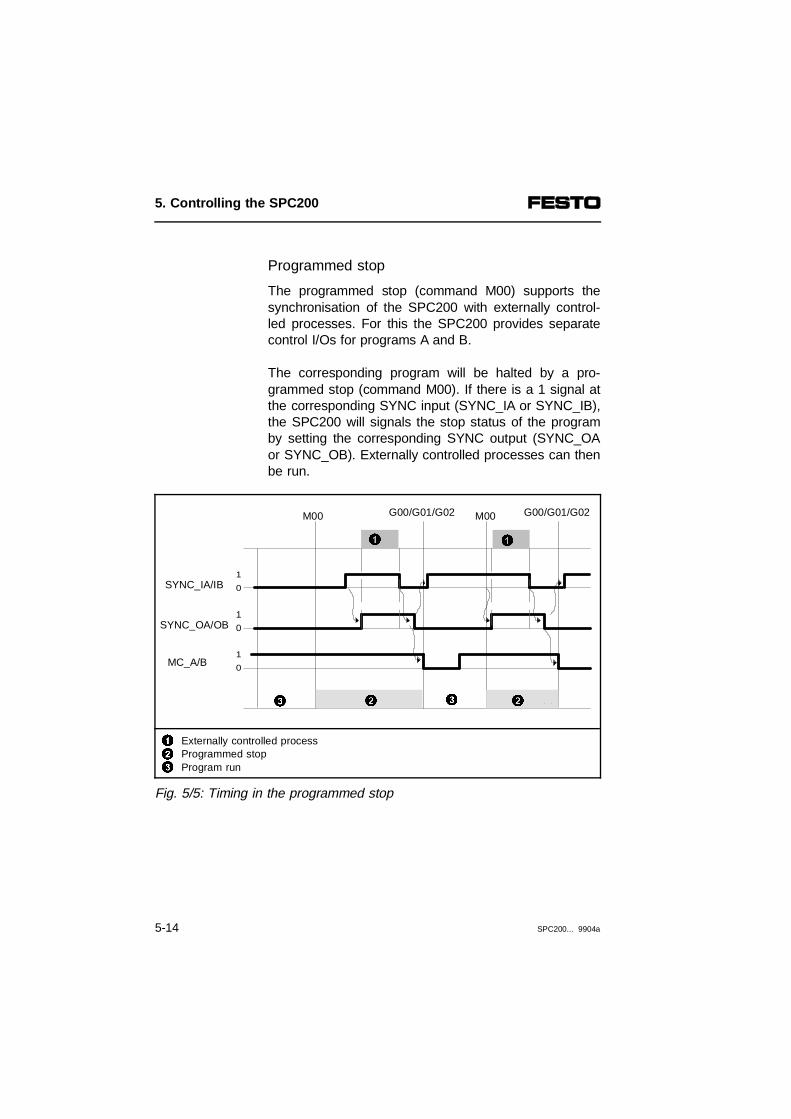
Programmed stop
The programmed stop (command M00) supports thesynchronisation of the SPC200 with externally control-led processes. For this the SPC200 provides separatecontrol I/Os for programs A and B.
The corresponding program will be halted by a pro-grammed stop (command M00). If there is a 1 signal atthe corresponding SYNC input (SYNC_IA or SYNC_IB),the SPC200 will signals the stop status of the programby setting the corresponding SYNC output (SYNC_OAor SYNC_OB). Externally controlled processes can thenbe run.
123
Externally controlled processProgrammed stopProgram run
Fig. 5/5: Timing in the programmed stop
1
0
1
0
1
0
SYNC_IA/IB
SYNC_OA/OB
M00 G00/G01/G02 M00 G00/G01/G02
MC_A/B
11
223 3
5. Controlling the SPC200
5-14 SPC200... 9904a

With a negative edge on the SYNC input the SYNCoutput is reset and the program run continues. The con-tinuation of the program run is represented in Fig. 5.5with the aid of the MC signal.
PLEASE NOTEThe MC output (MC_A/B) is only reset if a position-ing command is being processed (G00, G01, G02and M10).
5. Controlling the SPC200
SPC200... 9904a 5-15
Summary of start/stop mode
In the start/stop operating mode the SPC200 providesfreely programmable inputs and outputs. With the pro-grammed stop (command M00) two programs runningin parallel independently of one another, e.g. through aPLC/IPC, can be synchronised with other processes.
Requirements - Program in program memory- Axis application and system parameters
set correctly- Start/stop operating mode set- 1-signal on the ENABLE and STOP input
set to 24 V
Operation via thecontrol panel
Control functions- Start, Stop, Reset using menu
SYSTEM CONTROL on the control panel
Operation usingI/O
Control functions- Start on positive edge on the
START input- Stop on an 0-signal on the STOP input- Continue program on a 1-signal on the
STOP input and positive edge on theSTART input
- Program reset on an 0-signal on theSTOP input and positive edge on theSTART input
5. Controlling the SPC200
5-16 SPC200... 9904a

5.3 Record select mode
In the record select mode the SPC200 is controlled bya host PLC/IPC. The controlling PLC/IPC passes onpositioning commands to the SPC200 in the form of bi-nary coded record numbers through digital I/Os. TheSPC200 then executes the desired NC record andawaits the next positioning task. In the case of controlvia an I/O module, NC records 0...31 of the startingprograms can be accessed by the controlling PLC/IPC.
Record select mode
Since the running of the NC program is controlled by ahost PLC/IPC, NC commands, which serve forsequencing, are inoperative in this mode of operation.
5. Controlling the SPC200
SPC200... 9904a 5-17

Only purely positioning commands, positioningconditions and commands for setting the quality classare supported. These are:
NCcommand
Descripiton
G00 Move to position at highest possible speed
G01 Move to position at specified speed
G02 Move smoothly to position at specified speed
G08 Acceleration for approach ramp
G09 Acceleration for brake ramp
G60 Precision stop
G61 Quality class
G62 Fast stop
G74 Reference travel
G90 Absolute measurement (pre-setting at program start)
G91 Relative measurement
The following illustration shows an example of I/Owiring for the record select mode.
5. Controlling the SPC200
5-18 SPC200... 9904a
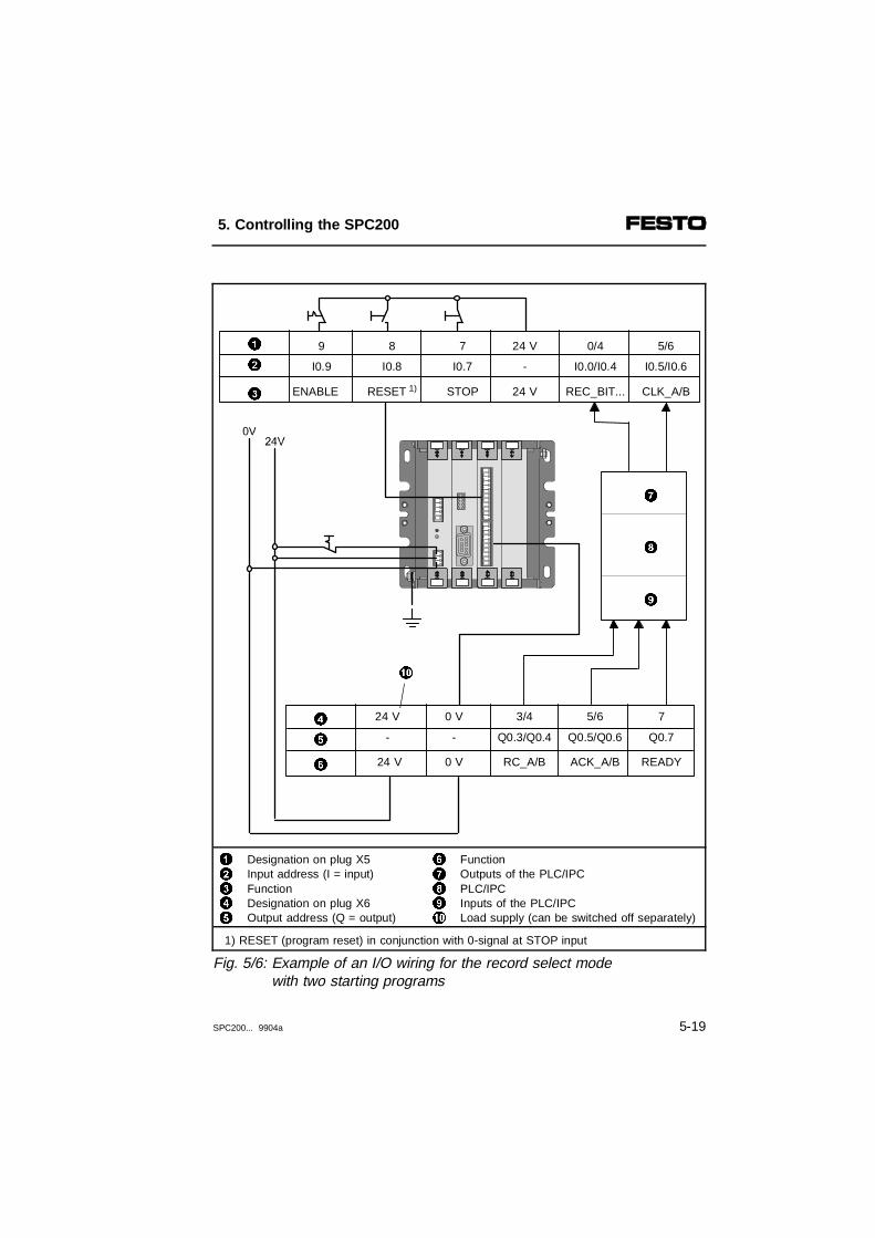
12345
Designation on plug X5 Input address (I = input)FunctionDesignation on plug X6Output address (Q = output)
67890
FunctionOutputs of the PLC/IPCPLC/IPCInputs of the PLC/IPCLoad supply (can be switched off separately)
1) RESET (program reset) in conjunction with 0-signal at STOP input
Fig. 5/6: Example of an I/O wiring for the record select modewith two starting programs
8
9
7
0
24 V
24 V
-
0 V
0 V
-
3/4
RC_A/B
Q0.3/Q0.45
6
4 5/6
ACK_A/B
Q0.5/Q0.6
7
READY
Q0.7
ENABLE
I0.9
7
STOP
I0.7
8
RESET 1)
I0.82
3
0/4
REC_BIT...
I0.0/I0.4
5/6
CLK_A/B
I0.5/I0.6
91 24 V
24 V
-
5. Controlling the SPC200
SPC200... 9904a 5-19

In the Record select mode, positioning tasks in the formof binary coded NC record numbers can be sent to theSPC200 via the inputs REC_BIT... . The record num-bers will be accepted for the corresponding program ona positive edge at the CLK input and acknowledgedwith the ACK signal.
The following illustration shows the signal sequence forcommunicating the relevant I/O signals when issuing amovement task.
1234
Debounce time t ≥ 10 msStatus of the individual input signal depends on the record number required Positioning procedureFrom this moment the PLC/IPC waits for the 1-signal at ouput RC_A/B
Fig. 5/7: Timing chart of the I/O signals in record select mode
10
10
10
10
REC_BIT...
RC_A/B
2
ACK_A/B
CLK_A/B
1
4
3
5. Controlling the SPC200
5-20 SPC200... 9904a

NC record numbers
The desired NC record number, in which the movementorder is stored, is specified through five inputs in binarycoded format. The following NC records can then beaccessed:
Type of control Accessible NCrecord numbers
I/O module (5 inputs: 25 = 32) 0...31
Field bus module (10 inputs) 0 ... 999 1)
1) Maximum permitted number of NC records
The NC records are stored in the SPC200 always be-ginning with NC record 0 and step size 1. If possible,use the same numbering in WinPISA, e.g. with the aidof the numbering function.
The inputs REC_BIT... have the following meaning:
REC_BIT5 REC_BIT4 REC_BIT3 REC_BIT2 REC_BIT1 Designation
2 4 2 3 2 2 2 1 2 0 Value
Input signals NC record number
0 0 0 0 0 0
0 0 0 0 1 1
0 0 0 1 0 2
0 0 0 1 1 3
...
1 1 1 1 0 30
1 1 1 1 1 31
1 1 1 1 1 0 0 1 1 11) 999 1)
1) Control via field bus module
5. Controlling the SPC200
SPC200... 9904a 5-21

5.3.1 Description of all I/O signals in record select mode
The connection assignment and I/O addresses of theI/O modules can be found in section 3.3.3 Field busaddresses in the manual for the field bus module.
Inputs
Function Description
REC_BIT1 Bit 1 for record number ( 20 )
REC_BIT2 Bit 2 for record number ( 21 )
REC_BIT3 Bit 3 for record number ( 22 )
REC_BIT4 Bit 4 for record number ( 23 )
REC_BIT5 Bit 5 for record number ( 24 )
REC_BIT6...REC_BIT10 1)
Bit 5 for record number ( 25 )
Bit 5 for record number ( 29 )
CLK_B Start positioning command from program B(as CLK_A, but for program B)
CLK_A Start positioning order from program A If there is a rising edge at this input, the NC record number at the inputsRECBIT... will be accepted by the SPC200 for program A andprocessed. This will be indicated by the signal ACK_A (see Fig. 5.7).If there is a rising edge at this input, the NC record number at the inputsRECBIT... will be accepted by the SPC200 for program A andprocessed. This will be indicated by the signal ACK_A (see Fig. 5.7).
STOP Stop positioning command0-signal at this input causes:- the axes to be stopped.- the current position to become the reference position
(controlled stop).The positioning order will be resumed by:- applying 1-signal to this input- repeated start of positioning task via the appropriate CLK
input (CLK_A/CLK_B).It is not possible to continue a positioning procedure after a stop signalin this operating mode. If you use NC command G91, a move must bemade to an absolute position (G90) after every stop.
1) REC_BIT6...10 only with control via field bus module
5. Controlling the SPC200
5-22 SPC200... 9904a

Inputs
Function Description
RESET Reset the program (RESET)If there is 1-signal on the ENABLE input and 0-signal on the STOP input, aRESET (program reset) can be triggered by rising edge at the RESETinput. This causes the following:- the NC record pointer is reset to 0- the pre-settings G90 and G02 (speed, acceleration and mass
load factor 100%) as well as the positioning quality class setin the application parameters become valid
- the analogue channel is switched off (M12)- all ACK outputs are reset- the set starting programs are made available- any errors are acknowledged.
ENABLE Closed loop controller enableAn 0-signal at this input causes:- the valve control voltage and the closed loop controllers of
all axes to be switched off- the READY and RC_A/B outputs to be reset.- If you are using a stepping motor:
the ENABLE signal for the power controller will be reset.No further tasks will then be accepted.If a 1-signal is again applied to this input:- the outputs READY and RC_A/B will again be set- the valve control voltage and the closed loop controllers of
all axes will be switched on - the current position will become the reference position
(controlled stop)- If you are using a stepping motor:
the reference travel must be carried out again. With the next CLK signal, the positioning task at the inputs REC_BIT... willbe processed.
5. Controlling the SPC200
SPC200... 9904a 5-23
Outputs
Function Description
RC_B(record com-plete)
NC record from program B concluded(as RC_A, but for program B)
RC_A(record com-plete)
NC record from program A concludedA 1-signal on this output indicates that a positioning task from programA has been completed. When the NC record has been processed,another MC signal will also be output if the axis is no longer at theprogrammed reference position (e. g. because of failure of compressedair supply, unstable control, etc.).An 0-signal indicates that an NC record is being processed.
ACK_B(acknowledge)
Order acknowledged for program B(as ACK_A, but for program B)
ACK_A(acknowledge)
Task accepted for program AThe acceptance of the positioning task from program A is confirmedthrough this output. An 0-signal at this output indicates that the NCrecord number for program A has been accepted (see Fig. 5.7).
READY System ready for operationThis output supplies a 1-signal if the system is ready for operation. 0 Vat this output indicates that there is a system or positioning error or thesystem enable is lacking.
PLEASE NOTEIt is not possible to continue a positioning procedureafter a stop signal in this operating mode. If you useNC command G91, a move must be made to an ab-solute position (G90) after every stop.
5. Controlling the SPC200
5-24 SPC200... 9904a

Summary of record select mode
The record select mode supports close coupling of theSPC200 with a higher-order PLC/IPC.
Requirements - Program in program memory - System parameters entered in
configuration- Record select mode set- 1-signal at ENABLE and STOP input
Operation viacontrol panel
Control function- Stop, reset via menu SYSTEM
CONTROL on control panel
Control throughI/O
Control functions- Select NC record via the REC_BIT...
inputs.- Selected NC record start via CLK input- Stop via STOP input- Program reset by an 0-signal at STOP
input and rising edge at the START input
5. Controlling the SPC200
SPC200... 9904a 5-25

Programing example for record select mode
InputsI0.4...I0.01)
I11.12...I11.82)
NC records of starting program
00000 N000 G00 X100.00 Y100.00
00001 N001 G00 X130.00 Y100.00
00010 N002 G01 X50.00 FX50
... ...
01000 N008 G90 X100.00 Y110.00
01001 N009 G91 X10.00 Y20.00
... ...
10000 N016 G00 X200.00 Y200.00
... ...
11111 N031 G02 X150.00 Y150.00
1) Control via I/O module2) Control via field bus module
Sequence control is carried out exclusively by a higher-order PLC/IPC. With a positive edge at the CLK input,the signals at the inputs I0.0...I0.4 are transferred asNC record numbers, acknowledged by the ACK signaland the NC record is processed.
Only positioning commands (G00, G01 and G02), posi-tioning conditions (G08, G09, G90 and G91) and com-mands for setting the quality class (G60, G61, G62) aresupported.
5. Controlling the SPC200
5-26 SPC200... 9904a
Chapter 6
Operation of the SPC200 via thecontrol panel
6. Operation of the SPC200 via the control panel
SPC200... 9904a 6-1

Contents
6. Operation of the SPC200 via the control panel
6.1 Layout and functions of the control panel ..................................... 6-46.1.1 Moving around the menu system.................................................. 6-86.2. Setting project-specific parameters ............................................. 6-146.3 Editing programs.......................................................................... 6-286.3.1 Adding a new program ................................................................ 6-296.3.2 Editing instructions....................................................................... 6-356.3.3 Instruction set on the control panel ............................................. 6-376.3.4 Editing an existing program......................................................... 6-406.3.5 Deleting a program...................................................................... 6-426.4 Editing the position register ......................................................... 6-436.5 Controlling the program run......................................................... 6-476.6 Display of operands and system states ...................................... 6-496.7 Setting the closed loop control factors ........................................ 6-516.8 Test and diagnostic functions of the control panel ..................... 6-53
6. Operation of the SPC200 via the control panel
6-2 SPC200... 9904a

This chapter deals with the menu and operating func-tions of the control panel type SPC200-MMI-... .
Contents ofthis chapter
All the parameters and operating functions of pneumaticaxes are described in detail and general system opera-ting functions are also described.
Control panel functions for special extension modulessuch as the stepping motor indexer module and thefield bus module are simply listed without any descrip-tion.
Control panel functions for the stepping motor indexermodule and the field bus module can be found in themanual for the relevant product.
Furtherinformation
WinPISA offers the same operating functions and par-ameters as the control panel. Information on this can befound in the manual for WinPISA.
6. Operation of the SPC200 via the control panel
SPC200... 9904a 6-3

6.1 Layout and functions of the control panel
The SPC200-MMI plug-in control panel allows you tocarry out commissioning, programming and diagnosisdirectly on the SPC200. It offers a simple menu struc-ture and a universal keymap. The following illustrationshows the elements of the control panel.
12
Two-line LCD displayESC key
34
ENTER keyCURSOR key
Fig. 6/1: Elements of the control panel
1
2
4
3
6. Operation of the SPC200 via the control panel
6-4 SPC200... 9904a

The two-line LCD display shows all texts in English.Each line displays a maximum of 16 characters. Thetouch-sensitive keyboard consists of 6 keys. With thesekeys you can carry out all of the menu-driven functionsand settings.
Key Description
- Switches back to the next higher level menu- Rejects the current input (breaks off input)- Deletes the current NC record when the cursor in
the editor is on the identifier for NC record number (N)
- Confirms the present menu selection- Adopts the setting made and/or the control function
into the SPC200- Inserts a copy of the current NC record when the
cursor in the editor is on the identifier for NC recordnumber (N)
- Selects the next menu command or parameter- Positions cursor to right or left
- Change setting at current cursor position* Increase or reduce the numerical value* Select axis (set axis symbol)* Select NC command or diagnostic function
6. Operation of the SPC200 via the control panel
SPC200... 9904a 6-5

Switching-on procedure
After switching on the power supply the SPC200automatically performs an internal test. During the brieftest phase, the control panel displays the software ver-sion number of the control panel (here Vn.n).
MMI SPC200 Vn.n
INITIAL TEST
After completing internal testing the SPC200 is ready toprocess user input from the control panel. If an error isdiscovered, the control panel displays the current errornumber (see Section 8.2). If there is no error, the initialdisplay is shown.
6. Operation of the SPC200 via the control panel
6-6 SPC200... 9904a

In the initial display the control panel shows thefollowing message:
123
Operating system version of the SPC200 (nnn = Version number1))Currently configured axis (here X-axis)Prompt line: Make your menu selection with ← →.
1) The point after the main version marker is not shown due tolack of space; nnn indicates n.nn
Fig. 6/2: Initial display on the control panel
Repeated pressing of the ESC key will always lead tothe initial display. A special procedure is necessary forexiting the program editor (see section 6.3.1).
From the initial display, the control panel provides eightmenus to select from. The following illustration providesan overview of the menu structure and the menu com-mands on the control panel:
EnterEsc
SPC200 Vnnn XSELECT WITH <>
1 2
3
6. Operation of the SPC200 via the control panel
SPC200... 9904a 6-7
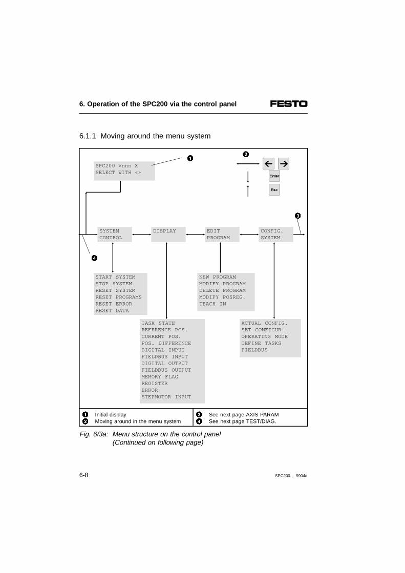
6.1.1 Moving around the menu system
12
Initial display Moving around in the menu system
34
See next page AXIS PARAMSee next page TEST/DIAG.
Fig. 6/3a: Menu structure on the control panel (Continued on following page)
SYSTEMCONTROL
CONFIG.SYSTEM
EDITPROGRAM
START SYSTEMSTOP SYSTEMRESET SYSTEMRESET PROGRAMSRESET ERRORRESET DATA
ACTUAL CONFIG.SET CONFIGUR.OPERATING MODEDEFINE TASKSFIELDBUS
SPC200 Vnnn XSELECT WITH <>
DISPLAY
NEW PROGRAMMODIFY PROGRAMDELETE PROGRAMMODIFY POSREG.TEACH IN
TASK STATEREFERENCE POS.CURRENT POS.POS. DIFFERENCEDIGITAL INPUTFIELDBUS INPUTDIGITAL OUTPUTFIELDBUS OUTPUTMEMORY FLAGREGISTERERRORSTEPMOTOR INPUT
1 2
4
3
6. Operation of the SPC200 via the control panel
6-8 SPC200... 9904a

Pneum. Electr.axis axis
2) 3)
1) Select axis identifiers X, Y, Z or U2) Parameter or function only available with pneumatic axis3) Parameter or function only available with electric axis
12
Previous page CONFIG.SYSTEMMoving around in the menu system
3 see previous page SYSTEMCONTROL
Fig. 6/3b: Menu structure on the control panel (Continuation)
AXISPARAM.
TEST/DIAG.CONTROL.PARAM.
CYL. TYPE2)
CYL. LENGTHCYL. DIAMETER2)
SENSORMEASUREM.2)
APPLIC.PARAM.
GAIN FACTOR2) DAMPING FACTOR2)
FILTER FACTOR2)
POS. TIMEOUT2)
1
2
3
SINGLE STEPINPUT TESTFB. INPUT TEST OUTPUT TESTFB. OUTPUT TESTFLAG TESTREGISTER TEST
JOG AXISMOVEMENT TEST2)
IDENTIFICATION2)
EXIT FROM LIMIT3)
REFER. TRAVEL3)
RESOLUTIONSTART/STOP FREQPOS. BASEPOINTLOWER END POS.UPPER END POS.REF. POSITIONREF. SPEED FAC.MAX. SPEEDMAX. ACCELER.MODE OF REFER.MICRO/HALF STEP
TOOL LOADWORK LOADPRESSUREFITTING POS.FITTING OFFS.POS. BASEPOINTLOWER END POS.UPPER END POS.POS. TOLERANCEQUALITY CLASSMAX. SPEEDMAX. ACCELER.
SYSTEM AXIS
X,Y,Z,U 1)
X,Y,Z,U 1) X,Y,Z,U 1)X,Y,Z,U 1)
6. Operation of the SPC200 via the control panel
SPC200... 9904a 6-9

The menus on the control panel
Menu Description
SPC200 READY SYSTEM CONTROL >
System control:Control functions Start, Stop, Reset
SPC200 READY
DISPLAY >
Display:Operands, System status
SPC200 READYEDIT PROGRAM >
Edit programs:Display and editing of programs andposition register, Teach
SPC200 READYCONFIG. SYSTEM >
Configure system:Determine operating mode andstarting programs,Dispay and accept the hardwareconfiguration
SPC200 READYAXIS PARAM. >
Axis parameters:Display and set (e.g. cylinder length)
SPC200 READYAPLIC. PARAM. >
Application parameters:Display and set (e.g. Project basepoint)
SPC200 READYREGUL. PARAM. >
Controller parameters:Display and set
SPC200 READYTEST/DIAG. >
Testing and diagnosis:Program test, Movement test, etc.
By pressing the ← or → keys you can call up theindividual menus from the initial display one after theother. The name of the menu is shown in the lower line.In addition, the upper line shows the text from the initialdisplay (SPC200...). This informs you that you are inthe first level.
6. Operation of the SPC200 via the control panel
6-10 SPC200... 9904a

In selecting, the upper line will serve to orient you. Itshows, e.g. the menu in which you are located. Thelower line offers the selections which are possible in thecurrent menu. The availability of the selection is indi-cated by the > symbol.
When a selection has been made by pressing the Enterkey, the text in the display scrolls up.
12345
Display from the initial display (first level)AXIS PARAM. menu can be opened with the Enter key AXIS PARAM. menu is openedAxis identifier, select with ↑ ↓.First parameter of selected axis
Fig. 6/4: Functions of the display lines
AXIS PARAM. CYL. TYPE >5
AXIS PARAM. X:
3
4
1
2SPC200 READYAXIS PARAM. >
6. Operation of the SPC200 via the control panel
SPC200... 9904a 6-11

The upper line then shows the previous selection forguidance. The lower line again shows the currentpossible selection or the input field in the lowest level.
In the case of menus which contain axis-specific par-ameters or operating functions, the axis identifier of thefirst axis (X) will be shown when the menu is opened.With multi-axis systems, the desired axis can be se-lected with the keys ↑ ↓. and the Enter key. All the fol-lowing parameters and operating functions refer to theaxis selected.
If, for example, an electric axis is selected, parametersor control functions for electric axes will be shown.
Summary: moving in the menu system
Purpose Press
Confirm current selection and, if applicable,switch to one level below
Different selection in same menu level
Select axis identifier
Discontinue selection and switch to one levelabove
6. Operation of the SPC200 via the control panel
6-12 SPC200... 9904a
In selecting a menu command or parameter proceed asfollows:
1. Press the ESC key repeatedly until the initial displayis shown. The first line of the display then shows thetext SPC200 followed by the version number of theoperating system.
2. Press the ← or → key repeatedly, until the desiredmenu is displayed in the lower line.
3. Press the Enter key. This will open the menu anddisplay the first parameter or the first control functionof the menu.
4. If an axis identifier is offered for selection, select itwith the keys ↑ ↓ and then press the Enter key.
5. If a parameter or an operating function is displayed,you can page through the menu with the keys ← or→, until the desired parameter or command isshown in the bottom line.
6. Press the Enter key to select the command or par-ameter.
How adjustments are made, how programming is car-ried out or how control functions are triggered areshown in the following section.
6. Operation of the SPC200 via the control panel
SPC200... 9904a 6-13

6.2. Setting project-specific parameters
WARNINGIncorrectly set parameters can lead to uncontrolledbehaviour of the connected axes during operation.
The SPC200 must be aware of the conditions of usegoverning your project and the type of componentsused in your positioning system. The necessary settingsshould be made in the following menus:
Menu Description
SPC200 READYAXIS PARAM. >
Axis parameter;Data on the axes to be used
SPC200 READYAPPLIC. PARAM. >
Application parameter;Data on the conditions of use
SPC200 READYCONFIG. SYSTEM >
System configuration;Operating mode, starting programs,hardware configuration
6. Operation of the SPC200 via the control panel
6-14 SPC200... 9904a

Procedure
If you have selected a parameter in a menu by press-ing the Enter key (see Section 6.1.1), the text in thedisplay will scroll up.
12345
AXIS PARAM. menu is openedAxis identifier can be selected, select with ↑ ↓Parameter "cylinder type" can be selected Axis identifier (here X for X axis)Current setting of the X axis (here cylinder type 1)
Fig. 6/5: Functions of the display lines
The upper line then shows the previous selection (hereAXIS PARAM.) for guidance. When entering axis-spe-cific parameters, you can then select the desired axis.In this case the cursor is positioned on the axis identi-fier.
CYL. TYPEX: 1
5
1
2AXIS PARAM. X:
AXIS PARAM. CYL. TYPE >
3
4
6. Operation of the SPC200 via the control panel
SPC200... 9904a 6-15
The appropriate axis must be connected to the SPC200and the current hardware configuration must be saved.
With the keys ↑ and ↓, you can select the axis, theparameters of which you wish to modify. When the axishas been selected, the current parameter setting will beshown in the bottom line.
In order to alter a parameter, position the cursor withthe ← → keys on the desired number of the parameterindicated. The number can now be altered with the ↑ ↓keys. If a parameter value is altered, the character ?will be shown in the lower line.
6. Operation of the SPC200 via the control panel
6-16 SPC200... 9904a

123
Character flashes (here underscored) = current cursor positionCharacter for altering valueNew value was accepted (? no longer shown)
Fig. 6/6: Set parameter value
The symbol ? indicates that the intended setting is ac-cepted into the SPC200 only when the Enter key ispressed. After pressing the Enter key, the ? is deleted.This indicates that the setting was accepted.
The following sections describe the significance of theindividual parameters, which you must match to yourproject.
CYL. TYPEX: 1
CYL. TYPEX: 2 ?
1
CYL. TYPEX: 2 3
2
6. Operation of the SPC200 via the control panel
SPC200... 9904a 6-17

Axis parameters
The axis parameters are configuration parameterswhich describe the configuration, the properties and thecomponents of the axis being used. The axis par-ameters form the basis for parameter ranges of the ap-plication parameters (e.g. possible axis movementspeed).
AXIS PARAMmenu
Axis parameters for pneumatic axes:
When the axis parameters have been modified, newidentification travel may be necessary.
AXIS PARAM menu (axis parameters)
Pneumatic axis
CYL. TYPEX:0
Cylinder type (design) 0...2Enter the type for the cylinder used.0 = Cylinder with piston rod1 = Cylinder without piston rod2 = Rotary actuator
CYL. LENGTHX:+0050.00
Cylinder length 50...3200 [mm]Length of cylinder (see Identification plate).
CYL. DIAMETERX:+0012.00
Cylinder diameter 12...320 [mm]Diameter of cylinder (see Identification plate)
SENSOR LENGTHX:+0050.00
Measuring system length 50...3200 [mm]Length of the measuring system used (see Identification plate)
VALVE TYPEX:0
Valve type (see Identification plate) 0...40 = MPYE-5-M5-010B1 = MPYE-5-1/8-LF-010B2 = MPYE-5-1/8-HF-010B3 = MPYE-5-1/4-010B4 = MPYE-5-3/8-010B
6. Operation of the SPC200 via the control panel
6-18 SPC200... 9904a

Axis parameters for electric axes:
AXIS PARAM menu (axis parameters)
Electric axis
CYL. LENGTHY:+0050.00
Cylinder length 1) 50...3200 [mm]
1) Explanations see manual for stepping motor indexer module type P.BE-SMX-1-...
Application parameters
The application parameters are configuration informa-tion, which describe the conditions of use assigned bythe application.
APPLIC.PARAM
menu
Application parameters for pneumatic axes
The application parameters are an important basis forthe internally ascertained controller parameters. If thefitting position or the supply pressure have been modi-fied, the latter by more than 1 bar, new identificationtravel may be necessary.
APPLIC. PARAM menu (Application parameters)
Pneumatic axis
TOOL LOADX:+0000.00
Tool load 0.1...2000 [kg]In the pneumatic axis the tool load describes the total weight ofthe following constituents:- weight of slide and piston- weight of the fastening plate- tool weightThe maximum permissible tool load depends upon the type ofcylinder used.
WORK LOADX:+0001.00
Work load 0...2000 [kg]Maximum weight of the object to be transported. Recommendation: Use the NC command M37, if you wish towork with different loads.
6. Operation of the SPC200 via the control panel
SPC200... 9904a 6-19
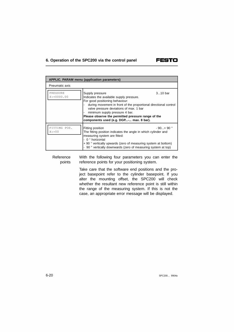
APPLIC. PARAM menu (application parameters)
Pneumatic axis
PRESSUREX:+0000.00
Supply pressure 3...10 barIndicates the available supply pressure. For good positioning behaviour:- during movement in front of the proportional directional control
valve pressure deviations of max. 1 bar - minimum supply pressure 4 bar. Please observe the permitted pressure range of the components used (e.g. DGP...-... max. 8 bar).
FITTING POS.X:+00
Fitting position - 90...+ 90 °The fitting position indicates the angle in which cylinder andmeasuring system are fitted:- 0 ° horizontal+ 90 ° vertically upwards (zero of measuring system at bottom)- 90 ° vertically downwards (zero of measuring system at top)
With the following four parameters you can enter thereference points for your positioning system.
Referencepoints
Take care that the software end positions and the pro-ject basepoint refer to the cylinder basepoint. If youalter the mounting offset, the SPC200 will checkwhether the resultant new reference point is still withinthe range of the measuring system. If this is not thecase, an appropriate error message will be displayed.
6. Operation of the SPC200 via the control panel
6-20 SPC200... 9904a

123
Measuring system basepointCylinder basepointPosition basepoint (Project zero point)
45
Lower software end positionUpper software end position
Fig. 6/7: Reference points
APPLIC. PARAM menu (application parameters)
Pneumatic axis
FITTING OFFS.X:+0000.00
Fitting offset -1600...+1600 [mm]Offset between basepoint of measuring system and cylinderbasepoint.The mounting offset is positive, if the cylinder basepoint lieswithin the range of the measuring system. The mounting offset isnegative, if the cylinder basepoint lies outside the range of themeasuring system.
POS. BASEPOINTX:+0000.00
Position basepoint (Project zero point) 0...+3200 [mm]Indicates the point on the axis to which the positions contained inthe position registers and programs relate. The project basepointrelates to the cylinder basepoint.
4
2 3
5
1
6. Operation of the SPC200 via the control panel
SPC200... 9904a 6-21
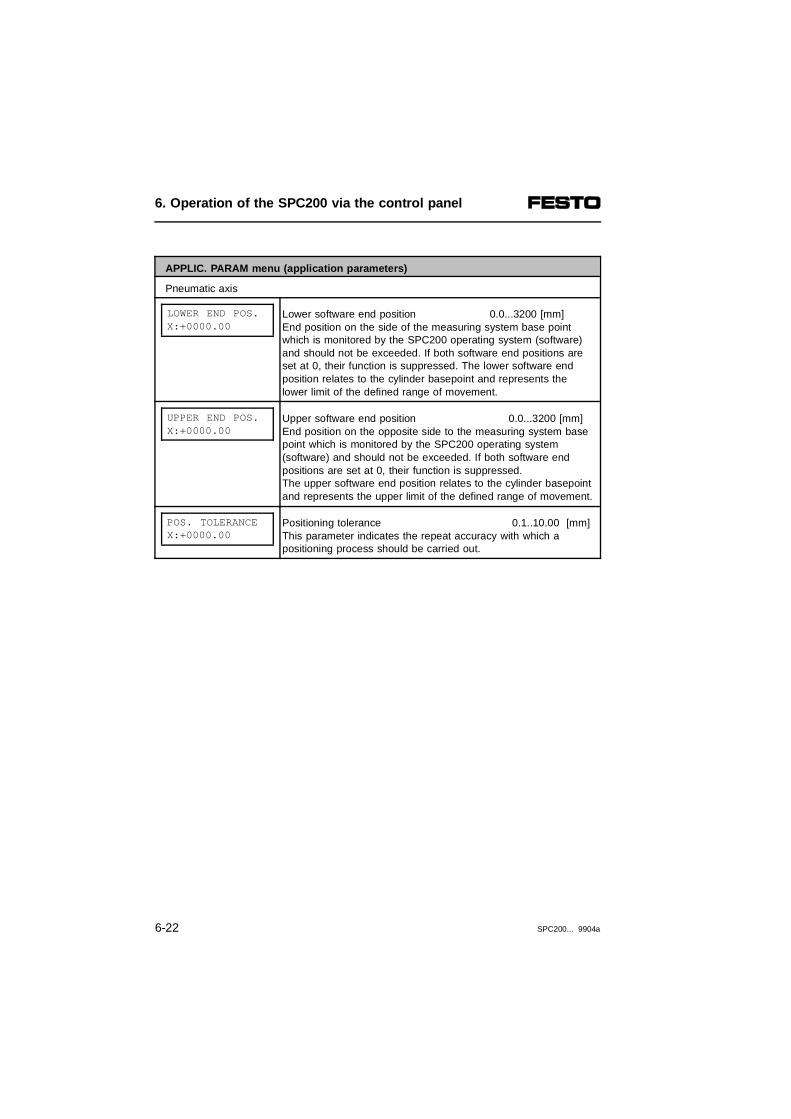
APPLIC. PARAM menu (application parameters)
Pneumatic axis
LOWER END POS.X:+0000.00
Lower software end position 0.0...3200 [mm]End position on the side of the measuring system base pointwhich is monitored by the SPC200 operating system (software)and should not be exceeded. If both software end positions areset at 0, their function is suppressed. The lower software endposition relates to the cylinder basepoint and represents thelower limit of the defined range of movement.
UPPER END POS.X:+0000.00
Upper software end position 0.0...3200 [mm]End position on the opposite side to the measuring system basepoint which is monitored by the SPC200 operating system(software) and should not be exceeded. If both software end positions are set at 0, their function is suppressed.The upper software end position relates to the cylinder basepointand represents the upper limit of the defined range of movement.
POS. TOLERANCEX:+0000.00
Positioning tolerance 0.1..10.00 [mm]This parameter indicates the repeat accuracy with which apositioning process should be carried out.
6. Operation of the SPC200 via the control panel
6-22 SPC200... 9904a

APPLIC. PARAM menu (application parameters)
Pneumatic axis
QUALITY CLASSX:1
Quality class 1...6Describes the conditions under which a movement commandshould be considered as terminated or when the MC (MotionComplete) signal should be issued. Where:1 = Fast stop without damping time2 = Fast stop with damping time3 = Precision stop without damping time4 = Precision stop with damping time5 = Precision stop with terminal speed control6 = Precision stop with damping time and terminal speed controlThe setting established here acts as a default setting on programstart-up. It can be changed in the program with the commandsG61 and G60.
MAX. SPEED+0000.00
Maximum speed 0.1...10.0 [m/s]Maximum speed for the movement with the commands G01 andG02. The speed factor given by the movement commands G01and G02 refer to the maximum speed defined here.
MAX. ACCELER.+0000.00
Maximum acceleration 0.1...100.0 [m/s2]Maximum acceleration for the movements with the commandsG01 and G02. In the movement program a reduced accelerationbased on the maximum acceleration defined here can be set withthe commands G08 and G09.
6. Operation of the SPC200 via the control panel
SPC200... 9904a 6-23

Application parameters for electric axes:
APPLIC. PARAM menu (application parameters)
Electric axis
RESOLUTIONY:+0010.000
Resolution1) 0.100...9999.999 [1/mm]
START/STOP FR.Y:+0500.00
Start-stop frequency1) 1 .. 9999 [Hz]
POS. BASEPOINTY:+0000.00
Project basepoint1) 0.0 .. 3200.0 [mm]
LOWER END POS.Y:+0010.00
Lower software end position1) 0.0 .. 3200.0 [mm]
UPPER END POS.Y:+0090.00
Upper software end position1) 0.0 .. 3200.0 [mm]
REF. POSITIONY:+0010.00
Reference position1) 0.0 .. 3200.0 [mm]
REF. SPEED Y:+0001.00
Reference speed factor1) 0.01 .. 1.00
MAX. SPEEDY:+0000.10
Maximum speed1) 0.1 .. 10.0 [m/s]
MAX. ACCELER.Y:+0000.50
Maximum acceleration1) 0,1 .. 100,0 [m/s2]
MODE OF REFER.Y:0
Mode of reference1) 1 .. 4
MICRO/HALF STEPY:0
Micro/half step1) 0 or 1
1) Explanations see manual for stepping motor indexer module
6. Operation of the SPC200 via the control panel
6-24 SPC200... 9904a

System configuration
Enter the desired type of operation and the starting pro-grams for your system in the CONFIG. SYSTEM menu.
CONFIG.SYSTEM
menu
Description of the individual parameters
CONFIG. SYSTEM menu (configure system)
ACTUAL CONFIGUR.1. AIF
Display current configurationShows the hardware configuration ascertained during startingphase.n. AIF ;1...2 axis interface string (n = 1...2)n. SM ;1...3 stepping motor (n = 1...3) If stepping motor indexer modules are fitted, the selection"n.SM" will show which axis identifer is assigned to the first,second or third stepping motor indexer module.The selection "n.AIF" will show which axis identifiers have been assigned in the starting phase and which modules havebeen recognized on the relevant string. The recognized moduletypes (CP modules) are listed as follows:I = input moduleO = module with outputs or valves I/O = I/O function moduleThe entry "-" means that no module has been recognized.Example 1.AIF AXIS: XY
CP-MOD: -, -, I/OExplanation Two axis interfaces were recognized on the first axis interfacestring in the starting phase. The axis identifiers X and Y wereassigned to these interfaces. An I/O function module was also recognized on the axis interface string.
6. Operation of the SPC200 via the control panel
SPC200... 9904a 6-25

CONFIG. SYSTEM menu (configure system)
SET CONFIGUR.SAVE CONFIGUR.
Save actual configuration as the set configuration Please observe the instructions on procedure in section 4.3.1When the system is started, the SPC200 compares the actualhardware configuration with the saved set configuration.The modules fitted and the string assignment are checked here.With this command, the actual hardware configuration (modulesfitted) and the actual string assignment can be saved as the setconfiguration. If the axis configuration has been modified, thedata already entered is no longer valid and will be reset to thestatus as at delivery or deleted.
OPERATING MODESTART/STOP
Operating mode START/STOP = Start/stop modeRECORD SELECT = Record select modeThe operating mode defines how the sequencing of the SPC200should work. You will find explanations of the operating modes inChapter 5.
DEFINE TASKSTA:P00
Define task program Tn = Task number TA, TBPn = Program number - -/0...99P- - for "no starting program selected" If the cursor is positioned at P, you can switch between P00 andP- - for task B.One SPC200 can control two work stations. In this it supports thecoordinated and autonomous operation of both axes. In the caseof coordinated operation the option of parallel programprocessing is not used. Only one starting program is defined(one active task). This controls both work stations. Inautonomous operation, two starting programs (two active tasks)are defined. Each starting program controls another work station.Further information on coordinated and autonomous operation can be found in Chapter 7.1.1.
6. Operation of the SPC200 via the control panel
6-26 SPC200... 9904a
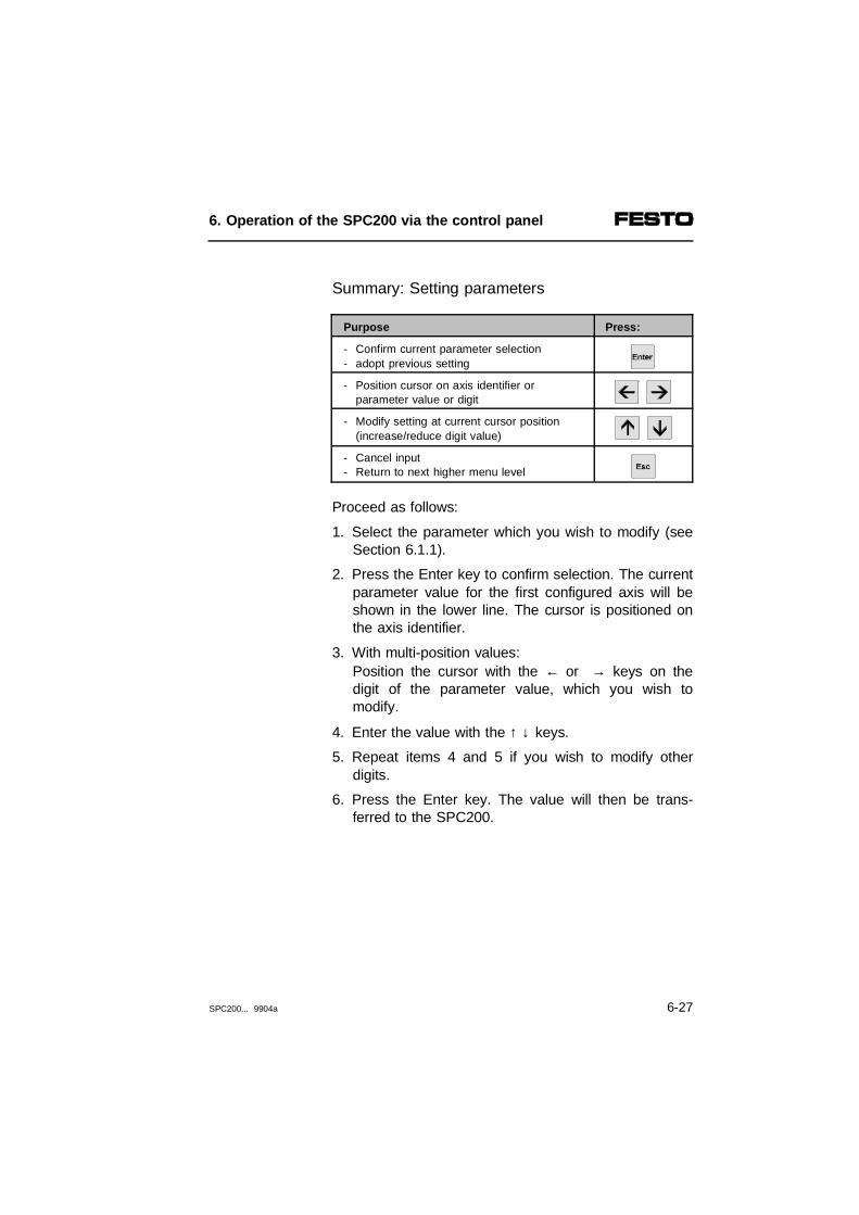
Summary: Setting parameters
Purpose Press:
- Confirm current parameter selection - adopt previous setting
- Position cursor on axis identifier orparameter value or digit
- Modify setting at current cursor position(increase/reduce digit value)
- Cancel input- Return to next higher menu level
Proceed as follows:
1. Select the parameter which you wish to modify (seeSection 6.1.1).
2. Press the Enter key to confirm selection. The currentparameter value for the first configured axis will beshown in the lower line. The cursor is positioned onthe axis identifier.
3. With multi-position values:Position the cursor with the ← or → keys on thedigit of the parameter value, which you wish tomodify.
4. Enter the value with the ↑ ↓ keys.
5. Repeat items 4 and 5 if you wish to modify otherdigits.
6. Press the Enter key. The value will then be trans-ferred to the SPC200.
6. Operation of the SPC200 via the control panel
SPC200... 9904a 6-27

6.3 Editing programs
The control panel provides you with an Editor, whichcan be used to edit both the position register and NCprograms. If your positioning system is fully configured,you can teach the position register with the aid of theTeach functions.
You will find all menu commands for editing NC pro-grams and position registers in the EDIT PROGRAMSmenu.
EDIT PROGRAM menu (for editing programs)
EDIT PROGRAMNEW PROGRAM >
Add new program
EDIT PROGRAMMODIFY PROGRAM >
Modify program
EDIT PROGRAMDELETE PROGRAM >
Delete program
EDIT PROGRAMMODIFY POSRG >
Modify position register
EDIT PROGRAMTEACH IN >
Teach mode(Teach position register)
These commands are explained in the followingsections.
6. Operation of the SPC200 via the control panel
6-28 SPC200... 9904a

6.3.1 Adding a new program
1. In the initial display press the ← or → key re-peatedly, until the EDIT PROGRAM menu is dis-played.
SPC200 READYEDIT PROGRAM >
2. Press the Enter key to open the EDIT PROGRAMmenu. The first command (New Program) will thenbe displayed in the lower line.
EDIT PROGRAM NEW PROGRAM >
3. Press the Enter key to select the command.
NEW PROGRAM PROGRAM NO: 00?
4. Programs 0 and 1 have already been created at thefactory. Use the cursor keys to set the desired num-ber of a new program, e.g.:
NEW PROGRAM PROGRAM NO: 03?
5. Press the Enter key to create the program. After cre-ating the program, you can edit the first NC record.
6. Operation of the SPC200 via the control panel
SPC200... 9904a 6-29

To display an NC record both lines of the display areused. This is treated as a single line of 32 characters.
Please note that in programming multi-axis systems, forreasons of space, only the parameters for the currentlyselected axis are displayed.
The procedure in editing an NC record is explainedbelow using the command G00 (Move to position athighest possible speed) as an example. The appendixcontains a summary of all available NC commands.There is a detailed description of the NC commandstogether with example programs in Chapter 7.
Example: NC record with G00
After a program has been created, the number of theprogram created will be displayed in the first 3 columns(here P03). After this is the NC record number N000.
P03:N000 * *X+0000.00
The cursor stands at identifier N.
1. Press button → to position the cursor at the first NCword of the current NC record (here * for positioningwith saved values).
The desired NC command can be selected with the ↑ ↓keys.
6. Operation of the SPC200 via the control panel
6-30 SPC200... 9904a
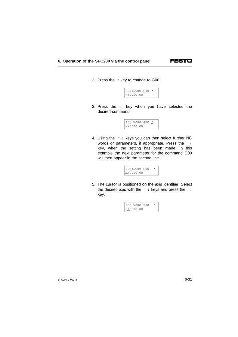
2. Press the ↑ key to change to G00.
P03:N000 G00 *X+0000.00
3. Press the → key when you have selected thedesired command.
P03:N000 G00 *X+0000.00
4. Using the ↑ ↓ keys you can then select further NCwords or parameters, if appropriate. Press the →key, when the setting has been made. In thisexample the next parameter for the command G00will then appear in the second line.
P03:N000 G00 *X+0000.00
5. The cursor is positioned on the axis identifier. Selectthe desired axis with the ↑ ↓ keys and press the →key.
P03:N000 G00 *X+0000.00
6. Operation of the SPC200 via the control panel
SPC200... 9904a 6-31

6. When the cursor is positioned next to the axis codeyou can use the ↑ ↓ keys to toggle between:
– Position value (X+0000.00 or X-0000.00)
– Register value (X@00).
– Axis not relevant (X*) Significance: The positioning command has no effectwith the corresponding axis.
7. If you have made your selection, you can, if re-quired, enter the position and/or register value withthe cursor keys. To do this proceed as usual digit-by-digit:
• Set cursor to digit positions using ← and →,
• Increase or reduce the value of the digit using ↑ ↓.
P03:N000 G00 *X+0123.45
8. If you also wish to enter a position for the secondaxis in the current NC record, position the cursoragain on the axis identifier using the ← key. Thentoggle to the desired axis and enter the positionand/or cursor value for this axis using the cursorkeys, e.g.:
P03:N000 G00 *Y+0100.00
6. Operation of the SPC200 via the control panel
6-32 SPC200... 9904a
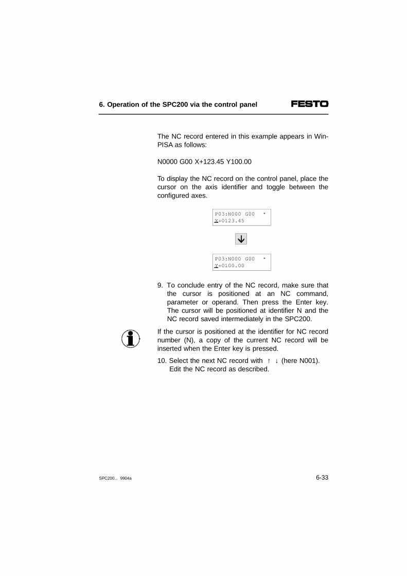
The NC record entered in this example appears in Win-PISA as follows:
N0000 G00 X+123.45 Y100.00
To display the NC record on the control panel, place thecursor on the axis identifier and toggle between theconfigured axes.
P03:N000 G00 *X+0123.45
P03:N000 G00 *Y+0100.00
9. To conclude entry of the NC record, make sure thatthe cursor is positioned at an NC command,parameter or operand. Then press the Enter key.The cursor will be positioned at identifier N and theNC record saved intermediately in the SPC200.
If the cursor is positioned at the identifier for NC recordnumber (N), a copy of the current NC record will beinserted when the Enter key is pressed.
10. Select the next NC record with ↑ ↓ (here N001). Edit the NC record as described.
6. Operation of the SPC200 via the control panel
SPC200... 9904a 6-33

Always conclude programs with NC command M30(Program end with repeat) or M02 (Subprogram end),e.g.:
P03:N005 M30
Exiting the program editor
1. First make sure that the cursor is positioned at anNC command, parameter or operand. Then pressthe Enter key to conclude the entry of the currentNC record. The cursor will then be positioned atidentifier N and the NC record saved intermediatelyin the SPC200.
P03:N005 M30
2. Press key → to position the cursor at the NC com-mand again.
P03:N005 M30
3. Now press the ESC key. The NC editor will thenbe exited.
The program will not be transferred from the intermedi-ate memory (RAM memory) to the program memory(flash memory) until the NC editor is exited. If there is apower failure before the NC editor is exited, the modifi-cations made will be lost.
6. Operation of the SPC200 via the control panel
6-34 SPC200... 9904a

6.3.2 Editing instructions
If there is a power failure before the NC editor is exited,the modifications made will be lost. When entering ex-tensive programs, exit the editor now and again in orderto save intermediately.
When programming, pay attention to correct syntax andonly use existing operands. Both lines of the display areused to display an NC record. Please note that in pro-gramming multi-axis systems, for reasons of space,only the parameter for the currently selected axis is dis-played.
In moving the cursor, the lines are to be considered asone line of 32 characters. The individual NC wordsand/or parameters are selected one after the other withthe ← and → keys. The cursor moves to the left orright correspondingly.
If the NC program already contains several lines, NCrecords can be inserted and deleted and the programcan be scrolled. For this, the cursor must be in NC rec-ord number field (e.g. N001). You can then:
Inserting,deleting
lines
– scroll through the program using the ↑ ↓ keys
– insert a copy of the current NC record by pressingthe Enter key.
– delete the current NC record by pressing the ESCkey. The deletion process can be acknowledged withEnter or recalled with ESC.
6. Operation of the SPC200 via the control panel
SPC200... 9904a 6-35

The characters and/or NC words to be modified areselected with the ← and → keys. The charactersand/or NC words are changed with the ↑ ↓ keys.
Editlines
• If the cursor is located on an NC word, an NC wordwill be selected using ↑ ↓.
• If the cursor is on a digit, the value of the digit will beraised or lowered using ↑ ↓.
• If the cursor is on the axis identifier, one of the avail-able axes will be selected with ↑ ↓.
• In the case of positioning commands, one of the fol-lowing signs to the immediate right of the axisidentifier can be selected:
Sign Meaning
+ positive position value (z.B. X+0100.00)
- negative position value (z.B. X-0100.00)
@ number of the position register (e.g. X@10)
* axis not relevant (e.g. Y*; Y-axis not relevant)
If the * sign is selected, the command programmed inthe current line is not relevant for the current axis, e.g.:
P03:N001 G00 G90 Y*
In order to conclude the entry of an NC record or pro-gram, the cursor must be positioned at an NC com-mand, parameter or operand. The NC record is con-cluded with the Enter key. Program entry is concludedwith the ESC key.
Concludingentry
6. Operation of the SPC200 via the control panel
6-36 SPC200... 9904a
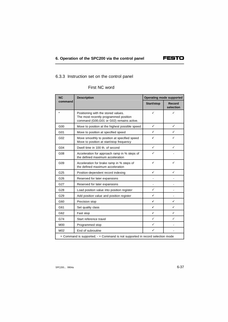
6.3.3 Instruction set on the control panel
First NC word
NC command
Description Operating mode supported
Start/stop Recordselection
* Positioning with the stored values.The most recently programmed positioncommand (G00,G01 or G02) remains active.
ä ä
G00 Move to position at the highest possible speed ä ä
G01 Move to position at specified speed ä ä
G02 Move smoothly to position at specified speedMove to position at start/stop frequency
ä ä
G04 Dwell time in 100 th. of second ä ä
G08 Acceleration for approach ramp in % steps ofthe defined maximum acceleration
ä -
G09 Acceleration for brake ramp in % steps ofthe defined maximum acceleration
ä ä
G25 Position-dependent record indexing ä ä
G26 Reserved for later expansions - -
G27 Reserved for later expansions - -
G28 Load position value into position register ä -
G29 Add position value and position register ä -
G60 Precision stop ä ä
G61 Set quality class ä ä
G62 Fast stop ä ä
G74 Start reference travel ä ä
M00 Programmed stop ä -
M02 End of subroutine ä -
= Command is supported; - = Command is not supported in record selection mode
6. Operation of the SPC200 via the control panel
SPC200... 9904a 6-37
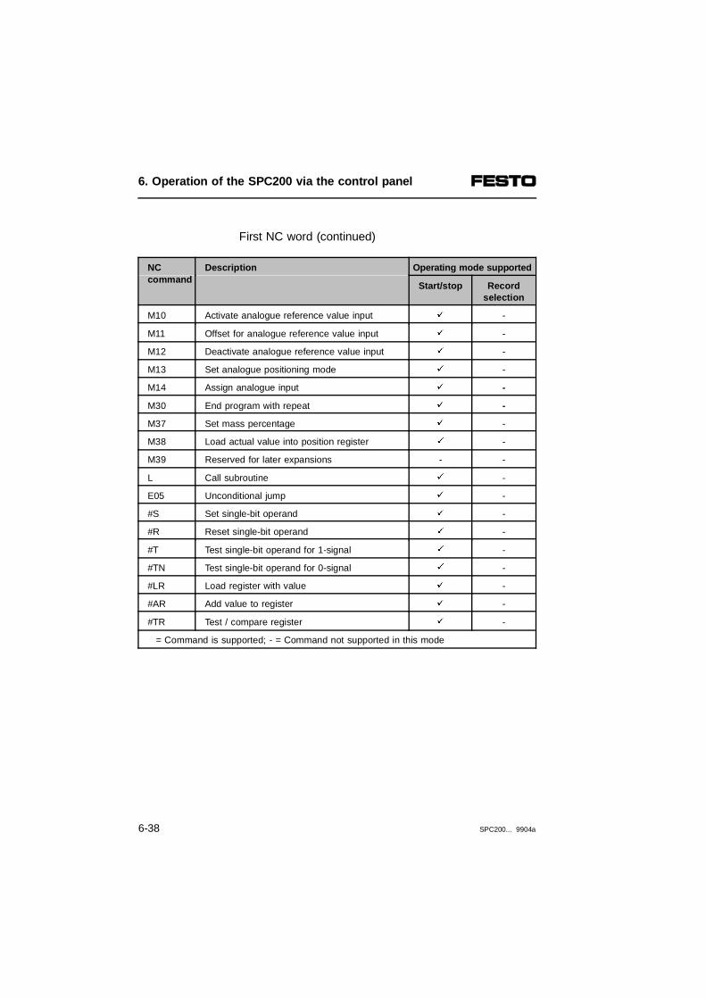
First NC word (continued)
NC command
Description Operating mode supported
Start/stop Recordselection
M10 Activate analogue reference value input ä -
M11 Offset for analogue reference value input ä -
M12 Deactivate analogue reference value input ä -
M13 Set analogue positioning mode ä -
M14 Assign analogue input ä -
M30 End program with repeat ä -
M37 Set mass percentage ä -
M38 Load actual value into position register ä -
M39 Reserved for later expansions - -
L Call subroutine ä -
E05 Unconditional jump ä -
#S Set single-bit operand ä -
#R Reset single-bit operand ä -
#T Test single-bit operand for 1-signal ä -
#TN Test single-bit operand for 0-signal ä -
#LR Load register with value ä -
#AR Add value to register ä -
#TR Test / compare register ä -
= Command is supported; - = Command not supported in this mode
6. Operation of the SPC200 via the control panel
6-38 SPC200... 9904a
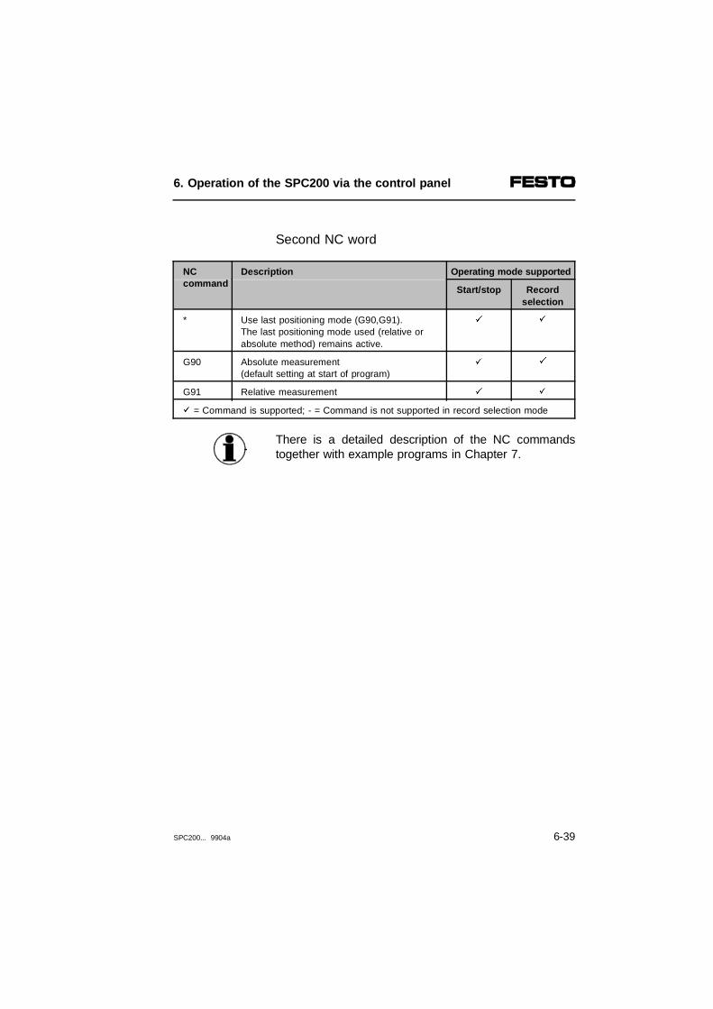
Second NC word
NC command
Description Operating mode supported
Start/stop Recordselection
* Use last positioning mode (G90,G91).The last positioning mode used (relative orabsolute method) remains active.
ä ä
G90 Absolute measurement(default setting at start of program)
ä ä
G91 Relative measurement ä ä
ä = Command is supported; - = Command is not supported in record selection mode
There is a detailed description of the NC commandstogether with example programs in Chapter 7.
6. Operation of the SPC200 via the control panel
SPC200... 9904a 6-39

6.3.4 Editing an existing program
1. In the initial display press the ← or → key re-peatedly, until the EDIT PROGRAM menu is dis-played.
SPC200 READYEDIT PROGRAM >
2. Press the Enter key to open the EDIT PROGRAMmenu. The first command (New Program) will thenbe displayed in the lower line.
EDIT PROGRAMNEW PROGRAM >
3. Select the command MODIFY PROGRAM using the← or → keys.
EDITMODIFY PROGRAM >
4. Press the Enter key to select the MODIFY PRO-GRAM command.
NEW PROGRAMPROGRAM NO: 00?
5. Insert the desired program number using the cursorkeys, e.g. Program No. 03:
NEW PROGRAMPROGRAM NO: 03?
6. Press the Enter key to edit the program.
6. Operation of the SPC200 via the control panel
6-40 SPC200... 9904a

After a program has been selected the number of theprogram will be displayed in the first 3 positions (hereP03). After this, the first NC record of the program willbe displayed, e.g.:
P03:N000 G00 *X+0100.00
The cursor stands on the current NC record number(here N000). Using the ↑ ↓ keys you can scroll throughall NC records in the program.
Please note that in programming multi-axis systems, forreasons of space, only the parameter for the currentlyselected axis is displayed.
Notes on editing are to be found in Section 6.3.2.
6. Operation of the SPC200 via the control panel
SPC200... 9904a 6-41
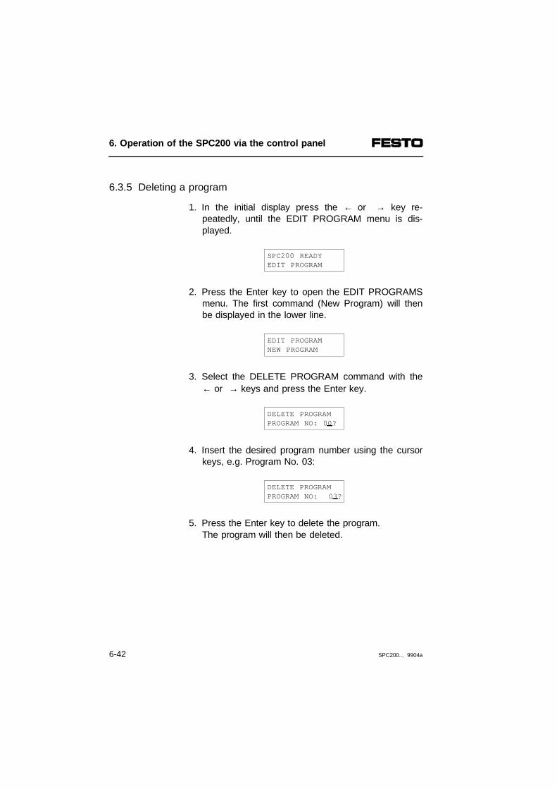
6.3.5 Deleting a program
1. In the initial display press the ← or → key re-peatedly, until the EDIT PROGRAM menu is dis-played.
SPC200 READY EDIT PROGRAM
2. Press the Enter key to open the EDIT PROGRAMSmenu. The first command (New Program) will thenbe displayed in the lower line.
EDIT PROGRAM NEW PROGRAM
3. Select the DELETE PROGRAM command with the← or → keys and press the Enter key.
DELETE PROGRAM PROGRAM NO: 00?
4. Insert the desired program number using the cursorkeys, e.g. Program No. 03:
DELETE PROGRAM PROGRAM NO: 03?
5. Press the Enter key to delete the program.The program will then be deleted.
6. Operation of the SPC200 via the control panel
6-42 SPC200... 9904a

6.4 Editing the position register
In programming, as an alternative to direct input of po-sition values (e.g. X100), you can also specify positionsby position register. Then you only need to specify thedesired number of the position register (e.g. X@01) inthe program.
With programming in WinPISA, the position registersare pre-assigned with the values of the position list (seeWinPISA manual).
The desired position values are filled into the positionregister using the following commands in the EDITPROGRAM menu.
EDIT PROGRAM menu (for editing programs)
EDIT PROGRAMMODIFY POSREG. >
Modify the position register(Edit position register)
EDIT PROGRAMTEACH IN >
Teach mode(Teach position register)
Modify position register
1. In the initial display press the ← or → key re-peatedly, until the EDIT PROGRAM menu is dis-played.
2. Press the Enter key to open the EDIT PROGRAMmenu. The first command (New Program) will thenbe displayed in the lower line.
6. Operation of the SPC200 via the control panel
SPC200... 9904a 6-43

3. Select the MODIFY POSRG command with the← or → keys and press the Enter key.
MODIFY POSREG.X:@00
4. Using the cursor keys, enter the desired axis codeand the register number, e.g. X:@03, and press theEnter key. The current value of the register will thenbe shown.
MODIFY POSREG.X:@03: +0123.00
The value -9999.99 is reserved as code for unused po-sition register.
5. You can modify the value with the cursor keys.Press the Enter key to save the change.
6. If you wish to alter another position register, pressthe ESC key and repeat Items 4 and 5.
6. Operation of the SPC200 via the control panel
6-44 SPC200... 9904a

Teaching positions
WARNINGIn this function, one or more system axes will be setin motion. Take care that no one can reach into thepath of the moving object while compressed air isapplied.
The following requirements must be fulfilled for theteach mode:
– the positioning system must be set up completely,wired and supplied with voltage and compressed air;
– the axis and application parameters must be set cor-rectly;
– the inputs ENABLE (I0.9) and STOP (I0.7) must besupplied with 24 V.
1. Press key ← or → in the initial display repeatedlyuntil the EDIT PROGRAM MENU is shown.
2. Press the ENTER key to open the EDIT PROGRAMMENU. The first command (NEW PROGRAM) willthen be shown in the bottom line.
3. Select the command TEACH IN with the keys ←and → and press the Enter key.
TEACH INX:@00 CONT
6. Operation of the SPC200 via the control panel
SPC200... 9904a 6-45
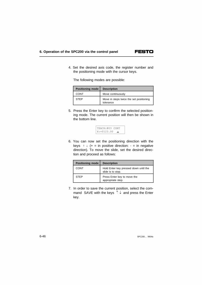
4. Set the desired axis code, the register number andthe positioning mode with the cursor keys.
The following modes are possible:
Positioning mode Description
CONT Move continuously
STEP Move in steps twice the set positioningtolerance
5. Press the Enter key to confirm the selected position-ing mode. The current position will then be shown inthe bottom line.
TEACH:@03 CONTX:+0123.00 +
6. You can now set the positioning direction with thekeys ↑ ↓ (+ = in positive direction: - = in negativedirection). To move the slide, set the desired direc-tion and proceed as follows:
Positioning mode Description
CONT Hold Enter key pressed down until theslide is to stop.
STEP Press Enter key to move theappropriate step.
7. In order to save the current position, select the com-mand SAVE with the keys and press the Enterkey.
6. Operation of the SPC200 via the control panel
6-46 SPC200... 9904a

6.5 Controlling the program run
WARNINGTake care that no one can reach into the path of themoving object and that no objects lie in this path.
In order to be able to control program runs with thecontrol panel, the following requirements must be met:
Require-ments
– the positioning system is fully installed, wired up andsupplied with voltage and compressed air
– the parameters in the menus AXIS PARAM,APPLIC.PARAM and CONFIG. SYSTEM are correct-ly set
– 24 V is available at the ENABLE (I0.9) and STOP(I0.7) inputs
– there is at least one program in the memory.
Programs can be started, stopped and reset with thefollowing commands in the SYSTEM CONTROL me-mory.
6. Operation of the SPC200 via the control panel
SPC200... 9904a 6-47

SYSTEM CONTROL menu
SYSTEM CONTROLSTART SYSTEM ?
Start system(only supported in start/stop mode)The programs created are started or continued with this command. Requirement:- 1-signal at STOP input - 1-signal at ENABLE inputWhen the system is started, the display will show the command STOP SYSTEM, so that an unintentional start canbe cancelled immediately.
SYSTEM CONTROLSTOP SYSTEM ?
Stop systemThe program and the axes are both stopped with this command. The current position becomes the nominal position(closed-loop controlled stop).
SYSTEM CONTROLRESET SYSTEM ?
Reset system The SPC200 is reset to the status it was in after it wasswitched on. A program reset and hardware recognition is carried out here and the axis interface string is reinitialized.This procedure can take a certain amount of time, dependingon the system configuration used.
SYSTEM CONTROLRESET PROGRAMS ?
Reset programsHere the: - NC record pointer is reset to 0- the pre-settings G90 and G02 (speed, acceleration and mass
load factor 100%) as well as the positioning quality class setin the application parameters become valid
- the analogue channel will be switched off (M12)- all freely programmable outputs and the SYNC outputs will
be reset- the set starting programs are made ready- any errors will be acknowledged.
SYSTEM CONTROLRESET ERROR ?
Reset errorThe error code is reset to 0 with this command.
SYSTEM CONTROLRESET DATA ?
Reset all data to the status as at delivery.With this command, all data will be reset to the status as atdelivery. All user data will then be lost.
6. Operation of the SPC200 via the control panel
6-48 SPC200... 9904a
6.6 Display of operands and system states
For program control, it is possible to have a permanentdisplay of the operands and system states. The com-mands for this are in the Display menu. The followingoperands and system states can be displayed, provid-ing the appropriate modules are fitted.
DISPLAY menu
TASK STATETA:P00 N000 S00
Task stateTn = Task (A or B) A...BPn = Current program number 0...99Nn = NC record number 0...999Snm = Program/record status 00...11*)n = Record status, m = Program status*) 0 = inactive; 1 active
REFERENCE POS.X:+0000.00 mm
Reference position X, Y, Z, U = axis identifier
CURRENT POS.X:+0000.00 mm
Current positionX, Y; Z, U = axis identifier
POS. DIFFERENCEX:+0000.00 mm
Position differenceX, Y, Z, U = axis identifier
DIGITAL INPUTI0.00:0
Status display for digital inputsI = Input I0.0...I3.15
FIELDBUS INPUTI10.00:0
Status display for field bus inputsI = Input I10.0...I13.15
DIGITAL OUTPUTQ0.00:0
Status display for digital outputsQ = Output I0.0...I3.15
FIELDBUS OUTPUTQ10.00:0
Status display for field bus outputsQ = Output I10.0...I13.15
6. Operation of the SPC200 via the control panel
SPC200... 9904a 6-49

DISPLAY menu
MEMORY FLAGF00:0
Status display for memory flagF = Flag F00...F63
REGISTERR00:+0000
Status display for registerR = Register R00...R99
ERRORNo.00000000
Error number(see section 8.2)
STEP MOTORINPUTY: LIM+ = 1
Status display for sensors on theelectric axis. If the cursor is positioned at LIM+, youcan switch between:- LIM + (positive limit switch)- LIM - (negative limit switch)- REF (reference switch)- SRDY (ready signal of the power controller)The status of each input is shown by"0" or "1". If a stepping motor indexermodule is not installed, the message"NO STEP MOTOR" will appear.
When checking the sensors, note the different designsof sensors:
– LIM +, LIM -limit switch: normally closed contact
– REFreference switch: normally open contact.
6. Operation of the SPC200 via the control panel
6-50 SPC200... 9904a
6.7 Setting the closed loop control factors
The controller parameters are calculated by theSPC200 from various basic factors. The controllerfactors are standardized to 1.0. By means of these fac-tors you can manually influence the calculated control-ler parameters.
MenuCONTROL.
PARAM
A detailed description of the controller parameters aswell as instructions on optimizing the positioning behav-iour can be found in Appendix A.
Control factors for pneumatic axes:
CONTROL. PARAM. menu (Controller parameters)
Pneumatic axis
GAIN FACTORX:+0001.00
Gain factor 0.1 ... 10.0With the gain factor you can influence the sensitivity with whichthe positioning controller reacts to the modifications to the"measured variables" (position, speed, acceleration)
DAMPING FACTORX:+0001.00
Damping factor 0.1 ... 10.0Damping is a measure of the transition behaviour of the systemfrom the actual to the nominal status, especially with fastmodifications of reference values. The system should normallyguarantee low-swing behaviour with reference value specificationand no-swing movement to the destination position.
6. Operation of the SPC200 via the control panel
SPC200... 9904a 6-51

CONTROL. PARAM. menu (Controller parameters)
FILTER FACTORX:+0001.00
Signal filter factor 0.1 ... 10.0Speed and acceleration are derived from the positioning signaland filtered to improve the signal quality. If bad signal qualityexists in practice, e.g. due to electrical interference, the filteringof the signal can be influenced by the signal filter factor. If the filtering is too strong, it may destabilize the positioning.
POS. TIMEOUTX:01.00
Positioning timeout 0.0 ... 99.99 sThis monitors to see whether the positioning procedures are carried out quickly enough. The SPC200 issues an MC error if:- the drive does not start to move within the specified positioning
timeout entered after receiving a positioning command;- the drive exceeds the maximum permitted positioning time
(sum of the internally calculated positioning time and the positioning timeout).
If there is an NC error, the drive will be stopped. The current position becomes the reference position. The error can be quittedwith a new positioning command. Select the positioning timeout so that the positioning movementscan definitely be concluded within the selected time (e.g. 0.5 to1.0 seconds). You can switch off the monitoring of the positioningtime with the value 0.0.
6. Operation of the SPC200 via the control panel
6-52 SPC200... 9904a

6.8 Test and diagnostic functions of the control panel
A ready-to-operate system is required for some of thecommands in this menu. The following conditions mustbe fulfilled:
• the positioning system must be completely set up,wired and supplied with voltage and compressed air
• the axis and application parameters must be set cor-rectly
• The inputs ENABLE and STOP must supply a1-signal.
– After opening the menu, you can test either the:system functions (SYSTEM) or
– the axis functions (AXIS)
6. Operation of the SPC200 via the control panel
SPC200... 9904a 6-53

TEST/DIAG. menu (test and diagnostics)
Submenu SYSTEM
SINGLE STEPP00
Program test in single step P00 ... P99(only supported in start/stop mode)With this function you can test an existing program in single stepmode.Proceed as follows:1. Set the program number.2. Press the Enter key to confirm the selection.3. Press the Enter key to start the NC record.4. Repeat point 3 to start the next NC record.
INPUT TESTI0.00:0
Test inputs1)
I = input I0.00 ... I3.15With this command you can check the functioning of the inputs ofthe system. The input signal entered suppresses the actualsignal present and is taken into account for the sequence control(e.g. start/stop) as well as for the program run. The actual inputsignal present is then finally valid again.
FB INPUT TESTI10.00:0
Test field bus inputs 1)
I = input I10.00...I13.15
OUTPUT TESTQ0.00:0
Test outputs1)
Q = output Q0.00...Q3.15The READY output (Q0.7) and the ACK outputs used by thesystem (Q0.5 and Q0.6) are continually updated by the operatingsystem and cannot, therefore, be influenced.
FB OUTPUT TESTQ10.00:0
Test field bus outputs 1)
Q = output QI10.00...Q13.15
FLAG TESTF00:0
Test flags1)
F = flag F00...F63
REGISTER TESTR00:0
Test registers1)
R = register R00...R99
1) With this command the status of the appropriate operand can be modified.
6. Operation of the SPC200 via the control panel
6-54 SPC200... 9904a

TEST/DIAG. menu (test and diagnostics)
Submenu AXIS: pneumatic axis
JOG AXISX: CONT
Jog axisCONT : move continuouslySTEP : move step-by-step twice the
set positioning toleranceProceed as follows:1. Select the desired axis (X or Y)2. Select the positioning mode (CONT, STEP).3. Press the Enter key to confirm the selection.4. Select the positioning direction (+ or -).5. With positioning mode STEP:
- Press the Enter key to move one step.With positioning mode CONT:- Press and hold down the Enter key until positioning is complete.
MOVEMENT TESTX:05.00 V
Movement test 00.00 ... 10.00 VWith this command you can check whether the proportional directional control valve is correctly connected to the axis.Instructions on this procedure can be found in section 4.3.
IDENTIFICATIONX:STATIC
IdentificationSTATIC :static identificationDYNAMIC1 :dynamic identification with work loadDYNAMIC2 :dynamic identification without work load(the work load set in the application parameters is valid)Instructions on this procedure can be found in section 4.3.
6. Operation of the SPC200 via the control panel
SPC200... 9904a 6-55

TEST/DIAG. menu (test and diagnostics)
Submenu AXIS: electric axis
JOG AXISX: +0000.00 +
Move axis 1)
EXIT FROM LIMITX:+0000.00 ?
Emergency travel 1)
REFER. TRAVELX:+0000.00 ?
Reference travel 1)
1) Explanations and instructions on how to carry out these activities can be found in the manual for the stepping motor indexer module type P.BE-SPC200-SMX-1-... .
6. Operation of the SPC200 via the control panel
6-56 SPC200... 9904a

Chapter 7
Description of the commands
7. Description of the commands
SPC200... 9904a 7-1

Contents
7. Description of the commands
7.1 General notes on programming..................................................... 7-47.1.1 Coordinated and autonomous mode ............................................. 7-57.2 Notes on programming via the control panel ................................ 7-87.2.1 Explanation of the NC commands on the control panel ............. 7-13
7. Description of the commands
7-2 SPC200... 9904a
This chapter contains basic information on programm-ing the SPC200 by means of the control panel. Boththe coordinated mode and the autonomous mode ofoperation are explained, as well as all the NC com-mands.
Contents ofthis chapter
Before programming with the control panel, you shouldbe familiar with the way in which the control panel func-tions. Please refer to chapter 6 for a description of howyou can create and edit NC programs with the controlpanel.
Furtherinformation
WinPISA offers user-friendly editing functions. Informa-tion on this can be found in the WinPISA manual.
7. Description of the commands
SPC200... 9904a 7-3

7.1 General notes on programming
The following must be taken into account in preparingNC programs:
– the operating mode, in which the SPC200 is used.All NC commands are supported in start/stop mode.In record select mode only motion commands (G00,G01, G02 and G74) motion conditions (G08, G09,G90 and G91) and commands for setting the qualityclass (G60, G61, G62) are supported.
– the number of starting programs.If a single axis system or a multi-axis system is con-trolled with one SPC200, only one starting program isusually defined. If two independent work stations arecontrolled, a separate starting program must bedefined for each work station (autonomous operationof two work stations).
Parallel program processing
The SPC200 has a parallel program processing capabi-lity to provide a cost-effective way of implementing twowork stations. For this purpose, two programs, whichcan be run in parallel as Task A and Task B, must bedefined as starting programs.
Each task, and thus each starting program andsubroutine may only contain commands for the relevantassigned work station.
7. Description of the commands
7-4 SPC200... 9904a

7.1.1 Coordinated and autonomous mode
Parallel program processing is not usually used in thecoordinated control of two axes. Only one program isdefined as the starting program. The motion commandsfor all the axes are programmed in this program.
Coordinatedmode
If a motion command relates to all the axes, it is onlyterminated when all the axes have reached the targetposition. The movement of all the axes is thussynchronised. A second starting program can be usedfor supervisory functions.
123
Task AStarting program for task ASubroutines
456
Motion command for the X axisMotion command for the Y axisWorkstation A (two coordinated axes)
Fig. 7/1: Coordinated mode for two axes (example of two-axis system)
6N00010 G62 X YN00020 G00 X100 Y150N00030 #TNI0.0 30N00040 G01 X100 FX10N00050 G00 X300 Y100N00060 G00 X500 Y200N00070 G01 Y400 FY20...
4 5
1
2
3
X
Y
7. Description of the commands
SPC200... 9904a 7-5

In autonomous mode two separate work stations arecontrolled with one SPC200. Two different programswhich operate independently of one another (parallel)are defined as starting programs for this special case.
Autonomousmode
The two parallel running programs have the outputREADY in common and the inputs ENABLE, STOP andSTART/RESET.
12345
Task A Starting program for task ASubroutine for task AMotion command for the X axisTask B
67890
Starting program for task BSubroutine for task BMotion command for the Y axisWorkstation A (X axis)Workstation B (Y axis)
Fig. 7/2: Autonomous operation of two work stations (example)
N00010 G62 YN00020 G00 Y150N00030 G01 Y300 FY10N00040 #TNI0.1 40N00050 G00 Y100N00060 G04 500
N00010 G62 XN00020 G00 X100N00030 #TNI0.0 30N00040 G01 X100 FX10N00050 G00 X300N00060 G00 X500N00070 G00 X500...
X
Y
84
51
62
7
9
0
3
7. Description of the commands
7-6 SPC200... 9904a

In autonomous mode the programs for the two workstations run independently. Each work station can becontrolled independently of the other via the freely pro-grammable I/Os (start/stop mode) or the command I/Os(record select mode).
Note in using parallel program processing in autono-mous mode:
– Starting programs may not be called up as subrou-tines.
– Subroutines which contain motion commands mayonly be used by one starting program.
– Each task and all programs used may each only contain motion commands for the relevant workstation, e.g.:Task A only commands for the X axisTask B only commands for the Y axis
7. Description of the commands
SPC200... 9904a 7-7

7.2 Notes on programming via the control panel
The SPC200 can employ up to 100 motion programswith an overall maximum of 2000 NC records. Eachprogram can be called as a subroutine. 4 nested sub-routine calls are possible for this purpose.
One program can consist of up to 1000 NC records(000...999). Each NC record is given a record number.Record numbers begin with the letter N (for NC recordnumber).
When programming with the control panel the recordsare numbered in strict numerical order, beginning withN000. The NC programs are based on DIN 66025. Thefollowing symbols are employed in programming:
Symbol Description
N Identifier for record numbers (N000...N999)
G Positioning conditions
M Auxiliary functions
E Jump functions
L Call subroutine
X, Y, Z, U Axis identifiers: X axis, Y axis, etc.
F Speed
@ - Identifier for position register- Identifier for symbolic position*)
# Single and multiple-bit operations
; Start of comment, valid to end of line*)
*) only in programming with WinPISA
7. Description of the commands
7-8 SPC200... 9904a
Addressing
The assignment of the I/O address range depends onthe configuration of the SPC200. If a field bus moduleis fitted, the address range 0.0 ... 0.9 will remain unas-signed. The assignment of the I/O addresses for con-figurations with and without the field bus module areshown in the following table.
Configuration withoutfield bus module
Configuration withfield bus module
Maximum address range
First I/O module - 1) I0.0 ... I0.9 1) Q0.0 ... Q0.7 1)
I/O module on first axis interface string I1.0 ... I1.15 Q1.0 ... Q1.15
Second I/O module First I/O module I2.0 ... I2.9 Q2.0 ... Q2.7
I/O module on first axis interface string I3.0 ... I3.15 Q3.0 ... Q3.15
Third I/O module Second I/O module I4.0 ... I4.9 Q4.0 ... Q4.7
Fourth I/O module Third I/O module I5.0 ... I5.9 Q5.0 ... Q5.7
- 2) Field bus module I10.0 ... I13.15 2) Q10.0 ... Q13.152)
1) Address range not available if a field bus module is fitted2) Address range not available if a field bus module is not fitted
Control inputs and outputs are reserved for pre-assigned functions (see chapter 5).
7. Description of the commands
SPC200... 9904a 7-9

Operand Description Address range Value range
F Flag 1) F0 .. F63 0/1
R Register 1) R0 .. R99 -32767...+32767
Positionregister
Description Number Value range
@ 100 position register per axis 1) @00...@99 -9999.98...+9999.992)
1) These operands are saved in the event of a power failure (remanent)2) Value -9999.99 is reserved as code for unused position registers
Explanations of syntax
To explain the syntax the following symbols are used inthe summary tables:
Symbol Description
n Placeholder for numerical values
<Operand> Placeholder for operands (e.g. F0.0)
[ ] Parameters given in square brackets can besupplied as an alternative or in addition1)
| Parameters separated by a vertical strokecan be supplied as alternatives
1) To facilitate reading, axis identifiers are shown in a simplifiedform [Y., Z.., U..]. Additional parameters have been omitted intentionally.
7. Description of the commands
7-10 SPC200... 9904a
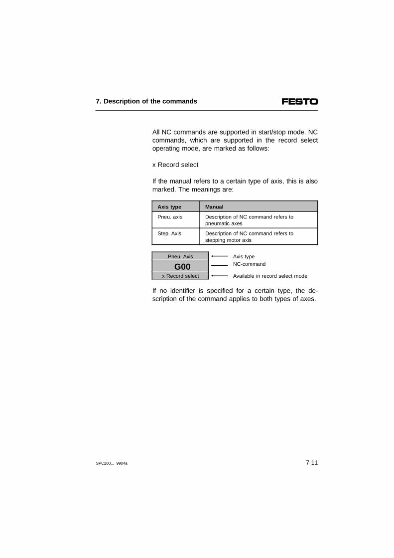
All NC commands are supported in start/stop mode. NCcommands, which are supported in the record selectoperating mode, are marked as follows:
x Record select
If the manual refers to a certain type of axis, this is alsomarked. The meanings are:
Axis type Manual
Pneu. axis Description of NC command refers topneumatic axes
Step. Axis Description of NC command refers tostepping motor axis
Pneu. Axis Axis type
G00 NC-command
x Record select Available in record select mode
If no identifier is specified for a certain type, the de-scription of the command applies to both types of axes.
7. Description of the commands
SPC200... 9904a 7-11
The following are preset for positioning:Presetting
– Positioning command G02with pneumatic axes: move smoothly to position atdefined speed (G02);with stepping motor axes: move to position atstart/stop frequency
– Absolute positioning (G90)
– With pneumatic axes:the positioning quality class (1...6) set in the applica-tion parameters is valid; speed factor, accelerationfactor and mass load factors are 100 %
The commands are explained in the sequence in which they appear when selected on the control panel.
7. Description of the commands
7-12 SPC200... 9904a

7.2.1 Explanation of the NC commands on the control panel
NC commands for the SPC200
Pneu. axis Move to position at the highest possiblespeed (point to point)G00
x Record selection
Structure Nn G00 [G90|G91] Xn|X@n [X..,Y..,Z..,U..]
Parameter Xn X@n
Position in mm; n = ± 9999.99Position register; n = 0...99
Action The pneumatic axis moves at the highest possible speed from thepresent position to the reference position (absolute or relative, seeunder G90/G91).The automatically generated reference values for speed and acceleration are limited to the maximum values determined during identification, in order to avoid overswing as a result ofstress (see following diagram).
Example N000 G00 G91 X100N001 G00 G90 X@2
N003 G00 X100 Y-100N004 G00 X@5 Y@1
;Move 100 mm in positive direction;Move to position from position ;register 2 of the X axis;Move to X100 and Y-100;Move to position from position reg-;ister 5 (X) and position register 1 (Y)
Remarks The following is set when the system is started:- Absolute positioning (G90)The command G00 will be stored. It will remain active untilcancelled by a G01 or G02 command.Example: N000 G00 X100
N001 X200N002 G01 X300
When programming with WinPISA positions can also be specifiedsymbolically. For this purpose the position values and the positionnames are entered in the position list.Example: N006 G00 x@ABHOL_POS
N007 x@ABLAGE_POS
7. Description of the commands
SPC200... 9904a 7-13

With the command G00, reference value curves arespecified by the SPC200 for path, speed and accelera-tion. These values enable a reproducible fast and no-overswing approach of the reference position.
The defined maximum speed and acceleration is onlyeffective with the positioning commands G01 and G02.
1234
Reference speedIdentified maximum speedConfigured maximum speed (G01/G02)Reference position
567
Reference acceleration Identified maximum accelerationConfigured maximum acceleration(G01/G02)
Fig. 7/3: Reference values with command G00 (pneumatic axis)
1 4
7
6
5
2
3
s [m]v [m/s]
t [s]
a [m/s2]t [s]t [s]
7. Description of the commands
7-14 SPC200... 9904a

Step. axis Move to position at highest possible speed(point to point)G00
x Record selection
Structure Nn G00 (G90|G91) Xn|X
Parameter Xn X@n
Position in mm; n = ± 9999.99Position register; n = 0...99
Action The stepping motor axis moves at the maximum speed andmaximum acceleration specified in the application parametersfrom the current position to the defined position (absolute orrelative, see under G90/G91).
Example As with pneumatic axes (see under G00 for pneumatic axis)
Remarks As with pneumatic axes (see under G00 for pneumatic axis)
7. Description of the commands
SPC200... 9904a 7-15

With the stepping motor axis, the setpoint speed valueincreases at first in ramp form with command G00, untilthe maximum speed specified in the application par-ameters is reached. Before the setpoint position isreached, the setpoint speed value falls again in rampform. The steepness of the approach and brakingramps is preset by the maximum acceleration defined inthe application parameters.
123
Setpoint speed valueConfigured maximum speedSetpoint position value
45
Setpoint acceleration valueConfigured maximum acceleration
Fig. 7/4: Setpoint specifications with command G00 (stepping motor axis)
1 3
4
2
s [m]v [m/s]
t [s]
a [m/s2]t [s]t [s]
5
7. Description of the commands
7-16 SPC200... 9904a

G01 Move to position at specified speed x Record selection
Structure Nn G01 [G90|G91] Xn|X@n FXn [Y..,Z..,U..]
Parameter Xn X@nFXn
Position in mm; n = ± 9999.99Position register; n = 0...99Speed of movement in % of thespecified maximum speed;n = 0...990 = 100 %, 1 = 1 % ...99 = 99 %
Action The axis moves at the specified speed and acceleration from thepresent position to the specified position (absolute or relative),subject to the speed being attainable by the system (see followingdiagram). With pneumatic axes: The reference values for speed andacceleration will be limited automatically to the maximum valuesdetermined during dynamic identification in order to avoidoverswing as a result of stress.
Example N000 G01 X100 FX10
N001 G01 X@2 FX30
;Move to position 100 at 10 % of the;specified maximum speed;Move to position from register 2 ;at 30 % of the specified maximum ;speed
Remarks To determine the set positioning time resulting from the referencevalues see appendix A.The following are set when the system is started:- Positioning mode = Absolute positioning (G90);- Approach ramp = 100 % of the maximum acceleration (G08);- Brake ramp = 100 % of the maximum acceleration (G09).The command G01 will be stored. It will remain active untilcancelled by a G00 or G02 command.Example: N003 G01 X100 FX10
N004 X200N005 G00 X300
When programming with WinPISA positions can also be allocatedsymbolically. For this purpose the position values and the positionnames are entered in the position list.Example:N005 G01 x@ABHOL_POS FX20 y@ABHOL_POS FY30N006 x@ABLAGE_POS
7. Description of the commands
SPC200... 9904a 7-17

With the G01 command the reference speed increasesramp-like initially, until the maximum speed of move-ment programmed with FX or FY is reached. Beforereaching the intended position the reference speeddrops again ramp-like. The steepness of the approachramp and brake ramp is preset by the maximum ac-celeration defined by the system data. The slope of theramps can be set by program independently of eachother using the G08 and G09 commands.
1234
Reference speedConfigured maximum speedProgrammed speed Reference position
5678
Reference acceleration Configured maximum accelerationProgrammed acceleration for approach ramp (G08)Programmed acceleration for brake ramp (G09)
Fig. 7/5: Reference values with command G01
1 4
6
5
2
3
s [m]v [m/s]
t [s]
a [m/s2]t [s]t [s]
8
7
7. Description of the commands
7-18 SPC200... 9904a

Pneu. axis Move smoothly to position at specified speedG02
x Record selection
Structure Nn G02 [G90|G91] Xn|X@n FXn [Y..,Z..,U..]
Parameter Xn X@nFXn
Position in mm; n = ± 9999.99Position register; n = 0...99Positioning speed in % of thespecified maximum speed;n = 0...990 = 100 %, 1 = 1 % ... 99 = 99 %
Action The pneumatic axis moves smoothly at the specified speed andacceleration from the present position to the specified position(absolute or relative), provided the system can reach this speed.The programmed reference acceleration values are mediumvalues (see following diagram). The resulting reference values arelimited automatically to the maximum values determined duringdynamic identification, in order to avoid overswing as a result ofstress.
Example N010 G02 X90 FX0
N011 G02 X@2 FX30
;Move to position X90 at 100 % of the;specified maximum speed;Move to position from register 2;at 30 % of the specified maximum;speed
Remarks To determine the set positioning time resulting from the referencevalues see appendix A.This command reduces jolting movements of the slide duringstarting and braking. The following are set when the system is started:- Absolute positioning (G90);- Approach ramp = 100 % of the maximum acceleration (G08);- Brake ramp = 100 % of the maximum acceleration (G09).The command G02 will be stored. It will remain active untilcancelled by a G00 or G01 command.When programming with WinPISA positions can also be allocatedsymbolically. For this purpose the position values and the positionnames are entered in the position list.Example:N10 G02 x@ABHOL_POS FX20 x@ABHOL_POS FY30
7. Description of the commands
SPC200... 9904a 7-19

In the case of the G02 command the acceleration refer-ence value has a sine2-shaped curve. The effect of thisis to reduce sudden changes in the positioning signaland consequently any jolting motion of the slide onapproach ramp and brake ramp. As with the G01 com-mand, the G02 command increases the referencespeed ramp-like initially, until the given speed of move-ment is attained. The programmed reference accelera-tion values of the approach ramp and brake ramp aremedium values. The peak values lie higher by the fac-tor 2, in order to reach the same positioning times aswith G01.
1234
Reference speedConfigured maximum speedProgrammed speed Reference position
5678
Reference acceleration Effective reference acceleration valueProgrammed acceleration for approch ramp (G08)Programmed acceleration for brake ramp (G09)
Fig. 7/6: Reference values with command G02
1 4
6
5
2
3
s [m]v [m/s]
t [s]
a [m/s2]t [s]t [s]
8
7
7. Description of the commands
7-20 SPC200... 9904a
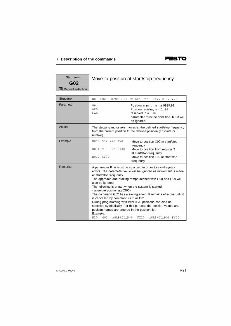
Step. axis Move to position at start/stop frequencyG02
x Record selection
Structure Nn G02 [G90|G91] Xn|X@n FXn [Y..,Z..,U..]
Parameter Xn X@nFXn
Position in mm; n = ± 9999.99Position register; n = 0...99reserved; n = .. 99parameter must be specified, but it willbe ignored
Action The stepping motor axis moves at the defined start/stop frequencyfrom the current position to the defined position (absolute orrelative).
Example N010 G02 X90 FX0
N011 G02 X@2 FX30
N012 X100
;Move to position X90 at start/stop ;frequency;Move to position from register 2;at start/stop frequency;Move to position 100 at start/stop ;frequency
Remarks A parameter F...n must be specified in order to avoid syntax errors. The parameter value will be ignored as movement is madeat start/stop frequency. The approach and braking ramps defined with G08 and G09 willalso be ignored.The following is preset when the system is started:- absolute positioning (G90)The command G02 has a saving effect. It remains effective until itis cancelled by command G00 or G01.During programming with WinPISA, positions can also bespecified symbolically. For this purpose the position values andposition names are entered in the position list.Example:N10 G02 x@ABHOL_POS FX20 x@ABHOL_POS FY30
7. Description of the commands
SPC200... 9904a 7-21

G04 Dwell time
Structure Nn G04 n
Parameter n Dwell time in 10 ms; n = 1...9999
Action Switching to the next NC record does not take place until thedwell time has expired.
Example N010 G00 X100N011 G04 250N012 G00 X200
;Move to position X100;Wait 2.5 seconds;Move to position X200
G08 Acceleration for approach ramp
x Record selection
Structure Nn G08 Xn [Y..,Z..,U..]
Parameter Xn Acceleration in % steps of thedefined maximum acceleration;n = 0...99,0 = 100 %, 1 = 1 % ...99 = 99 %
Action When positioning takes place with the following commands,approach will be made at maximum with the accelerationspecified here.With pneumatic axes: G01 and G02With stepping motor axis: G01
Example N020 G08 X50 Y50N021 G01 X80 FX50N022 G08 X0
;Approach ramp = 50 %;Move to position X80;Approach ramp at maximum ;acceleration
The X axis will only be accelerated at 50 % of the definedacceleration in moving to position X80. Finally, the acceleration forthe X axis will be switched to maximum acceleration.
Remarks This command will be stored. It will remain active until a new approach ramp is defined.
7. Description of the commands
7-22 SPC200... 9904a

G09 Acceleration for brake rampx Record selection
Structure Nn G09 Xn [Y..,Z..,U..]
Parameter Xn Acceleration in % steps of thedefined maximum acceleration;n = 0...99,0 = 100 %, 1 = 1 % ...99 = 99 %
Action When positioning takes place with the following commands,braking is made at maximum with the following acceleration.With pneumatic axes: G01 and G02With stepping motor axis: G01
Example N000 G09 X50 N001 G01 X100 FX50 N002 G01 X150 FX50N003 G09 X0
;Brake ramp = 50 %;Move to position X100;Move to position X150;Brake ramp at maximum ;acceleration
Remarks This command will be stored. It will remain active until a new brake ramp is defined.
7. Description of the commands
SPC200... 9904a 7-23
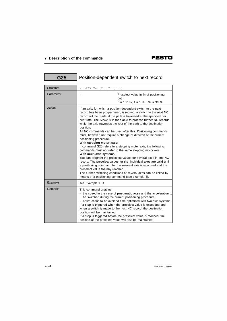
G25 Position-dependent switch to next record
Structure Nn G25 Xn [Y..,Z..,U..]
Parameter n Preselect value in % of positioningpath;0 = 100 %, 1 = 1 % ...99 = 99 %
Action If an axis, for which a position-dependent switch to the nextrecord has been programmed, is moved, a switch to the next NCrecord will be made, if the path is traversed at the specified percent rate. The SPC200 is then able to process further NC records,while the axis traverses the rest of the path to the destinationposition. All NC commands can be used after this. Positioning commandsmust, however, not require a change of directon of the current positioning procedure.With stepping motor axes: If command G25 refers to a stepping motor axis, the followingcommands must not refer to the same stepping motor axis.With multi-axis systems: You can program the preselect values for several axes in one NCrecord. The preselect values for the individual axes are valid untila positioning command for the relevant axis is executed and thepreselect value thereby reached.The further switching conditions of several axes can be linked bymeans of a positioning command (see example 4).
Example see Example 1...4
Remarks This command enables:- the speed in the case of pneumatic axes and the acceleration to
be switched during the current positioning procedure.- obstructions to be avoided time-optimized with two-axis systems. If a stop is triggered when the preselect value is exceeded andwhen a switch is made to the next NC record, the destinationposition will be maintained.If a stop is triggered before the preselect value is reached, theposition of the preselect value will also be maintained.
7. Description of the commands
7-24 SPC200... 9904a

Switching over the speed/acceleration (only with pneumatic axes)
Transfer to a new setpoint speed is made with the cur-rent set values for approach acceleration and braking.Automatic limiting to realizable braking values is notundertaken.
CAUTIONUnrealistically high acceleration values can lead tohigh oscillation and therefore to damage to the axis.If you use command G25, make sure that realizableacceleration values are set in relation to the axisused and the remaining positioning path.
If the remaining positioning path is not sufficient forcoming to a stand with the set braking, a stop will betriggered automatically (error no. nnn03x06). In thiscase, move the switching conditon forwards or set asteeper braking ramp.
With G02 positioning commands, an automatic stop canalso be triggered when the conditon for further switch-ing is in the range of the braking phase. In this case,use positioning command G01 (calculation forms seeAppendix A).
7. Description of the commands
SPC200... 9904a 7-25

Modify speed; only permitted with pneumatic axesExample 1
N000 G00 X0N001 G25 X60N002 G01 X500 FX75N003 G01 X500 FX50
The SPC200 reduces the speed from 75 % to 50 % ofthe specified maximum speed after covering 60 % ofthe distance from position 0 to position 500.
12
Speed in % of the specified maximum speedPre-shutdown value of the X axis
Fig. 7/7: Example - modify speed (only permitted withpneumatic axes)
Switching to the highest possible speed (NC commandG00) whilst the system is running is not permitted.
100
50%
75%
25%
300 400200
1
2
7. Description of the commands
7-26 SPC200... 9904a

Time-optimized translationExample 2
N010 G00 X100 Y100N011 G25 X50N012 G00 X400N013 G00 Y300
After moving 50 % of the distance from position X100to position X400 the axis controller sets the processesthe next NC record.
123
Positioning path of the Y axis in mmPre-shutdown value of the X axisPositioning path of the X axis in mm
Figure 7/8: Example: Time-optimized translation
The Y-axis therefore begins to move to position Y300,although the X-axis has not yet concluded the position-ing movement.
100
200
300
100
300 400200
1
2
3
7. Description of the commands
SPC200... 9904a 7-27

Event-dependent switching to next recordExample 3
N010 G00 X0N011 G25 X1N012 G01 X500 FX60N013 #TNI0.0 13N014 G01 X500 FX10
When 1% of the positioning path from X0 to X500 hasbeen traversed, the SPC200 switches further to NCrecord N013. A pause is made in this record until theevent takes place (here 1-signal at input I0.0). Onlythen or during positioning, a switch is made to the nextpositioning task (here speed reduction).
If the event occurs after the destination position hasbeen reached, the following positioning command inthis example will have no effect, as the same destina-tion position (X500) has been programmed.
7. Description of the commands
7-28 SPC200... 9904a
Linked further switching conditionExample 4
N010 G01 X0 FX0 Y0 FY0 Z0 FZ0N011 G25 X10 Y10 Z10N012 G01 X100 FX10N013 #SQ0.0N014 G01 Y100 FY10 Z100 FZ10N015 .......
In NC record N011, the SPC200 saves preselect valuesfor the axes X, Y and Z. In the next NC record only theX-axis will be moved. When the X-axis reaches thepreselect value, output Q0.0 will be set.
In NC record N014 the axes Y and Z are moved. Aswitch is made to the next NC record when both axesreach the preselect value programmed under N011(AND linking).
If, in addition to the axis for which a preselect value hasbeen programmed, other axes are to be positioned withthe same NC record, a preselect value of 100% willapply to these axes.
N015 G01 X0 FX0 Y0 FY0N016 G25 X50N017 G01 X200 FX0 Y200 FY0N018 #SQ0.0N019 .......
Output Q0.0 will be set when the Y-axis reaches posi-tion Y200 and when the X-axis reaches the pro-grammed preselect value (here X100).
7. Description of the commands
SPC200... 9904a 7-29

G26 Reserved for later expansions
Structure
Parameter
Action
Example
Remarks
G27 Reserved for later expansions
Structure
Parameter
Action
Example
Remarks
7. Description of the commands
7-30 SPC200... 9904a
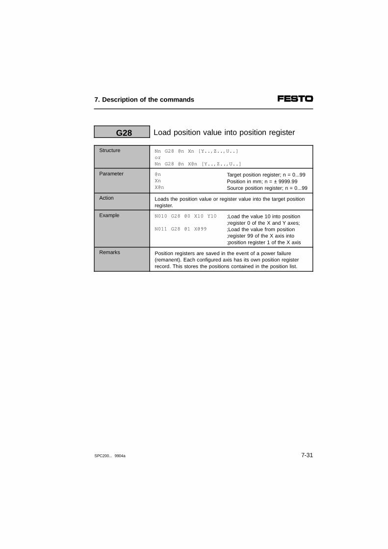
G28 Load position value into position register
Structure Nn G28 @n Xn [Y..,Z..,U..]orNn G28 @n X@n [Y..,Z..,U..]
Parameter @nXnX@n
Target position register; n = 0...99Position in mm; n = ± 9999.99Source position register; n = 0...99
Action Loads the position value or register value into the target position register.
Example N010 G28 @0 X10 Y10
N011 G28 @1 X@99
;Load the value 10 into position;register 0 of the X and Y axes;;Load the value from position ;register 99 of the X axis into ;position register 1 of the X axis
Remarks Position registers are saved in the event of a power failure(remanent). Each configured axis has its own position registerrecord. This stores the positions contained in the position list.
7. Description of the commands
SPC200... 9904a 7-31

G29 Add position value and position register
Structure Nn G29 @n Xn [Y..,Z..,U..]orNn G29 @n X@n [Y..,Z..,U..]
Parameter @nXnX@n
Target position register; n = 0...99Position in mm; n = ± 9999.99Source position register; n = 0...99
Action Forms the sum of the position value and register value or of tworegister values and stores the result in the target register.
Example (Register @X10=20) N010 G29 @10 X+10.5 ;Add position value and position
;register value of the X-axis
The reference position 10.5 and the value from position register10 of the X axis (here 20) are added. The result (30.5) is stored inposition register 10 of the X axis.
Remarks Position registers are saved in the event of a power failure(remanent). Each configured axis has its own position registerrecord. This stores the positions contained in the position list.
7. Description of the commands
7-32 SPC200... 9904a

Pneu. axis Precision stopG60
x Record selection
Structure Nn G60 X [Y, Z, U]
Parameter X Axis designation
Action Switches to precision stop (Quality class 3). The MC signal is sentif the specified axis is still in the tolerance range when themonitoring time has expired.
Example N000 G60 XN001 X100
;Activate precision stop;Move to position X100
(Example: Tolerance = 0.2 mm):During movement to position 100 mm, the MC signal is sentproviding the X-axis remains for a long period in the tolerancerange (between 99.8 mm...100.2 mm).
Remarks This command will be stored. It will remain effective until a faststop is selected with the G62 command or any other quality classwith G61.
123
Reference positioning valueTolerance rangeDuration of monitoring period per cylinder length
456
Expiration of monitoring periodMonitoring periodMC signal on precision stop
Fig. 7/9: Precision stop
0
1
0
1
1
6
2 3
45
s [m]
t [s]
7. Description of the commands
SPC200... 9904a 7-33
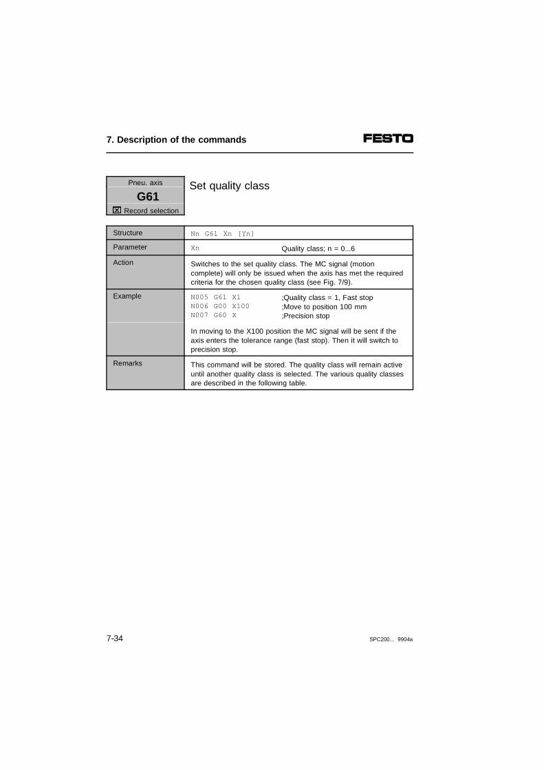
Pneu. axis Set quality classG61
x Record selection
Structure Nn G61 Xn [Yn]
Parameter Xn Quality class; n = 0...6
Action Switches to the set quality class. The MC signal (motioncomplete) will only be issued when the axis has met the requiredcriteria for the chosen quality class (see Fig. 7/9).
Example N005 G61 X1N006 G00 X100N007 G60 X
;Quality class = 1, Fast stop;Move to position 100 mm ;Precision stop
In moving to the X100 position the MC signal will be sent if theaxis enters the tolerance range (fast stop). Then it will switch toprecision stop.
Remarks This command will be stored. The quality class will remain activeuntil another quality class is selected. The various quality classesare described in the following table.
7. Description of the commands
7-34 SPC200... 9904a
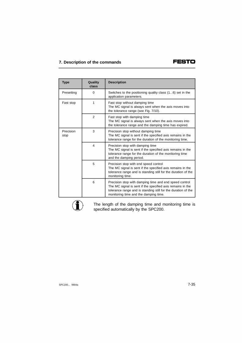
Type Qualityclass
Description
Presetting 0 Switches to the positioning quality class (1...6) set in theapplication parameters.
Fast stop 1 Fast stop without damping timeThe MC signal is always sent when the axis moves intothe tolerance range (see Fig. 7/10).
2 Fast stop with damping timeThe MC signal is always sent when the axis moves intothe tolerance range and the damping time has expired.
Precisionstop
3 Precision stop without damping timeThe MC signal is sent if the specified axis remains in thetolerance range for the duration of the monitoring time.
4 Precision stop with damping timeThe MC signal is sent if the specified axis remains in thetolerance range for the duration of the monitoring timeand the damping period.
5 Precision stop with end speed controlThe MC signal is sent if the specified axis remains in thetolerance range and is standing still for the duration of themonitoring time.
6 Precision stop with damping time and end speed controlThe MC signal is sent if the specified axis remains in thetolerance range and is standing still for the duration of themonitoring time and the damping time.
The length of the damping time and monitoring time isspecified automatically by the SPC200.
7. Description of the commands
SPC200... 9904a 7-35

Pneu. axis Fast stopG62
x Record selection
Structure Nn G62 X [Y, Z, U]
Parameter X Axis designation
Action Switches to fast stop. The MC signal (motion complete) is alwayssent when the axis moves into the tolerance range the first time(see Fig. 7/9).
Example N000 G60 XN001 G00 X200N002 G62 XN003 G00 X100N004 G00 X300
;Activate precision stop ;Move to position X200;Activate fast stop;Move to position X100;Move to position X300
In moving to the X100 position the MC signal (motion complete)will be sent if the axis enters the tolerance range. The SPC200 isimmediately ready to move to position X300.
Remarks This command will be stored. The fast stop will remain active untilanother quality class is selected.
12
Reference positioning valueTolerance range
34
Reaching the tolerance rangeMC signal in the case of fast stop
Fig. 7/10: Fast stop
01
1
2
3
4
7. Description of the commands
7-36 SPC200... 9904a

Step. axis Start reference travelG74
x Record selection
Structure Nn G74 X [Y..,Z..,U..]
Parameter X Reference travel mode; n = 0...4
Action Starts reference travel in the specified mode (see diagram below)
Example N000 G74 X0 ;transfer current position as reference;point
Remarks All positions refer indirectly to the reference point. The exactposition of the switching point of the reference switch depends onthe reference travel mode selected.
Mode Description
0 Transfers current axis position as reference point
1 Reference travel in negative direction up to reference switch(REF) with transfer as reference point
2 Reference travel in negative direction up to negative end switch(LIM-) with transfer as reference point
3 Reference travel in positive direction up to reference switch (REF)with transfer as reference point
4 Reference travel in positive direction up to positive end switch(REF) with transfer as reference point
7. Description of the commands
SPC200... 9904a 7-37
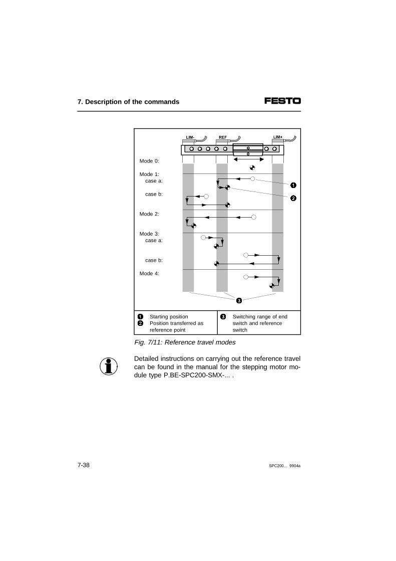
Mode 0:
Mode 1:case a:
case b:
Mode 2:
Mode 3:case a:
case b:
Mode 4:
12
Starting positionPosition transferred as reference point
3 Switching range of endswitch and referenceswitch
Fig. 7/11: Reference travel modes
Detailed instructions on carrying out the reference travelcan be found in the manual for the stepping motor mo-dule type P.BE-SPC200-SMX-... .
3
1
2
7. Description of the commands
7-38 SPC200... 9904a

G90 Absolute measurementx Record selection
Structure Nn G90 Xn|X@n [Y..,Z..,U..]
Parameter Xn X@n
Position in mm; n = ± 9999.99Position register; n = 0...99
Action Switches to absolute positioning and moves at current speed and,if relevant, with current ramp to given absolute position. Allsubsequent positions in the program will be interpreted asabsolute. The positioning mode remains valid until a newpositioning mode is set (see also under G00/G01/G02).
Example N000 G00 G90 X200
N001 X100
N002 X@5 Y@1
N003 G90 Y100N004 G91 X100
;Move at highest possible speed to ;absolute position X200;Move at highest possible speed to;absolute position X100;Move to position from Register 5 ;and Register 1;Move to absolute position Y100;Move 100 mm in positive direction
Remarks The default for positioning is:- Absolute positioning (G90)The command G90 will be stored. It will remain active untilcancelled by a G91 command.Example: N010 G90 X100
N011 X200N012 G91 X300
During programming with WinPISA positions can also be specifiedsymbolically. For this purpose, the position values and the positionnames are entered in the position list.Example: N010 G00 x@ABHOL_POS y@ABHOL_POS
N011 x@ABLAGE_POS
7. Description of the commands
SPC200... 9904a 7-39

G91 Relative measurement
x Record selection
Structure Nn G91 Xn|X@n [Y..,Z..,U..]
Parameter Xn X@n
Position in mm; n = ± 9999.99Position register; n = 0...99
Action Switches to relative positioning and moves at current speed and,if relevant, with current ramp to the given section. All subsequentpositions in the program will be interpreted as relative. Thepositioning mode remains valid until a new positioning mode is set(see also under G00/G01/G02).
Example N000 G00 G91 X200
N001 X100
N002 G90 X@5 Y@1
N003 G91 X-100
N004 X200
;Move relative at highest possible;speed by 200 mm;Move relative at highest possible;speed by 100 mm;Move to position from Register 5;and Register 1;Move 100 mm in negative ;direction;Move 200 mm in positive direction
Remarks The default for positioning is:- Absolute positioning (G90)The command G91 will be stored. It will remain active untilcancelled by a G90 command.Example: N010 G91 X100
N011 X200N012 G90 X300
During programming with WinPISA positions can also be specifiedsymbolically. For this purpose, the position values and the positionnames are entered in the position list.Example: N013 G91 x@ABHOL_POS
N014 x@ABLAGE_POS
7. Description of the commands
7-40 SPC200... 9904a

M00 Programmed stop
Structure Nn M00
Parameter none
Action The program run will be stopped with the M00 command and willonly continue after receipt of a synchronisation signal. In start/stopmode a negative edge at the SYNC_IA/IB input is interpreted as asynchronisation signal.
Example N005 M00N006 G00 X100
;Wait for SYNC signal;Move to position X100
Remarks In start/stop mode use this command to synchronise the programrun with other devices.
123
Externally controlled processProgrammed stopProgram run
Fig. 7/12: Programmed stop
1
0
1
0
1
0
SYNC_IA/IB
SYNC_OA/OB
M00 G00/G01/G02 M00 G00/G01/G02
MC_A/B
11
223 3
7. Description of the commands
SPC200... 9904a 7-41

M02 End of subroutine
Structure Nn M02
Parameter none
Action This command must be used to mark the end of subroutines. Ifthe program is called up as a main program, it will be issuedonce. Then it must be reentered.
Example see under L
Remarks see also under M30
M10 Activate analogue input
Structure Nn M10 Xn [Y..,Z..,U..]
Parameter Xn Scaling factor in mm/V;n = 0.1...9999.9 (see Fig. 7/13)
Action The analogue reference value input will be activated. Five modesof analogue reference input value specification are distinguished.The desired mode is defined with the M13 command. The defaultis mode 0 (continuous tracking of the position).Using the scaling factor (mm/V) indicate which section should becovered by the analogue reference value input (0...10 V) (e.g. factor = 20, possible travel distance = 200 mm).
Example see following pages
Remarks The reference point for the travel range is the zero point of the project. By specifying the offset (command M11) you can shift thereference point (see Fig. 7/13). In modes 0 and 1, the analogue input must be deactivated withM12 before it is activated again with M10.With stepping motor axes: modes 0 and 1 are not supported.
7. Description of the commands
7-42 SPC200... 9904a
CAUTIONAnalogue mode 0 or 1 does not offer MC monitoring.If, therefore, the analogue input is activated severaltimes quickly, the drive may move further from its setposition.In this case, avoid this error by programming a "zerostroke" (G00 G91 X0).
The M12 command can be used to deactivate theanalogue channel again. It will be automaticallydeactivated in the following cases:
– during a stop (controlled stop)
– if release is not activated (ENABLE supplies a0-signal)
If there is once again a 1-signal at the relevant outputafter a stop or when there is no enable, the analoguechannel will automatically be activated again.
7. Description of the commands
SPC200... 9904a 7-43

Example
Continuous position tracingMode 0
....N010 M11 X100 ;Offset 100 mmN011 M13 X0 ;Set mode 0
;Continuous motionN012 M10 X30 ;Activate analogue input
;Scaling factor = 30 mm/VN013 #TNI0.0 013 ;Waits if I0.0 gives a 1-signalN014 M12 X ;Deactivates analogue input........N020 M30 ;End of program with repeat
In this example the analogue input remains active whilethe I0.0 input supplies a 0-signal. If this input provides a1-signal, the program will be continued in line N014 andthe analogue input will be deactivated.
Analogue reference value input without tracking, rampMode 3
N001 M11 X100 ;Offset 100 mmN002 M13 X3 ;Set mode 3
;Move onceN003 G01 G91 X0 FX30;Moves relative 0 mm
;Speed ramp = 30 %N004 G61 X1 ;Fast stopN005 M10 X30 ;Factor = 30, moves once to an
;analogue predetermined positionN006 G00 X300 ;Move to position X300..........N020 M30 ;End of program with repeat
The speed can be preset with the aid of the G01 andG02 commands. For this it is programmed to moverelatively by 0 mm (see line N003). The speed rampgiven in this record is relevant for this purpose, withoutbeing followed by a positioning process.
7. Description of the commands
7-44 SPC200... 9904a
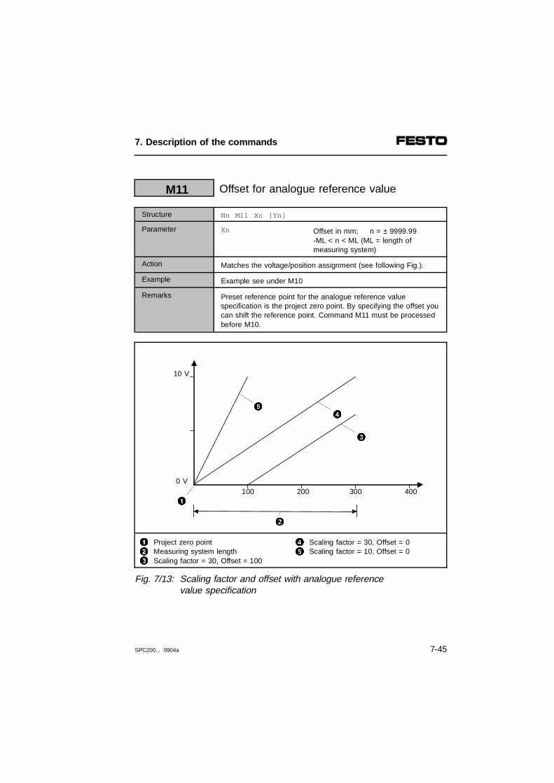
M11 Offset for analogue reference value
Structure Nn M11 Xn [Yn]
Parameter Xn Offset in mm; n = ± 9999.99 -ML < n < ML (ML = length ofmeasuring system)
Action Matches the voltage/position assignment (see following Fig.).
Example Example see under M10
Remarks Preset reference point for the analogue reference valuespecification is the project zero point. By specifying the offset youcan shift the reference point. Command M11 must be processedbefore M10.
123
Project zero pointMeasuring system lengthScaling factor = 30, Offset = 100
45
Scaling factor = 30, Offset = 0Scaling factor = 10, Offset = 0
Fig. 7/13: Scaling factor and offset with analogue reference value specification
100
10 V
200 300 4000 V
4
1
5
3
2
7. Description of the commands
SPC200... 9904a 7-45

M12 Deactivate analogue input
Structure Nn M12 X [Y, Z, U]
Parameter X Axis designation
Action All the axes named will be stopped.The input for analogue reference value specification is deactivated.
Example Example see under M10
Remarks In modes 0 and 1, the analogue input must be deactivated withM12 before it is activated again with M10.
7. Description of the commands
7-46 SPC200... 9904a
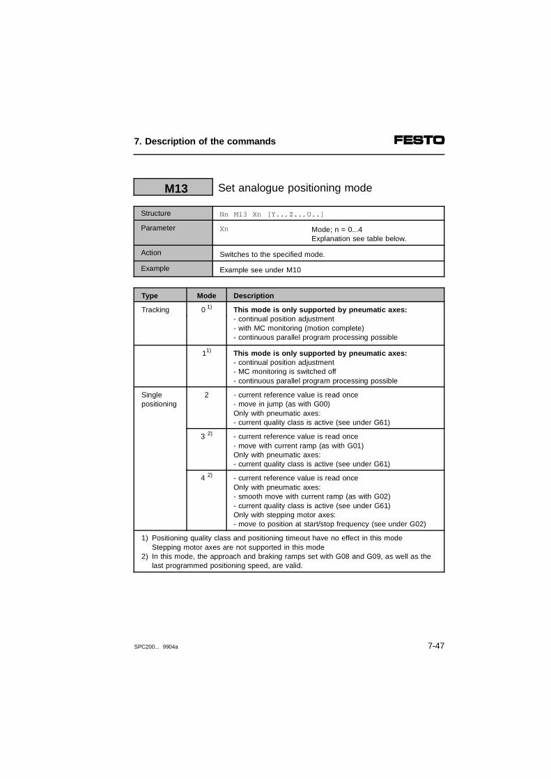
M13 Set analogue positioning mode
Structure Nn M13 Xn [Y..,Z..,U..]
Parameter Xn Mode; n = 0...4Explanation see table below.
Action Switches to the specified mode.
Example Example see under M10
Type Mode Description
Tracking 0 1) This mode is only supported by pneumatic axes:- continual position adjustment- with MC monitoring (motion complete) - continuous parallel program processing possible
11) This mode is only supported by pneumatic axes:- continual position adjustment- MC monitoring is switched off - continuous parallel program processing possible
Singlepositioning
2 - current reference value is read once - move in jump (as with G00) Only with pneumatic axes:- current quality class is active (see under G61)
3 2) - current reference value is read once- move with current ramp (as with G01) Only with pneumatic axes:- current quality class is active (see under G61)
4 2) - current reference value is read onceOnly with pneumatic axes: - smooth move with current ramp (as with G02) - current quality class is active (see under G61) Only with stepping motor axes:- move to position at start/stop frequency (see under G02)
1) Positioning quality class and positioning timeout have no effect in this mode Stepping motor axes are not supported in this mode
2) In this mode, the approach and braking ramps set with G08 and G09, as well as the last programmed positioning speed, are valid.
7. Description of the commands
SPC200... 9904a 7-47
M14 Assign analogue input
Structure Nn M14 Xn [Y..,Z..,U..]
Parameter Xn Number of differential inputn = 1...4
Action The analogue input module type SPC200-2AI-U has tworeference value inputs (differential inputs).reference value module no. 1: reference value inputs 1 and 2reference value module no. 2: reference value inputs 3 and 4With command M14, one or several axes can be assigned toeach differential input.
Example N007 M14 X2 U1 ;the X-axis is assigned to reference;value input 2 ;the U-axis is assigned to reference;value input 1
7. Description of the commands
7-48 SPC200... 9904a

M30 End program with repeat
Structure Nn M30
Parameter none
Action This command must be used to mark the end of programs. Itcauses the program to be continued at the first NC record.
Example N007 G00 X100N008 M30
;Move to position X100 ;Terminate program
Remarks Subprogram end see under M02
Pneu. axis Set mass percentageM37
Structure Nn M37 Xn [Y..,Z..,U..]
Parameter Xn Take into consideration the mass loadin % of the specified working load; n = 0...990=100 %, 1=1 %.....99=99 %
Action Sets controller to the specified load.
Example Nn M37 X50 ;Load = 50 % of the specified working;load
Remarks The work load is an application parameter. This command will bestored and supports positioning with different work loads.
Recommendation: Carry out the dynamic identification withminimum and maximum work load if you wish to use thisNC record.
7. Description of the commands
SPC200... 9904a 7-49

M38 Load actual value into position register
Structure Nn M38 @n X [Y, Z, U]
Parameter @n Register number n = 0...99
Action The current position is loaded into the specified position register.
Example N003 G00 G91 X100N004 M38 @1 X
N005 G29 @0 X@1
N006 G00 G90 X@0
;Move relative by 100 mm;Load current position into;position register 1 of the X axis;Form the sum of the two position ;registers 0 and 1, Store result in;position register 0;Move to position in Register 0
M39 Reserved for later expansions
Structure
Parameter
Action
Example
Remarks
7. Description of the commands
7-50 SPC200... 9904a

L Access subroutine (load subroutine)
Structure Nn LnorNn LRn
Parameter n
Rn
Program numbern = 0...99Register numbern = 0...99
Action Access the given program as subroutine.
Example See below
Remarks The program number can be specified directly (n) or indirectly viaa register (Rn). Nesting depth = 4
PalletizingExample
12
Distance between rowsPositions
Fig. 7/14: Palletizing
0 mm
250 mm50 mm
200 mm
2
1
7. Description of the commands
SPC200... 9904a 7-51
Program 0
...N003 G28 @1 X200 ;Load topmost pallet rowN004 G28 @2 X50 ;Load distance between rowsN005 #LR0=0 ;Initialize number of rowsN006 L1 ;Call Program 1N007 #AR0=1 ;Update counterN008 #TR0=0 10 ;Column filled?N009 E05 6 ;Jump to N006.... ;further commands.... N080 M30 ;End of program
Subprogram 1 Fill pallet gap
N000 #TNI0.0 0 ;Wait for partN001 G00 X0 ;Fetch part, position 0 mmN002 #SQ0.0 ;Close grips N003 G00 X@1 ;Move to pallet positionN004 #RQ0.0 ;Open grips, deposit partN005 G29 @1 X@2 ;Calculate next position.... ;Further commands....N016 M02 ;End of subroutine
Position register @1 contains the current pallet position.Position register @2 contains the distance betweenrows. These position registers are initialized in linesN003 and N004 (program 0).
Register R0 serves as a loop counter and is initializedwith the number of rows. Subprogram 1 is accessed 6times and the current pallet gap is filled.
7. Description of the commands
7-52 SPC200... 9904a
E05 Unconditional jump
Structure Nn E05 n|Rn
Parameter n
Rn
NC record numbern = 0...99999R<Register number>Rn = R0...R99
Action The program run will always continue at the given jump mark.
Example N005 #TNI1.1 5N006 G00 X100N007 E05 5
;Wait for 1-signal at input I1.1 ;Move to position X100 ;Jump to NC record 5
In NC record 7 the program always branches to NC record 5.
#S Set single-bit operand
Structure Nn #S<Operand>
Parameter <Operand> Permitted operands are single-bit operands, but no inputs.Flags: F0...F63Outputs: all freely programmable
Action The given single-bit operand is set.
Example N10 #SQ0.0 ;Set output Q0.0
After this record has been processed the output Q0.0 provides a1-signal.
Remarks Certain outputs are reserved by previously stored functions.Flags are remanent.
7. Description of the commands
SPC200... 9904a 7-53

#R Reset single-bit operand
Structure Nn #R<Operand>
Parameter <Operand> Permitted operands are single-bit operands, but not inputs.Flags: F0...F63Outputs: all freely programmable outputs
Action The given single-bit operand is reset.
Example N10 #RQ0.0 ;Reset output Q0.0
After this record has been processed the output Q0.0 provides a0-signal.
Remarks Certain outputs are reserved by previously stored functions.Flags are remanent.
#T Test single-bit operand for 1-signal
Structure Nn #T<Operand> <Record number>
Parameter <Operand>
<Record number>
All single-bit operands are permitted.Flags: F0...F63Permitted inputs:all available inputsPermitted outputs:all available outputs
Specification of record number asnumerical value or as register number.<Record number> = 0...999or<Record number> = R0...R99
Action If the single-bit operand supplies a 1-signal, the program willbranch to the given NC record. Otherwise the following NC recordwill be processed.
Example see below
Remarks see also under "Test register".
7. Description of the commands
7-54 SPC200... 9904a

For this example, the following apply:Operating mode: start/stop
Example
In the following example binary-coded position numbersare sent to the SPC200 through the inputs I0.0 andI0.1. This allows four position numbers to be preset:
I0.1 I0.0 Positions
0 0 Po_1
0 1 Po_2
1 0 Po_3
1 1 Po_4
At the start of the program, the programmed stop isused to effect synchronisation with the host SPC. TheSYNC signal also allows the outputs of the SPC for thebinary-coded position numbers to be controlled simul-taneously. For this purpose, a debounce time of 30 msis preset in NC record 1.
N000 M00 ;Waits for SYNC signalN001 G04 3 ;Debounce time 30 msN002 #TI0.1 8 ;Po_3 or Po_4, if 1-signalN003 #TI0.0 6 ;Po_2, if 1-signalN004 G00 X@Po_1 ;Po_1, if both inputs 0N005 E05 0 ;ReboundN006 G00 X@Po_2 ;Po_2, if 1-signal only on I0.0N007 E05 0 ;ReboundN008 #TI0.0 11 ;Po_4, if both inputs 1N009 G00 X@Po_3 ;Po_3, if 1-signal only on I0.1N010 E05 0 ;ReboundN011 G00 X@Po_4 ;Po_4, if both inputs 1N012 E05 0 ;Rebound
7. Description of the commands
SPC200... 9904a 7-55

#TN Test single-bit operand for 0-signal
Structure Nn #TN<Operand> <Record number>
Parameter <Operand>
<Record number>
All single-bit operands permitted.Flags: F0...F63Permitted inputs:all available inputsPermitted outputs:all available outputs
Specification of the record number asa numerical value or as a registernumber.<Record number> = 0...999or<Record number> = R0...R99
Action If the single-bit operand supplies a 0-signal, the program willbranch to the given NC record. Otherwise the following NC recordwill be processed.
Example N30 #TNI0.0 30 ;Wait until I0.0 supplies a 0-signal
#LR Load register
Structure Nn #LR<Register number>=n
Parameter <Register number>
n
Register number = 0...99
Value or register:n = - 32767...32767orn = R0...R99
Action The value given by n is loaded into the register.
Example N011 #LR1=100 ;Load value 100 into Register R1
Remarks Registers are remanent
7. Description of the commands
7-56 SPC200... 9904a

#AR Add to register
Structure Nn #AR<Registernummer>=n
Parameter <Register number>
n
Register number = 0...R99
Value or register:n = - 32767...32767orn = R0...R99
Action The contents of the register will be added to the given value.
Example N010 #LR0=0N011 #AR0=1
;Cancel register 0;Increment register 0 by 1
Remarks Registers are remanent
#TR Test register
Structure Nn #TR<Registernummer>=n <Record number>
Parameter <Register number>
n
<Record number>
Register number = 0...99
Value or register:n = - 32767...32767orn = R0 ... R99
Value or register:<Record number> = 0...999or<Record number> = R0...R99
Action If the register contains the given value, branch to NC record n.
Example N10 #TR0=100 350 ;If Register 0 =100, jump to NC ;record 350
If register 0 holds the value 100, the program will branch to NCrecord 350.
7. Description of the commands
SPC200... 9904a 7-57

7. Description of the commands
7-58 SPC200... 9904a

Chapter 8
Diagnosis and error treatment
8. Diagnosis and error treatment
SPC200... 9904a 8-1

Contents
8. Diagnosis and error treatment
8.1 On-the-spot dagnosis .................................................................... 8-48.2 Error messages on the control panel ............................................ 8-98.3 Eliminating errors on the system................................................. 8-248.3.1 Errors when the system is switched on ...................................... 8-248.3.2 Errors in positioning..................................................................... 8-25
8. Diagnosis and error treatment
8-2 SPC200... 9904a
The SPC200 offers extensive and user-friendly possi-bilities for diagnosis and error treatment. The followingpossibilities are available:
Contents ofthis chapter
– The LEDs on the SPC200 and on the connected fielddevices show directly configuration errors, hardwareerrors, string errrors, etc.
– The control panel shows detailed error messagescoded in the form of a hexadecimal number. Theseerror messages describe in detail the error class, theerror number and give additional information for loca-lizing the error (see section 8.2).
WinPISA shows error messages in plain text in onlinemode. Information on the LED functions of the field busand stepping motor indexer module can be found in themanual for the relevant module.
Further infor-mation
A description of the time behaviour of the I/O signalswhen errors are acknowledged can be found in Chapter5.
8. Diagnosis and error treatment
SPC200... 9904a 8-3

8.1 On-the-spot dagnosis
The LEDs on the power supply module, the axis inter-face and on the I/O modules (optional) give informationabout the operating status of the system. The followingtables show how the various operating states are indi-cated by the LEDs. The meaning of the displays is asfollows:
LED Meaning
LED lights up
LED out
LED flashes - continuously without a break
or- several times with break (flash sequence
corresponding to the error class occuring with a 1 second break, see also section 8.2)
LED on the SPC200 Smart Positioning Controller
Reaction Sequence Operating status Error remedy
POWER LED
Operating voltage applied None
Operating voltage not applied • Check operating voltageconnection of electroniccomponents (pin 2).
ON
OFF
ON
OFF
8. Diagnosis and error treatment
8-4 SPC200... 9904a
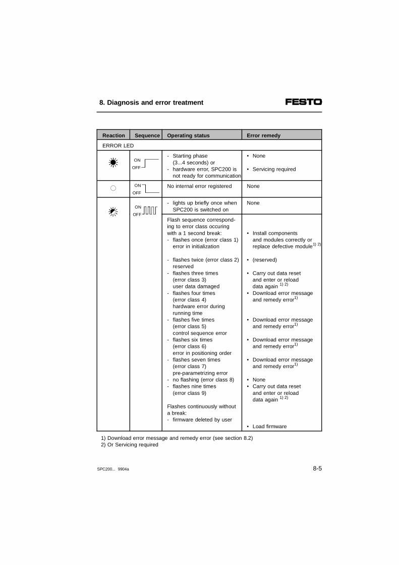
Reaction Sequence Operating status Error remedy
ERROR LED
- Starting phase (3...4 seconds) or
- hardware error, SPC200 is not ready for communication
• None
• Servicing required
No internal error registered None
- lights up briefly once whenSPC200 is switched on
None
Flash sequence correspond-ing to error class occuringwith a 1 second break:- flashes once (error class 1)
error in initialization
- flashes twice (error class 2)reserved
- flashes three times (error class 3) user data damaged
- flashes four times (error class 4) hardware error during running time
- flashes five times (error class 5)control sequence error
- flashes six times (error class 6) error in positioning order
- flashes seven times (error class 7) pre-parametrizing error
- no flashing (error class 8)- flashes nine times
(error class 9)
Flashes continuously withouta break:- firmware deleted by user
• Install components and modules correctly orreplace defective module1) 2)
• (reserved)
• Carry out data resetand enter or reload data again 1) 2)
• Download error message and remedy error1)
• Download error message
and remedy error1)
• Download error message and remedy error1)
• Download error messageand remedy error1)
• None• Carry out data reset
and enter or reload data again 1) 2)
• Load firmware
1) Download error message and remedy error (see section 8.2) 2) Or Servicing required
ON
OFF
ON
OFF
ON
OFF
8. Diagnosis and error treatment
SPC200... 9904a 8-5

LED on the axis interface
Reaction Sequence Operating status Error remedy
POWER LED
Operating voltage applied None
No operating voltage present Check operating voltage andload voltage connection onthe SPC200 (Pin 1 and Pin 2).
ERROR LED
- Starting phase (3...4 seconds) or
- hardware error, SPC200 is not ready for communication
• None
• Servicing required
- No internal errorregistered
None
- lights up briefly whenSPC200 is switched on
None
Flashes at 1 second intervals:- once (error number 1)
axis interface has not beeninitialized
- twice (error number 2)a CAN module on the busis in the OFF status
- three times (error number 3)incorrect type ID loaded
- four timesemergency stop is activated
- five timeslinear potentiometer is inend position or is notconnected
- six times timeout- seven times
load voltage too low
• Switch on system again,if necessary, replace defective axis interface
• Switch on system again,if necessary, replacedefective CP module
• Remove non-permitted module or servicing required
• None
• Bring linear potentiometerout of end positionor connect
• Servicing required• Check load voltage
ON
OFF
ON
OFF
ON
OFF
ON
OFF
ON
OFF
8. Diagnosis and error treatment
8-6 SPC200... 9904a

LEDs on the I/O function module
The operating status of the input module is indicated bythe status LED (POWER/DIAG) on the I/O functionmodule. The displays mean:
Status LED
Reaction Sequence Operating status Error remedy
POWER/DIAG (status LED)
Operating voltage applied None
- Operating voltage not appliedor
- no connection to the SPC200
• Check CP cable andoperating voltage and loadvoltage connections onthe SPC200 (pins 1 and 2).Switch on SPC200 againor carry out system reset
- Test phase when power supply is switched onor
- short circuit in sensor supply
• None
or• eliminate short circuit
and acknowledge error 1)
1) The error is cancelled when the operating voltage for the SPC200 is switched on.
ON
OFF
ON
OFF
ON
OFF
8. Diagnosis and error treatment
SPC200... 9904a 8-7
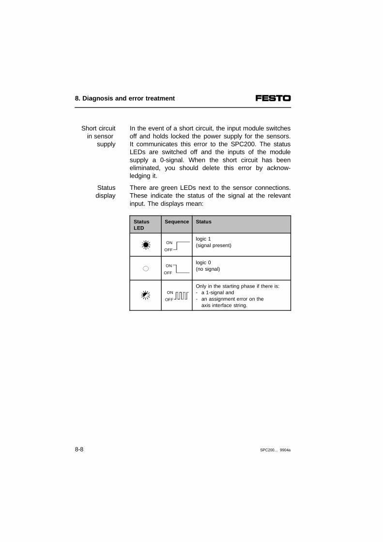
In the event of a short circuit, the input module switchesoff and holds locked the power supply for the sensors.It communicates this error to the SPC200. The statusLEDs are switched off and the inputs of the modulesupply a 0-signal. When the short circuit has beeneliminated, you should delete this error by acknow-ledging it.
Short circuitin sensor
supply
There are green LEDs next to the sensor connections.These indicate the status of the signal at the relevantinput. The displays mean:
Statusdisplay
StatusLED
Sequence Status
logic 1(signal present)
logic 0(no signal)
Only in the starting phase if there is:- a 1-signal and- an assignment error on the
axis interface string.
ON
OFF
ON
OFF
ON
OFF
8. Diagnosis and error treatment
8-8 SPC200... 9904a

8.2 Error messages on the control panel
If errors occur, the control panel will show detailed errormessages (error codes) coded in the form of a hexade-cimal number. The coded error messages contain infor-mation on:
– the error class
– the error number
– in some cases additional information
Structure of the error messages
The control panel shows error messages in the form ofan eight-position hexadecimal number. The individualpositions of this hexadecimal number contain the follow-ing information:
12
Error class (0...9)Axis identifier (0...4)
34
Error numberAdditional information
Fig. 8/1: Structure of the error messages (error code)
0 00 00 0 0 0
234 1
8. Diagnosis and error treatment
SPC200... 9904a 8-9

The error class describes the type of error which hasoccurred (e.g. hardware error, configuration error etc.).If the SPC200 is ready for communication, the ERRORLED will flash according to the relevant error class.
Error class
In the case of errors concerning the axis, the axisidentifier indicates the axis on which the error hasoccurred. The identifiers mean:
Axisidentification
Axisidentification
Meaning
0 Error is not axis-related (system error)
1 Error on X-axis
2 Error on Y-axis
3 Error on Z-axis
4 Error on U-axis
The error number indicates the source of the error. Withsome error numbers, additional information is output asa three-position hexadecimal number which containsfurther important instructions on localizing the error.
Error number and
additionalinformation
8. Diagnosis and error treatment
8-10 SPC200... 9904a

Error stages
All errrors are assigned to a certain error stage. Theerror stage specifies how the error can be acknow-ledged and how the system reacts when the erroroccurs and is acknowledged.
Errorstage
Error reaction 1) Reaction to acknowledgement 2)
A Serious system error in the initialization phase
- Controller remains switched off- The following outputs remain
reset:READY, ACK_A/B
- Initialization phase
You must switch on again, in somecases a system reset is possible
B Serious system error in the operating phase
- Controller remains switched off- The following outputs will be
reset:READY, ACK_A/B,
- Controller is switched on- Status of outputs is restoredError must be eliminated andacknowledged 3)
C System error or user error in the operating phase
- Sequence is stopped- The following outputs
are reset:READY, ACK_A/B
- Sequence can be started- Status of outputs is restoredError must be eliminated andacknowledged 3)
D Simple user upload/download or executing error
- Error code is entered- System remains fully operational
Error code is deleted
1) With stage A to C: ERROR LED flashes and error code is entered 2) With stage A to C: error code and ERROR LED are deleted3) Error acknowledgement by start signal (start/stop mode) or CLK signal (record select
mode) or by Reset command (Reset Error, Reset Program, Reset System)
8. Diagnosis and error treatment
SPC200... 9904a 8-11

The following tables explain all the error messagessorted according to error classes and show the relatederror stages.
Errorclass
Error message
Operating status Error remedy
0 00000000 No error registered
1
(A)
zzzyyx01 Starting phase: error in initialization of components and modules
sss01001 Internal system error • Servicingrequired
sss02001 Errors in initializing the axis interface string
zzz=Additional information (1...D or 11...1D)1....D : error on 1st. AIF string1 or B : error on first measuring system2 or C : error on second measuring system3 or 9 : error on first AIF4 or A : error on second AIF5 : error on first CP module6 : error on second CP module7 or 8 or D : bus error 11....1D : error on 2nd. AIF string11 or 1B : error on first measuring system12 or 1C : error on second measuring system13 or 19 : error on first AIF14 or 1A : error on second AIF15 : error on first CP module16 : error on second CP module17 or 18 or 1D : bus error
• Check modulesand compo-nents on theaxis interface string and remove ifnecessary
(A) = error stage, zzz = additional information, yy = error number, x = axis identifiersss = additional information for service personnel, AIF = axis interface string
8. Diagnosis and error treatment
8-12 SPC200... 9904a

Errorclass
Error message
Operating status Error remedy
0 00000000 No error registered
1
(A)
zzzyyx01 Starting phase: error in initialization of components and modules
zzz03001 Defective or non-permittedcomponentzzz=Slot number 2)
• Replace or removecomponent
00004001 Actual configuration not thesame as nominal configuration
• Check configuration ofinternal components and string assignment orcorrect and switch onSPC200 again or carryout system reset,
or• save actual configuration as
nominal configuration (menu SET CONFIGUR.) orload project (with WinPISA)
ZZZ05x01 Initialization error with anintelligent module 1)
x = 0: initialization errorx = 1...4: axis 1 (X) ...4 (U)x = 5: field bus module zzz = slot number 2)
• Check stepping motorindexer modul, subcontroller and field bus module and switch on SPC200 again or carry out a system reset
or servicing required
2 zzzyyx02 Reserved
Reserved
(A) = error stage, zzz = additional information, yy = error number, x = axis identifiersss = additional information for service personnel, ppp = program number1) Stepping motor module, field bus module or axis interface module2) Ascending from left to right (0...3 with 4 slots or 0...5 with 6 slots)
8. Diagnosis and error treatment
SPC200... 9904a 8-13
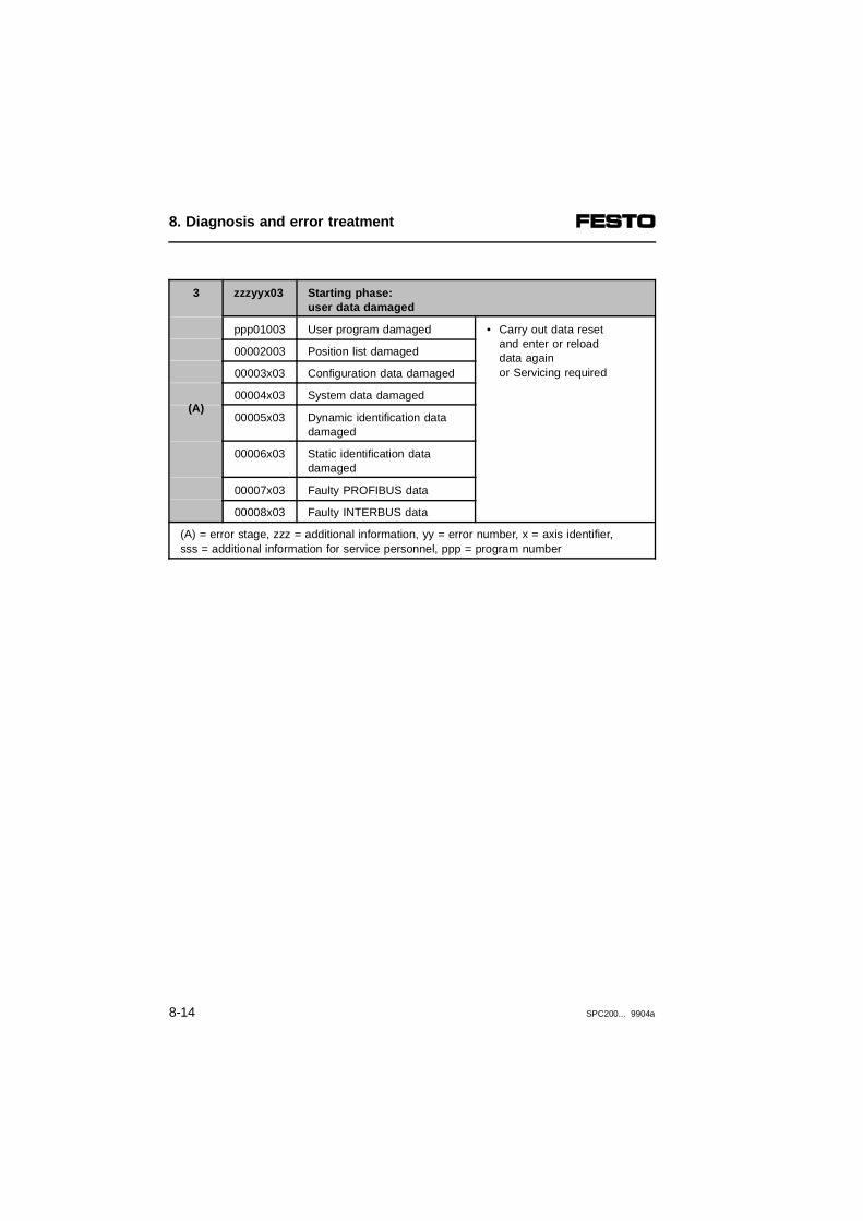
3
(A)
zzzyyx03 Starting phase: user data damaged
ppp01003 User program damaged • Carry out data resetand enter or reload data again or Servicing required
00002003 Position list damaged
00003x03 Configuration data damaged
00004x03 System data damaged
00005x03 Dynamic identification datadamaged
00006x03 Static identification datadamaged
00007x03 Faulty PROFIBUS data
00008x03 Faulty INTERBUS data
(A) = error stage, zzz = additional information, yy = error number, x = axis identifier,sss = additional information for service personnel, ppp = program number
8. Diagnosis and error treatment
8-14 SPC200... 9904a

Error class
Errormessage
Operating status Error remedy
4
(C)
(B)
(B)
(C)
(C)
zzzyyx04 Hardware error during running time
sss01004 Internal system error • Servicing required
sss02004 AIF string no longer functions 1)
zzz as with error class 1, errornumber 2)
• Check modules on AIF string and string assignment 1)
sss03x04 AIF string no longer functionsor measuring system in endposition or measuring systemcable defective1)
zzz as with error class 1, errornumber 2)
• Check modules on AIF string and string assignment or bringmeasuring system outof end position or replacemeasuring system cable1)
zzz04004 Error on first I/O modulezzz=short circuit at input (I) oroutput (Q) or undervoltage000: short circuit at I and Q
and undervoltage001: short circuit at I and Q002: short circuit at I and Q
and undervoltage003: short circuit at I004: short circuit at Q
and undervoltage005: short circuit at Q006: undervoltage
• Eliminate undervoltageor short circuit 2)
zzz05004 Error on second I/O modulezzz=short circuit at input oroutput or undervoltage000 to 006: additionalinformation as with error no.zzz04004
• Eliminate undervoltageor short circuit
(B), (C) = Error stage, zzz = additional information, yy = error number, x = axis identifier, sss = additional information for service personnel1) When this error is rectified and quitted, the system tries first of all to start the axis
interface string. If this is not possible, the axis interface string will be re-initialized.This procedure may take a certain amount of time, depending on the systemconfiguration used (max. 10 sec.).
2) If there is a short circuit at the input, the operating voltage must be switched onagain.
8. Diagnosis and error treatment
SPC200... 9904a 8-15

Errorclass
Error message
Operating status Error remedy
4
(B)
(C)
(C)
(C)
(C)
(C)
(C)
zzzyyx04 Hardware error during running time
00006x04 Load voltage for field devicesand proportional directionalcontrol valve too low 1)
• Eliminate undervoltageat operating voltageconnection (X2) 1)
00007004 Fault in field bus module • Insert module fully or replace
zzz08004 Error at analogue referencevalue modulezzz:= Error type001: Time-Out A/D converter002: Upper software end
position exceeded003: Lower software end
position exceeded
• Replace component• Adapt voltage range to
defined positioning range
zzz09004 Error at the V.24 interface (X4)zzz:= Error type001: Overrun002: Parity error
• Check diagnostic moduleor connecting cable;or use lower baud rate
zzz0A004 Error at the V.24 interface forthe control panel (X3) zzz:= Error type001: Overrun002: Parity error
• Check diagnostic moduleand control panel
zzz0B004zzz0C004
Fault in:- second I/O module (B)– third I/O module (C)(zzz as with error class 4,error numbers 4 and 5
• Eliminate undervoltage orshort circuit2)
zzz0D004 Fault in AIF module(for 2nd AIF string)
• Insert module fully or replace
(C) = Error stage, zzz = additional information, yy = error number, x = axis identifier 1) When this error is eliminated and acknowledged the axis interface string will be
reinitialized. This process can take a certain amount of time.
8. Diagnosis and error treatment
8-16 SPC200... 9904a
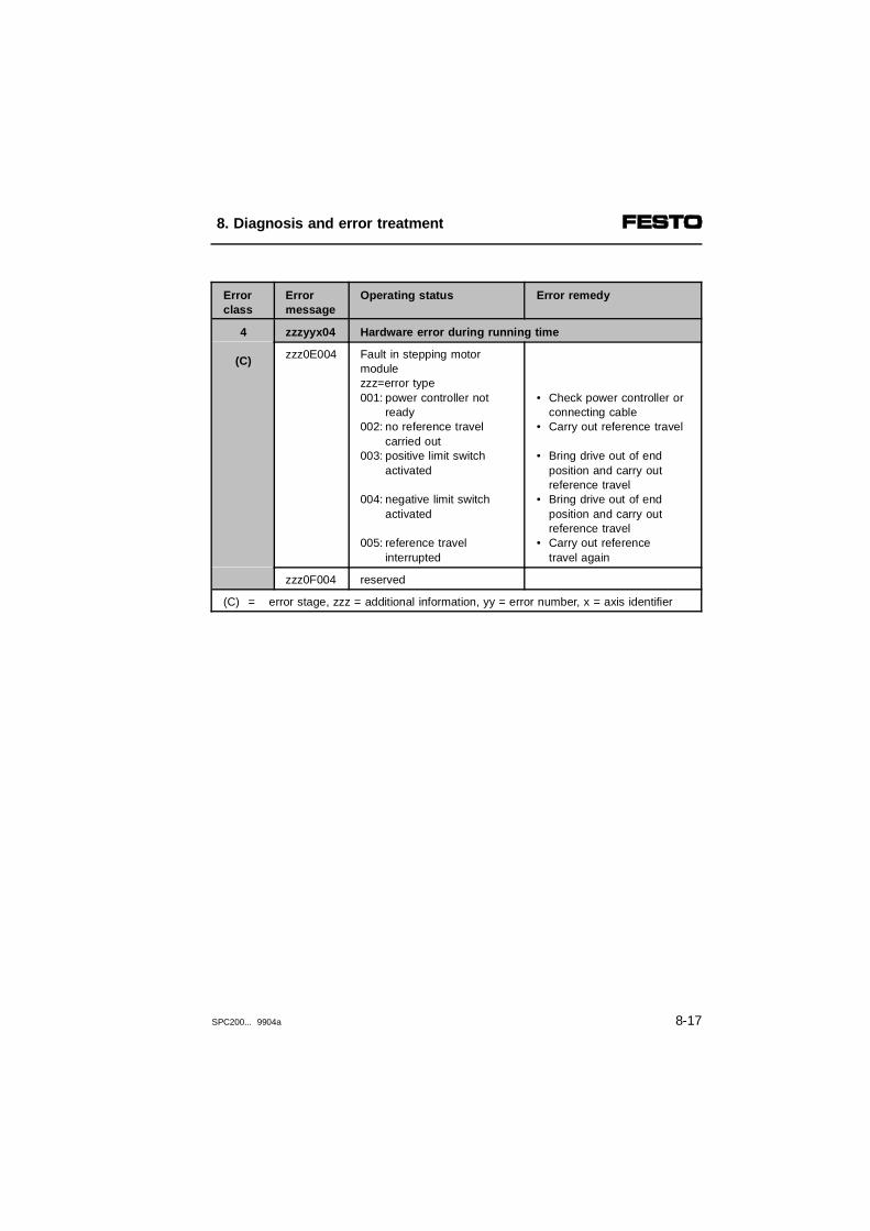
Errorclass
Errormessage
Operating status Error remedy
4
(C)
zzzyyx04 Hardware error during running time
zzz0E004 Fault in stepping motor modulezzz=error type 001: power controller not
ready002: no reference travel
carried out 003: positive limit switch
activated
004: negative limit switchactivated
005: reference travelinterrupted
• Check power controller orconnecting cable
• Carry out reference travel
• Bring drive out of end position and carry out
reference travel• Bring drive out of end
position and carry out reference travel
• Carry out referencetravel again
zzz0F004 reserved
(C) = error stage, zzz = additional information, yy = error number, x = axis identifier
8. Diagnosis and error treatment
SPC200... 9904a 8-17

Errorclass
Errormessage
Operating status Error remedy
5
(C)
zzzyyx05 Sequence control errrors
ppp01005 Start program does not exist • Correct start programnumber or load/enterstart program
nnn02005 Subprogram does not exist (L command)
• Correct NC record orload/enter program
nnn03005 NC record does not exist • Correct NC record
nnn04005 Program no. with L commandis identical to number of accessing program
• Correct NC record
nnn05005 Permitted nesting depth exceeded with L command
• Correct NC record
nnn06005 Analogue mode active withNC commands G00, G01,G02 or M10
• Correct NC record
nnn07005 Arithmetical overrun in aregister (R)
• Correct NC record
nnn08005 Record overrun • Conclude programs withcommand M02 or M30
(C) = error stage, zzz = additional information, yy = error number, x = axis identifier,ppp = program number, nnn = NC record number of the NC command causing the
overrun
8. Diagnosis and error treatment
8-18 SPC200... 9904a

Errorclass
Errormessage
Operating status Error remedy
6
(C)
nnnyyx06 Error in positioning task
nnn01x06 Time-out, position cannot bereached quickly enough (MC error)
• Remove obstruction in positioning range or checksupply pressure or increasepositioning time-out oroptimize controller
nnn02x06 Reference position outside the software end positions;the positioning process is notstarted
• Correct NC record, positionlist or software end positions
nnn03x06 Non-permitted positioning task with position-dependentrecord indexing (G25)
• Correct NC record or position list (see under NC command "G25").
nnn04x06 Required speed is not reached • Correct maximum speedor speed factor
sss05x06 Error in identification travel • Check configurationand supply pressure
nnn06x06 NC command G00 notpossible, as dynamic identification has not beencarried out
• Carry out dynamic identification
nnn07x06 Controller in SPC200 cannotbe initialized
• Check controller, axis andapplication parameters
(C) = error stage, zzz = additional information, yy = error number, x = axis identifier,nnn = NC record number of the NC command causing this error
8. Diagnosis and error treatment
SPC200... 9904a 8-19

Errorclass
Errormessage
Operating status Error remedy
6
(C)
(C)
(C)
(B)
(B)
(C)
(C)
zzzyyx06 Error in positioning task
nnn08x06 Task cannot be accepted • Correct NC record or stop system beforecarrying out activity
nnn09x06 Contents of a position registernot valid
• Correct NC record
nnn0Ax06 reserved reserved
0000Bx06 Identification aborted as there is no enable signal
• Set ENABLE input and start identification again
nnn0Cx06 Axis oscillates (control not stable)nnn=NC record number if aprogram is active
• Check controller, axis andapplication parameters
nnn0Dx06 Bad positioning qualitynnn=NC record number if a program is active
• Check controller, axis andapplication parameters
0000Ex06 Identification data not valid • Carry out identificationagain
nnn0Fx06 Non-permitted positioningquality class
• Correct NC record
(B), (C) = error stage, zzz = additional information, yy = error number, x = axis identifier,nnn = NC record number of the NC command causing this error
8. Diagnosis and error treatment
8-20 SPC200... 9904a

Errorclass
Errormessage
Operating status
6
(C)
zzzyyx06 Error in positioning task
nnn10x06 With pneumatic axis:- Controller is inactive as
there is no enable signal for firstcommissioning or configurationis faulty
With stepping motor axis:- no enable signal from
power controller
• Create positive edge at ENABLE input or check controller, axis andapplication parameters
• Correct error in powercontroller
nnn11x06 Command not supported by thisaxis type.With pneumatic axes:- command reference travel (G74)With electric axes:- activate analogue input in
modes 0 and 1 (M10);- command M39
• Correct NC program
nnn12x06 Reference position for this axisunknown
• Carry out referencetravel
7
(C)
zzzyyx07 Error in pre-parametrizing
00001x07 Software end position lies outsidepossible positioning range
• Correct parameter(permitted value rangessee chapter 5)
00002x07 Mass load lies outside permittedrange
00003x07 Gain factor not permitted
00004x07 Damping factor not permitted
00005x07 Filter factor not permitted
00006x07 Measuring system length notvalid or measured valueoutside set cylinder length
00007x07 Parameter limit exceeded
00008x07 Measuring system type notpermittted
(C), (D) = error stage, zzz = additional information, yy = error number, x = axis identifierppp = program number, nnn = NC record number of the NC command causing this error
8. Diagnosis and error treatment
SPC200... 9904a 8-21
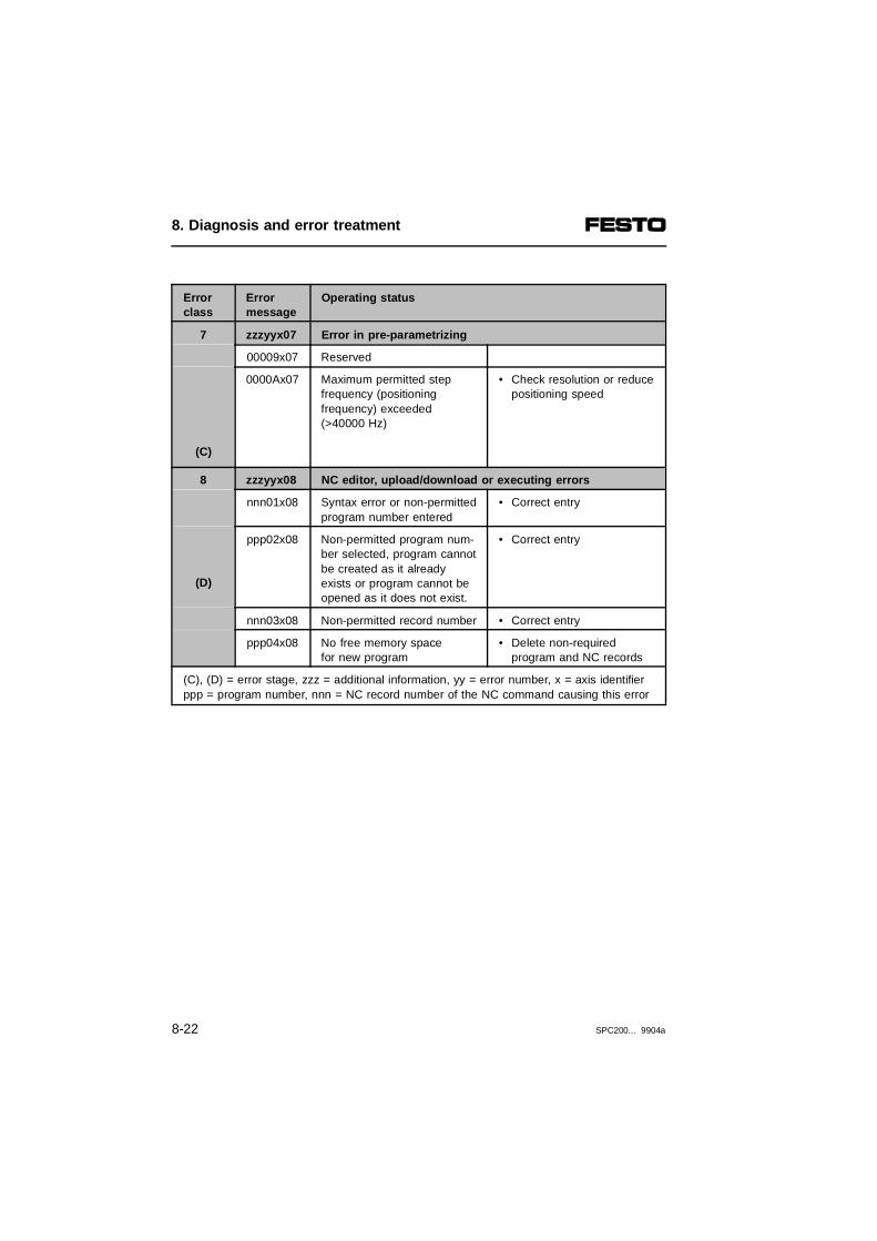
Errorclass
Errormessage
Operating status
7
(C)
zzzyyx07 Error in pre-parametrizing
00009x07 Reserved
0000Ax07 Maximum permitted step frequency (positioning frequency) exceeded (>40000 Hz)
• Check resolution or reducepositioning speed
8
(D)
zzzyyx08 NC editor, upload/download or executing errors
nnn01x08 Syntax error or non-permittedprogram number entered
• Correct entry
ppp02x08 Non-permitted program num-ber selected, program cannotbe created as it alreadyexists or program cannot beopened as it does not exist.
• Correct entry
nnn03x08 Non-permitted record number • Correct entry
ppp04x08 No free memory spacefor new program
• Delete non-required program and NC records
(C), (D) = error stage, zzz = additional information, yy = error number, x = axis identifierppp = program number, nnn = NC record number of the NC command causing this error
8. Diagnosis and error treatment
8-22 SPC200... 9904a
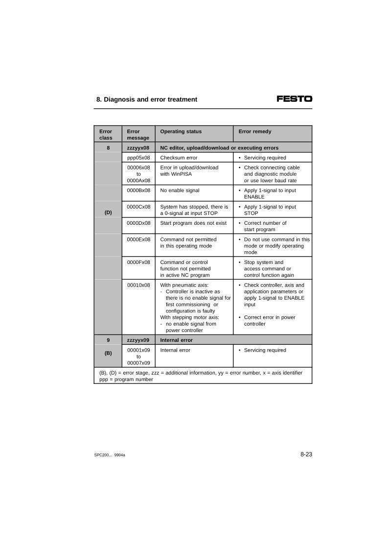
Error class
Errormessage
Operating status Error remedy
8
(D)
zzzyyx08 NC editor, upload/download or executing errors
ppp05x08 Checksum error • Servicing required
00006x08to
0000Ax08
Error in upload/downloadwith WinPISA
• Check connecting cableand diagnostic moduleor use lower baud rate
0000Bx08 No enable signal • Apply 1-signal to input ENABLE
0000Cx08 System has stopped, there isa 0-signal at input STOP
• Apply 1-signal to input STOP
0000Dx08 Start program does not exist • Correct number of start program
0000Ex08 Command not permittedin this operating mode
• Do not use command in thismode or modify operatingmode
0000Fx08 Command or control function not permittedin active NC program
• Stop system andaccess command or control function again
00010x08 With pneumatic axis:- Controller is inactive as
there is no enable signal forfirst commissioning or configuration is faulty
With stepping motor axis:- no enable signal from
power controller
• Check controller, axis andapplication parameters orapply 1-signal to ENABLEinput
• Correct error in powercontroller
9
(B)
zzzyyx09 Internal error
00001x09to
00007x09
Internal error • Servicing required
(B), (D) = error stage, zzz = additional information, yy = error number, x = axis identifierppp = program number
8. Diagnosis and error treatment
SPC200... 9904a 8-23
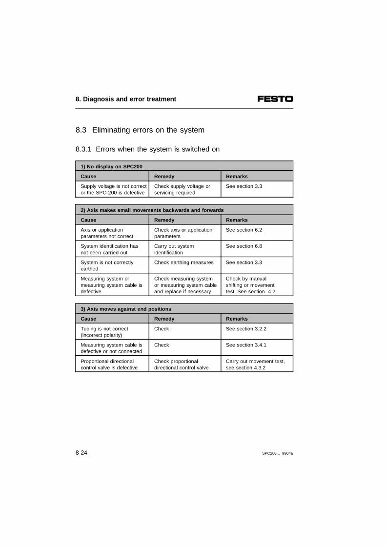
8.3 Eliminating errors on the system
8.3.1 Errors when the system is switched on
1) No display on SPC200
Cause Remedy Remarks
Supply voltage is not corrector the SPC 200 is defective
Check supply voltage orservicing required
See section 3.3
2) Axis makes small movements backwards and forwards
Cause Remedy Remarks
Axis or applicationparameters not correct
Check axis or application parameters
See section 6.2
System identification hasnot been carried out
Carry out systemidentification
See section 6.8
System is not correctlyearthed
Check earthing measures See section 3.3
Measuring system ormeasuring system cable isdefective
Check measuring systemor measuring system cableand replace if necessary
Check by manualshifting or movement test, See section 4.2
3) Axis moves against end positions
Cause Remedy Remarks
Tubing is not correct (incorrect polarity)
Check See section 3.2.2
Measuring system cable isdefective or not connected
Check See section 3.4.1
Proportional directional control valve is defective
Check proportionaldirectional control valve
Carry out movement test,see section 4.3.2
8. Diagnosis and error treatment
8-24 SPC200... 9904a

8.3.2 Errors in positioning
1) Drive does not move
Cause Remedy Remarks
No supply pressure Check
Valve cable not connectedcorrectly
Check See section 3.4.1
Proportional directional control valve is defective
Check and replaceif necessary
Carry out movement test, see section 4.3.2
2) Axis moves against end positions
Cause Remedy Remarks
Tubing is not correct Check See section 3.2.2
Measuring system cable isdefective or not connected
Check See section 3.4.1
Proportional directional control valve is defective
Check Carry out movement test, seesection 4.3.2
3) Axis has bad positioning behaviour
Cause Remedy Remarks
System is not mounted correctly
Check mechanicalparts
Check measuring system andcylinder for parallelity, mechanicalplay and sluggishness
System is not earthed correctly
Check See section 3.3.2
Application parameters arenot set optimally (mass, working stroke)
Check applicationparameters
See section 6.2
System identification hasnot been carried out
Carry out systemidentification
See section 4.3
Controller parameters arenot set optimally (gain, damping)
Optimize controllerparameters
See appendix A
8. Diagnosis and error treatment
SPC200... 9904a 8-25

8. Diagnosis and error treatment
8-26 SPC200... 9904a

Appendix A
Optimizing the positioning behaviour
A. Optimizing the positioning behaviour
SPC200... 9904a A-1

Contents
A. Optimizing the positioning behaviour
A.1 Basic information on control ..........................................................A-3A.2 Description of the controller factors...............................................A-6A.3 Optimizing the positioning behaviour ............................................A-9A.3.1 How to deal with an instable compressed air supply..................A-15
A. Optimizing the positioning behaviour
A-2 SPC200... 9904a

A.1 Basic information on control
The basis for controlling pneumatic axes is a model po-sitioning path incorporated in the SPC200. This modelfunctions on the assumption that there is a pneumaticaxis set up according to specifications, e.g. in respectof:
– the compressed air supply
– the valve-cylinder combination used
– the permitted mass load
– the size and length of tubing, etc.
The basic parameters of this positioning path are:
– the axis and application parameters to be entered
– internal data determined by the system identificationand by adaption.
By means of the system identification, variables suchas the attainable speed, acceleration capacity, frictionand the valve characteristics of the axis are determinedduring commissioning.
Systemidentification
During adaption, the positioning behaviour of the axis iscontinuously monitored while the system is operating.Internal controller parameters are adapted here to theactual status of the axis, e.g. in order to compensatefor system wear incurred during operation.
Adaption
A. Optimizing the positioning behaviour
SPC200... 9904a A-3

The SPC200 permits not only point-to-point positioning(G00), but also profile control (G01/G02) of pneumaticaxes.
In the case of point-to-point positioning, reference valuecurves are generated by the SPC200 for path, speedand acceleration. These values should enable repro-ducible no-overswing approach as fast as possible tothe reference position (see section 7.2.1, commandG00).
Point-to-point
With profile control, the reference value curves are cal-culated on the basis of the reference values pro-grammed by the user for position, speed and accelera-tion (see section 7.2.1, commands G01, G02).
Profile control
The reference positioning time is the sum of the individ-ual times for the following phases (see following diag-ram):
– acceleration phase
– braking phase
– constant movement phase
Please note that the programmed values for speed andacceleration are automatically limited by the positioningstroke to values which can actually be implemented.The maximum values which can be achieved are deter-mined individually for each axis during dynamic identifi-cation.
A. Optimizing the positioning behaviour
A-4 SPC200... 9904a
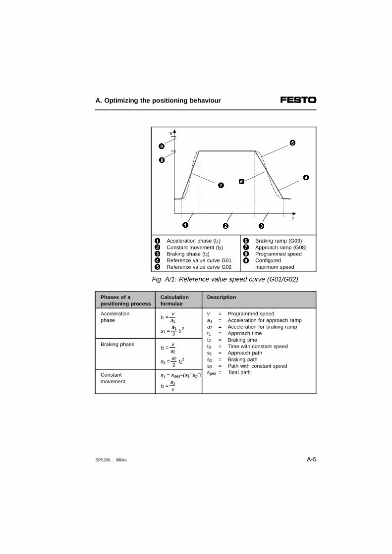
12345
Acceleration phase (t1)Constant movement (t3)Braking phase (t2)Reference value curve G01Reference value curve G02
6789
Braking ramp (G09)Approach ramp (G08)Programmed speedConfiguredmaximum speed
Fig. A/1: Reference value speed curve (G01/G02)
Phases of apositioning process
Calculationformulae
Description
Accelerationphase
t1 = va1
s1 = a1
2 t12
v = Programmed speeda1 = Acceleration for approach rampa2 = Acceleration for braking rampt1 = Approach timet2 = Braking timet3 = Time with constant speeds1 = Approach paths2 = Braking paths3 = Path with constant speedsges = Total path
Braking phaset2 =
va2
s2 = a2
2 t2
2
Constantmovement
s3 = sges−(s1+s2)
t3 = s3
v
9
1 2 3
4
5
67
8
v
t
A. Optimizing the positioning behaviour
SPC200... 9904a A-5

A.2 Description of the controller factors
The SPC200 determines various controller parametersfrom the basic parameters. These determine thedynamics (speed) as well as the transition behaviour(damping) of the control. The aim is to guarantee fastno-overswing positioning with few contour errors(dynamic control deviation).
The controller parameters calculated by the SPC200are therefore usually the optimum values. The (real)pneumatic axes used do not, however, always corre-spond to the (ideal) axes used as the basis for control.To take into consideration any possible deviations, youcan influence the controller parameters by entering fac-tors.
Instructions on optimizing the positioning behaviour canbe found in section A.3.
The SPC200 standardizes the factors to 1.0. Byincreasing the factors (>1), you can increase theparameters; by reducing the factors (<1), you cancorrespondingly reduce the parameters.
A. Optimizing the positioning behaviour
A-6 SPC200... 9904a

With the gain factor, you can influence the sensitivitywith which the closed loop positioning circuit reacts tomodifications of the measured variables (position,speed, acceleration).
Gainfactor
Behaviour of axis Factor
The drive tends towards instability(tendency to oscillate when positioning up toconstant swinging around the reference position).
Reduce
Bad positioning accuracy or high contour errorsas well as long positioning time.
Increase
The positioning process is carried out quickly andaccurately.
Optimum
Permitted 0.1 .. 10.0
Damping is a measure of the transition behaviour of thesystem from the actual to the reference status, espe-cially with fast modifications to the reference value. Thesystem should normally guarantee low-swing behaviourin response to reference value specification and no-overswing movement to the destination position.
Dampingfactor
By modifying the factor for damping, you can influencethe transition behaviour of the system
Behaviour of axis Factor
Bad positioning quality, reference position isreached only slowly (underswing).
Reduce
The drive tends towards instability (tendency to swinging when positioning up toconstant oscillation around the reference position,heavy overswing).
Increase
The positioning process is carried out quickly andaccurately.
Optimum
Permitted 0.1 .. 10.0
A. Optimizing the positioning behaviour
SPC200... 9904a A-7

Speed and acceleration are derived from the path sig-nal and are filtered to improve the signal quality. If sig-nal quality is bad in practice, e.g. due to electrical inter-ference, you can influence the filtering of the signal bymeans of the signal filter factor.
Signal filterfactor
If filtering is too strong, it may destabilize the control.
Behaviour of axis Factor
The drive tends towards instability (in spite of low amplification and good cushioning)
Reduce
"Noise" or loud valve noises (observe amplification, i.e too high)
Increase
The positioning process is carried out quickly andaccurately, low valve noises
Optimum
Permitted: 0.1 .. 10.0
A. Optimizing the positioning behaviour
A-8 SPC200... 9904a

A.3 Optimizing the positioning behaviour
The following problems may occur during positioning:
– axis stops several times prematurely
– swinging around the reference position
– stability problems, high frequent swinging around thereference position
– overswing
– underswing
Before starting to optimize the positioning behaviour ofthe axis, you should carry out the following steps:
• Make sure that the pneumatic axis is set up according to the specifications (see chapter 3).
• Make sure that all the axis and application parameters are set correctly.
• Always carry out the static identification and at leastone of the dynamic identifications.
• Let the axis perform several positioning cycles. This is to guarantee that the adaption is effective.
A. Optimizing the positioning behaviour
SPC200... 9904a A-9

If problems still occur, proceed as follows:
1. Observe the positioning behaviour. Make use hereof the software package WinPISA. With WinPISAyou can record and graphically represent referenceand actual values e.g. for path, speed and accelera-tion.
Detailed information on WinPISA can be found in theWinPISA user manual.
2. Compare the positioning behaviour or the graph cre-ated with WinPISA with the following examples.
3. Optimize the positioning behaviour as described inthe table for the relevant example. First check fromtop to bottom the most probable causes and theirremedies.
A. Optimizing the positioning behaviour
A-10 SPC200... 9904a

Effect Cause Remedy
Axis stops several times prematurely
- System identificationnot carried out
- Adaption not yetcompleted
- Bad running behaviour of cylinder/guide(stick-slip)
- Incorrect mass- Incorrect valve type
configured
• Carry out systemidentification
• Move a few positioning cycles (adaption)
• Check or carry outmaintenance orreplace components
• Correct mass• Correct configuration
Swinging around the reference position with standing times
- Static identification not carried out
- Incorrect mass loadconfigured or
programmed (M37)- Long service period of
cylinder (frictionhas changed)
- Gain factor settoo low
• Carry out static systemidentification
• Correct configurationor program
• Carry out identificationagain (static or dynamic)
• Correct parameter
12
Reference positionCurrent position
(t)
(s)
2
1
(t)
(s)
2
1
A. Optimizing the positioning behaviour
SPC200... 9904a A-11

Effect Cause Remedy
Stability problems, highly frequent swinging around the reference position
- Incorrect mass loadconfigured or programmed (M37)
- Gain factor settoo high
- Damping factor set too low- Filter set too high
(smooth acceleration/speed signal butconstant swinging)
- or loud noise withacceleration signalwith high amplitude
- Minimum mass loadnot reached
- Too low a tolerance demanded
• Correct configurationor program
• Correct parameter
• Correct parameter
• Reduce signal filter factor
• Increase signal filter factor
• Increase basic load(see chapter 3)
• Increase tolerance
123
Reference position Current positionSpeed
(t)
(s)
1
3
2
A. Optimizing the positioning behaviour
A-12 SPC200... 9904a
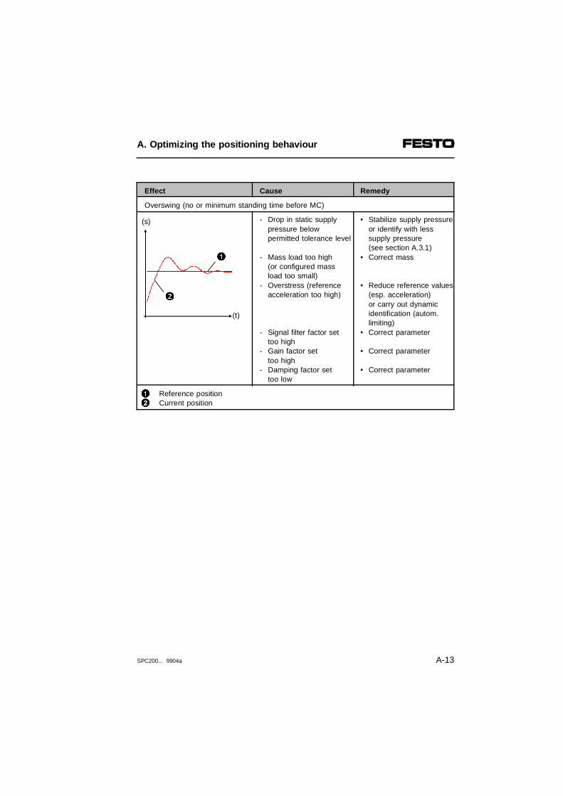
Effect Cause Remedy
Overswing (no or minimum standing time before MC)
- Drop in static supply pressure below permitted tolerance level
- Mass load too high(or configured massload too small)
- Overstress (referenceacceleration too high)
- Signal filter factor settoo high
- Gain factor settoo high
- Damping factor set too low
• Stabilize supply pressureor identify with lesssupply pressure(see section A.3.1)
• Correct mass
• Reduce reference values(esp. acceleration)
or carry out dynamicidentification (autom.limiting)
• Correct parameter
• Correct parameter
• Correct parameter
12
Reference position Current position
(t)
(s)
2
1
A. Optimizing the positioning behaviour
SPC200... 9904a A-13
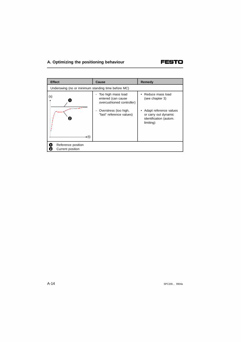
Effect Cause Remedy
Underswing (no or minimum standing time before MC)
- Too high mass loadentered (can cause overcushioned controller)
- Overstress (too high, "fast“ reference values)
• Reduce mass load(see chapter 3)
• Adapt reference values or carry out dynamicidentification (autom.limiting)
12
Reference positionCurrent position
(t)
(s)
2
1
A. Optimizing the positioning behaviour
A-14 SPC200... 9904a

A.3.1 How to deal with an instable compressed air supply
If your compressed air supply does not fulfil the require-ments (tolerance of ± 1 bar in operation), although acompressed air reservoir has already been installed(see section 3.2), the maximum values ascertained foracceleration and slowing down during identification mayunder circumstances not be reached.
This can result, e.g. in overswing, if the operatingpressure required for slowing down cannot be provided.
In order that such overstrain can be avoided, thedynamics of the system must be reduced. Proceedhere as follows:
1. Ascertain the minimum available static supply pressure for positioning in your compressed air system.
2. Lower the supply pressure statically to this level.
3. Now carry out the dynamic identification again.
4. Raise the supply pressure after identification to the value set in the application parameters.
A. Optimizing the positioning behaviour
SPC200... 9904a A-15

A. Optimizing the positioning behaviour
A-16 SPC200... 9904a

Appendix B
Technical appendix
B. Technical appendix
SPC200... 9904a B-1

Contents
B. Technical appendix
B.1 Internal structure of the inputs and outputs ..................................B-3B.2 Technical specifications.................................................................B-7B.2.1 Technical specifications of the SPC200........................................B-7B.2.2 Technical specifications of axis interface type SPC-AIF-... ........B-13B.2.3 Technical specifications of I/O function module
type SPC-FIO-... ..........................................................................B-14B.2.4 Technical specifications of control panel type SPC200-MMI-1...B-15
B. Technical appendix
B-2 SPC200... 9904a

B.1 Internal structure of the inputs and outputs
Internal structure of type SPC200-DIO (PNP inputs)
1
2
Diagnosis (short circuit, overload, protection against incorrect polarity)SPC200, inputs 0...9
34
Logic recognition24 V sensor supply (non floating)
*) Inscription on plug X5/X7 (inputs 0...9)
Fig. B/1: Internal structure of the SPC200-DIO (PNP inputs)
0...9 *)
0 V
1
2
3
4
0 V
24 V +10/-15%
B. Technical appendix
SPC200... 9904a B-3

Internal structure of type SPC200-DIO (PNP outputs)
123
Load voltage connection SPC200, outputs 0...7Electrical isolation
4 Diagnosis (short circuit, overload, loadvoltage failure)
*) Inscription on plug X6/X8 (outputs 0...7)
Fig. B/2: Internal structure of the SPC200-DIO (PNP outputs)
0...7 *)
0 V
1
3
2
4
0 V
+ 24 V
B. Technical appendix
B-4 SPC200... 9904a

Internal structure of type SPC-FIO-2E/2A (PNP inputs)
123
Sensor supply via AIF stringSPC-FIO-... input 1.0 or 1.1Electrical isolation
4
5
Diagnosis (short circuit, overload, protection against incorrect polarity)Green LED
Fig. B/3: Internal structure of the SPC-FIO-2E/2A (PNP inputs)
1
4
2
0 V
+ 24 V
53
Pin 1
Pin 2
Pin 3
B. Technical appendix
SPC200... 9904a B-5
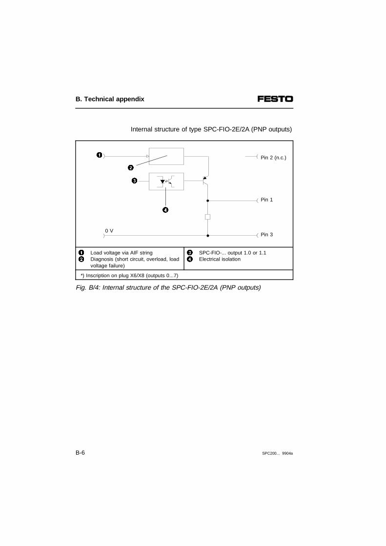
Internal structure of type SPC-FIO-2E/2A (PNP outputs)
12
Load voltage via AIF stringDiagnosis (short circuit, overload, loadvoltage failure)
34
SPC-FIO-... output 1.0 or 1.1Electrical isolation
*) Inscription on plug X6/X8 (outputs 0...7)
Fig. B/4: Internal structure of the SPC-FIO-2E/2A (PNP outputs)
2
0 V
3
4
1 Pin 2 (n.c.)
Pin 1
Pin 3
B. Technical appendix
B-6 SPC200... 9904a

B.2 Technical specifications
B.2.1 Technical specifications of the SPC200
Type SPC200-CPU-...
Dimensions
- height- width- depth
Locations4 6120 mm 120 mm126 mm 166 mm96.5 mm 96.5 mm
Weight- unfitted approx. 675 g approx. 850 g
Temperature range:- operating temperature- storage/transport
- 5 °C ... + 50 °C- 20 °C ... + 70 °C
Relative humidity 95% non condensing
Protection class as per EN 60 529Locations fitted or sealed withblank panels IP 20
NC programming- in accordance with- number of programs - number of NC records- number of NC records per program- position register- nesting depth of subprograms
Program storage without batteryDIN 66025 max. 100max. 2000max. 1000100 per axismax. 4
Oscillation and shock- oscillation - shock
Tested as per DIN/IEC 68 part 2–6severity grade 1Tested as per DIN/IEC 68 part 2–27severity grade 2
Protection against electric shock(protection against direct an indirect contact asper EN 60204-1 / IEC 204
By means of PELV power units (protected extro low voltage)
B. Technical appendix
SPC200... 9904a B-7

Type SPC200-PWR-AIF
Temperature range:- operation- storage/transport
- 5 °C ... + 50 °C-20 °C ... + 70 °C
Weight 82 g
Relative humidity 95% non condensing
Operating voltage pin 1(load voltage supply)- rated value- tolerance 1)
- residual ripple- current consumption
(SPC200-CPU4 and SPC200-CPU-6)
24 V DC-5%...+25% (22.8 V ... 30.0 V) 2%500 mA + 1.2 A per pneumatic axis
Operating voltage pin 2(internal electronics)- rated value- tolerance- residual ripple- power failure bridging time- current consumption at:
SPC200-CPU-4
SPC200-CPU-6
24 V DC-5%...+25% (22.8 V ... 30.0 V)2%10 ms
400 mA + current requirement of components connected to sensor supply 2) + sum of current consumption on AIF string 3)
600 mA + current requirement of components connected to sensor supply 2) + sum of current consumption on AIF string 3)
Electromagnetic compatibility- interference emission
- resistance to interference
Tested as per EN 55011 limit value class A 4) Tested as per EN 50082-2
Oscillation and shock- oscillation - shock
Tested as per DIN/IEC 68 part 2–6severity grade 1Tested as per DIN/IEC 68 part 2–27severity grade 2
1) Observe the tolerance of the modules connected to the axis interface string2) Max. 0.5 A can be made available for each I/O module type SPC200-DIO 3) See technical specifications of the connected modules4) With individual authorization can also be used in residential areas (residential,
business/commercial areas and small firms).
B. Technical appendix
B-8 SPC200... 9904a

Type SPC200-MMI-DIAG
Temperature range:- operation- storage/transport
- 5 oC ... + 50 oC-20 oC ... + 70 oC
Weight 68 g
Relative humidity 95% non condensing
Serial interface (RS232C)- baud rates
- data bits- stop bits- parity- protocol
9600, 19200, 38400, 57600,115200 Baud8 bits1evenNo handshake
Electromagnetic compatibility- interference emission
- resistance to interference
Tested as per EN 55011 limit value class A Tested as per EN 50082-2
Oscillation and shock- oscillation - shock
Tested as per DIN/IEC 68 part 2–6severity grade 1Tested as per DIN/IEC 68 part 2–27severity grade 2
B. Technical appendix
SPC200... 9904a B-9

Type SPC200-DIO (PNP)
Temperature range- operation- storage/transport
- 5 oC ... + 50 oC-20 oC ... + 70 oC
Weight 62 g
Relative humidity 95% non condensing
Digital inputs- design
- logic level; ONOFF
- current consumption (at 24 V)(input current from sensorto input)
- response delay (at 24 V)- reference potential
10 inputs as per IEC 1131-2 type 2inputs 24 V DCpositive switching (PNP)> 11 V< 5 Vat "logic 1"typ. 8 mA
typ. 5 ms0 V
Digital outputs- design- load rating per output- electronic fuse
(short circuit, overload)trigger currentresponse time
8 outputs as per IEC 1131-224 V DC positive switching250 mA
> 2A max. 1.5 ms
Sensor supply VD 24 V ± 25% max. 0.5 A(electronic short circuit protection)
Electrical isolation- inputs- outputs
NoYes
Electromagnetic compatibility- interference emission
- resistance to interference
Tested as per EN 55011limit value class ATested as per EN 50082-2
Oscillation and shock- oscillation - shock
Tested as per DIN/IEC 68 part 2–6severity class 1Tested as per DIN/IEC 68 part 2–27severity class 2
B. Technical appendix
B-10 SPC200... 9904a

Type SPC200-2AI-U
Temperature range- operation- storage/transport
- 5 oC ... + 50 oC-20 oC ... + 70 oC
Weight approx. 55 g
Relative humidity 95% non condensing
Analogue reference value input- input voltage- resolution- input resistance
0...10 V12 bits> 200 kΩ
Electromagnetic compatibility- interference emission
- resistance to interference
Tested as per EN 55011limit value class ATested as per EN 50082-2
Oscillation and shock- oscillation - shock
Tested as per DIN/IEC 68 part 2–6severity class 1Tested as per DIN/IEC 68 part 2–27severity class 2
B. Technical appendix
SPC200... 9904a B-11

Type SPC200-SCU-AIF
Temperature range- operation- storage/transport
- 5 oC ... + 50 oC-20 oC ... + 70 oC
Weight approx. 80 g
Relative humidity 95% non condensing
Current consumption
Electromagnetic compatibility- interference emission
- resistance to interference
Tested as per EN 55011limit value class ATested as per EN 50082-2
Oscillation and shock- oscillation - shock
Tested as per DIN/IEC 68 part 2–6severity class 1Tested as per DIN/IEC 68 part 2–27severity class 2
B. Technical appendix
B-12 SPC200... 9904a
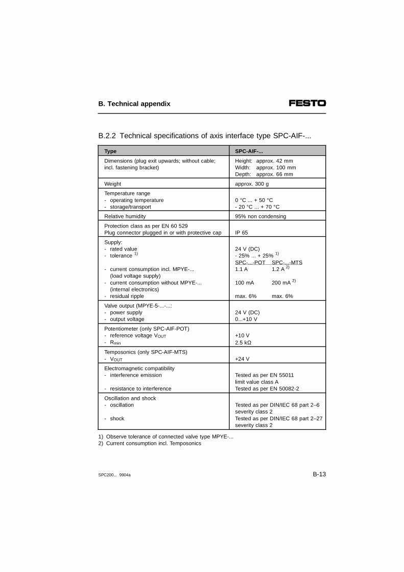
B.2.2 Technical specifications of axis interface type SPC-AIF-...
Type SPC-AIF-...
Dimensions (plug exit upwards; without cable; incl. fastening bracket)
Height: approx. 42 mmWidth: approx. 100 mmDepth: approx. 66 mm
Weight approx. 300 g
Temperature range- operating temperature- storage/transport
0 °C ... + 50 °C- 20 °C ... + 70 °C
Relative humidity 95% non condensing
Protection class as per EN 60 529Plug connector plugged in or with protective cap IP 65
Supply:- rated value- tolerance 1)
- current consumption incl. MPYE-...(load voltage supply)
- current consumption without MPYE-...(internal electronics)
- residual ripple
24 V (DC)- 25% ... + 25% 1) SPC-...-POT SPC-...-MTS1.1 A 1.2 A 2) 100 mA 200 mA 2)
max. 6% max. 6%
Valve output (MPYE-5-...-...:- power supply- output voltage
24 V (DC)0...+10 V
Potentiometer (only SPC-AIF-POT)- reference voltage VOUT
- Rmin
+10 V2.5 kΩ
Temposonics (only SPC-AIF-MTS)- VOUT +24 V
Electromagnetic compatibility- interference emission - resistance to interference
Tested as per EN 55011limit value class ATested as per EN 50082-2
Oscillation and shock- oscillation - shock
Tested as per DIN/IEC 68 part 2–6severity class 2Tested as per DIN/IEC 68 part 2–27severity class 2
1) Observe tolerance of connected valve type MPYE-... 2) Current consumption incl. Temposonics
B. Technical appendix
SPC200... 9904a B-13

B.2.3 Technical specifications of I/O function module type SPC-FIO-...
Type SPC-FIO-2E/2A-M8 1) (PNP)
Temperature range - operation- storage/transport
- 5 oC ... + 50 oC-20 oC ... + 70 oC
Weight 42 g
Relative humidity 95% non condensing
Protective class as per EN 60 529 Plug connector plugged in or with protec-tive cap
IP 65
Electromagnetic compatibility- interference emission
- resistance to interference
Tested as per EN 55011limit value class ATested as per EN 50082-2
Oscillation and shock- oscillation - shock
Tested as per DIN/IEC 68 part 2–6severity class 2Tested as per DIN/IEC 68 part 2–27severity class 2
Digital inputs- design
- protection against incorrect polarity- logic level; ON
OFF- reference potential- current consumption (at 24 V)
(input current from sensor to input)- response delay (at 24 V)
2 inputs as per IEC 1131-2 type 2 inputs24 V DC positive switching PNP, statusdisplay by LED- 30 V ... + 30 V> 11 V < 5 V 0 V
at "logic 1" typ. 7 mAtyp. 3 ms
Sensor supply 2) VD 24 V ± 25% max. 0.5 A (electronic short circuit protection)
Digital outputs- design
- load rating per output 1)
- electronic fuse (short circuit, overload)trigger current
Electrical isolation
2 outputs as per IEC 1131-2; 24 V DCpositive switching250 mA
min. >500 mANone
Internal current consumption of electronics < 40 mA
1) External load voltage supply module type SPC-EXT-PWR is required2) Provided via module SPC200-PWR-AIF (internal electronics, pin 2)
B. Technical appendix
B-14 SPC200... 9904a

B.2.4 Technical specifications of control panel type SPC200-MMI-1
Type SPC200-MMI-1
Dimensions- height- width- depth
approx. 67 mm approx. 59 mm approx. 52 mm
Weight approx. 90 g
Temperature range- operation- storage/transport
- 5 °C ... + 50 °C- 20 °C ... + 70 °C
Relative humidity 95% non condensing
Protection class as per EN 60 529control panel fitted into place IP 20
Oscillation and shock- oscillation - shock
Tested as per DIN/IEC 68 part 2–6severity class 1Tested as per DIN/IEC 68 part 2–27severity 2
B. Technical appendix
SPC200... 9904a B-15

B. Technical appendix
B-16 SPC200... 9904a

Appendix C
Index
C. Index
SPC200... 9904a C-1

C. Index
C-2 SPC200... 9904a

C.1 Index
AAddress range
basic rules . . . . . . . . . . . . . . . . . . . . . . . . . . . . . 3-37SPC200 modules and I/O modules. . . . . . . . . . 1-28
Analogue input modulepin assignment differential inputs . . . . . . . . . . . 3-42
Application parameters . . . . . . . . . . . . . . . . . . . . . . 6-19Autonomous mode. . . . . . . . . . . . . . . . . . . . . . . . . . . 7-6Autonomous operation. . . . . . . . . . . . . . . . . . . . . . . . 7-6Axis designations
assigning the axis designations. . . . . . . . . . . . . 1-17Axis interface
connections . . . . . . . . . . . . . . . . . . . . . . . . . . . . 3-52install . . . . . . . . . . . . . . . . . . . . . . . . . . . . . . . . . 3-51pin assignment of valve connection . . . . . . . . . 3-55
Axis interface stringbasic rules . . . . . . . . . . . . . . . . . . . . . . . . . . . . . 3-48install . . . . . . . . . . . . . . . . . . . . . . . . . . . . . . . . . 3-47structure. . . . . . . . . . . . . . . . . . . . . . . . . . . . . . . 1-17
Axis parameters . . . . . . . . . . . . . . . . . . . . . . . . . . . . 6-18
BBasic unit
mounting . . . . . . . . . . . . . . . . . . . . . . . . . . . . . . . 2-9
CComponents
for setting up a pneumatic axis . . . . . . . . . . . . . 1-14range of equipment for the SPC200 . . . . . . . . . 1-7
Control factors . . . . . . . . . . . . . . . . . . . . . . . . . . . . . 6-51
C. Index
SPC200... 9904a C-3
Control panelfitting. . . . . . . . . . . . . . . . . . . . . . . . . . . . . . . . . . 2-12layout and functions. . . . . . . . . . . . . . . . . . . . . . . 6-4menu structure . . . . . . . . . . . . . . . . . . . . . . . . . . . 6-8test and diagnostic functions . . . . . . . . . . . . . . . 6-53
Coordinated mode . . . . . . . . . . . . . . . . . . . . . . . . . . . 7-5Cylinder diameter . . . . . . . . . . . . . . . . . . . . . . . . . . . 6-18Cylinder length . . . . . . . . . . . . . . . . . . . . . . . . . . . . . 6-18Cylinder type . . . . . . . . . . . . . . . . . . . . . . . . . . . . . . 6-18
DDiagnostic module
pin assignment of MMI socket . . . . . . . . . . . . . . 3-32pin assignment of the serial interface . . . . . . . . 3-31
EEmergency stop circuit
example . . . . . . . . . . . . . . . . . . . . . . . . . . . . . . . 3-17Error
acknowledging a fault . . . . . . . . . . . . . . . . . . . . . 5-8possible problems . . . . . . . . . . . . . . . . . . . . . . . 4-32
Error messages . . . . . . . . . . . . . . . . . . . . . . 8-12 - 8-13structure of error messages. . . . . . . . . . . . . . . . . 8-9
FFitting offset . . . . . . . . . . . . . . . . . . . . . . . . . . . . . . . 6-21Fitting position . . . . . . . . . . . . . . . . . . . . . . . . . . . . . 6-20Function I/O module
connections . . . . . . . . . . . . . . . . . . . . . . . . . . . . 3-57pin assignment of inputs . . . . . . . . . . . . . . . . . . 3-59pin assignment of outputs . . . . . . . . . . . . . . . . . 3-58
C. Index
C-4 SPC200... 9904a
HHalf step. . . . . . . . . . . . . . . . . . . . . . . . . . . . . . . . . . 6-24Hardware configuration
save . . . . . . . . . . . . . . . . . . . . . . . . . . . . . . . . . . 4-16
II/O module
example of circuitry . . . . . . . . . . . . . . . . . . . . . . 3-35pin assignment of inputs (X5/X7) . . . . . . . . . . . 3-34pin assignment of outputs (X6/X8) . . . . . . . . . . 3-35
Identificationdynamic . . . . . . . . . . . . . . . . . . . . . . . . . . . . . . . 4-25static. . . . . . . . . . . . . . . . . . . . . . . . . . . . . . . . . . 4-25
Initial display on the control panel . . . . . . . . . . . . . . . 6-7Installation
measuring system . . . . . . . . . . . . . . . . . . . . . . . 2-19proportional directional control valve. . . . . . . . . 2-19
LLED
on SPC200 . . . . . . . . . . . . . . . . . . . . . . . . . . . . . 8-4Power LED on the axis interface. . . . . . . . . . . . . 8-6Status LED on the function I/O module . . . . . . . 8-7Unlock LED on the axis interface . . . . . . . . . . . . 8-7
Lower software end position . . . . . . . . . . . . . 6-22, 6-24
MMaximum acceleration . . . . . . . . . . . . . . . . . 6-23 - 6-24Maximum speed. . . . . . . . . . . . . . . . . . . . . . 6-23 - 6-24Measuring system
calibrate . . . . . . . . . . . . . . . . . . . . . . . . . . . . . . . 4-29connecting . . . . . . . . . . . . . . . . . . . . . . . . . . . . . 3-54fitting . . . . . . . . . . . . . . . . . . . . . . . . . . . . . . . . . 2-19
C. Index
SPC200... 9904a C-5

Measuring system length . . . . . . . . . . . . . . . . . . . . . 6-18Menu system
menu structure on the control panel . . . . . . . . . . 6-8moving in the menu system. . . . . . . . . . . . . . . . 6-12
Micro step. . . . . . . . . . . . . . . . . . . . . . . . . . . . . . . . . 6-24Mode of reference . . . . . . . . . . . . . . . . . . . . . . . . . . 6-24Modules
install . . . . . . . . . . . . . . . . . . . . . . . . . . . . . . . . . . 2-7remove . . . . . . . . . . . . . . . . . . . . . . . . . . . . . . . . . 2-8
NNC commands
explanation. . . . . . . . . . . . . . . . . . . . . . . . . . . . . 7-13
OOperating mode . . . . . . . . . . . . . . . . . . . . . . . . . . . . 6-26
record selection mode . . . . . . . . . . . 1-22, 5-4, 5-17start/stop mode . . . . . . . . . . . . . . . . . 1-21, 5-4, 5-9
PPictograms . . . . . . . . . . . . . . . . . . . . . . . . . . . . . . . . . VIIIPneumatic axis
components . . . . . . . . . . . . . . . . . . . . . . . . . . . . 1-14instructions on pneumatic installation . . . . . . . . . 3-5summary of pneumatic installation . . . . . . . . . . . 3-5
Position basepoint . . . . . . . . . . . . . . . . . . . . . . . . . . 6-21Positioning tolerance . . . . . . . . . . . . . . . . . . . . . . . . 6-22Power supply module
operating voltage connection. . . . . . . . . 3-25 - 3-26Power supply module and display elements . . . . . . 3-24
C. Index
C-6 SPC200... 9904a

Programadding . . . . . . . . . . . . . . . . . . . . . . . . . . . . . . . . 6-29deleting . . . . . . . . . . . . . . . . . . . . . . . . . . . . . . . 6-42editing . . . . . . . . . . . . . . . . . . . . . . . . . . . . . . . . 6-28parallel program processing . . . . . . . . . . . . . . . . 7-4testing . . . . . . . . . . . . . . . . . . . . . . . . . . . . . . . . 4-34
Programmingediting instructions . . . . . . . . . . . . . . . . . . . . . . 6-35explanation of the NC commands. . . . . . . . . . . 7-13general notes . . . . . . . . . . . . . . . . . . . . . . . . . . . . 7-4instruction set on the control panel . . . . . . . . . . 6-37notes on programming. . . . . . . . . . . . . . . . . . . . . 7-8
Project basepoint . . . . . . . . . . . . . . . . . . . . . . 6-21, 6-24Proportional directional control valve
connecting . . . . . . . . . . . . . . . . . . . . . . . . . . . . . 3-55fitting . . . . . . . . . . . . . . . . . . . . . . . . . . . . . . . . . 2-19
QQuality class. . . . . . . . . . . . . . . . . . . . . . . . . . . . . . . 6-23
RRecord select mode
operating mode . . . . . . . . . . . . . . . . . . . . . . . . . . 5-4summary . . . . . . . . . . . . . . . . . . . . . . . . . . . . . . 5-25
Reference position. . . . . . . . . . . . . . . . . . . . . . . . . . 6-24Reference speed factor . . . . . . . . . . . . . . . . . . . . . . 6-24Resolution . . . . . . . . . . . . . . . . . . . . . . . . . . . . . . . . 6-24
SSetting parameters
summary . . . . . . . . . . . . . . . . . . . . . . . . . . . . . . 6-27Short circuit
sensor supply. . . . . . . . . . . . . . . . . . . . . . . . . . . . 8-8
C. Index
SPC200... 9904a C-7

Slide operation . . . . . . . . . . . . . . . . . . . . . . . . . . . . . 3-19SPC200
address range . . . . . . . . . . . . . . . . . . . . . . . . . . 1-28basic modules . . . . . . . . . . . . . . . . . . . . . . . . . . 1-10extension modules . . . . . . . . . . . . . . . . . . . . . . . 1-11operating modes . . . . . . . . . . . . . . . . . . . . 1-21, 5-3switching-on procedure . . . . . . . . . . . . . . . . . . . . 6-6
Start-stop frequency. . . . . . . . . . . . . . . . . . . . . . . . . 6-24Start/stop
operating mode . . . . . . . . . . . . . . . . . . . . . . . . . . 5-4Start/Stop mode
summary . . . . . . . . . . . . . . . . . . . . . . . . . . . . . . 5-16Supply pressure . . . . . . . . . . . . . . . . . . . . . . . . . . . . 6-20
TTarget group . . . . . . . . . . . . . . . . . . . . . . . . . . . . . . . . VIITechnical specifications
type SPC-AIF-...-.... . . . . . . . . . . . . . . . . . . . . . B-13type SPC-FIO-... . . . . . . . . . . . . . . . . . . . . . . . B-14type SPC200-2AI-U . . . . . . . . . . . . . . . . . . . . . . B-11type SPC200-CPU-.... . . . . . . . . . . . . . . . . . . . . B-7type SPC200-DIO (PNP) . . . . . . . . . . . . . . . . . B-10type SPC200-MMI-1 . . . . . . . . . . . . . . . . . . . . B-15type SPC200-MMI-DIAG . . . . . . . . . . . . . . . . . . B-9type SPC200-PWR-AIF . . . . . . . . . . . . . . . . . . . B-8type SPC200-SCU-AIF . . . . . . . . . . . . . . . . . . B-12
Terms and abbrevations. . . . . . . . . . . . . . . . . . . . . . . . XIText markings . . . . . . . . . . . . . . . . . . . . . . . . . . . . . . . VIIITime behaviour
of I/O signals when processing is started . . . . . . 5-7of the I/O signals in record select mode . . . . . . 5-20programmed stop. . . . . . . . . . . . . . . . . . . . . . . . 5-14when a fault is acknowledged . . . . . . . . . . . . . . . 5-8
Tool load. . . . . . . . . . . . . . . . . . . . . . . . . . . . . . . . . . 6-19
C. Index
C-8 SPC200... 9904a

UUpper software end position . . . . . . . . . . . . . 6-22, 6-24User instructions . . . . . . . . . . . . . . . . . . . . . . . . . . . . VII
VValve type . . . . . . . . . . . . . . . . . . . . . . . . . . . . . . . . 6-18
WWinPISA. . . . . . . . . . . . . . . . . . . . . . . . . . . . . . . . . . 1-26Work load. . . . . . . . . . . . . . . . . . . . . . . . . . . . . . . . . 6-19
YYoke operation . . . . . . . . . . . . . . . . . . . . . . . . . . . . . 3-20
C. Index
SPC200... 9904a C-9

C. Index
C-10 SPC200... 9904a