2016 catalog - olsen chain and cablew-catalog-2016.pdf · design service class and life category...
TRANSCRIPT

• Lifting Beams
• Spreader Beams
• Forklift Attachments
• Material Handling
• Personnel Baskets
• Custom Lifting Devices
www.machiningandwelding.com
Copyright © 2016, Machining & Welding, Cokato, Minnesota
2016 Catalog
D is t r ib u t ed b y :

F A B C
H I B - -H L D ASME B 0 20 ASME BTH-1 OSHA 1 2 251
M B - -H L D D ASME B 0 20 OSHA 1 2 251 D
YES Special custom design grabs, hooks, clamps, or other lifting accessories, for such units as modular panels, prefabricated struc-
tures and similar materials, shall be marked to indicate the safe working loads and be proof-tested prior to use to 125 percent of their rated load.
W ’ ’ B - -H L D D OSHA A ’ ’
H I B - -H L D
H M W B - -H L D
D I B - -H L D
D
H I B - -H L D
se es ons b l t es fo ns e t on a ntenan e an afe e at on fo elo T e oo ft n e es
A M W H I M W
PROOF LOADING1. All elo T e oo ft n e es( T ’s)meetorexceedallASMEB30.20andOSHA1926.251designspeci-
fications,andareproofloadedto125%oftheirstatedWorkingLoadLimit.2. Allchain,wireropeandsyntheticslingsaremanufacturedtomeetandexceedASMEB30.9andOSHA1910.184.
MARKING AND STENCILING OF BTHLD’S1. Stencilmarkingsonbothsideswiththeworkingloadlimit(WLL)andthe a n n el n logo.Anyadditional
marking,whenrequiredbythecustomer,willbenotedonapplicablepaperworkordrawings.2. Stencilmarkingsareblackunlessotherwisespecified.DONOTEXCEEDRATEDCAPACITYwarningdecalisat-
tachedifspacepermits.3. StencilmarkingofWLLis2”letterheightunlessspacedoesnotallow.Maximumletterheightisusedonsmall
spaces.4. TheWLLmarkingislocatedincentrallocationssothatitisbothhighlyvisibleanduprightduringuse.5. AcapacitytagispermanantlyattachedwhichmeetsandexceedsASMEB30.9andOSHAspecifications.6. Allchain,wireropeandsyntheticslingsaretaggedtomeetandexceedASMEB30.9andOSHA1910.184.
DESIGN SERVICE CLASS AND LIFE CATEGORY PER ASME BTH-1-2005Unlessotherwisespecifiedonapplicablepaperworkorproductdrawings,thedesigncategoryusedis“B”andtheservicelifeisClass“0”(upto20,000loadcycles).Differentdesigncategoriesandserviceclassesmustbespecifiedbythebuyerpriortoorderplacement.Theliftingproductwillthenbeengineeredtomeetthespecifiedrequirements.Inspectionre-quiredperASMEB30.20“normalservice.”Fixturestobere-testedanddocumentedannually.
SERVICE TEMPERATURES OF BTHLD’SAllliftdevicesandslingssoldby a n n el n aremanufacturedtomeetorexceedASMEB30.20andASMEB30.9unlessotherwisenoted.Thesespecificationsrequiretheusertoperformapre-liftequipmentinspectionandlimittheamountofimpactandshockloadingtoaminimum.Thisisofextremeimportanceespeciallywhentheservicetemperatureisbelow35˚F,andincreasinglyimportantatlowertemperatures.Onthisbasis,the a n n el n standardservicetemperatureforallBTHLD’siswithinthetemperaturerangeof-40˚Fto150˚F.ThebuyerhastheoptionofpurchasingBTHLD’smadeforarcticserviceto-50˚F.ThesedevicesaremadeofspecialsteelsproducedtowithstandCharpyimpacttestsmadeat-50˚F,andmustbespecifiedbythebuyerpriortoorderplacement.
PRE-LIFT INSPECTION PROCEDURESa n n el n requiresthatbeforeanyliftthattheBTHLDisinspectedforcracks,gougesordeepscratchesin
highstressareasinaccordancewithallapplicableASMEB30.9,ASMEB30.20andOSHArequirements.
REPAIRS OF BTHLD’SAllrepairsofBTHLD’smustbeperformedby a n n el n AnyBTHLDremovedfromuseafterinspectionmustbereturnedto a n n el n forevaluationandinspection.Contact a n n el n forinstructionsandReturnGoodsAuthorization(RGA)numberspriortoreturningBTHLD’sforinspectionorrepair.
WARRANTY OF BTHLD’Sa n n el n warrantseveryitemofitsmanufacture,whenusedundernormaloperatingconditions,tobefree
fromdefectsinmaterialandworkmanship.Ifuponreturnofaproduct,ourexaminationshoulddisclosedefectsinmanu-facture,itisourlimitedobligationunderthiswarrantytomakegoodatourfacilityinCokato,MNthecompleteproductoranyportionthereof,withinthirtydaysfromthedateoforiginalbilling.Ifanyrepairs,heattreatmentorannealingofproductsareconductedatanyplaceotherthanourfacilities,thiswarrantyshallberenderednullandvoid. a n n
el n willassumenootherobligationsorliabilities,expressedorimplied,thanthosecontainedinthiswarranty.Thiswarranty,whichisgivenexpresslyandinlieuofallotherwarranties,expressedorimplied,ofmerchantabilityandfitnessforaparticularpurpose,constitutestheonlywarrantymadeby a n n el n
a n n el n reservestherighttomodifyinformationandengineeringspecificationsinthispublicationwithoutnotice.Allproductssoldby a n n el n aresoldwiththeexpressunderstandingthatthepurchaseristhor-oughlyfamiliarwiththesafeandproperuseandapplicationoftheproduct.Responsibilityfortheuseandapplicationoftheproductsrestswiththeuser.Therearenumerousgovernmentandindustrystandardsthatcoverproductsmadeby
a n n el n Thiscatalogmakesnoattempttoreferenceallofthem.Wedoreferencethestandardsthatwearemostfrequentlyaskedabout.WorkingLoadLimit(WLL)ratingsindicatethegreatestforceorloadaproductcancarryunderusualenvironmentalconditions.ShockloadingandextraordinaryconditionsmustbetakenintoaccountbytheuserwhenselectingBTHLD’sasproductsforuseinaliftingsystem.Productfailurecouldallowtheloadtobecomeoutofcontrol,resultinginpossiblepropertydamage,personalinjuryordeath.t
PROOF LOADING1. All BTHLDs meet or exceed all ASME B30.20 and OSHA 1926.251 design specifications, and are proof loaded to
125% of their stated Working Load Limit.2. All chain, wire rope and synthetic slings are manufactured to meet and exceed ASME B30.9 and OSHA 1910.184.
MARKING AND STENCILING OF BTHLDs1. Stencil markings on both sides with the working load limit (WLL) and the Machining & Welding logo. Any additional
marking, when required by the customer, will be noted on applicable paperwork or drawings.2. Stencil markings are black unless otherwise specified. DO NOT EXCEED RATED CAPACITY. Warning decal is at-
tached if space permits.3. Stencil marking of WLL is 2” letter height unless space does not allow. Maximum letter height is used on small
spaces.4. The WLL marking is located in central locations so that it is both highly visible and upright during normal use.5. A capacity tag is permanantly attached which meets and exceeds ASME B30.9 and OSHA specifications.6. All chain, wire rope, and synthetic slings are tagged to meet and exceed ASME B30.9 and OSHA 1910.184.
DESIGN SERVICE CLASS AND LIFE CATEGORY PER ASME BTH-1Unless otherwise specified on applicable paperwork or product drawings, the design category used is “B” and the service life is Class “2” (up to 500,000 load cycles). Different design categories and service classes must be specified by the buyer prior to order placement. The lifting product will then be engineered to meet the specified requirements. Inspection required per ASME B30.20 “normal service.” Fixtures to be re-tested and documented annually.
SERVICE TEMPERATURES OF BTHLD’SAll lifting devices and slings sold by Machining & Welding are manufactured to meet or exceed ASME B30.20 and ASME B30.9 unless otherwise noted. These specifications require the user to perform a pre-lift equipment inspection and limit the amount of impact and shock loading to a minimum. This is of extreme importance especially when the service temperature is below 35˚F, and increasingly important at lower temperatures. On this basis, the Machining & Welding standard service temperature for all BTHLDs is within the temperature range of -40˚F to 150˚F. The buyer has the option of purchasing BTHLDs made for arctic service to -50˚F. These devices are made of special steels produced to withstand Charpy impact tests made at -50˚F, and must be specified by the buyer prior to order placement.
PRE-LIFT INSPECTION PROCEDURESMachining & Welding requires that before any lift, the BTHLD is inspected for cracks, gouges, or deep scratches in high stress areas in accordance with all applicable ASME B30.9, ASME B30.20 and OSHA requirements.
REPAIRS OF BTHLDsAll repairs of BTHLDs must be performed by Machining & Welding. Any BTHLD removed from use after inspection must be returned to Machining & Welding for evaluation and inspection. Contact Machining & Welding for instructions and Return Goods Authorization (RGA) numbers prior to returning BTHLDs for inspection or repair.
WARRANTY OF BTHLDsMachining & Welding warrants every item of its manufacture, when used under normal operating conditions, to be free from defects in material and workmanship. If upon return of a product, our examination should disclose defects in manu-facture, it is our limited obligation under this warranty to make good at our facility in Cokato, MN, the complete product or any portion thereof, within thirty days from the date of original billing. If any repairs, heat treatment, or annealing of products are conducted at any place other than our facilities, this warranty shall be rendered null and void. Machining & Welding will assume no other obligations or liabilities, expressed or implied, than those contained in this warranty. This warranty, which is given expressly and in lieu of all other warranties, expressed or implied, of merchantability and fitness for a particular purpose, constitutes the only warranty made by Machining & Welding.

Machining & Weldingwww.MachiningAndWelding.com
Table of Contents
LIFTING BEAMSAdjustable Length Lifting Beams ......................Low Headroom, Multiple Length Standard Lifting Beams .........................................Non-Conductive Lifting Beam .............................Basket Lifting Beam ..............................................Economy H-Beam .................................................Bottle Lifting Beam ...............................................Ultra Low Headroom Lifting Beams ..................Twin Hoist Lifting Beams ....................................Roll Lifting Beams ................................................Adjustable Economy Lifting Beams ...................Plate Lifting Beams ..............................................Economy (Fixed Length) Lifting Beams ............Barrel / Bucket Lifter ............................................Bulk Container Lift Beam ....................................Material Stands: Heavy-Duty, Load Tested .......Coil Lifters / Upenders .........................................Small Length Lift Beams ......................................
INDEXING LIFTING DEVICESBarrier Lifters .......................................................Beam Lifters ..........................................................Padded Pipe Lifting Clamps..................................
SPREADER BEAMSLarge Capacity Spreader Beams .........................Fixed and Adjustable Spread ...............................End Cap Spreader Beam Kits...............................
FORKLIFT ATTACHMENTSForklift Lifting Beams ..........................................Forklift Adjustable Reach Over Boom ...............Forklift Pocket Lifters ..........................................
Page 1 -2
Page 3 - 4Page 5Page 6Page 7Page 8Page 9Page 10Page 11 - 12Page 13Page 14Page 15Page 16Page 17Page 18Page 19 - 20Page 21 - 22
Page 31 - 33Page 34Page 35
Page 26Page 27 - 28Page 29 - 30
MATERIAL BASKETSDrop Side and Fixed Sides ..................................
PERSONNEL BASKETSPersonnel Baskets with optional Test Weightand Suspension Rigging .......................................
HOOKS - LIFTINGAlloy Steel J-Hooks Style 9 ....................................................... Style A ...................................................... Style B ...................................................... Style C ......................................................Alloy Steel Sorting Hooks ....................................Custom Paintline Hooks ......................................Alloy Steel Latching J-Hooks ..............................Alloy Steel Foundry Hooks ..................................Alloy Steel Stirrup / Double Hooks .....................Alloy Steel Flat Hooks ..........................................Alloy Steel S-Hooks ..............................................Sling Inspection and Measuring Hook ...............
WIRE ROPE TERMINATIONS ............
SAFETY INSTRUCTIONSManufacturing and Testing Specifications ........
Page 69Page 70Page 71Page 72Page 73Page 74Page 75Page 76Page 77Page 78 - 79Page 80Page 82 - 83
Page 84 - 87
Page 81, 88
Page 62 - 64
Page 65 - 68
MATERIAL HANDLINGPallet Lifters ..........................................................Forklift Personnel Basket .....................................Pipe Lifting Hooks ................................................Grade 100 Plate Lifting Hooks ............................Synthetic Lifting Sling Triangle and Choker Fittings ................Wire Mesh Sling Triangle and Choker Fittings ................Alloy Chain Mesh Sling Triangle and Choker Fittings ................Container Lifting Lugs .........................................Insulated Swivel Hooks .........................................Hydrant Lifter .......................................................Trailer Spotter .......................................................Beam Clamps ........................................................Bar Tong Lifter .....................................................Reel Lifting / Turning ...........................................Concrete Pipe / Manhole Lifting Equipment .....Clamp On Bucket Forks ......................................Manhole Sleeve Lifter ...........................................
Page 36 - 39Page 40Page 41Page 42
Page 43 - 44
Page 45
Page 46Page 47Page 48Page 49Page 50Page 51 - 52Page 53Page 54 - 56Page 57 - 59Page 60Page 61
Page 23Page 24Page 25

Machining & Weldingwww.MachiningAndWelding.com
Adjustable Length Lifting Beams with Swivel Hook bottoms
ft n ea sstable en t ft n ea s
t el oo botto s
ManufacturedtoexceedallASMEB30.20andOSHAregulations.
Paintedsafetyyellowforincreasedvisibility. LiftingBeamsproofloadedandshippedwith
certificationpaperwork. Durableconstructionideallysuitedtojobsiteorware-
houseuse.
Working Load Limitin Pounds*
PartNumber L min L max A B C D HR Weight
in Pounds
2,000 16410 48 72 3 5 0.75 0.63 13.8 852,000 16411 120 144 3 5 0.75 0.63 15.7 2854,000 16412 48 72 3 5 1.5 0.63 14.6 1354,000 16413 120 144 3 5 1.5 0.63 16.6 3306,000 16414 48 72 3 5 1.5 0.63 16.2 1606,000 16415 120 144 3 5 1.5 0.63 19.1 5308,000 16416 48 72 4 7 2 0.75 18.9 2008,000 16417 120 144 4 7 2 0.75 20.9 540
10,000 16418 48 72 4 7 2 0.75 21.2 30010,000 16419 120 144 4 7 2 0.75 22.2 79515,000 16420 48 72 4 7 2 1.00 22.1 31515,000 16421 120 144 4 7 2 1.00 25.1 815
* Call for specifications on larger sizes and capacities
MadeinU.S.A. Customletteringavailable-callfordetails. Customdesignsavailable-callforengineering. liftingequipmentindividuallyproofloadedper
OSHArequirements. Alldimensionsininchesunlessotherwisenoted.
uickandeasyadjustmentofunbalancedloads. Ideallysuitedtolowheadroomapplications. Picturedwithstandardalloyswivellatchhooks. Eyehooksandcustomconnectionsavailable-callfororderingassistance.
RFID TRACKING
CHIP EQUIPPED
LIF
TIN
G B
EA
MS
1

Machining & Weldingwww.MachiningAndWelding.com
Adjustable Length Lifting Beams with Shackle bottoms ManufacturedtoexceedallASMEB30.20andOSHA
regulations. Paintedsafetyyellowforincreasedvisibility. LiftingBeamsproofloadedandshippedwith
certificationpaperwork. Durableconstructionideallysuitedtojobsiteorware-
houseuse.
Working Load Limitin Pounds*
PartNumber L min L max A B C D HR Weight
in Pounds
2,000 15101 36 72 3 5 0.75 0.63 11.8 852,000 14678 72 144 3 5 0.75 0.63 13.8 2854,000 12453 36 72 3 5 1.5 0.63 12.6 1354,000 12495 72 144 3 5 1.5 0.63 14.6 3316,000 14669 36 72 3 5 1.5 0.63 14.8 1706,000 14661 72 144 3 5 1.5 0.63 17.8 5358,000 12503 36 72 4 7 2 0.75 18.0 2018,000 12512 72 144 4 7 2 0.75 20.0 543
10,000 14651 36 72 4 7 2 0.75 20.0 31010,000 15108 72 144 4 7 2 0.75 21.0 80515,000 15117 36 72 4 7 2 1.00 20.7 32515,000 15128 72 144 4 7 2 1.00 23.7 830
* Call for specifications on larger sizes and capacities
MadeinU.S.A. Customletteringavailable-callfordetails. Customdesignsavailable-callforengineering. liftingequipmentindividuallyproofloadedper
OSHArequirements. Alldimensionsininchesunlessotherwisenoted.
uickandeasyadjustmentofunbalancedloads. Ideallysuitedtolowheadroomapplications. Shacklebottomsstandardforriggingconnections. Swivelhooks,eyehooksandcustomconnectionsavailable-callfororderingassistance.
ft n ea sstable en t ft n ea s
t a le botto s
RFID TRACKING
CHIP EQUIPPED
RFID TRACKING
CHIP EQUIPPED
LIF
TIN
G B
EA
MS
2

Machining & Weldingwww.MachiningAndWelding.com
Low Headroom, Multiple Length Standard Lifting Beam ManufacturedtoexceedallASMEB30.20andOSHA
regulations. Paintedsafetyyellowforincreasedvisibility. LiftingBeamsproofloadedandshippedwith
certificationpaperwork. Durableconstructionideallysuitedtojobsiteorware-
houseuse.
MadeinU.S.A. Machinedtoexactingtolerances. Customletteringavailable-callfordetails. Customdesignsavailable-callforengineering. liftingequipmentindividuallyproofloadedper
OSHArequirements.
WorkingLoad Limit in
Pounds
odel NumberHeadroom inWeight lbs
utside Length L in Feet
4 6 8 10 12
1,000Part Number
HR LB
1193713.11
56
1195913.11
75
1196013.11
95
1196113.11115
1196213.11200
2,000Part Number
HR LB
1198313.11
56
1198413.11
75
1198514.11167
1198914.11205
1199014.11240
4,000Part Number
HR LB
1203215.12
98
1203315.12135
1203416.12200
1203916.12295
1204217.12395
6,000Part Number
HR LB
1206915.25120
1208416.25180
1208717.25255
1209018.25380
1209418.25440
10,000Part Number
HR LB
1211721.25265
1212321.25345
1212621.25430
1212922.25500
1213221.12590
15,000Part Number
HR LB
1216224.27265
1216524.28365
1216825.28450
1217125.28640
1217425.28870
20,000Part Number
HR LB
1219923.75290
1220224.75375
1220524.75625
1220826.75755
1221229.75985
30,000Part Number
HR LB
1222329.00345
1222929.00555
1223234.00675
1223634.001,235
1226340.201,185
40,000Part Number
HR LB
1225033.81445
1225433.81850
1225733.811,050
1228741.791,195
1229241.971,540
Picturedwithstandardalloyswivellatchhooks. Ideallysuitedforlowheadroomliftingapplications. Multiplelatchhooks,eyelatchhooksandshackleplatesavailable.Pleasecallforordering
assistance.
ft n ea so ea oo lt le en ttan a ft n ea
LIF
TIN
G B
EA
MS
3

Machining & Weldingwww.MachiningAndWelding.com
RFID TRACKING
CHIP EQUIPPED
utside Length L in Feetther
Dimensions
WorkingLoad Limit in
Pounds14 16 18 20 24
1196813.11226
1197114.11313
1197414.11350
1197714.11390
1198115.11535
C .875, A 3.0B 5.0, D .75
E .911,000
1201715.11320
1201815.11365
1201915.11500
1202016.11525
1202417.11945
C .875, A 3.0B 5.0, D .75
E .912,000
1204618.12575
1205018.12650
1205519.12771
1205920.121,060
1206322.121,510
C .875, A 3.0B 5.0, D .75
E 1.04,000
1209819.25635
1210219.25715
1210620.25990
1210920.251,295
1211222.251,310
C 1.25, A 3.0B 5.0, D 1.00
E 1.006,000
1213822.25970
1214122.251,095
1214824.251,035
1215224.251,340
1215526.501,800
C 2.0, A 4.0B 7.0, D 1.25
E 1.0910,000
1217727.281,000
1218030.281,265
1218330.281,405
1218629.841,800
C 2.0, A 4.0B 7.0, D 1.25
E 1.5615,000
1221529.751,595
1221829.751,799
1228035.081,655
1228435.081,815
C 2.0, A 4.0B 7.0, D 1.25
E 1.6120,000
1226740.481,540
1227040.661,865
1227440.842,250
1227741.072,750
C 2.5, A 5.0B 9.0, D 1.50
E 2.0830,000
1229542.151,850
1230043.582,130
1230443.742,555
1230743.923,045
C 2.5, A 5.0B 9.0, D 1.50
E 2.0840,000
ft n ea so ea oo lt le en t
tan a ft n ea
LIF
TIN
G B
EA
MS
4

Machining & Weldingwww.MachiningAndWelding.com
Non-Conductive Lifting Beam
ft n ea son Con t e ft n ea
ManufacturedtoexceedallASMEB30.20andOSHAregulations.
Paintedsafetyyellowliftlugforincreasedvisibility. LiftingBeamsproofloadedandshippedwith
certificationpaperwork. Durableconstructionideallysuitedtojobsiteorware-
houseuse.
MadeinU.S.A. Customletteringavailable-callfordetails. Customdesignsavailable-callforengineering. liftingequipmentindividuallyproofloadedper
OSHArequirements. Alldimensionsininchesunlessotherwisenoted.
uickandeasyadjustmentofunbalancedloads. Ideallysuitedtohandlelargebatteries Naturalsparkproofinsulation OptionalHooksandLugconnectionsavailable-callfororderingassistance
RFID TRACKING
CHIP EQUIPPED
Working Load Limitin Pounds*
PartNumber A B C D HR L min L max
2,000 17441 3.8 3.0 1.0 0.63 10.15 18.0 30.02,000 17442 3.8 3.0 1.0 0.63 10.15 30.0 42.04,000 17443 3.8 3.0 1.0 0.63 12.20 18.0 30.04,000 17171 3.8 3.0 1.0 0.63 12.20 30.0 42.0
* Call for specifications on larger sizes and capacities
5
LIF
TIN
G B
EA
MS
Machining & Weldingwww.MachiningAndWelding.com
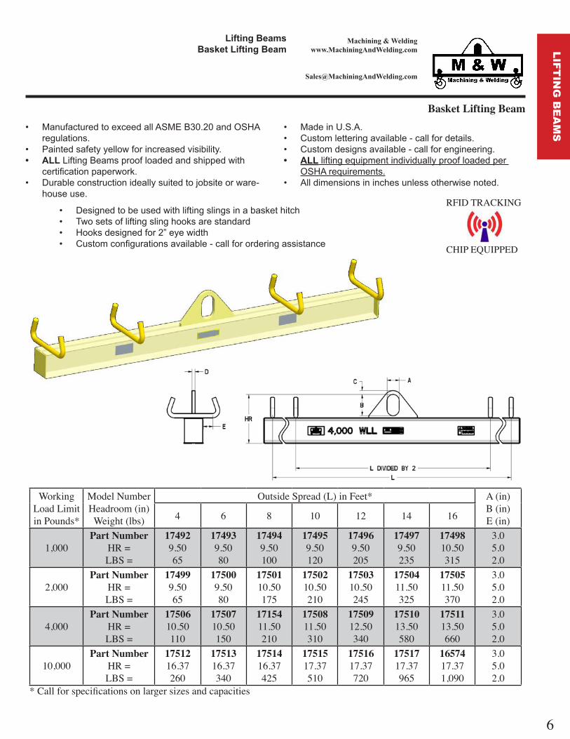
Basket Lifting Beam ManufacturedtoexceedallASMEB30.20andOSHA
regulations. Paintedsafetyyellowforincreasedvisibility. LiftingBeamsproofloadedandshippedwith
certificationpaperwork. Durableconstructionideallysuitedtojobsiteorware-
houseuse.
MadeinU.S.A. Customletteringavailable-callfordetails. Customdesignsavailable-callforengineering. liftingequipmentindividuallyproofloadedper
OSHArequirements. Alldimensionsininchesunlessotherwisenoted.
Designedtobeusedwithliftingslingsinabaskethitch Twosetsofliftingslinghooksarestandard Hooksdesignedfor2”eyewidth Customconfigurationsavailable-callfororderingassistance
ft n ea sas et ft n ea
RFID TRACKING
CHIP EQUIPPED
Working Load Limit in Pounds*
odel NumberHeadroom inWeight lbs
utside pread L in Feet* A inB inE in4 6 8 10 12 14 16
1,000Part Number
HR LB
174929.5065
174939.5080
174949.50100
174959.50120
174969.50205
174979.50235
1749810.50315
3.05.02.0
2,000Part Number
HR LB
174999.5065
175009.5080
1750110.50175
1750210.50210
1750310.50245
1750411.50325
1750511.50370
3.05.02.0
4,000Part Number
HR LB
1750610.50110
1750710.50150
1715411.50210
1750811.50310
1750912.50340
1751013.50580
1751113.50660
3.05.02.0
10,000Part Number
HR LB
1751216.37260
1751316.37340
1751416.37425
1751517.37510
1751617.37720
1751717.37965
1657417.371,090
3.05.02.0
* Call for specifications on larger sizes and capacities
6
LIF
TIN
G B
EA
MS

Machining & Weldingwww.MachiningAndWelding.com
Economy H-Beam
ft n ea sono ea
ManufacturedtoexceedallASMEB30.20andOSHAregulations.
Paintedsafetyyellowforincreasedvisibility. LiftingBeamsproofloadedandshippedwith
certificationpaperwork. Durableconstructionideallysuitedtojobsiteorware-
houseuse.
MadeinU.S.A. Customletteringavailable-callfordetails. Customdesignsavailable-callforengineering. liftingequipmentindividuallyproofloadedper
OSHArequirements. Alldimensionsininchesunlessotherwisenoted.
uickandeasyadjustmentofunbalancedloads. Ideallysuitedtolowheadroomapplications. Eyehooksandcustomconnectionsavailable-callfororderingassistance.
RFID TRACKING
CHIP EQUIPPEDWorking
Load Limit in Pounds*
odel NumberHeadroom inWeight lbs
utside pread L in Feet*
4 6 8 10
1,00048 Width
Part NumberHR LB
1756015.1135
1756315.1150
1756616.1185
2,00048 Width
Part NumberHR LB
1756916.1150
1757217.1180
1757517.1250
4,00048 Width
Part NumberHR LB
1757818.1185
1758219.1245
1758620.1360
1759020.1415
8,00048 Width
Part NumberHR LB
1759825.6305
1760225.6410
1760625.6565
* Call for specifications on larger sizes and capacities
Working Load Limit in Pounds*
odel NumberHeadroom inWeight lbs
utside pread L in Feet*
4 6 8 10
1,00096 Width
Part NumberHR LB
1756215.1195
1756515.1210
1756816.1245
2,00096 Width
Part NumberHR LB
1757117.1240
1757417.1270
1757718.1340
4,00096 Width
Part NumberHR LB
1758019.1365
1758419.1425
1758820.1540
1759220.1595
8,00096 Width
Part NumberHR LB
1760027.6655
1760427.6760
1760827.6915
* Call for specifications on larger sizes and capacities
Working Load Limit in Pounds*
odel NumberHeadroom inWeight lbs
utside pread L in Feet*
4 6 8 10
1,00072 Width
Part NumberHR LB
1756115.1165
1756415.1180
1756716.1215
2,00072 Width
Part NumberHR LB
1757017.1170
1757317.1200
1757618.1340
4,00072 Width
Part NumberHR LB
1757919.1255
1758319.1285
1758721.1400
1759121.1455
8,00072 Width
Part NumberHR LB
1759926.6425
1760326.6530
1760726.6685
* Call for specifications on larger sizes and capacities
Working Load Limit in Pounds*
odel NumberHeadroom inWeight lbs
utside pread L in Feet*
4 6 8 10
4,000120
Width
Part NumberHR LB
1758119.1425
1758519.1485
1758921.1600
1759321.1655
8,000120
Width
Part NumberHR LB
1760127.6765
1760527.6870
1760927.6
1,025* Call for specifications on larger sizes and capacities
7
LIF
TIN
G B
EA
MS

Machining & Weldingwww.MachiningAndWelding.com
Bottle Lifting Device ManufacturedtoexceedallASMEB30.20andOSHA
regulations. Paintedsafetyyellowforincreasedvisibility. BottleLiftersproofloadedandshippedwith
certificationpaperwork. Durableconstructionideallysuitedtojobsiteorware-
houseuse.
MadeinU.S.A. Customletteringavailable-callfordetails. Customdesignsavailable-callforengineering. liftingequipmentindividuallyproofloadedper
OSHArequirements. Alldimensionsininchesunlessotherwisenoted.
Adjustablestrapstoholdtanks Lockabledoors
ft n ea sottle ft n e e
RFID TRACKING
CHIP EQUIPPED
Working Load Limitin Pounds*
PartNumber
TankCapacit Weight
750 16307 2 3001,500 17324 4 525500 20199 1 150
* Call for specifications on larger sizes and capacities
8
LIF
TIN
G B
EA
MS

Machining & Weldingwww.MachiningAndWelding.com
Ultra Low Headroom Lifting Beams ManufacturedtoexceedallASMEB30.20andOSHA
regulations. Paintedsafetyyellowforincreasedvisibility. LiftingBeamsproofloadedandshippedwith
certificationpaperwork. Durableconstructionideallysuitedtojobsiteorware-
houseuse. Useprovidedspacerstoassurehookremainscentered.
WorkingLoad Limitin Pounds*
Part numberHeadroom
Weight
pread in Feet LA B D
4 6 8 10 12
1,000Part number
CE
Weight
164845.5
1.9457
164855.51.9482
164865.51.94100
164875.51.94120
164885.51.94145
2.25 0.63 0.86
2,000Part number
CE
Weight
164895.5
2.0060
164905.52.0085
164916.52.00175
164926.52.00215
164936.52.00250
2.25 0.75 0.86
4,000Part number
CE
Weight
164946.7
2.13110
164956.72.13150
164967.12.75210
164977.12.75310
164987.93.00345
2.25 1.00 0.89
6,000Part number
CE
Weight
164996.9
2.51125
165007.62.76185
165018.62.76255
165029.62.76300
165039.62.76400
3.00 1.25 0.96
10,000Part number
CE
Weight
165049.8
3.25240
165059.83.25320
165069.83.25400
1650710.33.75490
1650810.33.75695
3.00 1.50 1.08
* Call for specifications on larger sizes and capacities
MadeinU.S.A. Customletteringavailable-callfordetails. Customdesignsavailable-callforengineering. liftingequipmentindividuallyproofloadedper
OSHArequirements. Beamssuppliedstandardwithalloyswivellatchhook
connections.
RFID TRACKING
CHIP EQUIPPED
ft n ea slt a o ea oo ft n ea s
9
LIF
TIN
G B
EA
MS

Machining & Weldingwww.MachiningAndWelding.com
Twin Hoist Lifting Beams ManufacturedtoexceedallASMEB30.20andOSHA
regulations. Paintedsafetyyellowforincreasedvisibility. LiftingBeamsproofloadedandshippedwith
certificationpaperwork. Durableconstructionideallysuitedtojobsiteorware-
houseuse.
MadeinU.S.A. Customletteringavailable-callfordetails. Customdesignsavailable-callforengineering. liftingequipmentindividuallyproofloadedper
OSHArequirements. Alldimensionsininchesunlessotherwisenoted.
uickandeasyliftingofloadswithtwohoists.Liftingmustbedonewithin5 ofvertical. Ideallysuitedtolowheadroomapplications. Alloyswivelhookbottomstandardconnection. Load-bearingswivelhook,eyehook,andcustomconnectionsavailable-callfor
orderingassistance.
ft n ea sT n o st ft n ea s
RFID TRACKING
CHIP EQUIPPED
WorkingLoad Limitin Pounds*
Part numberHeadroom
Weight
pread in Feet LA B C D E
6 8 10 12 14 16 18 20
4,000Part number
HRWeight
1642715.10140
1642816.10191
1642916.10260
1643017.10320
1643118.10560
1643218.10640
1643319.10765
1643420.101,055
3.0 5.0 0.88 0.63 0.96
6,000Part number
HRWeight
1643516.50150
1643617.50225
1643718.50265
1643818.50485
1643919.50600
1644019.50690
1644120.50960
1644220.501,260
3.0 5.0 1.00 0.63 1.08
10,000Part number
HRWeight
1644322.31300
1644422.31380
1644522.31470
1644623.31670
1644723.31920
1644823.311,040
1644925.311,005
1645025.311,305
3.0 5.0 1.00 0.75 1.56
15,000Part number
HRWeight
1645125.75310
1645226.75395
1645326.75580
1645426.75810
1645528.75950
1645631.751,215
1645731.751,575
1645831.751,740
4.0 7.0 1.00 0.75 2.17
20,000Part number
HRWeight
1645927.53370
1646027.53585
1646129.53725
1646232.53975
1646332.531,565
1646432.531,770
4.0 7.0 1.25 1.00 2.28
* Call for specifications on larger sizes and capacities
10
LIF
TIN
G B
EA
MS

Machining & Weldingwww.MachiningAndWelding.com
Roll Lifting Beams ManufacturedtoexceedallASMEB30.20andOSHA
regulations. Paintedsafetyyellowforincreasedvisibility. LiftingBeamsproofloadedandshippedwith
certificationpaperwork. Durableconstructionideallysuitedtojobsiteorware-
houseuse. Useprovidedspacerstoassurehookremainscentered.
MadeinU.S.A. Customletteringavailable-callfordetails. Customdesignsavailable-callforengineering. liftingequipmentindividuallyproofloadedper
OSHArequirements. Beamssuppliedstandardwithalloyswivellatchhook
connections.
ft n ea soll ft n ea s
Working Load Limit
Part Number
ax RollDiameter
ax Arbor
Diameter
Inside Length Weight
2,000 20715 36 3 50 752,000 20716 36 3 74 1054,000 20717 36 3 50 1154,000 20718 36 3 74 154
* Call for specifications on larger sizes and capacities
Working Load Limit
Part Number
ax RollDiameter
ax Arbor
Diameter
Inside Length Weight
6,000 20721 36 3 50 2006,000 20722 36 3 74 245
10,000 20719 36 3 50 37010,000 20720 36 3 74 450
* Call for specifications on larger sizes and capacities
Working Load Limit
Part Number
ax RollDiameter
ax Arbor
Diameter
Inside Length Weight
6,000 20756 36 3 50 2056,000 20755 36 3 74 255
10,000 20754 36 3 50 36010,000 20753 36 3 74 440
* Call for specifications on larger sizes and capacities
11
LIF
TIN
G B
EA
MS

Machining & Weldingwww.MachiningAndWelding.com
Adjustable Roll Lifting Beams ManufacturedtoexceedallASMEB30.20andOSHA
regulations. Paintedsafetyyellowforincreasedvisibility. LiftingBeamsproofloadedandshippedwith
certificationpaperwork. Durableconstructionideallysuitedtojobsiteorware-
houseuse.
MadeinU.S.A. Customletteringavailable-callfordetails. Customdesignsavailable-callforengineering. liftingequipmentindividuallyproofloadedper
OSHArequirements. Alldimensionsininchesunlessotherwisenoted.
uickandeasyliftingliftingandpositioningofrolls. Ideallysuitedtolowheadroomapplications. Customhooklengthsavailable-callforquote.
ft n ea sstable oll ft n ea s
RFID TRACKING
CHIP EQUIPPED
Working Load Limit
Part Number
ax RollDiameter
ax Arbor
Diameter
Inside Length Weight
2,000 20784 36 3 22 76 130* Call for specifications on larger sizes and capacities
Working Load Limit
Part Number
ax RollDiameter
ax Arbor
Diameter
Inside Length Weight
6,000 20785 36 3 22 76 20010,000 20786 36 3 22 76 520
* Call for specifications on larger sizes and capacities
12
LIF
TIN
G B
EA
MS

Machining & Weldingwww.MachiningAndWelding.com
Adjustable Economy Lifting Beams ManufacturedtoexceedallASMEB30.20andOSHA
regulations. Paintedsafetyyellowforincreasedvisibility. LiftingBeamsproofloadedandshippedwith
certificationpaperwork. Durableconstructionideallysuitedtojobsiteorware-
houseuse.
MadeinU.S.A. Customletteringavailable-callfordetails. Customdesignsavailable-callforengineering. liftingequipmentindividuallyproofloadedper
OSHArequirements. Beamssuppliedstandardwithshackleconnections.
RFID TRACKING
CHIP EQUIPPED
uickandeasyadjustmentofunbalancedloads. Ideallysuitedtolowheadroomapplications. Shacklebottomsstandardforriggingconnections. Swivelhooks,eyehooksandcustomconnectionsavailable-callfororderingassistance.
ft n ea sstable ono ft n ea s
Working Load Limitin Pounds*
PartNumber
axpread
inpread
BailAd HR Weight
in PoundsTop hackle Part Number
Bottom hackle Part Number
500 13855 48 12 16 7.57 45 1019470 1019470500 13862 72 36 16 7.57 60 1019470 1019470500 13866 96 60 16 7.57 75 1019470 1019470
1,000 13878 48 12 16 7.57 45 1019470 10194701,000 13879 72 36 16 7.57 60 1019470 10194701,000 13869 96 60 24 8.57 95 1019470 10194702,000 13880 48 12 16 8.57 60 1019470 10194702,000 13886 72 36 24 9.57 80 1019470 10194702,000 13889 96 60 24 9.57 150 1019470 10194702,000 13893 120 84 24 9.57 180 1019470 10194704,000 13924 48 12 16 9.48 65 1019472 10194714,000 13933 72 36 24 10.48 125 1019472 10194714,000 13938 96 60 24 11.48 240 1019472 10194714,000 14130 120 84 24 11.48 295 1019472 10194718,000 14134 72 24 32 15.12 175 1019515 10194908,000 14150 96 48 32 16.12 280 1019515 10194908,000 14154 120 72 32 16.12 435 1019515 101949010,000 14159 96 36 32 16.12 365 1019515 101949010,000 14162 120 60 32 17.12 465 1019515 101949010,000 14167 144 84 32 18.12 675 1019515 101949014,000 14171 120 48 32 19.42 610 1019533 101951514,000 14177 144 72 32 21.42 715 1019533 101951514,000 14182 168 96 32 21.42 965 1019533 1019515
* Call for specifications on larger sizes and capacities13
LIF
TIN
G B
EA
MS
Machining & Weldingwww.MachiningAndWelding.com
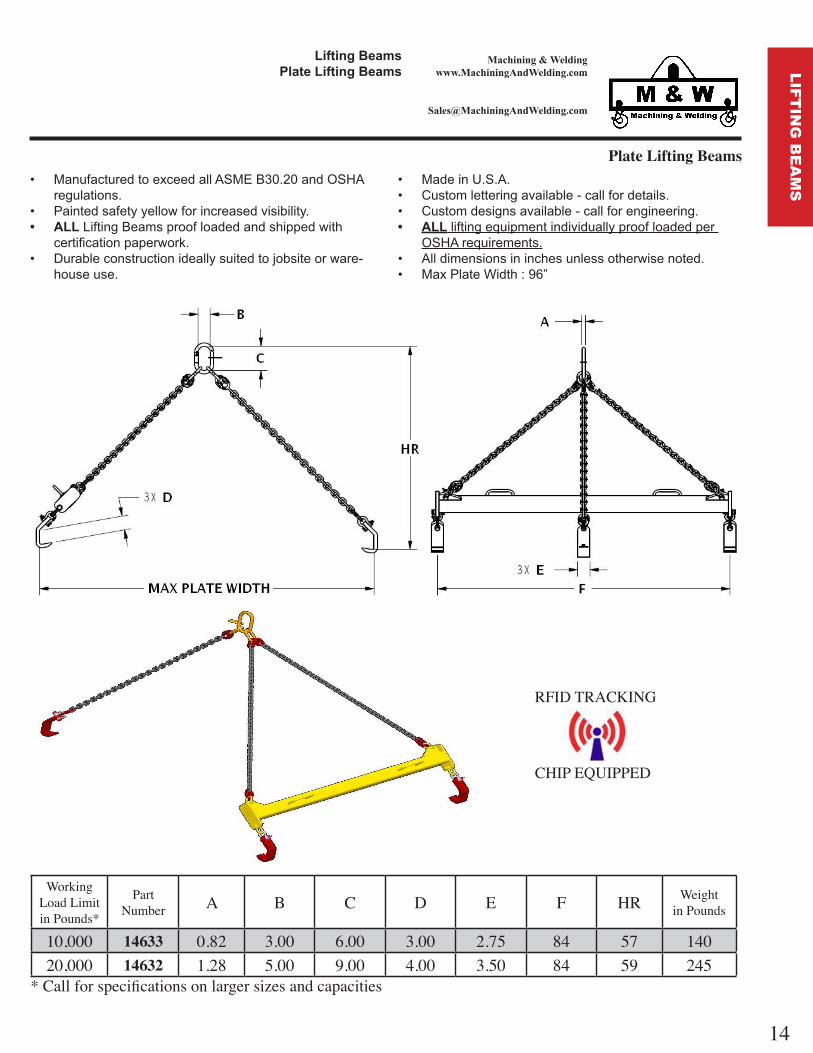
Plate Lifting Beams ManufacturedtoexceedallASMEB30.20andOSHA
regulations. Paintedsafetyyellowforincreasedvisibility. LiftingBeamsproofloadedandshippedwith
certificationpaperwork. Durableconstructionideallysuitedtojobsiteorware-
houseuse.
Working Load Limitin Pounds*
PartNumber A B C D E F HR Weight
in Pounds
10,000 14633 0.82 3.00 6.00 3.00 2.75 84 57 14020,000 14632 1.28 5.00 9.00 4.00 3.50 84 59 245
* Call for specifications on larger sizes and capacities
MadeinU.S.A. Customletteringavailable-callfordetails. Customdesignsavailable-callforengineering. liftingequipmentindividuallyproofloadedper
OSHArequirements. Alldimensionsininchesunlessotherwisenoted. MaxPlateWidth 96”
ft n ea slate ft n ea s
RFID TRACKING
CHIP EQUIPPED
14
LIF
TIN
G B
EA
MS

Machining & Weldingwww.MachiningAndWelding.com
Economy (Fixed Length) Lifting Beams ManufacturedtoexceedallASMEB30.20andOSHA
regulations. Paintedsafetyyellowforincreasedvisibility. LiftingBeamsproofloadedandshippedwith
certificationpaperwork. Durableconstructionideallysuitedtojobsiteorware-
houseuse. Beamssuppliedstandardwithshackleconnections.
WorkingLoad Limitin Pounds*
Part numberHeadroom
Weight
pread in Inches LC B D
24 36 42 48 54 60 66 72 96 120
500Part number
HRWeight
1656110.25
17
1254010.25
22
1502810.25
25
1152510.25
28
1503110.25
30
1503410.25
33
1503710.25
36
1152610.25
38
1152710.25
49
1152810.25
600.75 5.0 3.5
1,000Part number
HRWeight
1614010.25
27
1254610.25
28
1504010.25
30
1152910.25
34
1504310.25
36
1504610.25
40
1504910.25
43
1153010.25
48
1153110.25
63
1153211.25
940.75 5.0 3.5
2,000Part number
HRWeight
1612410.25
26
1505410.25
35
1505710.25
39
1153310.25
47
1506011.25
57
1506311.25
62
1506611.25
67
1153411.25
72
1153513.25124
1153612.25132
1.00 5.0 5.0
4,000Part number
HRWeight
1638111.51
32
1507012.50
50
1507312.50
54
1153712.50
61
1507613.50
75
1507913.50
82
1508213.50
89
1153813.50
96
1153913.50124
1154015.50187
1.00 5.0 5.0
6,000Part number
HRWeight
1638214.77
48
1443315.77
66
1508515.77
73
1443817.77
95
1509217.77104
1509517.77113
1509817.77122
1444217.77130
1444517.77227
1445217.77351
1.50 7.0 6.0
* Call for specifications on larger sizes and capacities
MadeinU.S.A. Customletteringavailable-callfordetails. Customdesignsavailable-callforengineering. liftingequipmentindividuallyproofloadedper
OSHArequirements.
RFID TRACKING
CHIP EQUIPPED
ft n ea sono e en t ft n ea s
15
LIF
TIN
G B
EA
MS

Machining & Weldingwww.MachiningAndWelding.com
ft n ea sa el et fte
Barrel / Bucket Lifter ManufacturedtoexceedallASMEB30.20andOSHA
regulations. Paintedsafetyyellowforincreasedvisibility. Durableconstructionideallysuitedtojobsiteorware-
houseuse. DrumlidMUSTbeproperlysecured Self-adjustingtoliftrimmedsteel,plasticorfiberdrums
MadeinU.S.A. Machinedtoexactingtolerances. Customletteringavailable-callfordetails. Customdesignsavailable-callforengineering. liftingequipmentindividuallyproofloadedper
OSHArequirements.
Working Load Limitin Pounds*
PartNumber
Weightin Pounds A min A max B C D
1,200 16291 22 18.0 29.0 9.1 0.44 13.91,000 16656 17 14.0 20.0 9.1 0.44 11.9
* Call for specifications on larger sizes and capacities
RFID TRACKING
CHIP EQUIPPED
16
LIF
TIN
G B
EA
MS

Machining & Weldingwww.MachiningAndWelding.com
Bulk Container Lifting Beam
ManufacturedtoexceedallASMEB30.20andOSHAregulations.
Paintedsafetyyellowforincreasedvisibility. materialhandlingequipmentproofloadedand
shippedwithcertificationpaperwork. Durableconstructionideallysuitedtojobsiteorware-
houseuse.
MadeinU.S.A. Machinedtoexactingtolerances. Customletteringavailable-callfordetails. Customdesignsavailable-callforengineering. liftingequipmentindividuallyproofloadedper
OSHArequirements.
Lifting BeamsBulk Container Lifting Beam
PartNumber* PREAD A B C D E HR Weight
Working Load Limit in Pounds*
13316 36 1.0 3.0 4.0 5.0 50.9 8.0 105 2,00013310 48 1.0 3.0 4.0 5.0 67.9 8.0 135 2,00013325 36 1.0 3.0 4.0 5.0 50.9 10.0 120 4,00013321 48 1.0 3.0 4.0 5.0 67.9 10.0 150 4,000
*Larger capacities and custom configurations a ailable. Please call for ordering assistance.
RFID TRACKING
CHIP EQUIPPED
17
LIF
TIN
G B
EA
MS

Machining & Weldingwww.MachiningAndWelding.com
Material Stands: Load Tested, Heavy Duty ManufacturedtoexceedallASMEB30.20andOSHA
regulations. Paintedsafetyyellowforincreasedvisibility. Durableconstructionideallysuitedtowarehouseor
manufacturingshop ooruse.
MadeinU.S.A. Customletteringavailable-callfordetails. Customdesignsavailable-callforengineering. MaterialStandsindividuallyproofloadedand
shippedwithcertificationpaperwork. Alldimensionsininchesunlessotherwisenoted.
ate al tan soa Teste ea t ate al tan s
t C annel o o teel to o t ons
RFID TRACKING
CHIP EQUIPPED
Style C
I-Beam Top
Style A
Rectangular Tube Top
Style B
Channel Iron Top
Working Load Limitin Pounds*
PartNumber A B C D E Weight
in Pounds
3,000 13903 42.0 28.0 12.0 20.0 36.0 1405,000 16527 42.0 29.0 12.0 20.0 36.0 1737,000 13777 47.5 24.0 8.0 18.2 41.5 12510,000 16528 47.5 25.0 8.0 19.2 41.5 130
* Call for specifications on larger sizes and capacities
Working Load Limitin Pounds*
PartNumber A B C D E Weight
in Pounds
2,000 15262 35.5 18.0 5.0 13.2 28.0 752,000 15281 35.5 32.0 5.0 20.7 28.0 1055,000 15307 35.5 18.0 6.0 14.3 28.0 905,000 15306 35.5 32.0 6.0 21.5 28.0 1207,000 15309 35.5 18.0 8.0 14.6 28.0 1007,000 15308 35.5 32.0 8.0 22.1 28.0 13510,000 15327 35.5 18.0 10.0 14.5 28.0 12510,000 15312 35.5 32.0 10.0 22.0 28.0 160
* Call for specifications on larger sizes and capacities
Working Load Limitin Pounds*
PartNumber A B C D Weight
in Pounds
5,000 16533 47.5 24.0 4.0 13.4 11010,000 16534 47.5 24.0 6.0 13.3 14515,000 16535 47.5 24.0 5.3 14.3 15020,000 16536 47.5 24.0 6.5 14.4 19530,000 16537 47.5 24.0 8.0 15.5 245
* Call for specifications on larger sizes and capacities
18
LIF
TIN
G B
EA
MS

Machining & Weldingwww.MachiningAndWelding.com
Coil Lifters ManufacturedtoexceedallASMEB30.20andOSHA
regulations. Paintedsafetyyellowforincreasedvisibility. CoilLiftersproofloadedandshippedwith
certificationpaperwork. Durableconstructionideallysuitedtowarehouseuse.
MadeinU.S.A. Customletteringavailable-callfordetails. Customdesignsavailable-callforengineering. liftingequipmentindividuallyproofloadedper
OSHArequirements.
RFID TRACKING
CHIP EQUIPPED
ft n ea sCo l fte s
Working Load Limitin Pounds*
PartNumber Throat HR A B C D E L T Weight
in Pounds
1,000 14463 14.5 18.5 0.81 2.00 3.25 2.25 4.5 8.0 0.50 141,000 14464 14.5 18.5 0.81 2.00 3.25 2.63 6.5 12.0 0.50 152,000 14465 17.5 21.5 0.81 2.00 3.25 2.00 4.5 8.0 0.50 142,000 14466 17.5 21.5 0.81 2.00 3.25 2.50 8.5 16.0 0.50 194,000 14467 19.5 24.6 1.00 2.56 4.06 2.13 4.5 8.0 0.75 274,000 14468 19.5 24.6 1.00 2.56 4.06 3.00 8.5 16.0 0.75 357,000 14469 21.5 28.2 1.18 3.63 5.31 2.87 6.5 12.0 1.00 527,000 14470 21.5 28.2 1.18 3.63 5.31 3.38 8.5 16.0 1.00 5910,000 14471 25.5 32.9 1.50 4.00 5.81 3.50 8.5 16.0 1.25 8710,000 14472 25.5 32.9 1.50 4.00 5.81 4.00 10.5 20.0 1.25 101
* Call for specifications on larger sizes and capacities
19
LIF
TIN
G B
EA
MS
Machining & Weldingwww.MachiningAndWelding.com
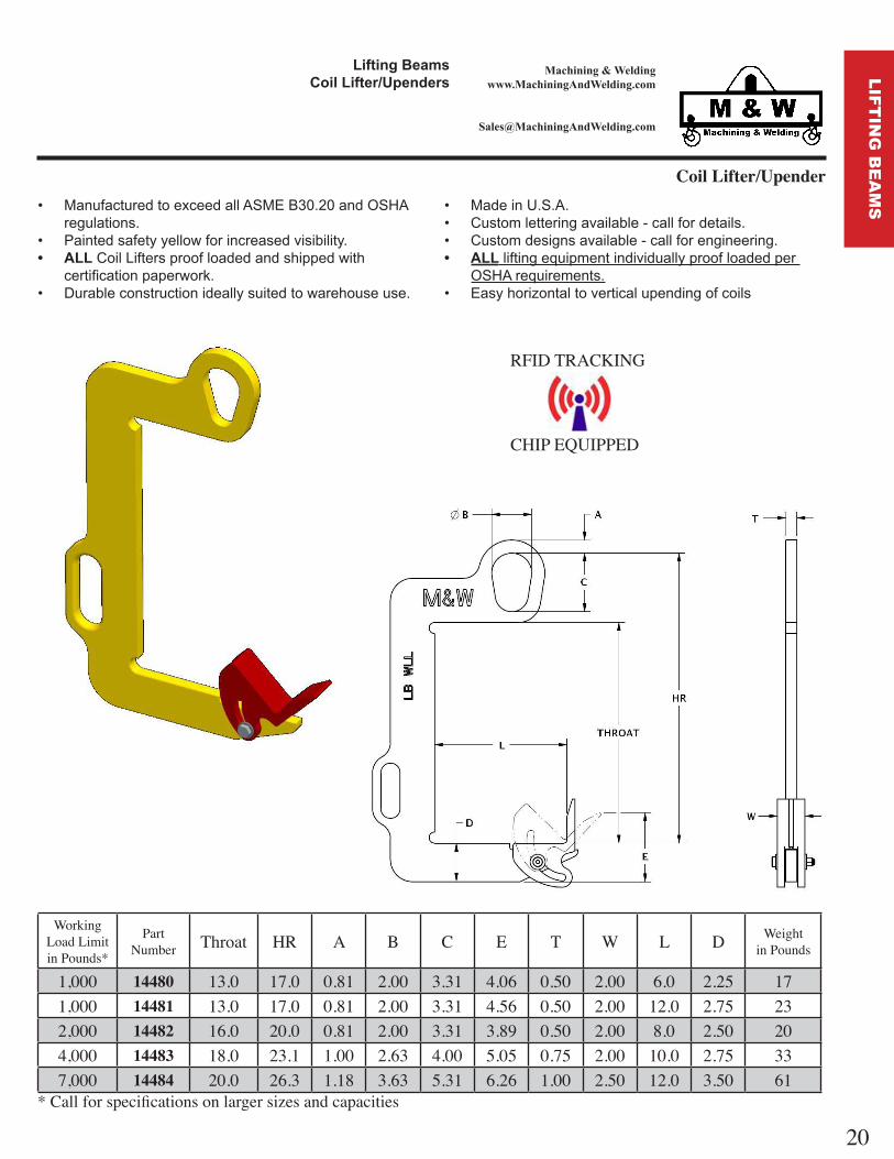
Coil Lifter/Upender
ft n ea sCo l fte en e s
RFID TRACKING
CHIP EQUIPPED
ManufacturedtoexceedallASMEB30.20andOSHAregulations.
Paintedsafetyyellowforincreasedvisibility. CoilLiftersproofloadedandshippedwith
certificationpaperwork. Durableconstructionideallysuitedtowarehouseuse.
MadeinU.S.A. Customletteringavailable-callfordetails. Customdesignsavailable-callforengineering. liftingequipmentindividuallyproofloadedper
OSHArequirements. Easyhorizontaltoverticalupendingofcoils
Working Load Limitin Pounds*
PartNumber Throat HR A B C E T W L D Weight
in Pounds
1,000 14480 13.0 17.0 0.81 2.00 3.31 4.06 0.50 2.00 6.0 2.25 171,000 14481 13.0 17.0 0.81 2.00 3.31 4.56 0.50 2.00 12.0 2.75 232,000 14482 16.0 20.0 0.81 2.00 3.31 3.89 0.50 2.00 8.0 2.50 204,000 14483 18.0 23.1 1.00 2.63 4.00 5.05 0.75 2.00 10.0 2.75 337,000 14484 20.0 26.3 1.18 3.63 5.31 6.26 1.00 2.50 12.0 3.50 61
* Call for specifications on larger sizes and capacities
20
LIF
TIN
G B
EA
MS

Machining & Weldingwww.MachiningAndWelding.com
Small Length Lift Beams - Lift Bale Top ManufacturedtoexceedallASMEB30.20andOSHA
regulations. Paintedsafetyyellowforincreasedvisibility. LiftingBeamsproofloadedandshippedwith
certificationpaperwork. Durableconstructionideallysuitedtowarehouseuse.
MadeinU.S.A. Customletteringavailable-callfordetails. Customdesignsavailable-callforengineering. liftingequipmentindividuallyproofloadedper
OSHArequirements. Suppliedwithshackles.
ft n ea sall en t ft ea s
ft ale To
Working Load Limitin Pounds*
PartNumber
BaleWidth
BaleHeight HR Width Weight
in PoundsBottom Lug
Hole Dia
500 20347 2 4 6.8 12 8 0.50500 20348 2 4 6.8 24 15 0.50500 20349 2 4 6.8 36 21 0.50
2,000 20350 3 5 9.8 12 18 0.852,000 20351 3 5 9.8 24 31 0.852,000 20352 3 5 9.8 36 45 0.856,000 20353 3 5 10.8 12 26 0.956,000 20354 3 5 10.8 24 48 0.956,000 20355 3 5 10.8 36 69 0.95
20,000 20356 4 7 16.1 24 92 1.1220,000 20357 4 7 16.1 36 129 1.12
* Call for specifications on larger sizes and capacities
RFID TRACKING
CHIP EQUIPPED
21
LIF
TIN
G B
EA
MS
Machining & Weldingwww.MachiningAndWelding.com
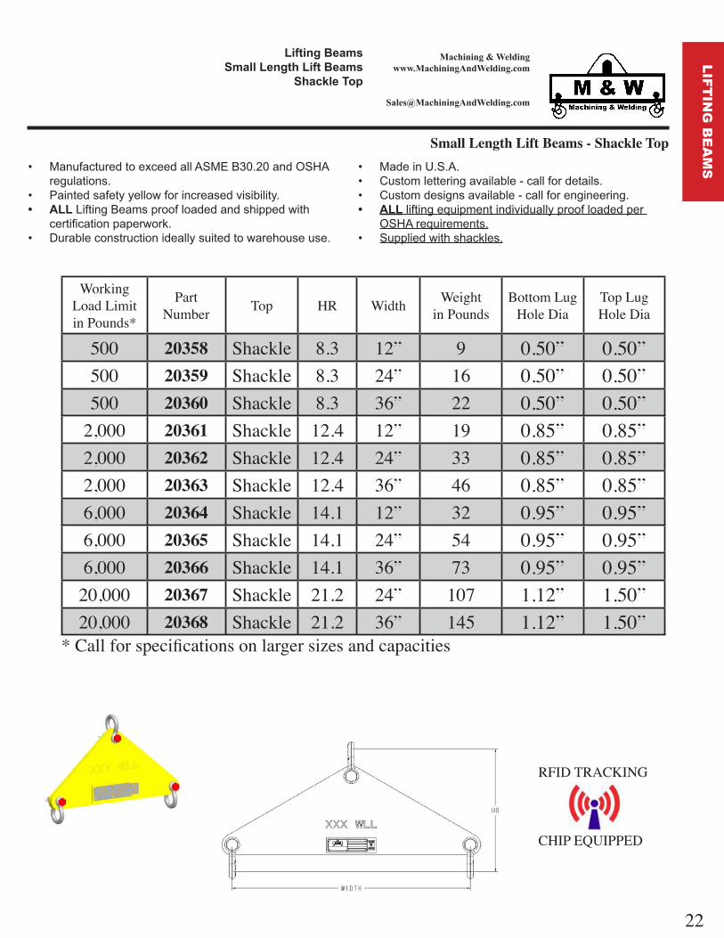
Working Load Limitin Pounds*
PartNumber Top HR Width Weight
in PoundsBottom Lug
Hole DiaTop LugHole Dia
500 20358 hackle 8.3 12 9 0.50 0.50500 20359 hackle 8.3 24 16 0.50 0.50500 20360 hackle 8.3 36 22 0.50 0.50
2,000 20361 hackle 12.4 12 19 0.85 0.852,000 20362 hackle 12.4 24 33 0.85 0.852,000 20363 hackle 12.4 36 46 0.85 0.856,000 20364 hackle 14.1 12 32 0.95 0.956,000 20365 hackle 14.1 24 54 0.95 0.956,000 20366 hackle 14.1 36 73 0.95 0.95
20,000 20367 hackle 21.2 24 107 1.12 1.5020,000 20368 hackle 21.2 36 145 1.12 1.50
* Call for specifications on larger sizes and capacities
ManufacturedtoexceedallASMEB30.20andOSHAregulations.
Paintedsafetyyellowforincreasedvisibility. LiftingBeamsproofloadedandshippedwith
certificationpaperwork. Durableconstructionideallysuitedtowarehouseuse.
MadeinU.S.A. Customletteringavailable-callfordetails. Customdesignsavailable-callforengineering. liftingequipmentindividuallyproofloadedper
OSHArequirements. Suppliedwithshackles.
Small Length Lift Beams - Shackle Top
RFID TRACKING
CHIP EQUIPPED
ft n ea sall en t ft ea s
a le To
22
LIF
TIN
G B
EA
MS

Machining & Weldingwww.MachiningAndWelding.com
Indexing Barrier Lifting Beams ManufacturedtoexceedallASMEB30.20andOSHA
regulations. Paintedsafetyyellowforincreasedvisibility. Liftersproofloadedandshippedwithcertifica-
tionpaperwork. Durableconstructionideallysuitedtojobsiteorware-
houseuse.
MadeinU.S.A. Customletteringavailable-callfordetails. Customdesignsavailable-callforengineering. liftingequipmentindividuallyproofloadedper
OSHArequirements.
ft n ea sn e n a e ft n ea s
a t be Heavy-dutydesigntoholdupto
outdoorenvironmentswherebarri-ersarecommonlyused.
Stainlesssteelindexinglatchmechanism.
Ruggedgrippingpadsswiveltoconformtoload.
Indexinglatchmechanismusesgravitytocausebarrierliftertongstoclosetightly.
Indexinglatchmechanismalsore-leasesthebarrierfromthetongs.
Replacementpadin-stallseasilyandquickly.
optionalOperatorExten-sionHandlekeepsgroundperson-nelawayfromloadwhenadjust-mentisneeded.
Largeliftingeyeaccomodatescranehook.
Handlesbarrierswith6”to12”widthatthetopofthebarrier.
9,000poundcapacity.
RFID TRACKING
CHIP EQUIPPED
Shownwithoptional19 90-40OperatorExtensionHandleononeside.
Shownwithoptional19 90-40OperatorExtensionHandleaddedtobothsides.
23
IND
EX
ING
LIF
TIN
GD
EV
ICE
S

Machining & Weldingwww.MachiningAndWelding.com
Indexing Beam Clamps ManufacturedtoexceedallASMEB30.20andOSHA
regulations. Paintedsafetyyellowforincreasedvisibility. Liftersproofloadedandshippedwithcertifica-
tionpaperwork. Durableconstructionideallysuitedtojobsiteorware-
houseuse.
MadeinU.S.A. Customletteringavailable-callfordetails. Customdesignsavailable-callforengineering. liftingequipmentindividuallyproofloadedper
OSHArequirements. Alldimensionsininchesunlessotherwisenoted.
ft n ea sn e n ea Cla s
RFID TRACKING
CHIP EQUIPPED
Working Load Limitin Pounds*
PartNumber Weight Flange
Width inFlange
Width ax
Flange Thickness
in
Flange Thickness
ax
30,000 20052 180 7 17 1 2 250,000 20051 335 16 24 1 370,000 19913 600 16 36 1 5 8 4
* Call for specifications on larger sizes and capacities
Heavy-dutydesigntoholdupinoutdoorenvironments. Stainlesssteelindexinglatchmechanism. Indexinglatchmechanismusesgravitytocausebeamliftertongstoclosetightly. Indexinglatchmechanismalsoreleasesthebeamfromthetongs. Eliminatestheneedforriggingwhenhandlinglargebeams. Tobeusedonlyforverticalliftingonly. Largeliftingmasterlinkaccomodatescranehooks. Canbeusedinpairstohandlelongerbeams.
24
IND
EX
ING
LIF
TIN
GD
EV
ICE
S

Machining & Weldingwww.MachiningAndWelding.com
Indexing Padded Pipe Lifting Clamps ManufacturedtoexceedallASMEB30.20andOSHA
regulations. Paintedsafetyyellowforincreasedvisibility. Liftersproofloadedandshippedwithcertifica-
tionpaperwork. Durableconstructionideallysuitedtojobsiteorware-
houseuse.
MadeinU.S.A. Customletteringavailable-callfordetails. Customdesignsavailable-callforengineering. liftingequipmentindividuallyproofloadedper
OSHArequirements.
RFID TRACKING
CHIP EQUIPPED
ft n ea sn e n a e e ft n Cla s
Working Load Limitin Pounds*
PartNumber Weight Pipe Dia
inPipe Dia
axax Grip pening
Replacement pad set Part
Number
1,200 20053 26 3.5 5.5 6.4 20053-17
2,000 19911 82 5.5 8.8 10.3 19911-17
4,500 20054 253 8.8 14 16.4 20054-17
10,000 20055 550 14 22 25.5 20055-17* Call for specifications on larger sizes and capacities
Heavy-dutydesigntoholduptooutdoorenviron-ments.
Stainlesssteelindexinglatchmechanism. Ruggedgrippingpadsconformtoload. Indexinglatchmechanismusesgravitytocausepipe
liftertongstoclosetightly. Indexinglatchmechanismalsoreleasesthepipefrom
thetongs. Eliminatestheneedforriggingwhenhandlinglarge
pipe. Tobeusedonlyforverticallifting. Largeliftingshackleaccomodatescranehooksor
supplementaryrigging. Canbeusedinpairstohandlelongerpipes. Replacementpadsetinstallseasilyandquickly.
25
IND
EX
ING
LIF
TIN
GD
EV
ICE
S

Machining & Weldingwww.MachiningAndWelding.com
Large Capacity Shackle End Spreader Beams
ea e ea sa e Ca a t a le n ea s
RFID TRACKING
CHIP EQUIPPED
ManufacturedtoexceedallASMEB30.20andOSHAregulations.
Paintedsafetyyellowforincreasedvisibility. SpreaderBeamsproofloadedandshippedwith
certificationpaperwork. Durableconstructionideallysuitedtowarehouseuse.
MadeinU.S.A. Customletteringavailable-callfordetails. Customdesignsavailable-callforengineering. liftingequipmentindividuallyproofloadedper
OSHArequirements. a les an to n not n l e -pleasecall
forpricing
Ad ustable Large Capacit hackle End preader BeamsWorking
Load Limit in Pounds*
hackleize
odel NumberHeadroom inWeight lbs
utside pread L in Feet*
5 5 7 7 10 10 14 14 20
40,000 1 1 2 Top1 1 2 Bottom
Part NumberHR LB
201277.6350
201267.6410
201257.6560
201247.6760
60,000 1 3 4 Top1 3 4 Bottom
Part NumberHR LB
201327.1370
201317.1490
201307.1660
201297.1890
80,000 2 Top2 Bottom
Part NumberHR LB
201379.3575
201369.3700
201359.3950
201349.3
1,250
100,000 2 Top2 Bottom
Part NumberHR LB
201429.3575
201419.3700
201409.3950
201399.3
1,250* inimum horizontal top rigging angle is 45 on all fixed and ad ustable spreaders. W recommends a minimumhorizontal top rigging angle of 60 . Ad ustable on 3 increments.
Fixed Large Capacit hackle End preader BeamsWorking
Load Limit in Pounds*
odel NumberHeadroom inWeight lbs
utside pread L in Feet*
4 6 8 10 12 16 20
40,000Part Number
HR LB
201658
210
201668
275
201678
330
201688
385
201698
440
201708
550
201718
660
60,000Part Number
HR LB
201727.6255
201737.6315
201747.6385
201757.6450
201767.6510
201777.6635
201787.6770
80,000Part Number
HR LB
201799.8390
201809.8475
201819.8550
201829.8615
201839.8715
201849.8875
201859.8
1,050
100,000Part Number
HR LB
201869.8390
201879.8475
201889.8550
201899.8615
201909.8715
201919.8875
201929.8
1,050* inimum horizontal top rigging angle is 45 on all fixed and ad ustable spreaders. W recommends a minimumhorizontal top rigging angle of 60 .
26
SP
RE
AD
ER
BE
AM
S

Machining & Weldingwww.MachiningAndWelding.com
ea e ea se ea ea s
Fixed Spread Beams ManufacturedtoexceedallASMEB30.20andOSHA
regulations. Paintedsafetyyellowforincreasedvisibility. SpreaderBeamsshippedwithproofloadcertification
paperwork. Durableconstructionideallysuitedtojobsiteorware-
houseuse. Standardwithswivellatchhooks.Topriggingnotinclud-
ed-pleasecallforpricing
MadeinU.S.A. Topriggingavailable-callfordetails. Customletteringavailable-callfordetails. Customdesignsavailable-callforengineering. liftingequipmentindividuallyproofloadedper
OSHArequirements. Minimumhorizontaltopriggingangleof45 . Ideallysuitedforaddingstabilitytocriticallifts.
RFID TRACKING
CHIP EQUIPPED
Working Load Limit in Pounds*
odel NumberHeadroom inWeight lbs
utside pread L in Feet* A inC inE in4 6 8 10 12 16 20
4,000Part Number
HR LB
130947.3730
130977.3750
131008.1290
131038.12110
131068.12130
131098.12172
131128.12215
1.000.50.089
10,000Part Number
HR LB
131168.2336
131198.9887
131228.98112
131258.98140
131289.98190
131319.98250
131349.98306
1.310.751.08
20,000Part Number
HR LB
131389.2555
1314111.00115
1314411.00140
1314711.00170
1315011.00195
1315312.00380
1315612.00470
1.661.001.31
* inimum horizontal top rigging angle is 45 on all fixed and ad ustable spreaders. W recommends a minimumhorizontal top rigging angle of 60 .
27
SP
RE
AD
ER
BE
AM
S

28
Machining & Weldingwww.MachiningAndWelding.com
S p r eader B eam sA dj u s t ab le S p r ead T eles co p ing B eam s
Adjustable Spread Telescoping Beams
RFID TRACKING
CHIP EQUIPPED
• M anu f actu red to ex ceed all A S M E B 30 .20 and O S H A reg u lati ons.
• P ai nted saf ety y ellow f or i ncreased v i si b i li ty .• A L L Spreader Beams shipped with proof load certification
paperw ork .• D u rab le constru cti on i deally su i ted to j ob si te or w are-
h ou se u se.• S tandard w i th sw i v el latch h ook s. T op ri g g i ng not i nclu d-
ed - please call f or pri ci ng
• M ade i n U .S .A .• T op ri g g i ng av ai lab le - call f or detai ls.• C u stom letteri ng av ai lab le - call f or detai ls.• C u stom desi g ns av ai lab le - call f or eng i neeri ng .• A L L li f ti ng eq u i pment i ndi v i du ally proof loaded per
O S H A req u i rements.• M i ni mu m h ori z ontal top ri g g i ng ang le of 4 5°.• I deally su i ted f or addi ng stab i li ty to cri ti cal li f ts.
Working Load Limit in Pounds*
Model NumberHeadroom (in)Weight (lbs)
Outside Spread (L) in Feet* A (in)C (in)E (in)4 - 6 6 - 10 8 - 14 12 - 20
4,000Part Number
HR =LBS =
128055.3780
128225.12120
128135.12155
128295.12235
1.000.500.89
10,000Part Number
HR =LBS =
128346.53130
128426.28190
128486.28250
128536.28365
1.250.751.08
20,000Part Number
HR =LBS =
128647.63185
128727.63265
128807.63345
128857.63510
1.661.001.31
SP
RE
AD
ER
BE
AM
S

29
Machining & Weldingwww.MachiningAndWelding.com
ea e ea sC sto ea e ea
n Ca ts
Custom Spreader Beam End Cap Kits ManufacturedtoexceedallASMEB30.20andOSHA
regulationswhenassembledtospecificationsusingA53GradeBSchedule40pipe.
Paintedsafetyyellowforincreasedvisibility. EndCapsshippedwithproofloadcertificationpa-
perwork. Durableconstructionideallysuitedtojobsiteorware-
houseuse.
MadeinU.S.A. Topriggingavailable-callfordetails. Customletteringavailable-callfordetails. Customdesignsavailable-callforengineering. liftingequipmentindividuallyproofloadedper
OSHArequirements. Minimumhorizontaltopriggingangleof45 W
recommends a minimum angle of 60 .
End Capodel
utside pread in Feet*4 5 6 8 10 12 14 15 16
19499WLL (Tons)
19499-487.5
19499-607
19499-726.5
19499-965.5
19499-1204
19499-1442.9
19499-1682
19499-1801.5
19500WLL (Tons)
19500-4817
19500-6017
19500-7217
19500-9617
19500-12017
19500-14416
19500-16815
19500-18014
19500-19213
19120WLL (Tons)
19120-4839
19120-6039
19120-7239
19120-9639
19120-12039
19120-14438
19120-16836
19120-18036
19120-19235
* inimum horizontal top rigging angle is 45 on all fixed and ad ustable spreaders. W recommends a minimumhorizontal top rigging angle of 60 .
Technical Information
End cap kits are designed for use ith A53 Grade B, chedule 40 pipe bet een the end fittings and must ha e no eld oint irregularities. This steel pipe is idel a ailable, and also a ailable from W. The model 19499 uses a 2 1 2 nominal size pipe, the 19500 uses a 5 nominal size pipe and the 19120 uses an 8 nominal size pipe.
Lengths of pipe bet een end cap kits must be straight to ithin 1 8 from each end, and ends of pipe should be cut s uarel and cleanl from the centerline of the pipe. Lengths of pipe should be free from an factor defects, irregularities, or damage.
Each end of the length of pipe must ha e the correct diameter holes drilled through both ends and in proper alignment through both alls of the pipe. The model 19499 uses a Grade 8 hex head cap scre 5 8 11 ith a length of 4 1 2 . The model 19500 uses a
Grade 8 hex head cap scre 5 8 11 ith a length of 8 . The model 19120 uses a Grade 8 hex head cap scre 1 8 ith a length of 11 1 2 .
SP
RE
AD
ER
BE
AM
S

30
Machining & Weldingwww.MachiningAndWelding.com
ea e ea sC sto ea e ea
n Ca ts
RFID TRACKING
CHIP EQUIPPED
Custom Spreader Beam End Cap Kits
utside pread in Feet* 18 20 22 24 26 28 30 32 34 36
19500-21612
19500-24010
19500-2648
19500-2887
19500-3126
19500-3365
19500-3604.5
19120-21633
19120-24031
19120-26429
19120-28827
19120-31225
19120-33623
19120-36021
19120-38419
19120-40816
19120-43215
Ordering Information
End cap kits are sold in pairs for models 19499, 19500 and 19120. Each cap kit comes complete ith retaining bolts, capacit tags, and indi idual proof load certifications. End cap kits are proof tested and serial numbered in pairs.
Complete spreader beams can be ordered from the chart abo e in standard lengths. For example, a 10 spreader beam ith 39 tons Working Load Limit capacit ould use the 19120 end cap kits and ould be supplied assembled ith the proper A53 Grade B,
chedule 40 pipe. The pipe ould also be tagged and serial numbered. From the chart abo e, the user ould order part number 19120-120. Complete spreader beams are also shipped ith indi idual proof load certification paper ork.
End Capodel
Top hackle
in
Top hackle
ax
Bottom hackle
in
Bottom hackle
ax
WeightperPair
19499 5 8 1 3 8 5 8 1 2819500 7 8 1 5 8 7 8 1 3 82 5019120 1 1 3 4 1 1 1 2 288
SP
RE
AD
ER
BE
AM
S

31
Machining & Weldingwww.MachiningAndWelding.com
o l ft tta entso l ft ft n ea s ns e a le o nt
Forklift Lifting Beams - Inside Shackle Mount ManufacturedtoexceedallASMEB30.20andOSHA
regulations. Paintedsafetyyellowforincreasedvisibility. forkliftattachmentsproofloadedandshippedwith
certificationpaperwork. Durableconstructionideallysuitedtojobsiteorware-
houseuse. Carryinghandleforeasyplacementbypersonnel-
T T T . Checkwithmanufacturerofyourforkliftforloadcapabili-
ties.
Working Load Limit in Pounds*
PartNumber A B C Weight
5,000 11619 19.25 0.810 1.00 3010,000 11620 23.25 1.130 1.25 50
* Call for specifications on larger sizesand capacities
MadeinU.S.A. Machinedtoexactingtolerances. Customletteringavailable-callfordetails. Customdesignsavailable-callforengineering. liftingequipmentindividuallyproofloadedper
OSHArequirements. Includesforkliftrestrainingtabs.
RFID TRACKING
CHIP EQUIPPED
FO
RK
LIF
T A
TTA
CH
ME
NT
S
32
Machining & Weldingwww.MachiningAndWelding.com
o l ft tta entso l ft ft n ea s ts e oo s
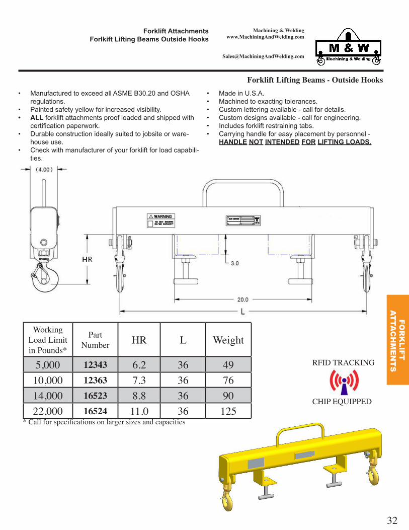
Forklift Lifting Beams - Outside Hooks
Working Load Limit in Pounds*
PartNumber HR L Weight
5,000 12343 6.2 36 4910,000 12363 7.3 36 7614,000 16523 8.8 36 9022,000 16524 11.0 36 125
* Call for specifications on larger sizes and capacities
RFID TRACKING
CHIP EQUIPPED
ManufacturedtoexceedallASMEB30.20andOSHAregulations.
Paintedsafetyyellowforincreasedvisibility. forkliftattachmentsproofloadedandshippedwith
certificationpaperwork. Durableconstructionideallysuitedtojobsiteorware-
houseuse. Checkwithmanufacturerofyourforkliftforloadcapabili-
ties.
MadeinU.S.A. Machinedtoexactingtolerances. Customletteringavailable-callfordetails. Customdesignsavailable-callforengineering. Includesforkliftrestrainingtabs. Carryinghandleforeasyplacementbypersonnel-
T T T
FO
RK
LIF
T A
TTA
CH
ME
NT
S

33
Machining & Weldingwww.MachiningAndWelding.com
o l ft tta entso l ft ft n ea ns e n o nt
Forklift Lifting Beam - Inside Pin Mount
ManufacturedtoexceedallASMEB30.20andOSHAregulations.
Paintedsafetyyellowforincreasedvisibility. forkliftattachmentsproofloadedandshippedwith
certificationpaperwork. Durableconstructionideallysuitedtojobsiteorware-
houseuse. Carryinghandlesforeasyplacementbypersonnel-
T T T . Checkwithmanufacturerofyourforkliftforloadcapabili-
ties.
MadeinU.S.A. Machinedtoexactingtolerances. Customletteringavailable-callfordetails. Customdesignsavailable-callforengineering. liftingequipmentindividuallyproofloadedper
OSHArequirements. HOO NOTINCLUDED. SwivelHookwithbearingavailableforapplications
wheretheloadneedstoswivelwhilesuspended. Includesforkliftrestrainingtabs.
RFID TRACKING
CHIP EQUIPPED
Working Load Limitin Pounds*
PartNumber
Weightin Pounds A B
i el Hook part number
i el Hook ith bearing
part number
Replacement latch part number
Replacement T Handle part
number
Replacement pin part number
5,000 16337 56 36 0.88 1048831 1028614 1096468 11599 1634010,000 16336 75 36 1.00 1048837 1028623 1096515 11599 1634115,000 17000 135 48 1.13 1048865 1028641 1096609 11599 1415820,000 16338 156 36 1.25 1048865 1028641 1096609 11599 16242
* Call for specifications on larger sizes and capacities
FO
RK
LIF
T A
TTA
CH
ME
NT
S

Machining & Weldingwww.MachiningAndWelding.com
o l ft tta entso l ft stable ea e oo
Forklift Lifting Beams - Adjustable Reach Over Boom
ManufacturedtoexceedallASMEB30.20andOSHAregulations.
Paintedsafetyyellowforincreasedvisibility. forkliftattachmentsproofloadedandshippedwith
certificationpaperwork. Durableconstructionideallysuitedtojobsiteorware-
houseuse. Checkwithmanufacturerofyourforkliftforloadcapabili-
ties.
MadeinU.S.A. Machinedtoexactingtolerances. Customletteringavailable-callfordetails. Customdesignsavailable-callforengineering. Includesforkliftrestrainingtabs.
RFID TRACKING
CHIP EQUIPPED
a t be Convertsforkliftintoaerialcrane. ForkWidth 6” Adjustableboomspacingat48”,
60”and 2” Boomcomesequippedwithalloy
swivellatchinghook. Weighs3 5pounds.
34
FO
RK
LIF
T A
TTA
CH
ME
NT
S

Machining & Weldingwww.MachiningAndWelding.com
o l ft tta entso l ft o et fte s
Forklift Pocket Lifters
Working Load Limit in Pounds*
PartNumber A B Fork
Width Weight
3,000 11606 4.5 2.5 4 123,000 11607 5.5 2.5 5 133,000 11608 6.5 2.5 6 143,000 15427 7.5 2.5 7 155,000 14259 4.5 2.5 4 165,000 14250 5.5 2.5 5 185,000 14262 6.5 2.5 6 207,000 15764 6.5 2.5 6 567,000 16642 7.5 3.5 7 567,000 16643 8.5 3.5 8 56
* Call for specifications on larger sizes and capacities
ManufacturedtoexceedallASMEB30.20andOSHAregulations.
Paintedsafetyyellowforincreasedvisibility. forkliftattachmentsproofloadedandshippedwith
certificationpaperwork. Durableconstructionideallysuitedtojobsiteorware-
houseuse. Includesforkliftrestrainingtabs.
MadeinU.S.A. Machinedtoexactingtolerances. Customletteringavailable-callfordetails. Customdesignsavailable-callforengineering. liftingequipmentindividuallyproofloadedper
OSHArequirements. Checkwithmanufacturerofyourforkliftforloadcapa-
bilities.
RFID TRACKING
CHIP EQUIPPED
35
FO
RK
LIF
T A
TTA
CH
ME
NT
S

Machining & Weldingwww.MachiningAndWelding.com
ate al an l nallet fte t stable ft n ase an stable
ft ale
Pallet Lifter with Adjustable Lifting Base and Adjustable Lift Bale
Convertscraneorhoistintoaerialforklift.
Rearguideforoperatorsafety. ForkLength 42” AdjustableForkSpacing 1 -36”
ManufacturedtoexceedallASMEB30.20andOSHAregulations.
Paintedsafetyyellowforincreasedvisibility. materialhandlingequipmentproofloadedand
shippedwithcertificationpaperwork. Durableconstructionideallysuitedtojobsiteorware-
houseuse.
MadeinU.S.A. Machinedtoexactingtolerances. Customletteringavailable-callfordetails. Customdesignsavailable-callforengineering. liftingequipmentindividuallyproofloadedper
OSHArequirements.
Working Load Limitin Pounds*
PartNumber A B C D Weight
in Pounds
4,000 12412 42 17 to 36 2 4 400* Call for specifications on larger sizes and capacities
RFID TRACKING
CHIP EQUIPPED
36
MA
TE
RIA
LH
AN
DL
ING

Machining & Weldingwww.MachiningAndWelding.com
ate al an l nallet fte s
Pallet Lifters
RFID TRACKING
CHIP EQUIPPED
ManufacturedtoexceedallASMEB30.20andOSHAregulations.
Paintedsafetyyellowforincreasedvisibility. materialhandlingequipmentproofloadedand
shippedwithcertificationpaperwork. Durableconstructionideallysuitedtojobsiteorware-
houseuse.
MadeinU.S.A. Machinedtoexactingtolerances. Customletteringavailable-callfordetails. Customdesignsavailable-callforengineering. liftingequipmentindividuallyproofloadedper
OSHArequirements.
Convertscraneorhoistintoaerialforklift.
Rearguideforoperatorsafety. ForkLength 36” ForkSpacing 25” DualLiftBaleadjustment
Working Load Limitin Pounds*
PartNumber
Weightin Pounds
2,000 14511 1904,000 14512 3356,000 14513 4608,000 16664 660
* Call for specifications on larger sizes and capacities
37
PE
RS
ON
NE
LB
AS
KE
TS
MA
TE
RIA
LH
AN
DL
ING

Machining & Weldingwww.MachiningAndWelding.com
ate al an l neele allet fte s
Wheeled Pallet Lifters
Convertscraneorhoistintoaerialforklift.
Rearguideforoperatorsafety. ForkLength 36” ForkSpacing 25” MultipleLiftBaleadjustments.
ManufacturedtoexceedallASMEB30.20andOSHAregulations.
Paintedsafetyyellowforincreasedvisibility. materialhandlingequipmentproofloadedand
shippedwithcertificationpaperwork. Durableconstructionideallysuitedtojobsiteorware-
houseuse.
MadeinU.S.A. Machinedtoexactingtolerances. Customletteringavailable-callfordetails. Customdesignsavailable-callforengineering. liftingequipmentindividuallyproofloadedper
OSHArequirements.
Working Load Limitin Pounds*
PartNumber
Weightin Pounds
4,000 14998 330* Call for specifications on larger sizes and capacities
RFID TRACKING
CHIP EQUIPPED
Convertscraneorhoistintoaerialforklift.
Rearguideforoperatorsafety. ForkLength 36” ForkSpacing 25” DualLiftBaleadjustment.
Working Load Limitin Pounds*
PartNumber
Weightin Pounds
2,000 14538 1954,000 14537 345
* Call for specifications on larger sizes and capacities
38
MA
TE
RIA
LH
AN
DL
ING

Machining & Weldingwww.MachiningAndWelding.com
ate al an l nallet fte s
Pallet Lifters
RFID TRACKING
CHIP EQUIPPED
ManufacturedtoexceedallASMEB30.20andOSHAregulations.
Paintedsafetyyellowforincreasedvisibility. materialhandlingequipmentproofloadedand
shippedwithcertificationpaperwork. Durableconstructionideallysuitedtojobsiteorware-
houseuse.
MadeinU.S.A. Machinedtoexactingtolerances. Customletteringavailable-callfordetails. Customdesignsavailable-callforengineering. liftingequipmentindividuallyproofloadedper
OSHArequirements.
Working Load Limitin Pounds*
PartNumber
Weightin Pounds HR L W D G
2,000 14631 190 57 48 25 24 484,000 14630 760 59 48 25 24 486,000 14629 965 62 48 27 24 48
* Call for specifications on larger sizes and capacities
Convertscraneorhoistintoaerialforklift.
Heavydutyframedesign. Counterbalanceallows
liftertohanglevelwhenempty.
39
MA
TE
RIA
LH
AN
DL
ING

Machining & Weldingwww.MachiningAndWelding.com
o l ft tta entso e sonnel as et
Fork Personnel Basket
ManufacturedtoexceedallASMEB30.20andOSHAregulations.
Paintedsafetyyellowforincreasedvisibility. materialhandlingequipmentproofloadedand
shippedwithcertificationpaperwork. Durableconstructionideallysuitedtojobsiteorware-
houseuse.
MadeinU.S.A. MUSTbetiedtoforkliftduringuse Machinedtoexactingtolerances. Customletteringavailable-callfordetails. Customdesignsavailable-callforengineering. liftingequipmentindividuallyproofloadedper
OSHArequirements.
Working Load Limitin Pounds*
PartNumber
Weightin Pounds Width Depth
1,000 15820 575 48 48600 16805 785 44 75600 16829 800 75 44
* Call for specifications on larger sizes and capacities
RFID TRACKING
CHIP EQUIPPED
40
MA
TE
RIA
LH
AN
DL
ING
Machining & Weldingwww.MachiningAndWelding.com
ate al an l ne ft n oo s
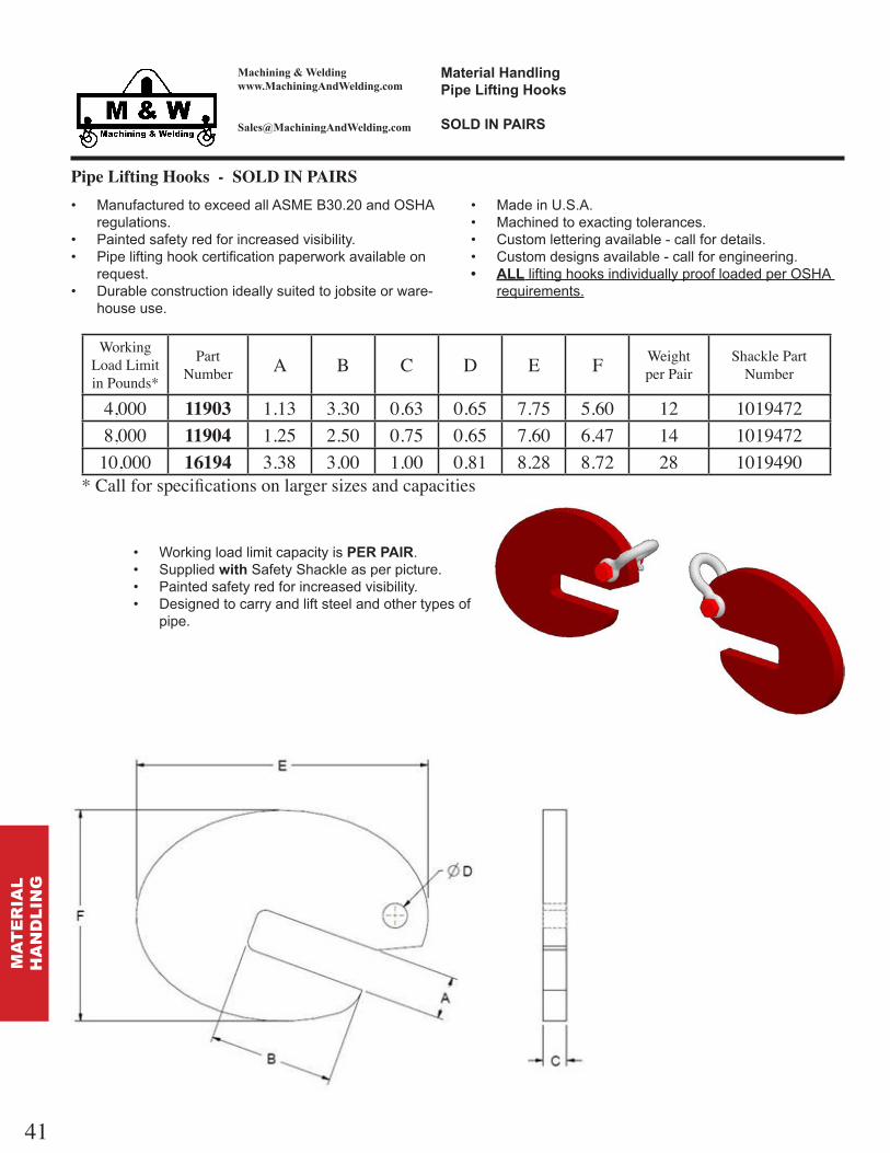
Pipe Lifting Hooks - SOLD IN PAIRS ManufacturedtoexceedallASMEB30.20andOSHA
regulations. Paintedsafetyredforincreasedvisibility. Pipeliftinghookcertificationpaperworkavailableon
request. Durableconstructionideallysuitedtojobsiteorware-
houseuse.
Working Load Limit in Pounds*
PartNumber A B C D E F Weight
per Pairhackle PartNumber
4,000 11903 1.13 3.30 0.63 0.65 7.75 5.60 12 10194728,000 11904 1.25 2.50 0.75 0.65 7.60 6.47 14 1019472
10,000 16194 3.38 3.00 1.00 0.81 8.28 8.72 28 1019490* Call for specifications on larger sizes and capacities
MadeinU.S.A. Machinedtoexactingtolerances. Customletteringavailable-callfordetails. Customdesignsavailable-callforengineering. liftinghooksindividuallyproofloadedperOSHA
requirements.
Workingloadlimitcapacityis . Supplied t SafetyShackleasperpicture. Paintedsafetyredforincreasedvisibility. Designedtocarryandliftsteelandothertypesof
pipe.
41
MA
TE
RIA
LH
AN
DL
ING

Machining & Weldingwww.MachiningAndWelding.com
ate al an l nlate ft n oo s
o se t a e o a e C a n l n s
Plate Lifting Hooks ManufacturedtoexceedallASMEB30.9andOSHA
regulations. Powdercoatpaintedsafetyredforincreasedvisibility. platehooksshippedwithproofloadcertification
paperwork. Durableconstructionideallysuitedtojobsiteorware-
houseuse.Working
Load Limit in Pounds*
PartNumber
Grade 100Chain ize A B C D E F G Weight
eachhackle PartNumber
4,300 11721 9 32 2.00 1.75 2.50 0.63 3.45 0.83 2.50 3 850P8,800 11722 3 8 2.63 3.00 4.31 0.75 5.92 0.95 2.75 6 851P
15,000 11723 1 2 3.50 4.00 4.38 1.00 6.93 1.21 3.50 13 853P22,600 18866 5 8 4.38 5.00 5.44 1.25 8.66 1.60 5.00 27 855P
* Call for specifications on larger sizes and capacities hooks sold individually
MadeinU.S.A. Machinedtoexactingtolerances. Customletteringavailable-callfordetails. Customdesignsavailable-callforengineering. liftinghooksindividuallyproofloadedperOSHA
requirements.
Supplied t SafetyShackle,asperpicture. Powdercoatedred-customcolorsavailableonrequest. Madefromalloymaterial-designedtohandleplatesteel. Availableasliftingcomponentsorattachedtocertified
liftingchainslings. Recommendedtobeusedonlyat45 horizontallifting
angle.
42
MA
TE
RIA
LH
AN
DL
ING

Machining & Weldingwww.MachiningAndWelding.com
ate al an l nnt et l n
T an le an C o e e at onsl n
Synthetic Sling Triangles and Chokers : Aluminum AluminumTriangleandChokerfittingsengineeredtobe
usedonsingle-plycapacityslings. Aluminumresistscorrosion. Aluminumalloydesignedforoverheadliftingapplications.
100%domesticpartsandworkmanship. Machinedtoexactingtolerances. Customletteringavailable-callforlotsizeandprice. Customdimensionsavailable-callforengineering.
Specifications for Aluminum Chokers inimumBreaking
trengthodel
Numberling
WidthDimensions
WeightA B C D E
11473 2 6.16 6.29 2.31 2.24 4.12 .9 16,80011474 3 8.00 8.17 3.31 3.06 5.40 1.5 25,00011475 4 9.40 10.67 3.75 4.25 7.10 2.4 33,50013264 5 11.29 12.00 4.75 5.25 8.19 3.2 40,00011476 6 13.25 14.48 5.50 6.13 9.75 8.5 48,500
8 Call for Quotation10 Call for Quotation12 Call for Quotation
Specifications for Aluminum Triangles inimumBreaking
trengthPart
Numberling
WidthDimensions
WeightA B C D
11469 2 3.94 3.75 2.31 2.25 .4 16,80011470 3 5.31 5.00 3.31 3.06 .6 25,00011471 4 6.75 6.75 3.75 4.25 1.2 33,50013263 5 8.00 8.13 4.75 5.25 1.5 40,00011472 6 9.25 9.38 5.50 6.13 2.0 48,500
8 Call for Quotation10 Call for Quotation12 Call for Quotation
43
MA
TE
RIA
LH
AN
DL
ING

Machining & Weldingwww.MachiningAndWelding.com
ate al an l nnt et l n
T an le an C o e e at onsteel
Synthetic Sling Triangles and Chokers : Steel SteelTriangleandChokerfittingsengineeredtobeused
onsingle-ply,two-ply,three-ply,andfour-plyslings. Powdercoatpaintedforresistancetocorrosion. Alloysteelforoverheadliftingapplications.
Specifications for 2-ply Steel Chokers inimumBreaking
trengthPart
Numberling
WidthDimensions
WeightA B C D E
11462 2 6.16 6.29 2.31 2.24 4.12 2.9 33,00011463 3 8.00 8.17 3.31 3.06 5.40 4.3 44,50011464 4 9.40 10.67 3.75 4.25 7.10 6.8 58,00012338 5 11.18 12.16 4.62 5.15 8.19 9.0 70,00011465 6 13.25 14.48 5.50 6.13 9.75 13.1 84,00012297 8 14.31 16.19 7.13 5.14 12.00 23.0 112,00012296 10 16.88 17.88 8.44 5.26 13.38 27.0 140,00012312 12 20.25 21.44 10.13 6.30 16.00 38.9 160,000
Specifications for 2-ply Steel Triangles inimumBreaking
trengthPart
Numberling
WidthDimensions
WeightA B C D
11455 2 3.94 3.75 2.31 2.25 1.0 33,00011456 3 5.31 5.00 3.31 3.06 1.8 44,50011457 4 6.75 6.75 3.75 4.25 3.2 58,00012337 5 7.70 7.81 4.60 5.13 3.79 70,00011458 6 9.25 9.38 5.50 6.13 5.7 84,00011459 8 11.88 12.25 7.50 8.44 12.06 112,00011460 10 13.25 13.88 8.63 10.88 14.41 140,00011461 12 15.75 16.69 10.31 13.00 20.24 160,000
100%domesticpartsandworkmanship. Machinedtoexactingtolerances. Customletteringavailable-callforlotsizeandprice. Customdimensionsavailable-callforengineering.
Specifications for 4-ply Steel Triangles inimumBreaking
trengthPart
Numberling
WidthDimensions
WeightA B C D
14476 2 4.38 3.75 2.31 2.25 3.3 62,00011938 3 5.81 5.50 3.31 3.06 5.7 93,00012441 4 6.5 6.75 3.75 4.25 7.6 110,000
5 Call for Quotation12440 6 9.15 9.38 5.50 6.13 13.8 165,00012313 8 13.07 12.75 7.50 8.61 21.8 220,00014431 10 15.87 16.00 8.87 11.00 35.2 285,00012543 12 18.75 19.25 10.50 13.00 48.4 330,000
Specifications for 4-ply Steel Chokers inimumBreaking
trengthPart
Numberling
WidthDimensions
WeightA B C D E
14477 2 8.75 7.00 2.25 2.25 4.50 8.4 62,00013368 3 9.13 9.05 3.00 3.31 5.75 11.4 93,00012442 4 10.50 10.67 3.75 4.25 7.10 13.4 110,000
Call for Quotation12439 6 14.12 14.48 5.50 6.13 9.75 25.7 165,00012314 8 16.38 17.00 7.00 5.14 13.14 40.0 220,00014430 10 21.75 24.00 8.50 6.50 16.68 65.4 285,00012544 12 25.50 28.25 10.00 8.00 19.63 86.5 330,000
44
MA
TE
RIA
LH
AN
DL
ING

Machining & Weldingwww.MachiningAndWelding.com
ate al an l ne es l n
T an le an C o e e at ons
Wire Mesh Sling Triangles and Chokers SteelTriangleandChokerfittingsengineeredtobeused
onwiremeshbodyslings. Powdercoatpaintresistscorrosion. Alloysteelforoverheadliftingapplications.
100%domesticpartsandworkmanship. Machinedtoexactingtolerances. Customletteringavailable-callforlotsizeandprice. Customdimensionsavailable-callforengineering.
Specifications for Wire Mesh ChokersWLLertical
WLL90 Degree
Basket
inimumBreaking
trengthodel
Numberling
WidthDimensions
WeightA B C D E
17916 2 6.63 4.50 3.00 2.00 3.25 2.0 2,300 4,600 11,50017926 3 7.31 5.62 3.50 2.50 4.00 3.0 3,500 7,000 17,50017885 4 7.93 6.37 4.00 3.00 4.75 3.5 4,800 9,600 24,00017918 6 9.13 8.38 4.50 3.50 6.25 5.5 7,200 14,400 36,00017920 8 11.38 7.91 6.00 4.50 8.25 9.0 9,600 19,200 48,00017922 10 11.88 13.25 6.25 4.75 10.25 11.5 12,000 24,000 60,00017924 12 12.88 15.50 6.50 5.00 12.36 15.0 14,400 28,800 72,000
Specifications for Wire Mesh TrianglesWLLertical
WLL90 Degree
Basket
inimumBreaking
trengthPart
Numberling
WidthDimensions
WeightA B C D
17915 2 4.55 3.10 3.00 2.00 1.0 2,300 4,600 11,50017925 3 5.18 3.86 3.50 2.50 1.5 3,500 7,000 17,50017884 4 6.30 4.60 4.00 3.00 2.0 4,800 9,600 24,00017917 6 7.00 5.87 4.50 3.50 3.5 7,200 14,400 36,00017919 8 9.00 7.91 6.00 4.50 5.5 9,600 19,200 48,00017921 10 9.25 9.95 6.25 4.75 6.5 12,000 24,000 60,00017923 12 9.75 12.00 6.50 5.00 15.0 14,400 28,800 72,000
45
MA
TE
RIA
LH
AN
DL
ING

Machining & Weldingwww.MachiningAndWelding.com
ate al an l nC a n es l n
T an le an C o e e at ons
Grade 80 Alloy Chain Mesh Sling Triangles and Chokers SteelTriangleandChokerfittingsengineeredtobeused
onchainmeshslings. Powdercoatpaintedforresistancetocorrosion. Alloysteelforoverheadliftingapplications.
Specifications for Chain Mesh Alloy Steel TrianglesWLLertical
WLLChoker
WLLBasketPart
NumberChain
izeChainParts
DimensionsWeight
A B C D18980
7/32
3 6.75 3.00 4.13 2.75 1.0 5,000 5,000 10,00018981 4 6.75 3.75 4.13 2.75 2.5 6,700 6,700 13,40018982 5 8.00 4.50 5.25 3.50 3.2 8,400 8,400 16,80018983 6 8.25 5.25 5.63 3.75 3.8 10,800 10,800 21,60018984
9/32
3 6.62 3.25 4.13 2.75 3.0 8,400 8,400 16,80018985 4 6.62 4.13 4.13 2.75 3.5 11,200 11,200 22,40018986 5 8.00 5.00 5.25 3.50 4.5 14,000 14,000 28,00018987 6 8.25 5.75 5.63 3.75 5.0 16,800 16,800 33,60018988
3/8
3 6.88 4.25 5.25 3.50 5.0 17,000 17,000 34,00018989 4 8.13 6.00 6.50 4.38 7.0 22,700 22,700 45,40018990 5 8.38 6.50 6.25 4.38 9.0 28,400 28,400 56,80018991 6 9.75 8.00 7.88 5.25 12.0 34,000 34,000 68,00018992
1/22 10.38 4.88 7.88 5.25 7.0 19,200 19,200 38,400
18993 3 10.38 6.50 7.88 5.25 13.0 28,800 28,800 57,60018994 4 11.00 8.13 7.88 5.25 15.0 38,400 38,400 76,800
100%domesticpartsandworkmanship. Machinedtoexactingtolerances. Customletteringavailable-callforlotsizeandprice. Customdimensionsavailable-callforengineering.
Specifications for Chain Mesh Alloy Steel ChokersWLLertical
WLLChoker
WLLBasketPart
NumberChain
izeChainParts
DimensionsWeight
A B C D18995
7/32
3 8.75 7.00 4.13 2.75 4.0 5,000 5,000 10,00018996 4 8.75 7.00 4.13 2.75 4.0 6,700 6,700 13,40018997 5 9.75 8.50 5.25 3.50 4.0 8,400 8,400 16,80018998 6 10.25 8.75 5.63 3.75 5.0 10,800 10,800 21,60018999
9/32
3 8.69 7.50 4.13 2.75 5.7 8,400 8,400 16,80019000 4 8.62 7.50 4.13 2.75 5.7 11,200 11,200 22,40019001 5 9.75 8.5 5.25 3.50 7.0 14,000 14,000 28,00019002 6 10.25 9.00 5.63 3.75 7.5 16,800 16,800 33,60019029 3/8 4 11.62 10.00 6.50 4.38 14.5 22,700 22,700 45,400
46
MA
TE
RIA
LH
AN
DL
ING

Machining & Weldingwww.MachiningAndWelding.com
Container Lifting Lugs ManufacturedtoexceedallASMEB30.20andOSHA
regulations. LiftingLugsproofloadedandshippedwith
certificationpaperwork. Durableconstructionideallysuitedtojobsiteorware-
houseuse. Soldindividually
MadeinU.S.A. Customletteringavailable-callfordetails. Customdesignsavailable-callforengineering. liftingequipmentindividuallyproofloadedper
OSHArequirements. Topoflugmustbehorizontaltoshowproperengage-
mentforlifting.
T Typicalcontainerliftwillrequire2leftand2rightlugs.Orwillrequire4straightlugswithappropriatespreader liftingbeamandrigging.
Working Load Limitin Pounds*
PartNumber Color t le Weight
in Pounds
19,000 15373 ello traight 1719,000 15375 Blue Left 1719,000 15445 Red Right 17
ate al an l nConta ne ft n s
47
MA
TE
RIA
LH
AN
DL
ING

Machining & Weldingwww.MachiningAndWelding.com
Insulated Swivel Hooks ManufacturedtoexceedallASMEB30.20andOSHA
regulations. LiftingHooksproofloadedandshippedwith
certificationpaperwork. Durableconstructionideallysuitedtojobsiteorware-
houseuse.
MadeinU.S.A. Customletteringavailable-callfordetails. Customdesignsavailable-callforengineering. liftingequipmentindividuallyproofloadedper
OSHArequirements. Alldimensionsininchesunlessotherwisenoted. Electricallyinsulated-helpseliminatecurrent owthat
maydamagehoistsandliftingequipment
Working Load Limitin Pounds*
PartNumber A B C D E F Weight
in Pounds
4,000 16355 0.75 2.25 3.75 9.0 1.0 2.75 64,500 16358 0.75 2.25 3.81 10.43 1.1 2.75 7
Swivelhookwithlatch CrosbyShur-Loc hook Insulatedto2,000 DC
ate al an l nns late el oo s
48
MA
TE
RIA
LH
AN
DL
ING

Machining & Weldingwww.MachiningAndWelding.com
Hydrant Lifter ManufacturedtoexceedallASMEB30.20andOSHA
regulations. HydrantLifterproofloadedandshippedwith
certificationpaperwork. Durableconstructionideallysuitedtojobsiteorware-
houseuse. Soldindividuallyasparts-seenotebelow
MadeinU.S.A. Customletteringavailable-callfordetails. Customdesignsavailable-callforengineering. liftingequipmentindividuallyproofloadedper
OSHArequirements.
ate al an l nant fte
RFID TRACKING
CHIP EQUIPPED
bottomHydrantlugonly-2,000poundWorkingLoadLimitperpair
topHydrantshortspanbeamonly WorkingLoadLimitof2,000pounds Showninpicturebelow-chainsnotsupplied Liftingshacklessuppliedwith asshowninpictureontheleft
49
MA
TE
RIA
LH
AN
DL
ING

Machining & Weldingwww.MachiningAndWelding.com
Trailer Spotter with Safety Chain ManufacturedtoexceedallASMEB30.20andOSHA
regulations. T a le otte proofloadedandshippedwith
certificationpaperwork. Durableconstructionideallysuitedtojobsiteorware-
houseuse.
MadeinU.S.A. Customletteringavailable-callfordetails. Customdesignsavailable-callforengineering. liftingequipmentindividuallyproofloadedper
OSHArequirements. Alldimensionsininchesunlessotherwisenoted.
ate al an l nT a le otte t afet C a n
RFID TRACKING
CHIP EQUIPPED
completeTrailerSpotterassembly 125poundtotalweight WorkingLoadLimitof1,000pounds Fitsstandard2”receiver 5footsafetychaintosecuretomastofforklift 30”widex30”lengthconvenientforstoragewhennotinuse
Accommodates2”x ”forksize
50
MA
TE
RIA
LH
AN
DL
ING

Machining & Weldingwww.MachiningAndWelding.com
Small Frame Beam Clamps ManufacturedtoexceedallASMEB30.20andOSHA
regulations. Paintedsafetyyellowforincreasedvisibility. Donotsideloadaboveanglesof45 fromvertical. Durableconstructionideallysuitedtojobsiteorware-
houseuse.
MadeinU.S.A. Machinedtoexactingtolerances. Customletteringavailable-callfordetails. Customdesignsavailable-callforengineering. liftingequipmentindividuallyproofloadedper
OSHArequirements.
ate al an l nea Cla s
all a e
RFID TRACKING
CHIP EQUIPPED
Working Load Limit in Pounds*
PartNumber A B C D E F G Weight
aximum Flange
Thickness
inimumFlange
Thickness
aximumFlangeWidth
inimumFlangeWidth
aximumlip erWidth
2,240 13474 10.94 14.59 2.41 0.80 8.75 1.35 8.33 8.3 1.21 0.81 9.50 3.20 8.852,240 13510 15.74 20.52 2.94 0.80 10.63 1.65 13.42 13.8 1.45 0.75 13.50 3.75 11.504,480 13486 10.94 14.59 2.94 0.80 8.75 1.35 8.33 10.4 1.21 0.87 9.60 3.20 9.004,480 13553 15.74 20.52 3.19 0.80 10.63 1.65 13.42 16.1 1.45 0.81 14.50 3.50 14.006,720 13497 15.11 19.53 3.94 1.05 10.13 2.41 12.51 21.4 1.63 1.13 14.00 5.00 13.2511,200 13648 15.11 19.53 4.19 1.38 10.13 2.24 12.51 25.6 1.63 1.13 14.00 4.25 13.00
*Call for specifications on larger sizes and capacities.Indicates beam clamp for use on ide ange beams.
Refertosideloadingtablebelowforreductionfactorsforsideloadingapplications. Clampstobeusedinoverheadbeamattachmentapplicationsonly. Ratingsapplytoclampsonly.Userisresponsibleforengineeringcalculationsforallsupport
steelwork. WARNING Allclampsmustbecorrectlyappliedtothebeambyacompetentpersonandfully
handtightened.Ifindoubt,contactM Wforrecommendations.
Reduction in Working Load Limits hen side loads are applied
Angle from ertical
0 0 15
15 30
30 45
Reduction factor none 20 35 50
51
MA
TE
RIA
LH
AN
DL
ING

Machining & Weldingwww.MachiningAndWelding.com
Large Frame Beam Clamps
ate al an l nea Cla sa e a e
ft n tan a
ManufacturedtoexceedallASMEB30.20andOSHAregulations.
Paintedsafetyyellowforincreasedvisibility. Donotsideloadaboveanglesof45 fromvertical. Durableconstructionideallysuitedtojobsiteorware-
houseuse.
MadeinU.S.A. Machinedtoexactingtolerances. Customletteringavailable-callfordetails. Customdesignsavailable-callforengineering. liftingequipmentindividuallyproofloadedper
OSHArequirements.
RFID TRACKING
CHIP EQUIPPED
Refertosideloadingtablebelowforreductionfactorsforsideloadingapplications. Clampstobeusedinoverheadbeamattachmentapplicationsonly. Ratingsapplytoclampsonly.Userisresponsibleforengineeringcalculationsforallsupport
steelwork. WARNING Allclampsmustbecorrectlyappliedtothebeambyacompetentpersonandfully
handtightened.Ifindoubt,contactM Wforrecommendations.
Reduction in Working Load Limits hen side loads are applied
Angle from ertical
0 0 15
15 30
30 45
Reduction factor none 20 35 50
Working Load Limit in Pounds*
PartNumber A B C D E F G H Weight
aximum
FlangeThickness
aximum
FlangeWidth
inimum
FlangeWidth
aximum
lip er
Width15,680 13659 16.02 20.92 4.72 1.00 10.88 1.25 12.94 3.00 1.75 34.1 1.25 13.75 4.50 13.3822,400 13674 16.02 20.92 4.72 1.25 10.88 1.50 12.94 3.75 2.50 43.1 1.25 13.75 4.50 13.38
*Call for specifications on larger sizes and capacities.
52
MA
TE
RIA
LH
AN
DL
ING

Machining & Weldingwww.MachiningAndWelding.com
ate al an l na Ton fte
Bar Tong Lifter ManufacturedtoexceedallASMEB30.20andOSHA
regulations. materialhandlingequipmentshippedwithproofload
certificationpaperwork. Durableconstructionideallysuitedtojobsiteorware-
houseuse.
Working Load Limit in Pounds*
PartNumber A B C D Weight
1,000 11855 0 4 6.00 1.69 0.63 122,000 16890 7 12 6.00 2.00 0.75 554,000 11902 4 7.5 6.00 2.00 0.75 41
* Call for specifications on larger sizes and capacities
MadeinU.S.A. Customletteringavailable-callfordetails. Customdesignsavailable-callforengineering. liftingequipmentindividuallyproofloadedper
OSHArequirements. Idealformovingroundbarsandpipe.
RFID TRACKING
CHIP EQUIPPED
53
MA
TE
RIA
LH
AN
DL
ING

Machining & Weldingwww.MachiningAndWelding.com
ate al an l neel ft n T n n
Reel Lifting and Turning
ManufacturedtoexceedallASMEB30.20andOSHAregulations.
materialhandlingequipmentproofloadedandshippedwithcertificationpaperwork.
Durableconstructionideallysuitedtojobsiteorware-houseuse.
MadeinU.S.A. Machinedtoexactingtolerances. Customletteringavailable-callfordetails. Customdesignsavailable-callforengineering. liftingequipmentindividuallyproofloadedper
OSHArequirements.
WorkingLoadLimitstampedoneachlifter. Safelyallowspersonnelto ipreelsfromrollingtonon-
rollingpositionquicklyandeasily. to be se onl f o n eels f o oll n
to non oll n os t on ot to be se fo a o t
Working Load Limit in Pounds*
PartNumber A B C D Arbor Dia Weight
500 19455 0.75 1.05 n a 1.00 1 1 4 2 33,000 12782 1.50 2.00 2.75 1.66 2 4 74,500 13037 2.00 2.63 2.75 2.38 3 6 14
* Call for specifications on larger sizes and capacities
54
MA
TE
RIA
LH
AN
DL
ING

Machining & Weldingwww.MachiningAndWelding.com
ate al an l neel T n n a t oo
Reel Turning Pay-Out Hook
Working Load Limit in Pounds*
PartNumber A B C D hackle
ize EWeight
2,200 10022 4.3 3.0 4.5 3.5 9.6 12 7 16 6.57,100 10641 6.0 3.3 4.0 3.5 10.7 13.1 5 8 9.6
* Call for specifications on larger sizes and capacities
ManufacturedtoexceedallASMEB30.20andOSHAregulations.
Powdercoatpaintedsafetyredforincreasedvisibility. materialhandlingequipmentproofloadedand
shippedwithcertificationpaperwork. Durableconstructionideallysuitedtojobsiteorware-
houseuse.
MadeinU.S.A. Machinedtoexactingtolerances. Customletteringavailable-callfordetails. Customdesignsavailable-callforengineering. liftingequipmentindividuallyproofloadedper
OSHArequirements.
WorkingLoadLimitstampedoneachhook. Safelyallowspersonneltopay-outreelsfromrollingposi-
tionquicklyandeasilywithorwithoutrollingpipe. Safetylatchforpositiveconnectiononpipeinsidereel. Shackletopconnectionallowsformultipleconnections. NOTE Shacklenotincluded. SoldasEACH-WLLperhook
55
MA
TE
RIA
LH
AN
DL
ING

Machining & Weldingwww.MachiningAndWelding.com
ate al an l neel ft n oo
Reel Turning and Pay-Out Hooks
Working Load Limit in Pounds*
PartNumber Weight
3,000 13409 5* Call for specifications on larger sizes and capacities
ManufacturedtoexceedallASMEB30.20andOSHAregulations.
Powdercoatpaintedsafetyredforincreasedvisibility. Proofloadcertificatesavailableuponrequest. Durableconstructionideallysuitedtojobsiteuse.
MadeinU.S.A. 4%ondimensions. Customletteringavailable-callfordetails. Customdesignsavailable-callforengineering.
3,000poundWorkingLoadLimitperhook.
6,000poundWorkingLoadLimitat60degreeswhenusedinpairs.
1”diameterhookfitsmostanyreelopening.
Hookdesignpermitsalmostuniver-salusenomatterthereelsizeorconfiguration.
Shownon2-legbridlesling. Optional2-legbridleslingavailable
uponrequest.Callfordetails.
56
MA
TE
RIA
LH
AN
DL
ING

Machining & Weldingwww.MachiningAndWelding.com
ate al an l nCon ete e ft n ent
Concrete Pipe Lifting Equipment ManufacturedtoexceedallASMEB30.20andOSHA
regulations. Wireropeliftingslingavailable-callforquote. Wireropeferrulesavailableseparately-orderbypart
numberandwireropediameter. Durableconstructionideallysuitedtojobsiteuse.
MadeinU.S.A. Machinedtoexactingtolerances. Customletteringavailable-calldetails. Efficientmethodforhandlingofwaterandsewer
concretepipes.
Capacitin Pounds*
Teacup Part
Number
Wire RopeDiameter Color
Wire RopeFerrule Part
Number
4,400 11575 1 2 5.00 6.00 3.50 range 123706,800 11576 5 8 5.00 6.00 3.50 Gra 123719,800 11577 3 4 5.00 6.00 3.50 Blue 12372
13,200 11578 7 8 5.00 6.00 3.50 Black 1237317,000 11579 1 5.00 6.00 4.25 Red 1237420,000 11580 1 1 8 5.00 6.00 4.25 Green 1237526,000 11581 1 1 4 6.00 7.50 5.00 ello 1237630,000 11582 1 3 8 6.00 7.50 5.00 White 1238036,000 11583 1 1 2 6.00 7.50 5.50 range 1238150,000 11783 1 3 4 6.00 7.50 5.50 Bro n 12421
* Call for specifications on larger sizes and capacities
57
MA
TE
RIA
LH
AN
DL
ING

Machining & Weldingwww.MachiningAndWelding.com
Concrete Pipe Lifting Equipment : Button Stops
ate al an l nCon ete e ft n ent
tton to s fo e o eo n on n t on t Con ete e Tea s
Button top Part
Number
Wire Rope
DiameterA B C D Teacup
ColorTeacup
PartNumber
16686 1 2 1.25 2.00 1.13 2.25 range 1157516688 5 8 1.563 2.63 1.38 3.00 Gra 1157616689 3 4 1.688 3.00 1.50 3.50 Blue 1157716690 7 8 2.00 3.63 1.75 4.25 Black 1157816691 1 2.25 4.25 2.00 4.75 Red 1157916692 1 1 8 2.50 4.75 2.25 5.25 Green 1158016693 1 1 4 2.75 5.25 2.50 5.88 ello 11581
* Call for specifications on larger sizes and capacities
ManufacturedtoexceedallASMEB30.20andOSHAregulations.
Wireropeliftingslingavailable-callforquote. SuitableforusewithconcretepipeTeacuplifters
MadeinU.S.A. Machinedtoexactingtolerances. Efficientmethodforhandlingofwaterandsewer
concretepipes.
58
MA
TE
RIA
LH
AN
DL
ING

Machining & Weldingwww.MachiningAndWelding.com
ate al an l nan ole To le e
Manhole Toggle Key ManufacturedtoexceedallASMEB30.20andOSHA
regulations. Paintedsafetyyellowforincreasedvisibility. Durableconstructionideallysuitedtojobsiteorware-
houseuse. Togglecertificatesavailableuponrequest.
Working Load Limitin Pounds
PartNumber Weight A B
3,500 12434 3 4.0 1.253,200 16300 5 8.25 1.132,200 17761 6 11.0 1.253,400 19123 5 6.0 1.25
MadeinU.S.A. Machinedtoexactingtolerances. Customletteringavailable-callfordetails. Customdesignsavailable-callforengineering. manholetogglesindividuallyproofloadedper
OSHArequirements.
59
MA
TE
RIA
LH
AN
DL
ING

Machining & Weldingwww.MachiningAndWelding.com
Clamp-On Bucket Forks ManufacturedtoexceedallASMEB30.20andOSHA
regulations. Paintedsafetyyellowforresistancetocorrosion. Durableconstructionideallysuitedtojobsiteorware-
houseuse.
Capacitin Pounds*
PartNumber A LC B C Weight
950 11914 36 18 2 3 341,250 12194 42 21 2 4 622,750 12242 48 24 3 5 107
* Call for specifications on larger sizes and capacities
100%domesticpartsandworkmanship. Machinedtoexactingtolerances. Customletteringavailable-callforlotsize. Customdimensionsavailable-callforengineering. ol n all
RFID TRACKING
CHIP EQUIPPED
ate al an l nCla n et o s
60
MA
TE
RIA
LH
AN
DL
ING

Machining & Weldingwww.MachiningAndWelding.com
ate al an l nan ole lee e fte
Manhole Sleeve Lifter ManufacturedtoexceedallASMEB30.20andOSHA
regulations. materialhandlingequipmentshippedwithproofload
certificationpaperwork. Durableconstructionideallysuitedtojobsiteorware-
houseuse.
Working Load Limit in Pounds
PartNumber Weight
710 12432 13
MadeinU.S.A. Customletteringavailable-callfordetails. Customdesignsavailable-callforengineering. liftingequipmentindividuallyproofloadedper
OSHArequirements.
Idealforfastandeasyplacementofcastmanholesleevesinthefieldorwarehouse.
Optional2-legor3-legadjustabletopriggingavailableuponrequest.Callfordetails.
Optionalthirdlegwithmanholeplacementhookavailableuponrequest.Callfordetails.
RFID TRACKING
CHIP EQUIPPED
61
MA
TE
RIA
LH
AN
DL
ING

Machining & Weldingwww.MachiningAndWelding.com
Material Baskets with Fixed Sides ManufacturedtoexceedallASMEB30.20andOSHA
regulations. Paintedsafetyyellowforresistancetocorrosion. materialbasketsshippedwithproofloadcertification
paperwork. Durableconstructionideallysuitedtojobsiteorware-
houseuse.
MadeinU.S.A. Machinedtoexactingtolerances. Customletteringavailable-callfordetails. Customdesignsavailable-callforengineering. liftingequipmentindividuallyproofloadedper
OSHArequirements. T T T
RFID TRACKING
CHIP EQUIPPED
ate al as etse e ate al as ets
Capacitin Pounds*
PartNumber A B C D Weight
2,500 11857 87 72 48 24 7004,000 15211 96 81 48 24 720
* Call for specifications on larger sizes and capacities
62
MA
TE
RIA
LB
AS
KE
TS

Machining & Weldingwww.MachiningAndWelding.com
Material Basket with Drop Side ManufacturedtoexceedallASMEB30.20andOSHA
regulations. Paintedsafetyyellowforresistancetocorrosion. materialbasketsshippedwithproofloadcertification
paperwork. Durableconstructionideallysuitedtojobsiteorware-
houseuse.
Capacitin Pounds*
PartNumber A B C D Weight
2,500 12902 48 28 3.6 7.6 4102,500 17594 36 28 3.6 7.6 400
* Call for specifications on larger sizes and capacities
MadeinU.S.A. Machinedtoexactingtolerances. Customletteringavailable-callfordetails. Customdesignsavailable-callforengineering. liftingequipmentindividuallyproofloadedper
OSHArequirements. T T T
RFID TRACKING
CHIP EQUIPPED
ate al as etsate al as et t o e
63
MA
TE
RIA
LB
AS
KE
TS

Machining & Weldingwww.MachiningAndWelding.com
Material Baskets with Fixed Sides ManufacturedtoexceedallASMEB30.20andOSHA
regulations. Paintedsafetyyellowforresistancetocorrosion. materialbasketsshippedwithproofloadcertification
paperwork. Durableconstructionideallysuitedtojobsiteorware-
houseuse.
MadeinU.S.A. Machinedtoexactingtolerances. Customletteringavailable-callfordetails. Customdesignsavailable-callforengineering. liftingequipmentindividuallyproofloadedper
OSHArequirements. T T T
RFID TRACKING
CHIP EQUIPPED
ate al as etse e ate al as ets
Capacitin Pounds*
PartNumber A B C D E F Weight
2,500 11827 36 24 4.0 6.0 36 36 3202,500 11829 48 24 4.0 8.0 48 48 3602,500 16006 60 24 4.0 8.0 60 48 500
* Call for specifications on larger sizes and capacities
64
MA
TE
RIA
LB
AS
KE
TS

Machining & Weldingwww.MachiningAndWelding.com
Personnel Basket with optional Test Weight and Suspension Rigging Paintedsafetyyellowforincreasedvisibility. PersonnelBasketsshippedwithproofloadcertifica-
tionpaperwork. Durableconstructionideallysuitedtojobsiteorware-
houseuse.
MadeinU.S.A. Machinedtoexactingtolerances. Customletteringavailable-callfordetails. Customdesignsavailable-callforengineering. Liftingpointshacklesincludedwithsuspensionrigging
e sonnel as ett o t onal Test e t an s ens on n
65
PE
RS
ON
NE
LB
AS
KE
TS

Machining & Weldingwww.MachiningAndWelding.com
MeetsorexceedsASMEB30.23specifications. EACHpersonnelbasketindividuallyloadtestedwithinspectionandOSHAcertificationpaperworkincluded.
Sidesenclosedwithsolidmetaltotheintermediaterail. Grabrailonentireperimeter. Non-slip,diamondplatesteel oor. Inwardswing,self-closinglockingaccessdoor.Heavy-dutyhingeandlatchstandardonallmodels.
GuardrailsystemcomplieswithOSHA29CFRPart1926.1421(e)6and1926.1421(e) .
Permanentidentification dataplatestandardonallmodels. Productliabilityinsurancecertificateavailableuponrequest. Solid,removableroofdesignisstandardonallmodels-keepsweatheroffpersonneltocomplywithOSHA1926.1421(e)10.
Permanenttie-offpointsformaterialsandtoolstocomplywithOSHA1926.1431(e).
Liftingpointshacklesnotincluded.
RFID TRACKING
CHIP EQUIPPED
TT
Pin-on,removabletestweight. 4-legsuspensionriggingbridlewithBolt-Typeanchorshackles.
Expandedmetalsidesand ortop.
Capacitin Pounds*
BasketPart
NumberWeight A Test Weight
Part Number
uspensionBridle Part
Number
Test WeightQuantit
500 14347 735 34 x 40 14369 15189 11,000 12741 945 48 12748 15189 11,500 12757 1200 72 12766 15190 12,000 12755 1525 94 12748 15191 2
* Call for specifications on larger sizes and capacities
Personnel Basket with optional Test Weight and Suspension Rigging
Specifications:
e sonnel as ett o t onal Test e t an s ens on n
66
PE
RS
ON
NE
LB
AS
KE
TS

Machining & Weldingwww.MachiningAndWelding.com
Round Personnel Basket with optional Test Weight and Suspension Rigging Paintedsafetyyellowforincreasedvisibility. PersonnelBasketsshippedwithproofloadcertifica-
tionpaperwork. Durableconstructionideallysuitedtojobsiteorware-
houseuse.
MadeinU.S.A. Machinedtoexactingtolerances. Customletteringavailable-callfordetails. Customdesignsavailable-callforengineering. Liftingpointshacklesnotincluded.
Capacitin Pounds*
BasketPart
NumberWeight utside
DiameterTest WeightPart Number ides Test Weight
Quantit
500 16465 550 33 15729 Half 1500 16466 550 33 15729 Full 1
* Call for specifications on larger sizes and capacities
o n e sonnel as ett o t onal Test e t an s ens on n
67
PE
RS
ON
NE
LB
AS
KE
TS

Machining & Weldingwww.MachiningAndWelding.com
MeetsorexceedsASMEB30.23specifications. EACHpersonnelbasketindividuallyloadtestedwithinspec-tionandOSHAcertificationpaperworkincluded.
Sidesenclosedwithexpandedmetaltotheintermediaterail. Grabrailonentireperimeter. Non-slip,diamondplatesteel oor. Outwardswing,self-closinglockingaccessdoor.Heavy-dutyhingeandlatchstandardonallmodels.
GuardrailsystemcomplieswithOSHA29CFRPart1926.1421(e)6and1926.1421(e) .
Permanentidentification dataplatestandardonallmodels. Productliabilityinsurancecertificateavailableuponrequest. SolidroofdesignisavailabletokeepweatheroffpersonneltocomplywithOSHA1926.1421(e)10.
Permanenttie-offpointsformaterialsandtoolstocomplywithOSHA1926.1431(e).
Liftingpointshacklesnotincluded.
RFID TRACKING
CHIP EQUIPPED
TT
Pin-on,removabletestweight. 3-legsuspensionriggingbridlewithBolt-Typeanchorshackles( a t
be ). Solidmetalroof.
Round Personnel Basket with optional Test Weight and Suspension Rigging
Specifications:
o n e sonnel as ett o t onal Test e t an s ens on n
68
PE
RS
ON
NE
LB
AS
KE
TS

Machining & Weldingwww.MachiningAndWelding.com
Lifting Hooks : Alloy Steel J-Hooks Eye Style 9
Lifting HooksAlloy Steel J-Hooks
Eye Style 9
aterial Diameter in
Inches*
Part NumberC D E
tandard Allo t le 9 teel Hooks B length
5 6 7 8 9 10 12 14
1 4WLL
100Pounds
Part NumberC D E
19475-51.001.250.87
19475-61.001.250.87
19475-71.001.250.87
19475-81.001.250.87
19475-91.001.250.87
19475-101.001.250.87
19475-121.001.250.87
19475-141.001.250.87
5 16WLL
250Pounds
Part NumberC D E
19476-51.001.250.87
19476-61.001.250.87
19476-71.001.250.87
19476-81.001.250.87
19476-91.001.250.87
19476-101.001.250.87
19476-121.001.250.87
19476-141.001.250.87
3 8WLL
365Pounds
Part NumberC D E
19477-51.001.501.12
19477-61.001.501.12
19477-71.001.501.12
19477-81.001.501.12
19477-91.001.501.12
19477-101.001.501.12
19477-121.001.501.12
19477-141.001.501.12
1 2WLL
650Pounds
Part NumberC D E
19478-51.002.001.50
19478-61.002.001.50
19478-71.002.001.50
19478-81.002.001.50
19478-91.002.001.50
19478-101.002.001.50
19478-121.002.001.50
19478-141.002.001.50
5 8WLL1,000
Pounds
Part NumberC D E
19479-51.002.501.87
19479-61.002.501.87
19479-71.002.501.87
19479-81.002.501.87
19479-91.002.501.87
19479-101.002.501.87
19479-121.002.501.87
19479-141.002.501.87
3 4WLL1,450
Pounds
Part NumberC D E
19480-61.003.002.25
19480-71.003.002.25
19480-81.003.002.25
19480-91.003.002.25
19480-101.003.002.25
19480-121.003.002.25
19480-141.003.002.25
7 8WLL1,900
Pounds
Part NumberC D E
19481-81.003.502.62
19481-91.003.502.62
19481-101.003.502.62
19481-121.003.502.62
19481-141.003.502.62
1WLL2,600
Pounds
Part NumberC D E
19482-101.254.003.00
19482-121.254.003.00
19482-141.254.003.00
*Larger capacities and custom configurations a ailable. Please call for ordering assistance.
ManufacturedtoexceedallASMEB30.20andOSHAregulations.
Corrosionresistantfinish. Durableconstructionideallysuitedtojobsiteorware-
houseuse. MadeinU.S.A. Maximumusetemperatureis400 F.
4%ondimensions. Customletteringavailable-callfordetails. Customdesignsavailable-callforengineering. ll e es el e nless ot e se s e e . Squareandhexstockavailable. Paintlinehooksalsoavailable-callfordetails. Proofloadcertificatesavailableuponrequest.
69
HO
OK
S

Machining & Weldingwww.MachiningAndWelding.com
Lifting Hooks : Alloy Steel J-Hooks Eye Style A
Lifting HooksAlloy Steel J-Hooks
Eye Style A
ManufacturedtoexceedallASMEB30.20andOSHAregulations.
Corrosionresistantfinish. Durableconstructionideallysuitedtojobsiteorware-
houseuse. MadeinU.S.A. Maximumusetemperatureis400 F.
4%ondimensions. Customletteringavailable-callfordetails. Customdesignsavailable-callforengineering. ll e es el e nless ot e se s e e Squareandhexstockavailable. Paintlinehooksalsoavailable-callfordetails. Proofloadcertificatesavailableuponrequest.
aterial Diameter in
Inches*
Part NumberC D E
tandard Allo t le A teel Hooks B length
5 6 7 8 9 10 12 14
1 4WLL
100Pounds
Part NumberC D E
11621-51.001.250.87
11621-61.001.250.87
11621-71.001.250.87
11621-81.001.250.87
11621-91.001.250.87
11621-101.001.250.87
11621-121.001.250.87
11621-141.001.250.87
5 16WLL
250Pounds
Part NumberC D E
11622-51.001.250.87
11622-61.001.250.87
11622-71.001.250.87
11622-81.001.250.87
11622-91.001.250.87
11622-101.001.250.87
11622-121.001.250.87
11622-141.001.250.87
3 8WLL
365Pounds
Part NumberC D E
11623-51.001.501.12
11623-61.001.501.12
11623-71.001.501.12
11623-81.001.501.12
11623-91.001.501.12
11623-101.001.501.12
11623-121.001.501.12
11623-141.001.501.12
1 2WLL
650Pounds
Part NumberC D E
11624-51.002.001.50
11624-61.002.001.50
11624-71.002.001.50
11624-81.002.001.50
11624-91.002.001.50
11624-101.002.001.50
11624-121.002.001.50
11624-141.002.001.50
5 8WLL1,000
Pounds
Part NumberC D E
11625-51.002.501.87
11625-61.002.501.87
11625-71.002.501.87
11625-81.002.501.87
11625-91.002.501.87
11625-101.002.501.87
11625-121.002.501.87
11625-141.002.501.87
3 4WLL1,450
Pounds
Part NumberC D E
11626-61.003.002.25
11626-71.003.002.25
11626-81.003.002.25
11626-91.003.002.25
11626-101.003.002.25
11626-121.003.002.25
11626-141.003.002.25
7 8WLL1,900
Pounds
Part NumberC D E
11627-81.003.502.62
11627-91.003.502.62
11627-101.003.502.62
11627-121.003.502.62
11627-141.003.502.62
1WLL2,600
Pounds
Part NumberC D E
11628-101.254.003.00
11628-121.254.003.00
11628-141.254.003.00
*Larger capacities and custom configurations a ailable. Please call for ordering assistance.
70
HO
OK
S

Machining & Weldingwww.MachiningAndWelding.com
Lifting Hooks : Alloy Steel J-Hooks Eye Style B
Lifting HooksAlloy Steel J-Hooks
Eye Style B
ManufacturedtoexceedallASMEB30.20andOSHAregulations.
Corrosionresistantfinish. Durableconstructionideallysuitedtojobsiteorware-
houseuse. MadeinU.S.A. Maximumusetemperatureis400 F.
4%ondimensions. Customletteringavailable-callfordetails. Customdesignsavailable-callforengineering. Alleyesweldedunlessotherwisespecified. Squareandhexstockavailable. Paintlinehooksalsoavailable-callfordetails. Proofloadcertificatesavailableuponrequest.
aterial Diameter in
Inches*
Part NumberC D E
tandard Allo t le B teel Hooks B length
6 7 8 9 10 12 14
1 4WLL
100Pounds
Part NumberC D E
11637-61.001.250.87
11637-71.001.250.87
11637-81.001.250.87
11637-91.001.250.87
11637-101.001.250.87
11637-121.001.250.87
11637-141.001.250.87
5 16WLL
250Pounds
Part NumberC D E
11638-61.001.250.87
11638-71.001.250.87
11638-81.001.250.87
11638-91.001.250.87
11638-101.001.250.87
11638-121.001.250.87
11638-141.001.250.87
3 8WLL
365Pounds
Part NumberC D E
11639-61.001.501.12
11639-71.001.501.12
11639-81.001.501.12
11639-91.001.501.12
11639-101.001.501.12
11639-121.001.501.12
11639-141.001.501.12
1 2WLL
650Pounds
Part NumberC D E
11640-61.002.001.50
11640-71.002.001.50
11640-81.002.001.50
11640-91.002.001.50
11640-101.002.001.50
11640-121.002.001.50
11640-141.002.001.50
5 8WLL1,000
Pounds
Part NumberC D E
11641-61.002.501.87
11641-71.002.501.87
11641-81.002.501.87
11641-91.002.501.87
11641-101.002.501.87
11641-121.002.501.87
11641-141.002.501.87
3 4WLL1,450
Pounds
Part NumberC D E
11642-61.003.002.25
11642-71.003.002.25
11642-81.003.002.25
11642-91.003.002.25
11642-101.003.002.25
11642-121.003.002.25
11642-141.003.002.25
7 8WLL1,900
Pounds
Part NumberC D E
11643-81.003.502.62
11643-91.003.502.62
11643-101.003.502.62
11643-121.003.502.62
11643-141.003.502.62
1WLL2,600
Pounds
Part NumberC D E
11644-101.254.003.00
11644-121.254.003.00
11644-141.254.003.00
*Larger capacities and custom configurations a ailable. Please call for ordering assistance.
71
HO
OK
S

Machining & Weldingwww.MachiningAndWelding.com
Lifting Hooks : Alloy Steel J-Hooks Eye Style C
Lifting HooksAlloy Steel J-Hooks
Eye Style C
ManufacturedtoexceedallASMEB30.20andOSHAregulations.
Corrosionresistantfinish. Durableconstructionideallysuitedtojobsiteorware-
houseuse. MadeinU.S.A. Maximumusetemperatureis400 F.
4%ondimensions. Customletteringavailable-callfordetails. Customdesignsavailable-callforengineering. Alleyesweldedunlessotherwisespecified. Squareandhexstockavailable. Paintlinehooksalsoavailable-callfordetails. Proofloadcertificatesavailableuponrequest.
aterial Diameter in
Inches*
Part NumberC D E
tandard Allo t le C teel Hooks B length
5 6 7 8 9 10 12 14
1 4WLL
100Pounds
Part NumberC D E
11653-51.001.250.87
11653-61.001.250.87
11653-71.001.250.87
11653-81.001.250.87
11653-91.001.250.87
11653-101.001.250.87
11653-121.001.250.87
11653-141.001.250.87
5 16WLL
250Pounds
Part NumberC D E
11654-51.001.250.87
11654-61.001.250.87
11654-71.001.250.87
11654-81.001.250.87
11654-91.001.250.87
11654-101.001.250.87
11654-121.001.250.87
11654-141.001.250.87
3 8WLL
365Pounds
Part NumberC D E
11655-51.001.501.12
11655-61.001.501.12
11655-71.001.501.12
11655-81.001.501.12
11655-91.001.501.12
11655-101.001.501.12
11655-121.001.501.12
11655-141.001.501.12
1 2WLL
650Pounds
Part NumberC D E
11656-51.002.001.50
11656-61.002.001.50
11656-71.002.001.50
11656-81.002.001.50
11656-91.002.001.50
11656-101.002.001.50
11656-121.002.001.50
11656-141.002.001.50
5 8WLL1,000
Pounds
Part NumberC D E
11657-51.002.501.87
11657-61.002.501.87
11657-71.002.501.87
11657-81.002.501.87
11657-91.002.501.87
11657-101.002.501.87
11657-121.002.501.87
11657-141.002.501.87
3 4WLL1,450
Pounds
Part NumberC D E
11658-61.003.002.25
11658-71.003.002.25
11658-81.003.002.25
11658-91.003.002.25
11658-101.003.002.25
11658-121.003.002.25
11658-141.003.002.25
7 8WLL1,900
Pounds
Part NumberC D E
11659-81.003.502.62
11659-91.003.502.62
11659-101.003.502.62
11659-121.003.502.62
11659-141.003.502.62
1WLL2,600
Pounds
Part NumberC D E
11660-101.254.003.00
11660-121.254.003.00
11660-141.254.003.00
*Larger capacities and custom configurations a ailable. Please call for ordering assistance.
72
HO
OK
S

Machining & Weldingwww.MachiningAndWelding.com
Lifting HooksAlloy Steel Sorting HooksEye Style A
Lifting Hooks : Alloy Steel Sorting Hooks ManufacturedtoexceedallASMEB30.20andOSHA
regulations. Corrosionresistantfinish. Durableconstructionideallysuitedtojobsiteorware-
houseuse. MadeinU.S.A. StyleAeyeconfigurationstandard,callforcustomcon-
figurations.
4%ondimensions. Customletteringavailable-callfordetails. Customdesignsavailable-callforengineering. Alleyesweldedunlessotherwisespecified. Squareandhexstockavailable. Proofloadcertificatesavailableuponrequest. Maximumusetemperatureis400 F. Handlenotdesignedforlifting.
aterial Diameter in
Inches*
Part Number
tandard Allo teel orting HooksWeight
Working Load Limit in Pounds*B C D E F G
1 2 13457 3.25 1.50 4.00 0.75 1.88 4.00 1.0 1003 4 13425 13.50 2.00 8.00 1.00 4.00 6.00 4.5 3007 8 13424 13.50 2.00 8.00 1.00 3.88 6.00 6.0 450
*Larger capacities and custom configurations a ailable. Please call for ordering assistance.
73
HO
OK
S

Machining & Weldingwww.MachiningAndWelding.com
Lifting Hooks : Custom Paintline Hooks ManufacturedtoexceedallASMEB30.20andOSHA
regulations. Durableconstructionideallysuitedtopaintlineorware-
houseuse. MadeinU.S.A. Maximumusetemperatureis400 F.
4%ondimensions. Customletteringavailable-callfordetails. Customdesignsavailable-callforengineering. Squareandhexstockavailable. Proofloadcertificatesshippedwitheverycustom
design.
Lifting HooksCustom Paintline Hooks
SquareandHexstocksuitedforpaintlineapplications.
Example Fixedwidthandhingedtocontrolmotion.
Example Folding,Multi-segment,Hingedhookssuitedforextendedlengthsandsmallpaintbakingovens.
74
HO
OK
S

Machining & Weldingwww.MachiningAndWelding.com
Lifting HooksAlloy Steel Latching J-HooksEye Style A
Lifting Hooks : Alloy Steel Latching J-Hooks ManufacturedtoexceedallASMEB30.20andOSHA
regulations. Corrosionresistantfinish. Durableconstructionideallysuitedtojobsiteorware-
houseuse. MadeinU.S.A. StyleAeyeconfigurationstandard,callforcustomcon-
figurations.
4%ondimensions. Customletteringavailable-callfordetails. Customdesignsavailable-callforengineering. Alleyesweldedunlessotherwisespecified. Squareandhexstockavailable. Paintlinehooksalsoavailable-callfordetails. Proofloadcertificatesavailableuponrequest. Maximumusetemperatureis400 F.
aterial Diameter in
Inches*
t le A Part
Number
t le B Part
Number
tandard Allo teel HooksLatch
Working Load Limit in Pounds*A B C D E F
1 4 16284 17595 0.25 4.50 1.00 1.25 2.00 0.82 1096325 1255 16 16016 17596 0.32 5.00 1.00 1.25 2.00 1.01 1096421 2305 16 16030 17597 0.32 6.00 1.00 1.50 2.38 1.10 1096468 2503 8 14924 17611 0.38 6.00 1.00 1.50 2.38 1.10 1096468 3651 2 14767 17612 0.50 8.00 1.00 2.00 3.13 1.48 1096515 6505 8 14930 17613 0.62 9.00 1.00 2.50 4.32 1.72 1096562 1,0003 4 16383 17614 0.75 10.00 1.25 3.00 5.25 2.03 1096609 1,4357 8 16384 17615 0.88 12.00 1.25 3.50 6.25 2.38 1096657 1,9001 16385 17616 1.00 14.00 1.25 4.50 8.25 8.25 1096704 2,300
*Larger capacities and custom configurations a ailable. Please call for ordering assistance.
Style AStyle B
75
HO
OK
S

Machining & Weldingwww.MachiningAndWelding.com
Lifting Hooks : Alloy Steel Foundry Hooks ManufacturedtoexceedallASMEB30.20andOSHA
regulations. Corrosionresistantfinish. Durableconstructionideallysuitedtojobsiteorware-
houseuse. MadeinU.S.A. Taperedtip. Availableinlongandshortreach. Maximumusetemperatureis400 F.
4%ondimensions. Customletteringavailable-callfordetails. Customdesignsavailable-callforengineering. Alleyesweldedunlessotherwisespecified. Squareandhexstockavailable. Paintlinehooksalsoavailable-callfordetails. Proofloadcertificatesavailableuponrequest.
aterial Diameter in
Inches*
Part Num
ber
Long Reach Foundr Hooks Working Load Limit in Pounds*A B C D E
1 2 14601 0.50 6.00 2.50 2.31 0.75 5005 8 14602 0.62 8.50 3.50 3.38 0.75 8003 4 14603 0.75 8.50 3.50 3.38 0.75 1,250
13 16 14604 0.81 8.50 3.50 3.25 0.88 1,6001 14605 1.00 8.50 4.00 3.75 1.00 2,500
*Larger capacities and custom configurations a ailable. Please call for ordering assistance.
Lifting HooksAlloy Steel Foundry Hooks
aterial Diameter in
Inches*
Part Num
ber
hort Reach Foundr Hooks Working Load Limit in Pounds*A B C D E
1 2 14782 0.50 6.00 3.00 3.00 0.75 4505 8 14783 0.62 6.00 3.00 3.00 0.75 9003 4 14784 0.75 6.00 3.00 3.00 0.75 1,400
13 16 14785 0.81 6.00 3.00 3.00 0.88 2,0001 14786 1.00 6.00 3.00 3.00 1.00 3,000
*Larger capacities and custom configurations a ailable. Please call for ordering assistance.76
HO
OK
S

Machining & Weldingwww.MachiningAndWelding.com
Lifting HooksStirrup / Double Hooks
Lifting Hooks : Stirrup / Double Hooks ManufacturedtoexceedallASMEB30.20andOSHA
regulations. Corrosionresistantfinish. Durableconstructionideallysuitedtojobsiteorware-
houseuse. MadeinU.S.A.
4%ondimensions. Customletteringavailable-callfordetails. Customdesignsavailable-callforengineering. Squareandhexstockavailable. Paintlinehooksalsoavailable-callfordetails. Proofloadcertificatesavailableuponrequest. Maximumusetemperatureis400 F.
aterial Diameter in
Inches*
Part Number A B C D E Weight
Working Load Limit in Pounds*
3 8 16386 0.38 2.50 8.00 2.50 1.75 1.0 4501 2 16387 0.50 3.00 8.00 3.00 1.75 1.8 9005 8 16388 0.63 3.50 9.00 3.50 2.50 3.2 1,5003 4 16389 0.75 4.00 10.00 1.00 2.50 4.9 2,2501 16390 1.00 4.50 12.00 4.50 3.00 10.0 4,600
*Larger capacities and custom configurations a ailable. Please call for ordering assistance.
77
HO
OK
S

Machining & Weldingwww.MachiningAndWelding.com
Lifting Hooks : Alloy Steel Flat Hooks ManufacturedtoexceedallASMEB30.20andOSHA
regulations. Powdercoatpaintedforresistancetocorrosion. Durableconstructionideallysuitedtojobsiteorware-
houseuse. MadeinU.S.A. Maximumusetemperatureis400 F.
4%ondimensions. Customletteringavailable-callfordetails. Customdesignsavailable-callforengineering. Proofloadcertificatesavailableuponrequest. WorkingLoadLimitindicatedisforthebottomofthe
hooks-DONOTTIPLOAD.
t le A* Part Number A B C D E F G Weight
Working Load Limit in Pounds*
1 4 16397 0.25 4.25 1.00 0.75 0.44 2.38 3.00 1.4 3,2003 8 16398 0.38 4.50 1.50 1.00 0.44 3.38 4.25 3.4 4,8001 2 16399 0.50 4.75 1.75 1.25 0.44 4.38 5.25 6.2 6,400
*Larger capacities and custom configurations a ailable. Please call for ordering assistance.
Lifting HooksAlloy Steel Flat Hooks
t le B* Part Number A B C D E F G Weight
Working Load Limit in Pounds*
1 4 16400 0.25 4.25 1.00 0.75 0.44 2.38 3.00 1.0 3,2003 8 16401 0.38 4.50 1.50 1.50 0.44 3.38 4.25 3.3 4,8001 2 16402 0.50 4.75 1.75 1.75 0.44 4.38 5.25 6.0 6,400
*Larger capacities and custom configurations a ailable. Please call for ordering assistance.
78
HO
OK
S

Machining & Weldingwww.MachiningAndWelding.com
Lifting Hooks : Alloy Steel Flat Hooks ManufacturedtoexceedallASMEB30.20andOSHA
regulations. Powdercoatpaintedforresistancetocorrosion. Durableconstructionideallysuitedtojobsiteorware-
houseuse. MadeinU.S.A. Maximumusetemperatureis400 F.
4%ondimensions. Customletteringavailable-callfordetails. Customdesignsavailable-callforengineering. Proofloadcertificatesavailableuponrequest. WorkingLoadLimitindicatedisforthebottomofthe
hooks-DONOTTIPLOAD.
t le C* Part Number A B C D E F G Weight
Working Load Limit in Pounds*
3 16 17618 0.19 1.50 0.25 0.38 0.25 1.25 0.95 0.2 4003 16 17619 0.19 1.50 0.38 0.50 0.25 1.25 0.95 0.2 300
*Larger capacities and custom configurations a ailable. Please call for ordering assistance.
Lifting HooksAlloy Steel Flat Hooks
79
HO
OK
S

Machining & Weldingwww.MachiningAndWelding.com
Lifting HooksAlloy Steel S-Hooks
Style A, B and C
Lifting Hooks : Alloy Steel S-Hooks ManufacturedtoexceedallASMEB30.20andOSHA
regulations. Corrosionresistantfinish. Durableconstructionideallysuitedtojobsiteorware-
houseuse. MadeinU.S.A. Maximumusetemperatureis400 F.
4%ondimensions. Customletteringavailable-callfordetails. Customdesignsavailable-callforengineering. Squareandhexstockavailable. Paintlinehooksalsoavailable-callfordetails. Proofloadcertificatesavailableuponrequest.
aterial Diameter in
Inches*
Part Number tandard Allo teel Hooks Working Load Limit in Pounds*
t le A
t le B
t le C A B C D Weight
1 4 14189 14198 14207 0.25 2.75 0.75 0.75 0.1 1955 16 14190 14199 14208 0.31 2.75 0.75 0.75 0.1 3653 8 14191 14200 14209 0.38 4.13 1.13 1.13 0.3 4451 2 14192 14201 14210 0.50 5.50 1.50 1.50 0.6 795
9 16 14193 14202 14211 0.56 6.50 1.75 1.50 0.9 9805 8 14194 14203 14212 0.63 7.00 1.88 1.875 1.2 1,2453 4 14195 14204 14213 0.75 8.25 2.25 2.25 2.1 1,7907 8 14196 14205 14214 0.88 9.50 2.63 2.63 3.3 2,4401 14197 14206 14215 1.00 11.00 3.00 3.00 5.0 3,190
*Larger capacities and custom configurations a ailable. Please call for ordering assistance.
Style C
Style A
Style B
80
HO
OK
S

Machining & Weldingwww.MachiningAndWelding.com
INSPECTION, TESTING, AND MAINTENANCE
A. Initial Inspection
1. Ne and reinstalled hooks shall be inspected b a ualified person prior to initial use. hooks manufactured b Machining Welding are proof loaded prior to deli er of the hook.
2. Altered, repaired, or modified hooks shall be inspected b a ualified person.
B. Every Lift Inspection
1. isual inspection b the operator before and during each lift made ith the hook.
C. Frequent Inspection
1. Normal ser ice monthl . 2. Hea ser ice eekl . 3. e ere ser ice dail . 4. pecial or infre uent ser ice as recommended b a ualified person before and after each occurrence.
C. Periodic Inspection isual inspection b a ualified person making records of apparent external conditions to pro ide the basis for continuing e aluation. An external legible tag on the hook is an acceptable identification in lieu of ritten records.
1. Normal ser ice earl . 2. Hea ser ice semiannuall . 3. e ere ser ice uarterl . 4. pecial or infre uent ser ice as recommended b a ualified person before the first such occurrence and as directed b the ualified person for an subse uent occurrences.
PAINT REMOVAL AND INSPECTION
hooks including paint line hooks hich are used in a painting booth or paint line en ironment shall be isuall inspected b a ualified person and classified as operating in a e ere ser ice en ironment. When paint residue is cleaned from the hook, a isual inspection b a designated person shall take place and be documented.
PAINT LINE J-HOOK REMOVAL CRITERIA
hooks including paint line hooks hich are used in a painting booth or paint line en ironment should be replaced, regardless of apparent external condition, e er 6 months. Chemicals used in modern paint booth and paint line en ironments commonl contribute to the fatigue and cr stallization of allo steel hen used repeatedl . In ser ice periods longer than 6 months, hooks can become dangerousl brittle. This condition contributes to the hooks ser ice life being shortened. This condition also causes the hook to become susceptible to sudden and catastrophic failure. Therefore, an hook including paint line hooks used in a painting booth or paint line en ironment should be replaced e er 6 months.
User Responsibilities for Inspection,Maintenance and Safe Operation for:J-Hooks
81
HO
OK
S

Machining & Weldingwww.MachiningAndWelding.com
Sling Inspection and Measuring Hook ManufacturedtoexceedallASMEB30.20andOSHA
regulations. Powdercoatpaintedsafetyredforincreasedvisibility. Liftingequipmentshippedwithproofloadcertifica-
tionpaperwork. Durableconstructionideallysuitedtojobsiteorware-
houseuse.
MadeinU.S.A. Machinedtoexactingtolerances. Customletteringavailable-callfordetails. liftingequipmentindividuallyproofloadedper
OSHArequirements. atent o
Capacitin Pounds
PartNumber A B C D Weight
in Pounds
500 12187 3 5 11 1.3 31,000 19474 5 8 15 1.3 6
ns e t on afet e esl n ns e t on an eas n oo
82
SA
FE
TY
IN
ST
RU
CT
ION
S

Machining & Weldingwww.MachiningAndWelding.com
Sling Inspection and Measuring Hook
T Placeslingintobowlofmeasuringhook.Makesuretherearenokinksortwistsinchainlegs.Iftheslingisequippedwithshorteninghooks clutches,makesuretheyaredisengagedandlegshangfree.
T Insertyourtapemeasureintotheslottedsectionofthehook.Makesurethetapesitsintothegrooveandishangingparallelwiththechainlegs.Donotallowthetapemeasuretobecomekinkedorrestatanangle.
T Performyourdaily,link-by-linkinspectionofthechainslingwhileraisingthehoisthook.Thiscaneasilybedoneateyelevelwithnostoopingorkneelingonthe oor.
ir r Eachdaybeforebe-ingused,theslingandallfasteningsandattachmentsshallbeinspectedfordamageordefectsbyacompetentpersondesig-natedbytheemployer.Additionalinspectionsshallbeperformedduringslinguse,whereserviceconditionswarrant.Damagedordefectiveslingsshallbeimmediatelyremovedfromservice.
T Measurethebearingofthesling.Thiscaneasilybedoneateyelevelbyraisingthehoisthook. e a se t e sl n s an n e t all t e eas e ent ll be o e a ate t an t ose ta en le t e sl n s la n on t e
o n Also,themeasurementcanbeeasilydonebyasinglepersoninashorttime.
ns e t on afet e esl n ns e t on an eas n oo
83
HO
OK
S

Machining & Weldingwww.MachiningAndWelding.com
Mildcarbonsteelconstruction.Lengthismeasuredfromoutsideandendofterminal.Canalsobeattachedatanypointintheassemblyaswellasattheend.Lengthanddiametercanbemodifiedpercustomerspecifications.
PartNumber*
RopeDiameter D approx Chamfer
W A157 02 1 16 1 4 3 8 1 32 45
W A157 03 3 32 5 16 1 2 1 32 45
W A157 04 1 8 3 8 5 8 1 32 45
W A157 05 5 32 7 16 3 4 1 32 45
W A157 06 3 16 1 2 7 8 1 32 45
W A157 07 7 32 9 16 1 3 64 45
W A157 08 1 4 5 8 1 1 8 3 64 45
W A157 09 9 32 11 16 1 1 4 3 64 45
W A157 10 5 16 3 4 1 3 8 3 64 45
W A157 12 3 8 7 8 1 3 4 1 16 45
W A157 14 7 16 1 2 1 16 45W A157 16 1 2 1 1 8 2 1 4 1 16 45W A157 18 9 16 1 1 4 2 1 2 5 64 45W A157 20 5 8 1 3 8 3 5 64 45W A157 24 3 4 1 9 16 3 1 2 5 64 45W A157 28 7 8 1 3 4 4 1 4 5 64 45W A157 32 1 2 4 3 4 3 32 45
* Call for specifications on larger sizes and metric sizes
SA Wire Rope Ferrules SA Wire Rope Threaded Sleeves
SA Wire Rope Threaded Studs
Mildcarbonsteelconstruction.NCthreadpitchfurnishedasstandard NFthreadpitchavailable.Righthandthreadsstandard lefthandavailable.Wrenchgripsavailablepercustomerrequest.Metricsizesavailable.
PartNumber*
RopeDiameter
Thread ize T BNC NF
W A155 03 3 32 1 4 20 1 4 28 1 2
W A155 04 1 8 1 4 20 1 4 28 3 4
W A155 05 5 32 5 16 18 5 16 24 1
W A155 06 3 16 3 8 16 3 8 24 1 1 4
W A155 07 7 32 7 16 14 7 16 20 1 1 4
W A155 08 1 4 1 2 13 1 2 20 1 1 2
W A155 09 9 32 9 16 12 9 16 18 1 1 2
W A155 10 5 16 5 8 11 5 8 18 1 3 4
W A155 12 3 8 3 4 10 3 4 16 2
W A155 14 7 16 7 8 9 7 8 14 2 1 4W A155 16 1 2 1 8 1 14 2 1 2W A155 18 9 16 1 1 8 7 2 3 4W A155 20 5 8 1 1 4 7 3W A155 24 3 4 1 1 2 6 4W A155 28 7 8 1 3 4 5 5W A155 32 1 2 4 1 2 6
* Call for specifications on larger sizes and metric sizes
PartNumber*
RopeDiameter
Thread ize T BNC NF
W A156 02 1 16 10 24 10 32 1 2
W A156 03 3 32 1 4 20 1 4 28 1 2
W A156 04 1 8 1 4 20 1 4 28 3 4
W A156 05 5 32 5 16 18 5 16 24 7 8
W A156 06 3 16 3 8 16 3 8 24 1
W A156 07 7 32 7 16 14 7 16 20 1
W A156 08 1 4 1 2 13 1 2 20 1 1 8
W A156 09 9 32 9 16 12 9 16 18 1 1 4
W A156 10 5 16 5 8 11 5 8 18 1 1 2
W A156 12 3 8 3 4 10 3 4 16 1 5 8
W A156 14 7 16 3 4 10 3 4 16 1 7 8* Call for specifications on larger sizes and metric sizes
PartNumber*
RopeDiameter
Thread ize T BNC NF
W A156 16 1 2 7 8 9 7 8 14 2 1 4W A156 18 9 16 1 8 1 14 2 1 2W A156 20 5 8 1 1 8 7 3W A156 24 3 4 1 3 8 6 3 1 4W A156 28 7 8 1 1 2 6 3 1 2W A156 32 1 1 3 4 5 4 3 8W A156 36 1 1 8 2 4 1 2 4 3 4W A156 40 1 1 4 2 1 4 4 1 2 5 1 8W A156 44 1 3 8 2 1 2 4 5 1 2
* Call for specifications on larger sizes and metric sizes
Mildcarbonsteel.NCthreadpitchfurnished NFavailable.Righthandthreadsfurnished lefthandavailable.Wrenchgripsavailableuponrequest.
e o e Te nat ons
84
WIR
E R
OP
E
TE
RM
INA
TIO
NS

Machining & Weldingwww.MachiningAndWelding.com
e o e Te nat onse o e e les to e o e a ete
Mildcarbonorstainlesssteel.Recommendedforuseon6X19,6X3 or X19IWRCwireropeconstructionsonly.Notintendedtoholdthebreakingstrengthofthewirerope-adestructivetestisrecommendedbeforeuse.Endschamferedtohelpassembly.WHENORDERING replace -X’inpartnumberwith“M”formildcarbonsteelor“S”forstainlesssteelmaterial.
PartNumber
Wire RopeDiameter
DS After Swage Dim Min
DS After Swage Dim
DS After Swage Dim Max
MS(approx)
Weight Each
WR-10400-X 1 4 0.49 0.50 0.51 1.03 0.04WR-10401-X 1 4 0.49 0.50 0.51 1.125 0.06WR-10402-X 1 4 0.49 0.50 0.51 1.25 0.04WR-10403-X 1 4 0.49 0.50 0.51 1.50 0.06WR-10404-X 1 4 0.615 0.625 0.635 0.875 0.07WR-10405-X 1 4 0.615 0.625 0.635 1.25 0.10WR-10406-X 1 4 0.615 0.625 0.635 1.50 0.12WR-10407-X 1 4 0.74 0.75 0.77 1.125 0.13WR-10408-X 1 4 0.74 0.75 0.77 1.25 0.15WR-10409-X 1 4 0.74 0.75 0.77 1.50 0.18WR-10410-X 1 4 0.855 0.875 0.895 1.00 0.17WR-10411-X 1 4 0.855 0.875 0.895 1.125 0.19WR-10412-X 1 4 0.855 0.875 0.895 1.25 0.21WR-10413-X 1 4 0.855 0.875 0.895 1.50 0.26WR-10414-X 1 4 0.98 1.00 1.02 1.125 0.26WR-10415-X 1 4 0.98 1.00 1.02 1.25 0.28WR-10416-X 1 4 0.98 1.00 1.02 1.50 0.32WR-10417-X 1 4 1.23 1.25 1.29 1.75 0.64WR-10418-X 5 16 0.615 0.625 0.635 1.25 0.08WR-10419-X 5 16 0.74 0.75 0.77 1.25 0.13WR-10420-X 5 16 0.855 0.875 0.895 0.875 0.14WR-10421-X 5 16 0.855 0.875 0.895 1.00 0.16WR-10422-X 5 16 0.855 0.875 0.895 1.25 0.20WR-10423-X 5 16 0.855 0.875 0.895 1.50 0.25WR-10424-X 5 16 0.855 0.875 0.895 2.00 0.33WR-10425-X 5 16 0.98 1.00 1.02 1.50 0.32WR-10426-X 3 8 0.74 0.75 0.77 1.50 0.15WR-10427-X 3 8 0.855 0.875 0.895 1.50 0.23WR-10428-X 3 8 0.98 1.00 1.02 1.00 0.30WR-10429-X 3 8 0.98 1.00 1.02 1.50 0.32WR-10430-X 3 8 0.98 1.00 1.02 1.75 0.36WR-10431-X 3 8 0.98 1.00 1.02 2.00 0.41WR-10432-X 3 8 1.23 1.25 1.27 2.00 0.69WR-10433-X 7 16 0.855 0.875 0.895 1.875 0.24WR-10434-X 7 16 0.855 0.875 0.895 1.625 0.23WR-10435-X 7 16 0.98 1.00 1.03 1.375 0.27WR-10436-X 7 16 0.98 1.00 1.03 1.50 0.32WR-10437-X 7 16 1.105 1.125 1.145 1.75 0.34
* Call for specifications on different sizes or material
85
WIR
E R
OP
E
TE
RM
INA
TIO
NS

Machining & Weldingwww.MachiningAndWelding.com
e o e Te nat onse o e e les
to e o e a ete
Mildcarbonorstainlesssteel.Recommendedforuseon6X19,6X3 or X19IWRCwireropeconstructionsonly.Notintendedtoholdthebreakingstrengthofthewirerope-adestructivetestisrecommendedbeforeuse.Endschamferedtohelpassembly.WHENORDERING replace -X’inpartnumberwith“M”formildcarbonsteelor“S”forstainlesssteelmaterial.
PartNumber
Wire RopeDiameter
DS After Swage Dim Min
DS After Swage Dim
DS After Swage Dim Max
MS(approx)
Weight Each
WR-10438-X 1 2 0.98 1.00 1.03 2.00 0.34WR-10439-X 1 2 0.98 1.00 1.02 1.75 0.33WR-10440-X 1 2 1.105 1.125 1.16 2.00 0.50WR-10441-X 1 2 1.23 1.25 1.27 1.25 0.40WR-10442-X 1 2 1.23 1.25 1.27 1.75 0.57WR-10443-X 1 2 1.105 1.125 1.16 2.19 0.59WR-10444-X 1 2 1.105 1.125 1.16 2.375 0.59WR-10445-X 9 16 1.04 1.063 1.09 2.438 0.52WR-10446-X 9 16 1.105 1.125 1.16 1.50 0.34WR-10447-X 9 16 1.23 1.25 1.29 2.438 0.74WR-10448-X 9 16 1.23 1.25 1.29 2.625 0.80WR-10449-X 5 8 1.23 1.25 1.29 2.75 0.79WR-10450-X 5 8 1.355 1.375 1.42 2.50 0.93WR-10451-X 5 8 1.355 1.375 1.42 2.875 1.06WR-10452-X 3 4 1.48 1.50 1.55 3.25 1.35WR-10453-X 3 4 1.48 1.50 1.55 2.00 0.93WR-10454-X 3 4 1.48 1.50 1.55 3.50 1.46WR-10455-X 7 8 1.73 1.75 1.80 3.875 2.18WR-10456-X 7 8 1.73 1.75 1.80 2.50 1.50WR-10457-X 7 8 1.73 1.75 1.80 2.79 1.61WR-10458-X 7 8 1.73 1.75 1.80 3.00 1.74WR-10459-X 7 8 1.73 1.75 1.80 4.125 2.32WR-10460-X 1 1.98 2.00 2.05 4.36 3.23WR-10461-X 1 1.98 2.00 2.05 4.75 3.53WR-10462-X 1 1 8 2.22 2.25 2.30 5.00 4.60WR-10463-X 1 1 8 2.22 2.25 2.30 4.81 4.60WR-10464-X 1 1 8 2.22 2.25 2.30 5.25 5.00WR-10465-X 1 1 4 2.47 2.50 2.56 5.50 6.27WR-10466-X 1 1 4 2.47 2.50 2.56 5.875 6.79WR-10467-X 1 3 8 2.72 2.75 2.81 6.00 8.46WR-10468-X 1 3 8 2.72 2.75 2.81 6.50 9.24WR-10469-X 1 1 2 2.97 3.00 3.06 6.50 10.98WR-10470-X 1 1 2 2.97 3.00 3.06 7.125 11.97
* Call for specifications on different sizes or material
86
WIR
E R
OP
E
TE
RM
INA
TIO
NS

Machining & Weldingwww.MachiningAndWelding.com
M i ld carb on steel, stai nless, N C or N F th read pi tch , ri g h t h and th reads or lef t h and th reads ava i lab le - speci f y w h en orderi ng . S ee orderi ng note b elow . W rench g ri ps ava i lab le u pon req u est - su ppli ed w i th ou t w rench g ri ps u nless req u ested.
Wir e R o p e T er m inat io nsWir e R o p e T hr eaded S t u d E nds1 / 4 ” t o 1 - 1 / 2 ” Wir e R o p e D iam et er
PartNumber*
Wire RopeDiameter
DS After Swage Dim Min
DS After Swage Dim
DS After Swage Dim Max
Overall Length
(approx)B NC Thread
PitchNF Thread
PitchWeight Each
WR-10471 1/4” 0.553 0.563 0.573 4.72 1.50 9/16-12 9/16-18 0.28WR-10472 1/4” 0.49 0.50 0.51 4.72 1.50 1/2-13 1/2-20 0.21WR-10473 1/4” 0.43 0.438 0.46 4.06 1.50 1/2-13 1/2-20 0.16WR-10474 1/4” 0.43 0.438 0.46 5.06 2.50 1/2-13 1/2-20 0.20WR-10475 5/16” 0.615 0.625 0.65 5.72 1.75 5/8-11 5/8-18 0.41WR-10476 5/16” 0.615 0.625 0.65 8.97 5.00 5/8-11 5/8-18 0.64WR-10477 5/16” 0.553 0.563 0.585 5.06 1.87 5/8-11 5/8-18 0.33WR-10478 3/8” 0.74 0.75 0.78 6.75 2.00 3/4-10 3/4-16 0.72WR-10479 3/8” 0.74 0.75 0.78 9.75 5.00 3/4-10 3/4-16 1.05WR-10480 3/8” 0.615 0.625 0.65 6.25 2.25 3/4-10 3/4-16 0.58WR-10481 7/16” 0.865 0.875 0.91 7.66 2.25 7/8-9 7/8-14 1.13WR-10482 7/16” 0.74 0.75 0.78 7.31 2.62 7/8-9 7/8-14 0.90WR-10483 1/2” 0.99 1.00 1.03 8.56 2.50 1-8 1-12 1.64WR-10484 1/2” 0.99 1.00 1.03 12.06 6.00 1-8 1-12 2.4WR-10485 1/2” 0.865 0.875 0.91 8.25 3.00 1-8 1-12 1.36WR-10486 1/2” 0.74 0.75 0.78 6.625 2.25 7/8-9 7/8-14 1.00WR-10487 9/16” 1.115 1.125 1.16 9.625 2.75 1-1/8-7 1-1/8-12 2.33WR-10488 9/16” 0.99 1.00 1.03 9.25 3.375 1-1/8-7 1-1/8-12 1.93WR-10489 5/8” 1.24 1.25 1.28 10.66 3.125 1-1/4-7 1-1/4-12 3.23WR-10490 5/8” 1.115 1.125 1.16 10.125 3.75 1-1/4-7 1-1/4-12 2.66WR-10491 3/4” 1.49 1.50 1.55 12.69 3.75 1-1/2-6 1-1/2-12 5.51WR-10492 3/4” 1.365 1.375 1.42 12.81 4.50 1-1/2-6 1-1/2-12 4.56WR-10493 7/8” 1.74 1.75 1.80 14.625 4.375 1-3/4-5 1-3/4-12 8.58WR-10494 7/8” 1.49 1.50 1.55 14.56 5.25 1-3/4-5 1-3/4-12 7.14WR-10495 1” 1.99 2.00 2.05 16.66 5.00 2”-4.5 2”-12 12.60WR-10496 1” 1.74 1.75 1.80 16.25 6.00 2”-4.5 2”-12 10.66WR-10497 1-1/8” 2.24 2.25 2.30 18.625 5.625 2-1/4-4.5 2-1/4-12 18.00WR-10498 1-1/8” 1.99 2.00 2.05 18.25 6.75 2-1/4-4.5 2-1/4-12 15.63WR-10499 1-1/4” 2.49 2.50 2.56 20.66 6.25 2-1/2-4 2-1/2-12 24.69WR-10500 1-1/4” 2.24 2.25 2.30 20.25 7.50 2-1/2-4 2-1/2-12 21.00WR-10501 1-3/8” 2.74 2.75 2.81 22.53 6.875 2-3/4-4 2-3/4-12 33.06WR-10502 1-3/8” 2.365 2.375 2.41 22.875 8.25 2-3/4-4 2-3/4-12 30.50WR-10503 1-1/2” 2.99 3.00 3.06 24.25 7.50 3”-4 3”-12 49.30WR-10504 1-1/2” 2.74 2.75 2.81 24.75 9.00 3”-4 3”-12 41.10
PartNumber - A - B - C - D
For AFor BFor CFor D
WR-10471-M-C-R
87
WIR
E R
OP
E
TE
RM
INA
TIO
NS

Machining & Weldingwww.MachiningAndWelding.com
PROOF LOADING1. AllBTHLDsmeetorexceedallASMEB30.20andOSHA1926.251designspecifications,andareproofloadedto
125%oftheirstatedWorkingLoadLimit.2. Allchain,wireropeandsyntheticslingsaremanufacturedtomeetandexceedASMEB30.9andOSHA1910.184.
MARKING AND STENCILING OF BTHLDs1. Stencilmarkingsonbothsideswiththeworkingloadlimit(WLL)andthe a n n el n logo.Anyadditional
marking,whenrequiredbythecustomer,willbenotedonapplicablepaperworkordrawings.2. Stencilmarkingsareblackunlessotherwisespecified.DONOTEXCEEDRATEDCAPACITY.Warningdecalisat-
tachedifspacepermits.3. StencilmarkingofWLLis2”letterheightunlessspacedoesnotallow.Maximumletterheightisusedonsmall
spaces.4. TheWLLmarkingislocatedincentrallocationssothatitisbothhighlyvisibleanduprightduringnormaluse.5. AcapacitytagispermanantlyattachedwhichmeetsandexceedsASMEB30.9andOSHAspecifications.6. Allchain,wirerope,andsyntheticslingsaretaggedtomeetandexceedASMEB30.9andOSHA1910.184.
DESIGN SERVICE CLASS AND LIFE CATEGORY PER ASME BTH-1Unlessotherwisespecifiedonapplicablepaperworkorproductdrawings,thedesigncategoryusedis“B”andtheservicelifeisClass“2”(upto500,000loadcycles).Differentdesigncategoriesandserviceclassesmustbespecifiedbythebuyerpriortoorderplacement.Theliftingproductwillthenbeengineeredtomeetthespecifiedrequirements.InspectionrequiredperASMEB30.20“normalservice.”Fixturestobere-testedanddocumentedannually.
SERVICE TEMPERATURES OF BTHLD SAllliftingdevicesandslingssoldby a n n el n aremanufacturedtomeetorexceedASMEB30.20andASMEB30.9unlessotherwisenoted.Thesespecificationsrequiretheusertoperformapre-liftequipmentinspectionandlimittheamountofimpactandshockloadingtoaminimum.Thisisofextremeimportanceespeciallywhentheservicetemperatureisbelow35 F,andincreasinglyimportantatlowertemperatures.Onthisbasis,the a n n el n standardservicetemperatureforallBTHLDsiswithinthetemperaturerangeof-40 Fto150 F.ThebuyerhastheoptionofpurchasingBTHLDsmadeforarcticserviceto-50 F.ThesedevicesaremadeofspecialsteelsproducedtowithstandCharpyimpacttestsmadeat-50 F,andmustbespecifiedbythebuyerpriortoorderplacement.
PRE-LIFT INSPECTION PROCEDURESa n n el n requiresthatbeforeanylift,theBTHLDisinspectedforcracks,gouges,ordeepscratchesinhigh
stressareasinaccordancewithallapplicableASMEB30.9,ASMEB30.20andOSHArequirements.
REPAIRS OF BTHLDsAllrepairsofBTHLDsmustbeperformedby a n n el n AnyBTHLDremovedfromuseafterinspectionmustbereturnedto a n n el n forevaluationandinspection.Contact a n n el n forinstructionsandReturnGoodsAuthorization(RGA)numberspriortoreturningBTHLDsforinspectionorrepair.
WARRANTY OF BTHLDsa n n el n warrantseveryitemofitsmanufacture,whenusedundernormaloperatingconditions,tobefree
fromdefectsinmaterialandworkmanship.Ifuponreturnofaproduct,ourexaminationshoulddisclosedefectsinmanu-facture,itisourlimitedobligationunderthiswarrantytomakegoodatourfacilityinCokato,MN,thecompleteproductoranyportionthereof,withinthirtydaysfromthedateoforiginalbilling.Ifanyrepairs,heattreatment,orannealingofproductsareconductedatanyplaceotherthanourfacilities,thiswarrantyshallberenderednullandvoid. a n n
el n willassumenootherobligationsorliabilities,expressedorimplied,thanthosecontainedinthiswarranty.Thiswarranty,whichisgivenexpresslyandinlieuofallotherwarranties,expressedorimplied,ofmerchantabilityandfitnessforaparticularpurpose,constitutestheonlywarrantymadeby a n n el n
an fa t n an Test n e at onselo T e oo ft n e es T s
ReferencecurrentASMEB30.20andASMEBTH-1
88
SA
FE
TY
IN
ST
RU
CT
ION
S

Machining & Weldingwww.MachiningAndWelding.com
ate al an l nallet fte s
Pallet Lifters
RFID TRACKING
CHIP EQUIPPED
ManufacturedtoexceedallASMEB30.20andOSHAregulations.
Paintedsafetyyellowforincreasedvisibility. materialhandlingequipmentproofloadedand
shippedwithcertificationpaperwork. Durableconstructionideallysuitedtojobsiteorware-
houseuse.
MadeinU.S.A. Machinedtoexactingtolerances. Customletteringavailable-callfordetails. Customdesignsavailable-callforengineering. liftingequipmentindividuallyproofloadedper
OSHArequirements.
Working Load Limitin Pounds*
PartNumber
Weightin Pounds HR L W D G
2,000 14631 190 57 48 25 24 484,000 14630 760 59 48 25 24 486,000 14629 965 62 48 27 24 48
* Call for specifications on larger sizes and capacities
Convertscraneorhoistintoaerialforklift.
Heavydutyframedesign. Counterbalanceallows
liftertohanglevelwhenempty.

Machining & Weldingwww.MachiningAndWelding.com
PROOF LOADING1. AllBTHLDsmeetorexceedallASMEB30.20andOSHA1926.251designspecifications,andareproofloadedto
125%oftheirstatedWorkingLoadLimit.2. Allchain,wireropeandsyntheticslingsaremanufacturedtomeetandexceedASMEB30.9andOSHA1910.184.
MARKING AND STENCILING OF BTHLDs1. Stencilmarkingsonbothsideswiththeworkingloadlimit(WLL)andthe a n n el n logo.Anyadditional
marking,whenrequiredbythecustomer,willbenotedonapplicablepaperworkordrawings.2. Stencilmarkingsareblackunlessotherwisespecified.DONOTEXCEEDRATEDCAPACITY.Warningdecalisat-
tachedifspacepermits.3. StencilmarkingofWLLis2”letterheightunlessspacedoesnotallow.Maximumletterheightisusedonsmall
spaces.4. TheWLLmarkingislocatedincentrallocationssothatitisbothhighlyvisibleanduprightduringnormaluse.5. AcapacitytagispermanantlyattachedwhichmeetsandexceedsASMEB30.9andOSHAspecifications.6. Allchain,wirerope,andsyntheticslingsaretaggedtomeetandexceedASMEB30.9andOSHA1910.184.
DESIGN SERVICE CLASS AND LIFE CATEGORY PER ASME BTH-1Unlessotherwisespecifiedonapplicablepaperworkorproductdrawings,thedesigncategoryusedis“B”andtheservicelifeisClass“2”(upto500,000loadcycles).Differentdesigncategoriesandserviceclassesmustbespecifiedbythebuyerpriortoorderplacement.Theliftingproductwillthenbeengineeredtomeetthespecifiedrequirements.InspectionrequiredperASMEB30.20“normalservice.”Fixturestobere-testedanddocumentedannually.
SERVICE TEMPERATURES OF BTHLD SAllliftingdevicesandslingssoldby a n n el n aremanufacturedtomeetorexceedASMEB30.20andASMEB30.9unlessotherwisenoted.Thesespecificationsrequiretheusertoperformapre-liftequipmentinspectionandlimittheamountofimpactandshockloadingtoaminimum.Thisisofextremeimportanceespeciallywhentheservicetemperatureisbelow35 F,andincreasinglyimportantatlowertemperatures.Onthisbasis,the a n n el n standardservicetemperatureforallBTHLDsiswithinthetemperaturerangeof-40 Fto150 F.ThebuyerhastheoptionofpurchasingBTHLDsmadeforarcticserviceto-50 F.ThesedevicesaremadeofspecialsteelsproducedtowithstandCharpyimpacttestsmadeat-50 F,andmustbespecifiedbythebuyerpriortoorderplacement.
PRE-LIFT INSPECTION PROCEDURESa n n el n requiresthatbeforeanylift,theBTHLDisinspectedforcracks,gouges,ordeepscratchesinhigh
stressareasinaccordancewithallapplicableASMEB30.9,ASMEB30.20andOSHArequirements.
REPAIRS OF BTHLDsAllrepairsofBTHLDsmustbeperformedby a n n el n AnyBTHLDremovedfromuseafterinspectionmustbereturnedto a n n el n forevaluationandinspection.Contact a n n el n forinstructionsandReturnGoodsAuthorization(RGA)numberspriortoreturningBTHLDsforinspectionorrepair.
WARRANTY OF BTHLDsa n n el n warrantseveryitemofitsmanufacture,whenusedundernormaloperatingconditions,tobefree
fromdefectsinmaterialandworkmanship.Ifuponreturnofaproduct,ourexaminationshoulddisclosedefectsinmanu-facture,itisourlimitedobligationunderthiswarrantytomakegoodatourfacilityinCokato,MN,thecompleteproductoranyportionthereof,withinthirtydaysfromthedateoforiginalbilling.Ifanyrepairs,heattreatment,orannealingofproductsareconductedatanyplaceotherthanourfacilities,thiswarrantyshallberenderednullandvoid. a n n
el n willassumenootherobligationsorliabilities,expressedorimplied,thanthosecontainedinthiswarranty.Thiswarranty,whichisgivenexpresslyandinlieuofallotherwarranties,expressedorimplied,ofmerchantabilityandfitnessforaparticularpurpose,constitutestheonlywarrantymadeby a n n el n
an fa t n an Test n e at onselo T e oo ft n e es T s
ReferencecurrentASMEB30.20andASMEBTH-1NotesSales@MachiningAndWelding.com
Machining & Weldingwww.MachiningAndWelding.com
ate al an l nallet fte s
Pallet Lifters
RFID TRACKING
CHIP EQUIPPED
ManufacturedtoexceedallASMEB30.20andOSHAregulations.
Paintedsafetyyellowforincreasedvisibility. materialhandlingequipmentproofloadedand
shippedwithcertificationpaperwork. Durableconstructionideallysuitedtojobsiteorware-
houseuse.
MadeinU.S.A. Machinedtoexactingtolerances. Customletteringavailable-callfordetails. Customdesignsavailable-callforengineering. liftingequipmentindividuallyproofloadedper
OSHArequirements.
Working Load Limitin Pounds*
PartNumber
Weightin Pounds HR L W D G
2,000 14631 190 57 48 25 24 484,000 14630 760 59 48 25 24 486,000 14629 965 62 48 27 24 48
* Call for specifications on larger sizes and capacities
Convertscraneorhoistintoaerialforklift.
Heavydutyframedesign. Counterbalanceallows
liftertohanglevelwhenempty.

F A B C
H I B - -H L D ASME B 0 20 ASME BTH-1 OSHA 1 2 251
M B - -H L D D ASME B 0 20 OSHA 1 2 251 D
YES Special custom design grabs, hooks, clamps, or other lifting accessories, for such units as modular panels, prefabricated struc-
tures and similar materials, shall be marked to indicate the safe working loads and be proof-tested prior to use to 125 percent of their rated load.
W ’ ’ B - -H L D D OSHA A ’ ’
H I B - -H L D
H M W B - -H L D
D I B - -H L D
D
H I B - -H L D
se es ons b l t es fo ns e t on a ntenan e an afe e at on fo elo T e oo ft n e es
A M W H I M W
PROOF LOADING1. All elo T e oo ft n e es( T ’s)meetorexceedallASMEB30.20andOSHA1926.251designspeci-
fications,andareproofloadedto125%oftheirstatedWorkingLoadLimit.2. Allchain,wireropeandsyntheticslingsaremanufacturedtomeetandexceedASMEB30.9andOSHA1910.184.
MARKING AND STENCILING OF BTHLD’S1. Stencilmarkingsonbothsideswiththeworkingloadlimit(WLL)andthe a n n el n logo.Anyadditional
marking,whenrequiredbythecustomer,willbenotedonapplicablepaperworkordrawings.2. Stencilmarkingsareblackunlessotherwisespecified.DONOTEXCEEDRATEDCAPACITYwarningdecalisat-
tachedifspacepermits.3. StencilmarkingofWLLis2”letterheightunlessspacedoesnotallow.Maximumletterheightisusedonsmall
spaces.4. TheWLLmarkingislocatedincentrallocationssothatitisbothhighlyvisibleanduprightduringuse.5. AcapacitytagispermanantlyattachedwhichmeetsandexceedsASMEB30.9andOSHAspecifications.6. Allchain,wireropeandsyntheticslingsaretaggedtomeetandexceedASMEB30.9andOSHA1910.184.
DESIGN SERVICE CLASS AND LIFE CATEGORY PER ASME BTH-1-2005Unlessotherwisespecifiedonapplicablepaperworkorproductdrawings,thedesigncategoryusedis“B”andtheservicelifeisClass“0”(upto20,000loadcycles).Differentdesigncategoriesandserviceclassesmustbespecifiedbythebuyerpriortoorderplacement.Theliftingproductwillthenbeengineeredtomeetthespecifiedrequirements.Inspectionre-quiredperASMEB30.20“normalservice.”Fixturestobere-testedanddocumentedannually.
SERVICE TEMPERATURES OF BTHLD’SAllliftdevicesandslingssoldby a n n el n aremanufacturedtomeetorexceedASMEB30.20andASMEB30.9unlessotherwisenoted.Thesespecificationsrequiretheusertoperformapre-liftequipmentinspectionandlimittheamountofimpactandshockloadingtoaminimum.Thisisofextremeimportanceespeciallywhentheservicetemperatureisbelow35˚F,andincreasinglyimportantatlowertemperatures.Onthisbasis,the a n n el n standardservicetemperatureforallBTHLD’siswithinthetemperaturerangeof-40˚Fto150˚F.ThebuyerhastheoptionofpurchasingBTHLD’smadeforarcticserviceto-50˚F.ThesedevicesaremadeofspecialsteelsproducedtowithstandCharpyimpacttestsmadeat-50˚F,andmustbespecifiedbythebuyerpriortoorderplacement.
PRE-LIFT INSPECTION PROCEDURESa n n el n requiresthatbeforeanyliftthattheBTHLDisinspectedforcracks,gougesordeepscratchesin
highstressareasinaccordancewithallapplicableASMEB30.9,ASMEB30.20andOSHArequirements.
REPAIRS OF BTHLD’SAllrepairsofBTHLD’smustbeperformedby a n n el n AnyBTHLDremovedfromuseafterinspectionmustbereturnedto a n n el n forevaluationandinspection.Contact a n n el n forinstructionsandReturnGoodsAuthorization(RGA)numberspriortoreturningBTHLD’sforinspectionorrepair.
WARRANTY OF BTHLD’Sa n n el n warrantseveryitemofitsmanufacture,whenusedundernormaloperatingconditions,tobefree
fromdefectsinmaterialandworkmanship.Ifuponreturnofaproduct,ourexaminationshoulddisclosedefectsinmanu-facture,itisourlimitedobligationunderthiswarrantytomakegoodatourfacilityinCokato,MNthecompleteproductoranyportionthereof,withinthirtydaysfromthedateoforiginalbilling.Ifanyrepairs,heattreatmentorannealingofproductsareconductedatanyplaceotherthanourfacilities,thiswarrantyshallberenderednullandvoid. a n n
el n willassumenootherobligationsorliabilities,expressedorimplied,thanthosecontainedinthiswarranty.Thiswarranty,whichisgivenexpresslyandinlieuofallotherwarranties,expressedorimplied,ofmerchantabilityandfitnessforaparticularpurpose,constitutestheonlywarrantymadeby a n n el n
a n n el n reservestherighttomodifyinformationandengineeringspecificationsinthispublicationwithoutnotice.Allproductssoldby a n n el n aresoldwiththeexpressunderstandingthatthepurchaseristhor-oughlyfamiliarwiththesafeandproperuseandapplicationoftheproduct.Responsibilityfortheuseandapplicationoftheproductsrestswiththeuser.Therearenumerousgovernmentandindustrystandardsthatcoverproductsmadeby
a n n el n Thiscatalogmakesnoattempttoreferenceallofthem.Wedoreferencethestandardsthatwearemostfrequentlyaskedabout.WorkingLoadLimit(WLL)ratingsindicatethegreatestforceorloadaproductcancarryunderusualenvironmentalconditions.ShockloadingandextraordinaryconditionsmustbetakenintoaccountbytheuserwhenselectingBTHLD’sasproductsforuseinaliftingsystem.Productfailurecouldallowtheloadtobecomeoutofcontrol,resultinginpossiblepropertydamage,personalinjuryordeath.t
PROOF LOADING1. All BTHLDs meet or exceed all ASME B30.20 and OSHA 1926.251 design specifications, and are proof loaded to
125% of their stated Working Load Limit.2. All chain, wire rope and synthetic slings are manufactured to meet and exceed ASME B30.9 and OSHA 1910.184.
MARKING AND STENCILING OF BTHLDs1. Stencil markings on both sides with the working load limit (WLL) and the Machining & Welding logo. Any additional
marking, when required by the customer, will be noted on applicable paperwork or drawings.2. Stencil markings are black unless otherwise specified. DO NOT EXCEED RATED CAPACITY. Warning decal is at-
tached if space permits.3. Stencil marking of WLL is 2” letter height unless space does not allow. Maximum letter height is used on small
spaces.4. The WLL marking is located in central locations so that it is both highly visible and upright during normal use.5. A capacity tag is permanantly attached which meets and exceeds ASME B30.9 and OSHA specifications.6. All chain, wire rope, and synthetic slings are tagged to meet and exceed ASME B30.9 and OSHA 1910.184.
DESIGN SERVICE CLASS AND LIFE CATEGORY PER ASME BTH-1Unless otherwise specified on applicable paperwork or product drawings, the design category used is “B” and the service life is Class “2” (up to 500,000 load cycles). Different design categories and service classes must be specified by the buyer prior to order placement. The lifting product will then be engineered to meet the specified requirements. Inspection required per ASME B30.20 “normal service.” Fixtures to be re-tested and documented annually.
SERVICE TEMPERATURES OF BTHLD’SAll lifting devices and slings sold by Machining & Welding are manufactured to meet or exceed ASME B30.20 and ASME B30.9 unless otherwise noted. These specifications require the user to perform a pre-lift equipment inspection and limit the amount of impact and shock loading to a minimum. This is of extreme importance especially when the service temperature is below 35˚F, and increasingly important at lower temperatures. On this basis, the Machining & Welding standard service temperature for all BTHLDs is within the temperature range of -40˚F to 150˚F. The buyer has the option of purchasing BTHLDs made for arctic service to -50˚F. These devices are made of special steels produced to withstand Charpy impact tests made at -50˚F, and must be specified by the buyer prior to order placement.
PRE-LIFT INSPECTION PROCEDURESMachining & Welding requires that before any lift, the BTHLD is inspected for cracks, gouges, or deep scratches in high stress areas in accordance with all applicable ASME B30.9, ASME B30.20 and OSHA requirements.
REPAIRS OF BTHLDsAll repairs of BTHLDs must be performed by Machining & Welding. Any BTHLD removed from use after inspection must be returned to Machining & Welding for evaluation and inspection. Contact Machining & Welding for instructions and Return Goods Authorization (RGA) numbers prior to returning BTHLDs for inspection or repair.
WARRANTY OF BTHLDsMachining & Welding warrants every item of its manufacture, when used under normal operating conditions, to be free from defects in material and workmanship. If upon return of a product, our examination should disclose defects in manu-facture, it is our limited obligation under this warranty to make good at our facility in Cokato, MN, the complete product or any portion thereof, within thirty days from the date of original billing. If any repairs, heat treatment, or annealing of products are conducted at any place other than our facilities, this warranty shall be rendered null and void. Machining & Welding will assume no other obligations or liabilities, expressed or implied, than those contained in this warranty. This warranty, which is given expressly and in lieu of all other warranties, expressed or implied, of merchantability and fitness for a particular purpose, constitutes the only warranty made by Machining & Welding.

• Lifting Beams
• Spreader Beams
• Forklift Attachments
• Material Handling
• Personnel Baskets
• Custom Lifting Devices
www.machiningandwelding.com
Copyright © 2016, Machining & Welding, Cokato, Minnesota
2016 Catalog
D is t r ib u t ed b y :