© 2015 cisco systems, inc. all rights reserved. (10/7/15) · cisco expressway series is a firewall...
TRANSCRIPT

© 2015 Cisco Systems, Inc. All rights reserved. (10/7/15)

Preface
PAGE 2

Preface
PAGE 3
Cisco Validated Designs (CVDs) provide the foundation for systems design based on common use cases
or current engineering system priorities. They incorporate a broad set of technologies, features, and
applications to address customer needs. Cisco engineers have comprehensively tested and documented
each CVD in order to ensure faster, more reliable, and fully predictable deployment.
Design Overview guides help customers and sales teams select the
appropriate architecture based on an organization's business requirements; understand the products that
are used within the architecture; and obtain general design best practices. These guides support sales
processes.
guides provide detailed steps for deploying the Cisco Preferred
Architectures. These guides support planning, design, and implementation of the Preferred Architectures.
guide provides detailed design options
for Cisco Collaboration. The Cisco Collaboration SRND should be referenced when design requirements
are outside the scope of Cisco Preferred Architectures.
Many CVD guides tell you how to use a command-line interface (CLI) to configure network devices. This
section describes the conventions used to specify commands that you must enter.
Commands to enter at a CLI appear as follows:
configure terminal
Commands that specify a value for a variable appear as follows:
ntp server 10.10.48.17
Commands with variables that you must define appear as follows:
class-map [highest class name]
Commands at a CLI or script prompt appear as follows:
Router# enable
Long commands that line wrap are underlined. Enter them as one command:
police rate 10000 pps burst 10000 packets conform-action set-discard-class-
transmit 48 exceed-action transmit

Preface
PAGE 4
If you would like to comment on a guide or ask questions, please email
CVD Navigator
PAGE 5
This guide addresses the following technology use cases:
Organizations are looking for a simple and efficient way to
extend their rich collaborative services offered behind
there firewall to users who are outside there firewalls.
Especially with the clients like Cisco Jabber which truly
integrate multiple channel of communications within a
single soft client, it is very critical for enterprises to have
their mobile workforce access the same set of rich
collaborative features in order to streamline the business
process and also make them productive irrespective of
the location. Collaboration edge portfolio consists of a
broad range of solutions and components each of them
which solves a particular business use-case. Be it
enabling remote workers via vpn-less technology,
enabling communication with outside entities or
connecting to the PSTN via cost effective IP technology.
For more information, see the “Technology Use Case”
section in this guide.
This guide covers the following areas of technology and products:
Cisco Unified Communication Manager
Desktop video endpoints and mobile clients
Multipurpose room systems
Expressway Series
Cisco Unified Border Element
Session Initiation Protocol (SIP) signaling
For more information, see the “Design Overview” section in this guide.
Cisco Preferred Architecture
for Midmarket Collaboration 11.x, Design
Overview
Cisco Preferred Architecture for Video
11.x, Design Overview
To view the related CVD guides,
click the titles or visit the following site:
http://www.cisco.com/go/cvd/collaboration
Unified Communications using the
Business Edition 6000 CVD

CVD Navigator
PAGE 6
This guide is for people with the following technical proficiencies—or equivalent experience:
-1 to 3 years designing, installing, and troubleshooting voice, video and unified
communications applications, devices and networks

Introduction
PAGE 7
The rise in mobility has opened up new ways in which teams, employees and customers are connecting
and collaborating with one another. The key to success in this new world is having open and accessible
communications across environments—whether it be in a physical office, face-to-face through a video call,
in a voice call, or in a converged connection through Cisco® Jabber. Today’s organizations need to
support mobile workers by providing them with collaboration technologies that are designed around
mobility first.
Collaboration with video provides a higher level of user interaction. Providing functionality to mobile users
by leveraging the Internet has increased significantly over the past few years, and for many organizations,
connectivity is a fundamental requirement for conducting day-to-day activities. Moreover, securely
connecting mobile workers and remote site workers to each other and to headquarters are critical
functions that enable organizations to accomplish their business goals.
The Cisco solution for remote workers has classically relied upon VPN connections to provide a secure
tunnel into the corporate network.
In addition, teleworkers can use their Cisco TelePresence devices without a VPN, making collaboration at
home as easy as in the office. Cisco Expressway makes collaboration as easy outside the enterprise as it
is inside by simplifying the end-user experience. Using secure mobile access based on Transport Layer
Security (TLS), Jabber mobile users can access all their collaboration workloads (video, voice, content,
instant messaging, and presence) without requiring the extra step of a VPN, leaving the flexibility for users
to route all other traffic directly via the Internet.
Organizations are looking for a simple and efficient way to extend their rich collaborative services offered
behind there firewall to users who are outside there firewalls. Especially with the clients like Cisco Jabber
which truly integrate multiple channel of communications within a single soft client, it is very critical for
enterprises to have their mobile workforce access the same set of rich collaborative features in order t
streamline the business process and also make them productive irrespective of the location. Collaboration
edge portfolio consists of a broad range of solutions and components each of them which solves a
particular business use-case. Broadly speaking it extends access to the same set of rich collaborative
services accessible by a user inside an enterprise to their mobile and remote workforce via the VPN-less
mode thus making the experience more seamless and consistent irrespective of the location. It also helps
these users to engage in communication with the people who aren’t part of their businesses for example
partners, customers and other stakeholders of the communities via multi-modal format of communication
(Video, Voice and IM&P).
Additionally, the collaboration edge solution also connects enterprise voice users to the provider SIP
trunking services. With SIP Trunking, enterprises can lowers costs, simplifies the network and extends rich
collaborative services.

Introduction
PAGE 8
An end-to-end Cisco collaboration edge solution incorporates endpoints, infrastructure components, and
centralized management tools.
Cisco Preferred ArchitectureCisco Preferred Architectures provide recommended deployment models for specific market segments
based on common use cases. They incorporate a subset of products from the Cisco Collaboration portfolio
that is best suited for the targeted market segment and defined use cases. These deployment models are
prescriptive, out-of-the-box, and built to scale with an organization as its business needs change.This
prescriptive approach simplifies the integration of multiple system-level components and enables an
organization to select the deployment model that best addresses its business needs.
The Cisco Preferred Architecture (PA) delivers capabilities that enable organizations to realize immediate
gains in productivity and add value to their current voice deployments.
Preferred Architecture

Introduction
PAGE 9
Solution Details This Collaboration Edge Using Cisco BE6000 Technology Design Guide includes the following
components:
Cisco Unified Communications Manager (CUCM), for call control and SIP endpoint registrations
Cisco Unified Communications Manager Instant Messaging & Presence for Jabber Clients
Cisco Expressway-C and Cisco Expressway-E, for VPN-less mobile and remote access
Cisco Expressway-C and Cisco Expressway-E, for business to business collaboration
Cisco Unified Border Element for SIP trunking to PSTN
Solution components block diagram

Introduction
PAGE 10
Cisco Unified Communications Manager ( Cisco UCM) CUCM (formerly Cisco Unified CallManager) serves as the software-based, call-processing component of
Cisco Unified Communications. CUCM extends enterprise telephony features and functions to packet
telephony network devices such as IP phones, media processing devices, voice-over-IP (VoIP) gateways,
and multimedia applications. Additional data, voice, and video services, such as unified messaging,
multimedia conferencing, collaborative contact centers, and interactive multimedia response systems,
interact through CUCM open-telephony application program interface (API).
CUCM is the primary call agent in this CVD. CUCM supports session initiation protocol (SIP), and the
configurations in this document use SIP as signaling protocol for the endpoints.
Cisco Video and TelePresence Endpoints Cisco video endpoints provide a wide range of features, functionality, and user experiences. Because
endpoints range from desktop video phones and softclients to multiple-screen immersive TelePresence
endpoints, an organization can deploy the right variety of endpoints to meet users’ needs. Additionally,
these devices enable users to access multiple communication services, such as:
Voice calls
Video calls
Conferencing
Presence
Desktop sharing

Introduction
PAGE 11
2
Cisco Expressway-E and Expressway-C Cisco Expressway Series is a firewall traversal solution that enables mobile and remote access to CUCM
and other Cisco Collaboration Applications . The Expressway Mobile and Remote Access solution is
complelementary to Cisco’s Anyconnect, providing organizations an alternative to VPN for remote workers
using Cisco Jabber or TelePresence endpoints.
Mobile & Remote Access
The Cisco Expressway series also offers Business-to-Business (B2B) collaboration. This enables for an
enterprise to seamlessly communicate with other businessess for instance partner organizations, vendors,
etc thus, extending the rich media services beyond the boundaries of the enterprise. Cisco Expressway
Series consists of Cisco Expressway-E and Cisco Expressway-C.

Introduction
PAGE 12
Business to Business Collaboration
Cisco Expressway-E acts as a traversal server and allows secure communication through to your business
and provides other services, such as DNS SRV lookup.
Cisco Expressway-C acts as the traversal client for Cisco Expressway-E (required in all Cisco Expressway
E deployments). It acts as a video gateway providing interworking with third party industry standard H.264
SVC, H.323, AVC devices & systems (including Microsoft Lync 2013).
In this design, you create separate traversal zones one for mobile and remote access and for business-to-
business video communications.
Cisco Unified Border Element (CUBE) Cisco Unified Border Element (CUBE) is Cisco’s session border controller (SBC) helping enterprises
connect to Service Provider SIP trunking services. CUBE provides session control, security, interworking
and demarcation to interconnect unified communications networks and enable end-to-end voice.
Deploying CUBE is essential for routing voice calls beyond the enterprise through the IP PSTN to
customers and partners. With SIP Trunking, CUBE lowers costs, simplifies the network and extends rich
collaborative services.
Cisco Adaptive Security Appliance (Cisco ASA) This design uses Cisco Adaptive Security Appliance as the security appliance. The appliance is deployed in
three-port firewall mode, in which one port is connected to the inside network, another to an outside
interface, and the third to the DMZ interface. Cisco Expressway-E is connected to the DMZ interface of
Cisco ASA. Expressway-C and other collaboration components are on the inside of the Cisco ASA
appliance. Expressway-E is static-NATed to a public IP. All communication to the Expressway-E is based

Introduction
PAGE 13
on the NATed IP. This means that Cisco ASA allows traffic from inside to reach the DMZ by using the
NATed IP. This is also known as NAT reflection.
SIP and H.323 ALGs are disabled on the Cisco ASA appliance carrying network traffic to or from the Cisco
Expressway-E. When enabled, this is frequently found to negatively affect the built in traversal functionality
of the Cisco Expressway-E, because much of the SIP messaging is encrypted and Cisco ASA cannot
inspect the payload.
Dial Plan This design follows a single-cluster centralized call processing model. The endpoints use a seven-digit
phone number for dialing, which preserves the capability to receive calls from devices that only support
numeric dialing. The numbers are in the following pattern:
For URI dialing, the endpoints are assigned the URI in the following pattern:
For business-to-business calls, the example external domain used is:

Deployment Details
PAGE 14
This guide is divided into two sections:
1. Deployment tasks for MRA and B2B Collaboration
2. Deployment tasks for SIP trunking to IP PSTN ( CUBE )
Before beginning service specific configuraiton, complete the following tasks:
1. Installing Cisco Expressway-C and Cisco Expressway-E
2. Configuring CUCM for Expressway
For Mobile and Remote access specific configuration, complete the following tasks:
1. Cisco Expressway-E specific installation tasks
2. Deploying Mobile and Remote access
For B2B specific configuration, complete the following tasks:
1. Deploying B2B

Deployment Details
PAGE 15
Fill in the Easy access configuration sheet for your reference during the deployment process
to generate and sign the certificates
Easy Access Configuration Sheet
The following tables provide you with a place to capture all the information you may need during the
configuration of Cisco Expressway related services. Each table is comprised of the information items
needed, references the example values used in this CVD, and provides a column into which you may enter
your own particular site specific values in an easy-reference format.

Deployment Details
PAGE 16

Deployment Details
PAGE 17
i Tech Tip

Deployment Details
PAGE 18

Deployment Details
PAGE 19
The Expressway certificates can be generated using the Certificate Sign Request (CSR) option available on
both the Expressway-C and Expressway-E devices. After completing the Installing Cisco Telepresence
Expressway C/E tasks below, the administrator can log into the expressway server via web interface and
using the CSR utility can generate the certificates. Once the certificates are generated it could be
downloaded and be signed by the appropriate Certificate Authority for authentication purposes.
Expressway-C server certificates can be signed by an private CA or optionally by third party public trusted
CA
Expressway-E server certificate must be signed by a third party public trusted CA only. Additionally if a DX
or 7800/8800 series phone is used for MRA then need to ensure that Expressway-E server certifcate is
mandatorily signed by one of the third party public trusted root CA’s that’s embedded into the endpoint
device platform OS certifcate store.
Below table shows Expressway certificate signing request tool prompts for and incorporates the relevant
Subject Alternate Name (SAN) as appropriate for the Unified Communications feature to be deployed on
the Expressway.

Deployment Details
PAGE 20
i Tech Tip
– you can have FDDN’s seperated by commas if you want multiple
domains. Select the DNS format and manually specifcy FQDN’s. You may optionally chose
CollabEdgeDns format if you are not able to include top level company domain. Doing so collab-edge
will be prefixed to the top level FQDN.
- requred for federated group chat using TLS. A new certificate must
be produced if new chat node aliases are added or renamed for both Expressway-C and Expressway-
E. Expressway-E certificate should have the same set of chat node aliases entered in its Additional
Alternative names field that matches the ones defined on Expressway-C’s cetificate
– This is the phone security profiles defined on Unified CM
configured for encrypted TLS and used by the device for remote access. This should be specified in the
FQDN format. This enables secure communication between the Unified CM and the Expressway-C.
However, for this deployment the traffic between CUCM and Expressway-C is TCP based and hence
not required.

Deployment Details
PAGE 21
1. Deploy OVA to host
2. Configure the VM guest
3. Obtain Licenses
4. Apply licenses
5. Configure system name, DNS and NTP settings
Deploy OVA to host
This procedure represents a typical installation. The Deploy OVF Template dynamically changes to reflect
host configuration.
Log into vSphere to access the ESXi host.
Select .

Deployment Details
PAGE 22
Click , find the location of the .ova file, click , and then click .
On the OVF Template Details page, click .
If an End User License Agreement page appears, read the EULA, click , and then
.
On the Name and Location page, enter
On the Deployment Configuration page, select Small (e.g. BE 6000) as the configuration
option.

Deployment Details
PAGE 23
On the Disk Format page, ensure that the default disk format of Thick Provision Lazy
Zeroed is selected, and then click .
i Tech Tip
Because the VM performance may degrade during the resizing of a partition, Thin Provision is not
recommended.
On the page, confirm deployment settings. Enable the power on after
deployment option and Click Finish

Deployment Details
PAGE 24
Configure the VM guest
Right-click the VM guest and click . The VM guest will take some time to
boot.
At the login prompt, enter the username , and the password .
At the Install Wizard prompt, type , and then press .
Using the Install Wizard, enter the information
Run install wizard-
Do you wish to change the system password-
Password-
IP Protocol-
IP Address LAN1-
Subnet Mask LAN1-
Default Gateway Address-
Ethernet Speed-
Run ssh daemon-
Next login as a user and change the default root password. The default root password
is
The configuration is applied and the Expressway-C/E restarts with the new configuration applied. The
system is now ready to be accessed via the web interface for further management and monitoring.
Obtain Licenses
You will need to access Expressway-C and E in turn via a web browser to identify and
record the Serial Number
Using the serial numbers and the license PAK provided, obtain your licenses via the
licensing portal (www.cisco.com/go/license). This will provide your Release and Option
keys for the next Procedure.

Deployment Details
PAGE 25
Apply licenses
i Tech Tip
To obtain licenses Refer Appendix 2 of the link -
http://www.cisco.com/c/dam/en/us/td/docs/voice_ip_comm/expressway/install_guide/Cisco-
Expressway-Virtual-Machine-Install-Guide-X8-6.pdf
Navigate to , enter the provided release key, and then click
.
For each option key provided, in , enter the option key value, and then click
.
Navigate to and click .
Configure system name, DNS, and NTP settings
Navigate to and in the section, enter the following values
using the Easy Access Configuration Table 1 and Table 2 Leave the other fields as their
default values.
System host name
Domain name-
Default DNS servers-

Deployment Details
PAGE 26
Click .
Navigate to and using the Easy access configuration sheet enter the NTP
server details:
NTP servers-
Click .

Deployment Details
PAGE 27
1. Configure static NAT
Expressway-E sits in the DMZ network and is NATed to a publically routable IP. Once NAT is configured on
the Expressway-E, all communication to and from Expressway-E will use the NATed IP.
Expressway-E points to a public DNS server on the Internet.
Configure static NAT
The advanced networking key is needed to enable NAT functionality on Expressway-E.
Navigate to and enter the following into the relevant fields. Leave the other
fields at their default values.
Use Dual Network Interfaces—
IPv4 static NAT mode—
IPv4 static NAT address*—
Click .
Deployment Details
PAGE 28
i Tech Tip
*The static NAT IPv4 address needs to be a publicly routable IPv4 address.

Deployment Details
PAGE 29
1. Configure region for video
2. Configure device pool in CUCM for video and add the video region
3. Select the above device pool for all video endpoints
For the installation and basic configuration of Cisco Unified Communications Manager (CUCM), please
refer the Unified Communications Using BE6000 Technology Design Guide.
This process lists the prerequisite configuration on the CUCM before you can start configuring either,
mobile and remote access or business-to-business communications.
Configure region for video
First, you log in to Cisco Unified Communications Manager Administration page and create a separate
region for video traffic to allow more bandwidth for intra or inter region calls.
Navigate to and click .
Enter the following:
Name—
Click .
Under Regions, select .
Deployment Details
PAGE 30
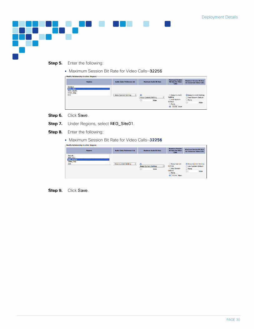
Enter the following:
Maximum Session Bit Rate for Video Calls—
Click .
Under Regions, select .
Enter the following:
Maximum Session Bit Rate for Video Calls—
Click .

Deployment Details
PAGE 31
Configure device pool in CUCM for video and add the video region
Navigate to and click .
Enter the following into the relevant fields, leaving the other fields at their default values:
Device Pool Name—
Date/Time Group—
Region—
Click .
Select the above device pool for all video endpoints
Navigate to , click , and select the video endpoint.
In Device Pool, select
Click .
Click .

Deployment Details
PAGE 32
1. Configure Expressway-C for Mobile and Remote Access
2. Discover Unified CM and IM&P server on Expressway-C
3. Configure Expressway-E for Unified CM
4. Configure server certificates and CA certificates on the Expressway-C
5. Configure server certificates and CA certificates on the Expressway-E
6. Configure Unified Communications traversal zone on Expressway-C
7. Configure credentials on Expressway-E
8. Configure traversal server zone on Expressway-E
Configure Expressway-C for Mobile and Remote access
Navigate to and set
to .
Click .
Navigate to and click .
Enter the following values in the relevant fields:
Domain name—
SIP registrations and provisioning on Unified CM—
IM and Presence services on Unified CM—

Deployment Details
PAGE 33
Click .
Discover Unified CM and IM&P server on Expressway-C
Navigate to , and then click
.
Enter the following values in the relevant fields:
Unified CM publisher address—
Username—
Password
TLS verify mode—

Deployment Details
PAGE 34
Click .
Navigate to , and
then click .
Enter the following values in the relevant fields:
IM and Presence publisher address—
Username—
Password—
TLS verify mode—
Click
Tech Tip
1The TLS verify mode can be turned on if we provide in the address field FQDN names of CUCM and
CUCM IM&P respectively. In addition, the tomcat certificates of the both servers needs to be trusted by
the Expressway-C

Deployment Details
PAGE 35
Configure Expressway-E for Mobile and Remote access
Navigate to , and then set
to .
Click .
Configure server certificates and CA certificates on the Expressway-C
To generate a CSR, navigate to
Next, click
◦ Key length ( in bits)-
◦ Digest Algorthm -
◦ Country-
◦ State or province -
◦ Locality (town name)-
◦ Organization (Company name)-
◦ Organizational unit-

Deployment Details
PAGE 36
Then Click . Once the certificate is generated, download the .PEM file,
rename the file to the .cer format if required and get it signed by your private CA.
Next, obtain your private root Certificate Authority (CA) certificates and public root CA
certificates uesd to sign your Expressway-C and Expressway-E respectively. These needs
to be uploaded on to the Expressway-C, navigate to
Next, navigate to > > . Click on the
choose file and select the signed certificate to be uploaded in step 2. Then click the Upload
New Certificate to upload the new server certificate.

Deployment Details
PAGE 37
Configure server certificates and CA certificates on the Expressway-E
Remote and mobile clients must verify (by validating the server certificate) the identity of the Expressway-
E to which they are connecting. To do this, in their list of trusted CAs, the clients must have the certificate
authority that was used to sign the Expressway-E’s server certificate.
This design requires secure communications between Expressway-C and Expressway-E, as well as
between Expressway-E and endpoints located outside the enterprise.
To generate a CSR, navigate to ,
fill the below fields leaving other at default. Next, click .
◦ Unified CM registrations domains-
◦ Key length ( in bits)-
◦ Digest Algorthm-
◦ Country-
◦ State or province-
◦ Locality (town name)-
◦ Organization (Company name)-
◦ Organizational unit-

Deployment Details
PAGE 38
Once the certificate request is generated via the Generate CSR, download the .PEM file to
be sent for signing to the public CA..
Next, obtain your private root Certificate Authority (CA) certificates and public root CA
certificates uesd to sign your Expressway-C and Expressway-E respectively. Both needs
to be uploaded on to the Expressway-E as well, navigate to

Deployment Details
PAGE 39
Next, navigate to > > . Click on the
choose file and select the server certificate signed by the public CA to be uploaded. Then
click on the .
Configure Unified Communications traversal zone on Expressway-C
Navigate to and click .
Enter the following into the relevant fields, leaving the other fields at their default values:
Under Configuration:
◦ Name—
◦ Type—
Under Connection credentials:
◦ Username—
◦ Password—
Under SIP:
◦ Port—
◦ Accept proxied registrations—
◦ Mobile and remote access—
◦ ICE support—
◦ Poison mode—
Under Location:
◦ Peer 1 address—
Tech Tip
The FQDN in the peer address should resolve to the Expressway-E NAT public IP address to engage
NAT reflection. Hence the DNS used by Expressway-C should resolve the Expressway-E hostname to
Expressaway-E NAT IP address

Deployment Details
PAGE 40
Click Create zone.
Configure the credentials on Expressway-E
Navigate to and click .
Enter the following values in the relevant fields:

Deployment Details
PAGE 41
Name—
Password—
Click .
Configure traversal server zone on Expressway-E
Navigate to and click .
Enter the following into the relevant fields, leaving the other fields at their default values:
Under Configuration section
◦ Name—
◦ Type—
Under Connection credentials
◦ Username—
Under SIP section
◦ Port—
◦ Accept Proxied Registrations—
◦ TLS verify subject name—
◦ ICE support—
◦ Poison mode—

Deployment Details
PAGE 42
Click .
Mobile and remote access is now configured. You can now go to Expressway –C and Expressway –E web
interface and check under the > > to confirm the traversal link is
establsihed and all services have been configured
Expressway-C Unified Communication status

Deployment Details
PAGE 43
Expressway-E Unified Communication status
Deployment Details
PAGE 44
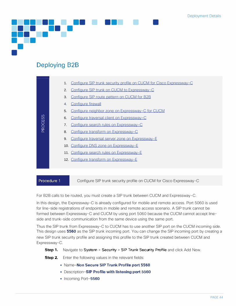
1. Configure SIP trunk security profile on CUCM for Cisco Expressway-C
2. Configure SIP trunk on CUCM to Expressway-C
3. Configure SIP route pattern on CUCM for B2B
4. Configure firewall
5. Configure neighbor zone on Expressway-C for CUCM
6. Configure traversal client on Expressway-C
7. Configure search rules on Expressway-C
8. Configure transform on Expressway-C
9. Configure traversal server zone on Expressway-E
10. Configure DNS zone on Expressway-E
11. Configure search rules on Expressway-E
12. Configure transform on Expressway-E
Configure SIP trunk security profile on CUCM for Cisco Expressway-C
For B2B calls to be routed, you must create a SIP trunk between CUCM and Expressway-C.
In this design, the Expressway-C is already configured for mobile and remote access. Port 5060 is used
for line-side registrations of endpoints in mobile and remote access scenario. A SIP trunk cannot be
formed between Expressway-C and CUCM by using port 5060 because the CUCM cannot accept line-
side and trunk-side communication from the same device using the same port.
Thus the SIP trunk from Expressway-C to CUCM has to use another SIP port on the CUCM incoming side.
This design uses as the SIP trunk incoming port. You can change the SIP incoming port by creating a
new SIP trunk security profile and assigning this profile to the SIP trunk created between CUCM and
Expressway-C.
Navigate to > > and click Add New.
Enter the following values in the relevant fields:
Name—
Description—
Incoming Port—

Deployment Details
PAGE 45
Accept presence subscription—
Accept out-of-dialog refer—
Accept unsolicited notification—
Accept replaces header—
Click .
Configure SIP trunk on CUCM to Cisco Expressway-C
Navigate to and click .
Enter the following into the relevant fields:
Trunk Type—
Device Protocol—
Trunk Service Type—

Deployment Details
PAGE 46
Click .
Enter the following into the relevant fields. Leave the other fields at their default values.
Device Name—
Description—
Device Pool—
Calling and Connected Party Info Format—
Destination Address—
Destination port
SIP Trunk Security Profile—
SIP Profile—
DTMF Signaling Method—
Normalization Script—
Deployment Details
PAGE 47
Click .
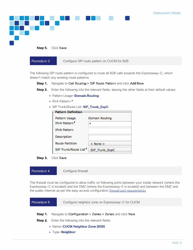
Configure SIP route pattern on CUCM for B2B
The following SIP route pattern is configured to route all B2B calls towards the Expressway-C, which
doesn’t match any existing route patterns.
Navigate to and click .
Enter the following into the relevant fields, leaving the other fields at their default values:
Pattern Usage—
IPv4 Pattern—
SIP Trunk/Route List—
Click .
Configure firewall
The firewall must be configured to allow traffic on following ports between your inside network (where the
Expressway-C is located) and the DMZ (where the Expressway-E is located) and between the DMZ and
the public Internet as per the easy access configuration firewall port requirements
Configure neighbor zone on Expressway-C for CUCM
Navigate to and click .
Enter the following into the relevant fields:
Name—
Type—

Deployment Details
PAGE 48
H.323 Mode—
SIP Mode—
Port—
Transport—
Peer 1 Address—
Peer 2 Address—
Zone Profile—

Deployment Details
PAGE 49
Click .
Configure traversal client zone on Expressway-C
Navigate to , and then click .
Enter the following into the relevant fields, leaving the other fields at their default values:
Name—
Type—
Username—
Password—
H.323 Port—
SIP Port—
Transport—
Peer 1 Address—

Deployment Details
PAGE 50

Deployment Details
PAGE 51
Click .
Configure search rules on Expressway-C
Navigate to , and click .
Enter the following into the relevant fields, leaving the other fields at their default values:
Rule Name—Outbound

Deployment Details
PAGE 52
Description—Outbound
Priority—
Mode—
Pattern type—
Pattern String
Pattern Behavior—
On Successful Match—
Target—
State—
Click .
Click .
Enter the following into the relevant fields, leaving other fields at their default values:
Rule Name—Inbound
Description—Inbound
Priority—
Mode—
Pattern type—
Pattern String
Pattern Behavior—
Replace String
On Successful Match—
Target—
State—
Click .
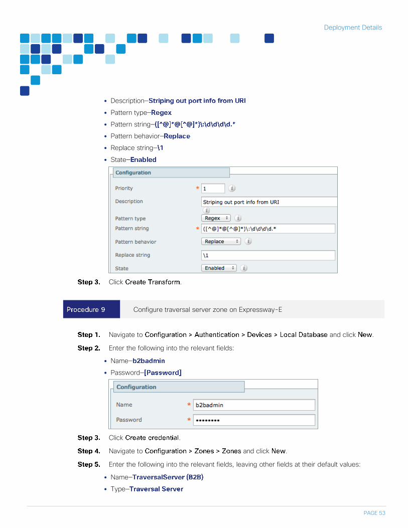
Configure transform on Expressway-C
Navigate to and click .
Enter the following into the relevant fields:
Priority—
Deployment Details
PAGE 53
Description—
Pattern type—
Pattern string—
Pattern behavior—
Replace string—
State—
Click .
Configure traversal server zone on Expressway-E
Navigate to and click .
Enter the following into the relevant fields:
Name—
Password—
Click .
Navigate to and click .
Enter the following into the relevant fields, leaving other fields at their default values:
Name—
Type—

Deployment Details
PAGE 54
Username—
H.323 Port—
SIP Port—
Mobile and remote access—
Transport—
Click .

Deployment Details
PAGE 55
Configure DNS zone on Expressway-E
For a B2B call, the Expressway-E doesn’t need to have established peering relationships with remote
domains. Rather, the Expressway-E routes calls to remote domains via information discovered in public
DNS. Using DNS enables open video federation.
Navigate to and click .
Enter the following into the relevant fields, leaving other fields at their default values:
Name—
Type—
H.323 Mode—
SIP Mode—
Fallback Transport Protocol—
Click .

Deployment Details
PAGE 56
Configure search rules on Expressway-E
Navigate to , and click .
Enter the following into the relevant fields, leaving other fields at their default values:
Rule Name— Outbound
Description
Priority—
Mode—
Pattern type—
Pattern String
Pattern Behavior—
On Successful Match—
Target—
State—
Click Create Search Rule.
Click New.
Enter the following into the relevant fields, leaving other fields at their default values:
Rule Name— Inbound
Description—Inbound
Priority—
Mode—
Pattern type—
Pattern String
Pattern Behavior—
Replace String—
On Successful Match—
Target—
State—
Click .

Deployment Details
PAGE 57
Configure transform on Expressway-E
Navigate to and click .
Enter the following into the relevant fields:
Priority—
Description—
Pattern type—
Pattern string—
Pattern behavior—
Replace string—
State—
Click .
Deployment Details
PAGE 58
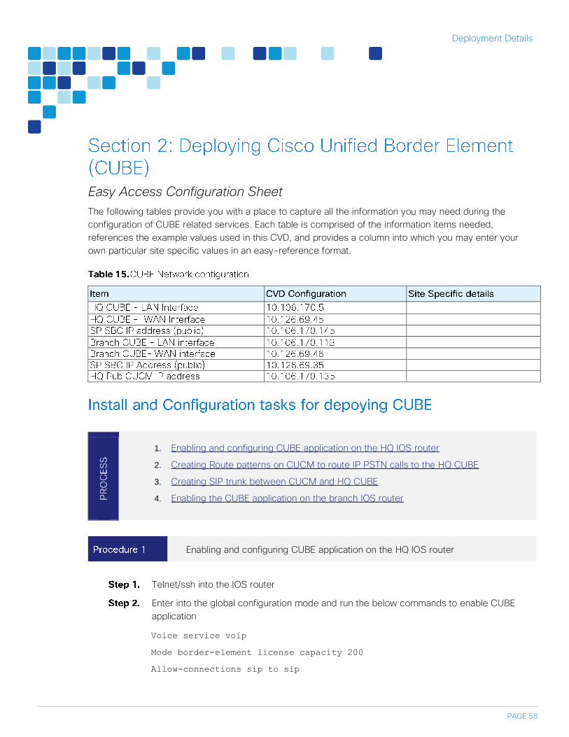
Easy Access Configuration Sheet
The following tables provide you with a place to capture all the information you may need during the
configuration of CUBE related services. Each table is comprised of the information items needed,
references the example values used in this CVD, and provides a column into which you may enter your
own particular site specific values in an easy-reference format.
1. Enabling and configuring CUBE application on the HQ IOS router
2. Creating Route patterns on CUCM to route IP PSTN calls to the HQ CUBE
3. Creating SIP trunk between CUCM and HQ CUBE
4. Enabling the CUBE application on the branch IOS router
Enabling and configuring CUBE application on the HQ IOS router
Telnet/ssh into the IOS router
Enter into the global configuration mode and run the below commands to enable CUBE
application
Voice service voip
Mode border-element license capacity 200
Allow-connections sip to sip

Deployment Details
PAGE 59
Configure other global settings to meet Service Provider requirement as below
Voice service voip
Sip
Early-offer forced
Header-passing
Error-passthru
Enable the topology hiding on the CUBE
Voice service voip
address-hiding
Configure IOS dial-peers on the HQ CUBE for call routing
voice class uri 1 sip
host ipv4:10.106.170.135
voice class uri 2 sip
host ipv4:10.106.170.145
voice class e164-pattern-map 1
e164 9011T
e164 91[2-9]..[2-9]......
e164 9[2-9]......
e164 [2-9]......
dial-peer voice 100 voip
description ***CUCM to HQ CUBE***
incoming uri via 1
session protocol sipv2
codec g711ulaw
dtmf-relay rtp-nte
dial-peer voice 101 voip
description ***HQ CUBE to CUCM***
destination-pattern [2-9]………
session protocol sipv2

Deployment Details
PAGE 60
session target ipv4:10.106.170.135
codec g711ulaw
dtmf-relay rtp-nte
dial-peer voice 102 voip
description ***Service provider to HQ CUBE***
incoming uri via 2
session protocol sipv2
codec g711ulaw
dtmf-relay rtp-nte
dial-peer voice 155 voip
description ***HQ CUBE to Service Provider***
translation-profile outgoing digitstrip
session protocol sipv2
session target ipv4:10.106.170.145
destination e164-pattern-map 1
codec g711ulaw
dtmf-relay rtp-nte
Configure the voice translation rules to strip of the access code 9
voice translation-rule 100
rule 1 /^9\(.*\)/ /\1/
Configure voice translation profile to associate translation rule created in
voice translation-profile digitstrip
translate called 100
Creating Route patterns on CUCM to route IP PSTN calls to the HQ CUBE
For creating route pattern on CUCM please refer to the document Unified Communication for BE6K
technology design guide.

Deployment Details
PAGE 61
Creating SIP trunk between CUCM and HQ CUBE
After logging into the web administration of the CUCM navigate to the
Menu and then click
On the trunk configuration page enter the following details
Trunk Type—
Device protocol—
Trunk Service type—
On the next page, in the Device information section, enter the following details
Device Name—
Description—
Devicepool—
Call Classification—
Location—
Next, in the , enter the following values and then click
Destination Address 1—
Destination port—
Sip Trunk Security Profile—
SIP Profile—

Deployment Details
PAGE 62
In the message window click
On the page, click
On page, click Reset and then click
Enabling the CUBE application on the branch IOS router
Reader Tip
In branch router where CUBE is enabled, recommendation is to have a dedicated MPLS circuit to the
local service provider. Hence, in which case IP addressing scheme might change if we choose to
connect to a different service provider. So it might be required to use a second interface on branch
router to establish the IP PSTN link.
telnet/ssh into the branch IOS gateway
telnet 10.106.170.113 / ssh 10.106.170.113
Enter into the global configuration mode to enable the application
Voice service voip
Mode border-element license capacity 50
Allow-connections sip to sip
Enable address hiding on the CUBE
Voice service voip
Address-hiding
Configure the
voice class uri 2 sip
host ipv4:10.126.69.35
voice class e164-pattern-map 1
e164 9011T
e164 91[2-9]..[2-9]......
e164 9[2-9]......
e164 [2-9]......
dial-peer voice 2102 voip

Deployment Details
PAGE 63
description ***Service Provider to Branch CUBE***
incoming uri via 2
session protocol sipv2
codec g711ulaw
dtmf-relay rtp-nte
dial-peer voice 2155 voip
description ***Branch CUBE to Service provider***
translation-profile outgoing digitstrip
session protocol sipv2
session target ipv4:10.126.69.35
destination e164-pattern-map 1
codec g711ulaw
dtmf-relay rtp-nte
Reader Tip
The dial plan configuration shown here aligns with the UC CVD. CUCC was used to configure dial plans
on the CUCM which by default configures North American Numbering Plan (NANP). However, you can
modify your dial plans to meet your specific needs.
i Tech Tip
There can be SIP trunking to more than one service provider either for load balancing or as alternate
routing option. For SRST configuration please refer the Unified Communications using the BE6K
tehcnology design guide:
http://www.cisco.com/c/en/us/solutions/enterprise/validated-designs-collaboration/index.html
i Tech Tip
The branch might also consider to have a back up E1/T1 PSTN in case of WAN failure or access to
emergency services.

Appendix A: Product List
PAGE 64
Feedback
Please send comments and suggestions about this guide to
Printed in USA CXX-XXXXXX-XX 09/15