2011 annual reporting manual resource module
TRANSCRIPT
Selection of our books indexed in the Book Citation Index
in Web of Science™ Core Collection (BKCI)
Interested in publishing with us? Contact [email protected]
Numbers displayed above are based on latest data collected.
For more information visit www.intechopen.com
Open access books available
Countries delivered to Contributors from top 500 universities
International authors and editors
Our authors are among the
most cited scientists
Downloads
We are IntechOpen,the world’s leading publisher of
Open Access booksBuilt by scientists, for scientists
12.2%
116,000 120M
TOP 1%154
3,800

Chapter 8
© 2012 Toledo Torres and Rosales Huerta, licensee InTech. This is an open access chapter distributed under the terms of the Creative Commons Attribution License (http://creativecommons.org/licenses/by/3.0), which permits unrestricted use, distribution, and reproduction in any medium, provided the original work is properly cited.
Hybrid Filtration Combustion
Mario Toledo Torres and Carlos Rosales Huerta
Additional information is available at the end of the chapter
http://dx.doi.org/10.5772/50353
1. Introduction
Recent stringent emission regulations and depletion of energy sources have imposed special
requirements on combustion technologies for the new millennium. By now it is well known
that hydrocarbon sources, the bedrock of economic wealth and combustion science, are
being depleted 100 000 times faster than they are being replenished. These factors will no
doubt demand the development of novel combustion techniques. Among other concepts,
combustion in a porous media offers a possible technological breakthrough and solutions
for the near and long term. It can provide the basis for development for new combustion
systems. The study of porous media phenomena itself can be a multidisciplinary field
ranging from mechanical and chemical to geological and petroleum applications [1].
Porous media combustion, also known as filtration combustion, is defined as the process in
which a self-sustaining exothermal reactive wave propagates over a porous reagent by
means of gaseous oxidizer filtration through an inert solid matrix towards the reaction zone.
As an internally self-organized process of heat recuperation, filtration combustion of
gaseous mixtures in porous media differs significantly from the homogeneous flames. This
difference is attributed to the following main factors: the highly developed inner surface of
the porous medium results in efficient heat transfer between gas and solid; dispersion of the
gas flowing through a porous media increases effective diffusion and heat transfer in the gas
phase. To further elaborate, once a gas mixture is ignited inside the media, the heat release
from the intense reaction zone is transferred to the solid matrix that subsequently feeds a
fraction of the energy to the solid layers immediately above and below. This process
facilitates a combustion process that ensures stability in a wide range of gas filtration
velocities, equivalence ratios, and power loads.
Stationary and transient systems are the two major design approaches commonly employed
in porous combustion [2-8]. The first approach is widely used in radiant burners and surface
combustor-heaters where the combustion zone is stabilized within the finite element of the
porous matrix. The second (transient) approach involves a traveling wave representing an

Hydrogen Energy – Challenges and Perspectives 202
unsteady combustion zone freely propagating in either downstream or upstream direction
in the inert porous media (IPM). Strong interstitial heat transfer results in a low degree of
thermal non-equilibrium between gas and solid. These conditions correspond to the low-
velocity regime of filtration gas combustion, according to classification given by Babkin [9].
The relative displacement of the combustion zone results in positive or negative enthalpy
fluxes between the reacting gas and the solid matrix. As a result, observed combustion
temperatures can be significantly different from the adiabatic predictions and are controlled
mainly by the reaction chemistry and heat transfer mechanism. The upstream wave
propagation, countercurrent to filtration velocity, results in under-adiabatic combustion
temperatures, while the downstream propagation of the wave leads to the combustion in a
super-adiabatic regime with temperatures much in excess of the adiabatic one. Super-
adiabatic combustion significantly extends conventional flammability limits to the region of
ultra-low heat content mixtures.
Superadiabatic filtration combustion of rich and ultra-rich mixtures creates a situation in
which partial oxidation and/or thermal cracking of hydrocarbons take place. This
technology for hydrogen or synthesis gas (or syngas, a gas mixture that contains varying
amounts of carbon monoxide and hydrogen) production uses an IPM [10-13]. The fuels used
in porous combustion systems are basically of gaseous form due to fluidity, volumetric
capacity, and shorter mixing length scale [14-21]. Liquid fuel reactors have been developed
and used to a smaller extent [22-30].
According with the theory and technology of filtration combustion and the required new
combustion systems, a new hybrid porous reactor can be developed changing an inert solid
volume fraction by solid fuels. Now the porous medium is composed of uniformly mixed
aleatory solid fuel and inert particles [31]. This change produces hybrid filtration combustion
for simultaneous conversion of solid and gaseous fuels to energy (lean combustion) or
hydrogen and synthesis gas (rich combustion).
As a result of composed porous medium, observed combustion temperatures can be lower
than the IPM values and are controlled mainly by the heterogeneous reaction chemistry and
heat transfer mechanism. Upstream and downstream wave propagations are present in the
hybrid porous reactor. The upstream wave propagation in the composite bed is similar to
the inert bed but the downstream wave propagation show a flat temperature profile with
practically constant temperature along the reactor.
The combustion temperature in composite bed decreases from rich to ultra-rich gas fuel-air
mixtures, and also with the increase of solid fuel volume fraction in porous medium. That
suggests a change of dominant kinetic mechanism and a shift from homogeneous to
heterogeneous chemistry. At high downstream propagation velocities near the
stoichiometric conditions the role of gas phase kinetics is dominant. In these conditions, the
upstream wave propagation suppresses the heterogeneous oxidation processes by the
complete consumption of oxidizer. At higher equivalence ratios, the wave propagation is
slower. This increases the role of heterogeneous kinetics. As a result, the ignition and
combustion temperatures drop. In turn, this affects the wave velocity. The mechanism of
heterogeneous combustion becomes dominant for downstream wave propagation. The

Hybrid Filtration Combustion 203
slowly reacting solid fuel is directly exposed to oxidizer. The ignition initiated over the solid
phase is further transferred to the gas phase. It is possible to suggest that the structure of the
wave in this case involves a heterogeneous reaction front followed by the gas phase reaction
front. These fronts are followed by a slow endothermic reaction between the formed steam
and solid/gaseous fuels.
The propagation of downstream hybrid combustion waves in the fuel loaded medium has
resulted in wide combustion fronts with superadiabatic combustion temperatures. Due to
the wide flat temperature profiles it has been found impossible to determine the wave
velocity with sufficient accuracy. The flat temperature profile also suggests that the fuel
particles are burning upstream of the front.
The use of rich and ultra-rich mixtures of gas fuel with air hybrid filtration combustion for
hydrogen and syngas production has big potential. Hydrogen and syngas concentration
increases with an increase of equivalence ratio for gas fuel/air mixtures in the inert porous
medium and composite bed. In comparison, more high concentration of hydrogen and
syngas is obtained in the composite porous media. Hydrogen conversion for gas fuel/air
mixtures for hybrid filtration combustion waves is 50% for higher equivalence ratio.
2. Physical and mathematical description of the hybrid process
Lean combustion results in complete burnout of the hydrocarbon fuel, with the formation of
carbon dioxide and water. Thus, both the composition of the final products and the heat
release are well defined. In contrast to the lean case, the partial oxidation products of rich
and ultra-rich waves are not clearly defined. In such a case, fuel is only partially oxidized in
the wave, and the total heat release could be kinetically controlled by the degree of partial
oxidation. As a result, chemical kinetics, heat release, and heat transfer are strongly coupled
in the rich and ultra-rich waves, rendering it a more complicated and challenging
phenomenon than the lean wave.
In the following we describe the governing equations, derived from fundamental principles, as
well as some suitable models and assumptions that allow the formulation of a mathematical
model. Such a model can be tractable by numerical simulation. We consider the bulk volume V
of the bed separated into the volume occupied by the solid particles, Vs, and the volume
occupied by the gas Vg (i.e. V = Vg +Vs). As usual, we define the porosity θ as the fraction of
bulk volume V occupied by the gas: Vg = θ V. The composition of the gas is characterized by
the molar fractions {yj, j = 1,...,NSP of the NSP chemical species in the gas phase. On the other
hand, the solid phase is composed of reacting fuel particles and inert particles. For the sake of
conciseness, in this section we will refer to this solid fuel simply as fuel (it is implicit, by our
definition of hybrid filtration combustion, that some of the species in the gas phase are also
components of a gaseous fuel injected into the porous medium). To specify the composition of
this solid medium we define partial (mass) densities for the fuel and inert gas as
ρ ρ= =;f i
f is s
m m
V V (1)
Hydrogen Energy – Challenges and Perspectives 204
where mf and mi are respectively the mass of fuel and the mass of inert component in a given
volume V. Note that these densities are based on the solid volume, so that mf = ρf θ V, and
similarly for mi. Here and in all this chapter the subscripts (g) refer to the gas phase, (s) to the
solid phase, (f) to the fuel component in the solid, and (i) to the inert component in the solid.
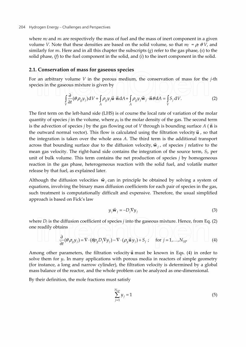
2.1. Conservation of mass for gaseous species
For an arbitrary volume V in the porous medium, the conservation of mass for the j-th
species in the gaseous mixture is given by
θ ρ ρ ρ θ∂
+ ⋅ + ⋅ =∂ ( )d d d d .g j g j g j j j
V A A V
y V y A y A S Vt
u n w n
(2)
The first term on the left-hand side (LHS) is of course the local rate of variation of the molar
quantity of species j in the volume, where ρg is the molar density of the gas. The second term
is the advection of species j by the gas flowing out of V through is bounding surface A ( n
is
the outward normal vector). This flow is calculated using the filtration velocity u
, so that
the integration is taken over the whole area A. The third term is the additional transport
across that bounding surface due to the diffusion velocity, jw
, of species j relative to the
mean gas velocity. The right-hand side contains the integration of the source term, Sj, per
unit of bulk volume. This term contains the net production of species j by homogeneous
reaction in the gas phase, heterogeneous reaction with the solid fuel, and volatile matter
release by that fuel, as explained later.
Although the diffusion velocities jw
can in principle be obtained by solving a system of
equations, involving the binary mass diffusion coefficients for each pair of species in the gas,
such treatment is computationally difficult and expensive. Therefore, the usual simplified
approach is based on Fick’s law
= − ∇j j j jy D yw
(3)
where Dj is the diffusion coefficient of species j into the gaseous mixture. Hence, from Eq. (2)
one readily obtains
θ ρ θρ ρ∂
= ∇ ⋅ ∇ − ∇ ⋅ + =∂
( ) ( ) ( ) ; for 1, ,g j g j j g j j SPy D y y S j Nt
u
(4)
Among other parameters, the filtration velocity u
must be known in Eqs. (4) in order to
solve them for yj. In many applications with porous media in reactors of simple geometry
(for instance, a long and narrow cylinder), the filtration velocity is determined by a global
mass balance of the reactor, and the whole problem can be analyzed as one-dimensional.
By their definition, the mole fractions must satisfy
=
=1
1SPN
jj
y (5)

Hybrid Filtration Combustion 205
so that, one of the NSP equations (4) can be eliminated, and the associated mole fraction can
be obtained by difference from Eq. (5). We remark that, as shown in Ref. [32], solving (NSP –
1) species equations in this way can produce numerical problems, when the exact diffusion
velocities have been substituted by Fick’s law, conducing to a violation in global mass
conservation. The error vanishes when all diffusion coefficients are equal (Dj = D), and it is
negligible if the species for which the equation was removed has a relatively high
concentration in the mixture.
The gas volume Vg in the region V receives chemical species which come from: (i) advection
by the gas flowing into Vg, (ii) enter Vg as a component of volatiles evolved from the solid
fuel, or (iii) enter Vg as a product of heterogeneous reactions of the solid fuel with gaseous
species. The species will react in the gaseous phase according to a homogeneous reaction
mechanism. The presence of heterogeneous reactions means that simultaneously some of
these species will be consumed in such reaction. The superposition of these processes
determine the net source term Sj in the equation (4).
2.1.1. Homogeneous reaction
The homogenous reaction of the NSP species in the gas is generally expressed as a system of
NHO reactions
α αη η α= =
′ ′′←⎯→ = 1 1
M M ; for 1, ,SP SPN N
j j j j HOj j
N (6)
where Mj represents symbolically the molecule of species j, and α αη η′ ′′( , )j j are the
stoichiometric coefficients of the j-th species in the α-th homogeneous reaction. These
reactions are considered, in principle, reversible so that the rates of consumption and
production of species j are given by
α α α α α α α αα α
η η η η= =
′ ′′ ′′ ′+ + 1 1
andHO HON N
j f j b j f j br r r r
respectively. Here, rfα is the forward reaction rate (→), and similarly rbα is the backward
reaction rate (←). Thus, the net production for the j-th species by the homogeneous reaction
mechanism is
α α α αα
η η=
′′ ′= − −,1
( )( )HON
j HO j j f bS r r (7)
The forward and backward reaction rates can be obtained from the law of mass action.
Considering the mechanism (6) as composed of elementary reactions, the order of the
reactions corresponds to the stoichiometric coefficients, and therefore
ααη
α α α αρ η′′
==
′ ′= = ∏11
; withSP SP
j
N Nn
f f g jjjj
r k y n (8)

Hydrogen Energy – Challenges and Perspectives 206
and
ααη
α α α αρ η′′′′
==
′′ ′′= = ∏11
; withSP SP
j
N Nn
b b g jjjj
r k y n (9)
In these expressions, kfα and kbα correspond to the forward and backward kinetic factors,
which are usually modelled using the Arrhenius law
αα
α α
= −
expfb
f f gg
Ek A T
RT (10)
where the constants Afαand bα , as well as the activation energy Efα, are data to be provided
for each reaction. These parameters constitute an essential part of the chemical reaction
model (and one of the most difficult to obtain). The backward kinetic factors are computed
from the forward factors using the equilibrium constants Kα of the reactions
α α
αα α α α
α
η η
′′ ′−
=
′ ′′ = = −
1
with exp ( )SP
n n oNf jo
b j jg gj
k gpk K
K RT RT (11)
where po is the pressure of the standard state (po = 1 bar), R is the universal gas constant and
gj is the Gibbs free energy of species j (gj = hj - Tsj). These properties depend on gas
temperature, and can be obtained from available regression functions, which can be written
as polynomials in Tg such as
=
= 0
mn
j nj gn
h a T (12)
for the enthalpy, and as
−
=
= +1
0
lnm
nj nj g m g
n
s b T b T (13)
for the entropy (as, for example, NASA polynomials).
2.1.2. Volatiles release
The process of volatiles release from the solid fuel, by thermal decomposition and pyrolysis, can
be modelled as one or several irreversible reactions, which we can represent symbolically as
µ µ
µ µ
µ µ
⎯⎯⎯→ + −
⎯⎯⎯→ + −
⎯⎯⎯→ + −
( )1
( )2
( )
1 1 1 1
2 2 2 2
{Fuel} V (1 )S
{Fuel} V (1 )S
{Fuel} V (1 )S
v
v
vNv
v v v v
k
k
kN N N N
(14)

Hybrid Filtration Combustion 207
to indicate the conversion of the solid fuel into volatiles {V1, V2, … ,VNv},all of which have a
prescribed chemical composition. The constants {μβ, β= 1, … , Nv}, which are also parameters
of the model, denote the fraction of fuel mass that is transformed into the volatile Vβ via the
β-th reaction in the system (14). Such transformation leaves a solid substance Sβ which will
react heterogeneously with the surrounding gas (as, for example, coke when coal is being
burned). For each of these Nv reactions, the model postulates a kinetic factor that can be put
into an Arrhenius form
β βββ β
= − =
( ) exp for 1,...,bvs v
s
Tk A T N
T (15)
as a function of the solid particles temperature Ts. These factors are defined such that for a
given mass of fuel mf, the rate at which mass of volatile Vβ is released into the gas phase is
given by
ββ β µ=( ) ( )v vfr k m (16)
The model requires the activation temperatures Tβ, the pre-exponential constants, and the
composition of the released volatiles. Typically for coal, the species present in the volatiles
are H2, H2O, CO, CO2, CH4 and some other hydrocarbons. The composition can be defined in
terms of the mass fraction of the species present in such gaseous mixtures. We use σjβ to
indicate the mass fraction of species j in the volatile β. Therefore, superposing the effects of the
Nv vias of volatilization, the source of species j in the gas phase, per unit of bulk volume, is
β βββ
θ ρµ σ
=
−= ( )
,1
(1 ) vNf v
j v jj
S kW
(17)
due to the volatilization process. Wj is the molecular weight of species j and ρ f is defined in
Eq.(1).
2.1.3. Heterogeneous reaction
The solid substances Sβ left by the volatilization mechanism can further react with several
species from the surrounding gas. This heterogeneous reactions can be treated in a similar
way to what is done in 2.1.1 for the homogeneous reactions. First, we need to define
precisely the solids Sβ. When the solid fuel is coal, the usual assumption is to consider Sβ as
pure carbon for all the volatilization reactions (14). Global heterogeneous reactions that can
take place in such conditions are for example
+ ⎯⎯→
+ ⎯⎯→
+ ⎯⎯→
+ ⎯⎯→ +
2
2 2
2
2 2
2C O 2CO
C O CO
C CO 2CO
C H O CO H
(18)

Hydrogen Energy – Challenges and Perspectives 208
For some other fuels, whose fixed carbon fraction is mostly C, such as wood pellets, the
treatment of Sβ as C could also be a good approximation. Alternatively, a more accurate
representation of Sβ could be a pseudo-molecule CxHy, that can be used to represent coke or
other form of carbonized material. Since we want to consider the solid fuel as just one
component of the solid phase, in addition to the inert material, the heterogeneous reactions
cannot discriminate between different solid species, and therefore the heterogeneous
reaction mechanism must be written as
γ γν ν= =
′ ′′+ ⎯⎯→ = 1 1
S M M for 1SP SPN N
j j j j HEj j
γ , ,N (19)
where NHE is the number of reactions in the heterogeneous mechanism and S denotes the
molecular formulae for the solid material left by the pyrolysis (C or CxHy). As before, Mj
stands for the molecule of j-th species in the gas phase, and the constants γ γν ν′ ′′( , )j j are the
stoichiometric coefficients for the j-th species in the γ-th heterogeneous reaction. A more
general treatment would be to consider different solid species Sβ generated by the
volatilization reactions. In that case, different S molecules could appear for different γ in the
equations (19). The model for the kinetics could be essentially the same than the one shown
below, but such an approach would require to characterize the solid phase by the content of
inert material and more than one solid fuel species: ρi, ρS1, ρS2,..., instead of ρi and ρf.
Consequently, that would demand to solve mass conservation equations for ρS1, ρS2,...,
instead of just one for ρf (See 2.2). Although in conceptual terms there is no more complexity
in such a procedure, we prefer do not follow that line here, in order to avoid the
introduction of too many parameters, which are currently difficult to obtain and validate.
The mass rate of consumption, per unit of bulk volume, through the γ-th reaction of the fuel
that has remained solid (in the S form), can be formulated as
ν
γ γ ρ ω′
=
= −∏( )( )
1
( ) (1 )SP
j
NHH
g jfj
r k y F (20)
where ω and F are defined below, and γ( )Hfk is a kinetic factor defined such that when
multiplied by the product of the concentrations in Eq.(20), gives the rate of mass
consumption per unit area of solid fuel. This kinetic energy can be postulated to follow as
usual an empirical Arrhenius law
γ γγγ
= −
( )( ) ( ) exp
HbH Hsf
s
Ek A T
RT (21)
for which the activation energy Eγ and pre-exponential constants must be provided. The last
two factors in Eq. (20) takes into account the surface area of solid fuel per unit of bulk
volume. F is the ratio of particles surface area to the volume of porous medium. For a
homogeneous porous medium with particles of characteristic mean size d, it has the value

Hybrid Filtration Combustion 209
θ−
=6(1 )
Fd
(22)
The factor (1-ω) is the fraction of F that corresponds to solid fuel area. The variable ω can be
defined as the degree of fuel burnout, since ω = 1 corresponds to the state when all the fuel
that remained in the solid phase has been consumed. The minimum value for ω depends on
the initial fraction of fuel in the porous medium (see 2.2).
Taking into account the production and consumption of gaseous species by the reactions
(19), the net production of species j by the whole heterogeneous reactions mechanism is
then
γ γ γγ
ν ν=
′′ ′= − ( ),
S 1
1( )
HENH
j HE j jS rW
(23)
where WS is the molecular weight of S. We have taken reactions (19) as irreversible, but if
there were reversible reactions among them, the treatment can be done in the same way as
in subsection 2.1.1, applying the equilibrium constants to obtain backward reaction rates
that should be subtracted from γ( )Hr in Eq. (23).
In summary, the species mass conservation equations can be written more explicitly as
θ ρ θρ ρ∂
= ∇ ⋅ ∇ − ∇ ⋅ + + + =∂ , , ,( ) ( ) ( ) ; for 1, ,g j g j j g j j HO j v j HE SPy D y y S S S j Nt
u
(24)
where the net sources of species j by homogeneous reactions, volatilization and
heterogeneous reactions are given by Eqs. (7), (17) and (23), respectively.
2.2. Conservation of mass for solid fuel
To derive an equation expressing the mass conservation of solid fuel we consider first a
region of volume V(t), in the burning porous medium, whose boundary surface moves with
the local velocity v
at which the solid fuel combustion propagates. In that situation the mass
conservation of fuel is given by
ρ θ− = − ( ) ( )
d(1 )d d
df f
V t V t
V B Vt
(25)
where Bf is the rate of mass fuel consumption, per unit volume, by heterogeneous reaction
and volatilization. The derivative on the LHS of Eq. (25) gives
ρ θ ρ θ∂
− + − ⋅ = −∂
( ) ( ) ( )
[ (1 )]d (1 ) d df f f
V t A t V t
V A B Vt
v n
(26)
whence the governing equation for the partial density of fuel in the solid phase becomes

Hydrogen Energy – Challenges and Perspectives 210
ρ θ ρ θ∂
− + ∇ ⋅ − = −∂
[ (1 )] [ (1 ) ]f f fBt
v
(27)
The loss of mass of fuel by volatilization is given by the summation of the Sj,v terms in Eq.
(17), for all the species. On the other hand, the loss of fuel mass due to heterogeneous
reactions is given by the summation of all the consumption rates in Eq. (20), for all of such
reactions. Therefore,
γγ
ρ θ ρ θ= =
∂− + ∇ ⋅ − = − −
∂ ( )
,1 1
[ (1 )] [ (1 ) ]SP HEN N
Hf f j v
j
S rt
v
(28)
The evaluation of the rates γ( )Hr requires the degree of fuel burnout ω. Denoting by ρ̂i and
ρ̂ f the intrinsic densities (true densities) of the inert material and the fuel respectively, ω
can be obtained from the relations
ρ ρ ρ ρθ θ
+ = + − − −
ˆ ˆ 1(1 ) (1 )
f ff i f i
V V
V V (29)
and
ω− = =6
(1 )f fA V
FV d V
(30)
where Vf represents the volume occupied by the fuel particles in a given bulk volume V, and
Af represents their surface area. Combining Eqs. (29), (30) and (22) we have
ρ ρ ρ
ωρ ρ
− +=
−
ˆ ( )
ˆ ˆ
f f i
f i
(31)
so that the value of ω, at a given position, can be determined using the instantaneous local
values of ρf and ρi at that position.
2.3. Conservation of energy of the gas phase
For the analysis of energy conservation in the gas, we consider the thermal and the chemical
energies of the gaseous species, and neglect the kinetic energy of the flow. The energy per
mole of gas is then eg = hg - p/ρg , with hg being the total enthalpy per mole of gas mixture
=
= 1
SPN
g j jj
h y h (32)
The enthalpies of the different species (hj) include their enthalpy of formation (and they can
be computed with functions like Eq. (12)). Proceeding similarly to the analysis of mass
conservation, an integral balance of energy in a volume V results in

Hybrid Filtration Combustion 211
θρ ρ θ∂
+ ∇ ⋅ = + ∂ ( ) ( ) d d dg g g g V A
V V A
e e V H V H At
u
(33)
where HV refers to sources of energy per unit of bulk volume, and HA denote energy fluxes
going into the volume across the boundary surface of V, per unit of gas-phase area. We have
also neglected here the work done on the gas by surface forces (such as pressure and viscous
stresses), and body forces (such as gravity). Those mechanical effects on the total energy are
clearly negligible in comparison with the thermal effects.
The fluxes in HA can be joined into a vector q
such that = − ⋅AH q n
, and then Eq. (33) leads
to the differential equation
θρ ρ∂
+ ∇ ⋅ = − ∇ ⋅∂
( ) ( )g g g g Ve e Ht
u q
(34)
Generally, it is preferred to use the enthalpy as the primitive variable for the gas energy
equation. In that case Eq. (34) reads as
θ
θρ ρ∂∂
+ ∇ ⋅ = + ∇ ⋅ + − ∇ ⋅∂ ∂
( )( ) ( ) ( )g g g g V
ph h p H
t tu u q
(35)
The pressure terms appearing in (35) are also associated with mechanical energy of the flow.
They contribute in part to the energy of deformation due to gas expansion (which is stored
in the gas as thermal energy), and also to the flow acceleration due to pressure gradients
(which changes the kinetic energy). As stated above, we consider these mechanical energy
contributions negligible, in comparison with the thermal energy in a reactor. Consequently,
the first two terms on the RHS of Eq. (35) are discarded.
The energy flux vector q
contains the heat diffusion, which can be expressed by Fourier’s
law, and the additional transport of energy due to the diffusion of species, with different
enthalpies, in the multi-component gas
λ ρ λ ρ= =
= − ∇ + = − ∇ − ∇ 1 1
SP SPN N
g g g j j j g g j j jj j
T y h T h D yq w
(36)
In this equation we have introduced again Fick’s law for the diffusion velocities, while λg is
the gas thermal conductivity.
According to the processes described previously, the energy source term HV must contain (i)
HV,v: the enthalpy carried into the gas by the volatiles evolved from the solid fuel, (ii) HV,HE:
the energy released toward the gas by the heterogeneous reactions of the solid fuel and (iii)
HV,Q: the heat transfer from the solid phase (inert material and fuel) to the gas.
With regards to the enthalpy flow contributed by the volatiles, it can be calculated as
=
= , ,1
( )SPN
V v j v j sj
H S h T (37)

Hydrogen Energy – Challenges and Perspectives 212
where the total molar flow of species j carried in the volatiles, Sj,v ,is given by Eq. (17). We
make the assumption that this volatiles gases are released at the temperature Ts of the solid
phase. Note that the solid phase is characterized by a common local temperature as
discussed in subsection 2.4.
The heterogeneous reactions involve the adsorption of gaseous species into the fuel
particles, and the desorption of the reaction products back to the gaseous phase. Using the
heterogeneous reaction model described in sub-section 2.1.3, we have that for the γ-th of
such reactions, the enthalpy transport associated with those adsorbed and desorbed flows
could be in principle estimated as
γ γ
γ γν ν= =
′ ′′ ′′ ( ) ( )
S S1 1
( ) and ( ), respectively.SP SP
H HN N
j j g j jj j
r rh T h T
W W
In the first expression the enthalpies of the incoming species can be evaluated at the
temperature Tg of the gas in the neighborhood of the fuel particle. In the second expression
however the enthalpies of the outgoing products should be evaluated at a temperature ′′Tthat would have to be approximated in some way. Such an estimation is a difficult task, so
that a practical approach is to consider that a fraction ε of the heat reaction is retained in the
solid particle, contributing to its internal energy, while the remaining fraction (1- ε) goes
into the gas phase as the net flow of sensible enthalpy. More explicitly, the heat released by
the γ-th heterogeneous reaction in the solid is
( )γγ γ γ
γ γγ γ γ γ
γ γ
ν ν
ν ν ν ν
=
= = =
′ ′′ ′′= − +
′′ ′ ′ ′′ ′′ = − − + Δ − Δ
( )
S 1
( ) ( )
S S1 1 1
,
( ) ( )
( ) ( ) ( )
SP
SP SP SP
H No
s j j g j j fSj
H HN N No o
j j fj fS j j g j jj j j
R V HE
rQ h T h T h
W
r rh h h T h T
W W
Q H
(38)
with QRγ being the standard heat of reaction and Δhj are sensible enthalpies. On the other
hand, we assume that
γ
γ γε= −( )
S
H
s R
rQ Q
W (39)
(By definition, QRγ is negative for exothermic reactions, whence the minus sign in Eq. (39)).
As a result, the net flow of energy toward the gas phase is
γ γ γγ γ
ε= =
= = − − ( ), ,
S1 1
1(1 )
HE HEN NH
V HE V HE RH H r QW
(40)
We look now to the third component of HV, namely the convective heat transfer to the gas
on the surface of the solid medium. This heat flow can be calculated, in a simplified form, as

Hybrid Filtration Combustion 213
ξ= −, ( )V Q s gH F T T (41)
where ζ is the heat transfer coefficient, which can be estimated from empirical relations for
porous media, as for example [33]
= + 0.6 1/3Nu 2 1.1Re Prg (42)
In this expression the characteristic length for the Reynolds and Nusselt numbers is
taken as two times the particles size d, and the velocity is the effective mean velocity of
the flow:
θ ξ
ν λ
| |= =
2 2Re , Nu
g g
d du
(43)
Upon substituting Eq. (36) into (35), the equation for energy conservation in the gas phase
becomes
θρ ρ θλ θρ=
∂ + ∇ ⋅ = ∇ ⋅ ∇ + ∇ ⋅ ∇ + + + ∂
, , ,1
( ) ( ) ( )SPN
g g g g g g g j j j V v V HE V Qj
h h T h D y H H Ht
u
(44)
Recall that we are using total enthalpies hj, which include the enthalpy of formation, so
that the heat released by the homogeneous reactions in the gaseous phase is implicit in Eq.
(44).
This equation of energy, coupled with the equations for mass conservation of species, and
the equations for the solid phase, give rise to a system of simultaneous partial differential
equations that must be solved by a numerical iterative scheme. In that case Eq. (44) can be
solved for hg as its primitive variable, and the gas temperature can be obtained by solving
the polynomial equation
= =
= = 0 1
withSPNm
nnj g g nj nj j
n j
c T h c a y (45)
in each iteration. This equation for Tg results from Eqs. (32) and (12).
2.4. Conservation of energy of the solid phase
The conservation of energy for the solid phase can be analyzed in the same volume V(t)
used in subsection 2.3, with a boundary that moves at the velocity ( v
) of propagation of
solid fuel consumption. In this way we have
ρ ρ θ+ − = + ( ) ( ) ( )
d( )(1 )d d d
df f i i s s s
V t V t A t
e e V G V H At
(46)
or equivalently
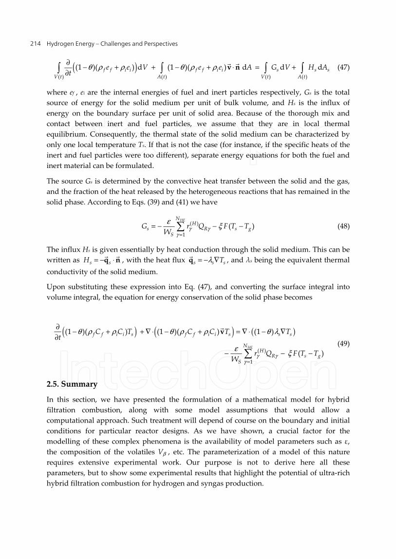
Hydrogen Energy – Challenges and Perspectives 214
( )θ ρ ρ θ ρ ρ∂
− + + − + ⋅ = +∂
( ) ( ) ( ) ( )
(1 )( ) d (1 )( ) d d df f i i f f i i s s s
V t A t V t A t
e e V e e A G V H At
v n
(47)
where ef , ei are the internal energies of fuel and inert particles respectively, Gs is the total
source of energy for the solid medium per unit of bulk volume, and Hs is the influx of
energy on the boundary surface per unit of solid area. Because of the thorough mix and
contact between inert and fuel particles, we assume that they are in local thermal
equilibrium. Consequently, the thermal state of the solid medium can be characterized by
only one local temperature Ts. If that is not the case (for instance, if the specific heats of the
inert and fuel particles were too different), separate energy equations for both the fuel and
inert material can be formulated.
The source Gs is determined by the convective heat transfer between the solid and the gas,
and the fraction of the heat released by the heterogeneous reactions that has remained in the
solid phase. According to Eqs. (39) and (41) we have
γ γγ
εξ
=
= − − − ( )
1
( )HEN
Hs R s g
S
G r Q F T TW
(48)
The influx Hs is given essentially by heat conduction through the solid medium. This can be
written as = − ⋅s sH q n
, with the heat flux λ= − ∇s s sTq
, and λs being the equivalent thermal
conductivity of the solid medium.
Upon substituting these expression into Eq. (47), and converting the surface integral into
volume integral, the equation for energy conservation of the solid phase becomes
( ) ( ) ( )
γ γγ
θ ρ ρ θ ρ ρ θ λ
εξ
=
∂− + + ∇ ⋅ − + = ∇ ⋅ − ∇
∂
− − − ( )
1
(1 )( ) (1 )( ) (1 )
( )HE
f f i i s f f i i s s s
NH
R s gS
C C T C C T Tt
r Q F T TW
v
(49)
2.5. Summary
In this section, we have presented the formulation of a mathematical model for hybrid
filtration combustion, along with some model assumptions that would allow a
computational approach. Such treatment will depend of course on the boundary and initial
conditions for particular reactor designs. As we have shown, a crucial factor for the
modelling of these complex phenomena is the availability of model parameters such as ε, the composition of the volatiles Vβ , etc. The parameterization of a model of this nature
requires extensive experimental work. Our purpose is not to derive here all these
parameters, but to show some experimental results that highlight the potential of ultra-rich
hybrid filtration combustion for hydrogen and syngas production.

Hybrid Filtration Combustion 215
3. Hydrogen production by hybrid filtration combustion
In this section, we show experimental results for wave velocities, combustion temperature,
and H2 and CO concentrations for hybrid combustion of gas and solid fuels in porous
media.
3.1. Natural gas and coal particles
The porous medium is composed of uniformly mixed aleatory coal and alumina spheres
with varying volume fractions. This section provide the data on natural gas-air flames
stabilized inside hybrid porous media with a volumetric coal content from 0 to 75% for an
equivalence ratio φ = 2.3 and a filtration velocity of 15 cm/s.
The solid temperatures recorded for hybrid filtration combustion in coal-alumina beds,
decreased from 1537 K at 15 % of coal in porous media to 1217 K at 75 % (Fig. 1a). The wave
velocity is reduced with increase of coal volume fraction. At high coal contents the wave
velocity is limited by the oxygen availability and the bed displacement resulting from the
coal consumption. The latter factor suggests that the wave velocity in the packed bed with
100% coal content will be close to zero.
The hydrogen concentration increased with an increase of coal content with the maximum
of 22% at a coal content of 75%. The result shows that high combustion temperatures
facilitate hydrogen production in hybrid filtration combustion. The carbon monoxide also
increased with an increase of coal content.
The maximum hydrogen conversion reached 55% at a coal content of 75% compare to 35.1%
for natural gas flames propagating in the inert porous bed (Fig. 1b).
3.2. Butane and wood pellets
The porous media was composed of uniformly mixed aleatory wood pellets and alumina
spheres. The equal volumes of 5.6 mm solid alumina balls and wood pellets were mixed
resulting in the packet bed with a porosity of ~40%. Experimental data were collected for a
slightly increasing filtration velocity in a range of equivalence ratios from stoichiometry (φ =
1.0) to φ = 2.6.
The solid temperature of butane/air mixtures in the inert porous medium increases from
1510 K at φ = 1.45 to 1610 K at φ = 2.6 (Fig. 2a). The solid temperatures recorded for hybrid
filtration combustion in wood pellets-alumina spheres porous media, decrease from 1477
K at φ = 1.45 to 1216 K at φ = 2.6. For butane/air mixtures in the inert and composite
porous media the maximum absolute velocity value of ~0.012 cm/s is observed for φ = 1.45
(Fig. 2b).
Hydrogen concentration increases with an increase of equivalence ratio for butane/air
mixtures in the inert porous medium. In comparison, more than four times higher
concentration of hydrogen is measured for butane/air mixtures in the composite porous

Hydrogen Energy – Challenges and Perspectives 216
media made of alumina and wood pellets. For butane/air mixtures in the inert porous
medium the concentration of carbon monoxide increased with equivalence ratio and for an-
inert porous media the concentration of CO remains almost constant with the equivalence
ratio.
Figure 1. Combustion temperatures and wave velocities (A) and degree of conversion to hydrogen (B)
for rich and ultra-rich waves for natural gas mixtures with air varying the volume of coal in the porous
media from 0 to 75% [34].
The hydrogen yield is calculated using the initial hydrogen content in butane for the case of
inert bed and the initial hydrogen content in butane and wood pellets for the case of the
composite bed. The maximum yield recorded for the inert porous medium is close to 10% at
φ = 2.6 (Fig. 2c). The maximum yield recorded for the composite pellets is ~48% at φ = 2.4.
400
600
800
1000
1200
1400
1600
0
0.005
0.01
0.015
0.02
0.025
0.03
0 10 20 30 40 50 60 70 80
Co
mb
us
tio
n T
em
pe
ratu
re,
K
Co
mb
us
tio
n W
av
e V
elo
cit
y, c
m/s
Coal Content, %
T
u
A
30
35
40
45
50
55
60
0 10 20 30 40 50 60 70 80
Hyd
rog
en
Co
nvers
ion
, %
Coal Content, %
Inert bed
B

Hybrid Filtration Combustion 217
Figure 2. Combustion temperatures (A), wave velocities (B) and degree of conversion to hydrogen (C) for
rich and ultra-rich waves for butane mixtures with air in the inert bed and composite porous media [35].
3.3. Propane and polyethylene pellets
The reactor is filled with a uniformly mixed aleatory polyethylene pellets and alumina
spheres whose diameter is 5.6 mm. The geometry of polyethylene pellets are 2.4x5.0x4.4
1100
1200
1300
1400
1500
1600
1700
1.2 1.4 1.6 1.8 2 2.2 2.4 2.6 2.8
Inert bed
Composite bed
Co
mb
us
tio
n T
em
pe
ratu
re, K
Equivalence Ratio A
-0.012
-0.01
-0.008
-0.006
-0.004
-0.002
0
0.002
0.004
1.2 1.4 1.6 1.8 2 2.2 2.4 2.6 2.8
Inert bedComposite bedC
om
bu
sti
on
Wav
e V
elo
cit
y, cm
/s
Equivalence Ratio B
0
10
20
30
40
50
1.2 1.4 1.6 1.8 2 2.2 2.4 2.6 2.8
Inert bed
Composite bed
[H2]/
[Fu
el]
Co
nvers
ion
, %
Equivalence Ratio C

Hydrogen Energy – Challenges and Perspectives 218
mm. Experimental data were collected at a range of equivalence ratios (φ) from φ =1.0 to φ
=1.7. The air/propane flow rate was maintained constant at 5.7 L/min yielding a filtration
velocity of 11.3 cm/s.
Figure 3. Combustion temperatures (A), wave velocities (B) and hydrogen concentration (C) in rich
mixtures of propane with air for gaseous and hybrid filtration combustion waves.
900
1000
1100
1200
1300
1400
1 1.2 1.4 1.6 1.8
Composite bed
Inert bedC
om
bu
sti
on
Te
mp
era
ture
, K
Equivalence Ratio A
-0.01
-0.008
-0.006
-0.004
-0.002
0
1 1.2 1.4 1.6 1.8
Composite bed
Inert bed
Co
mb
usti
on
Wav
e V
elo
cit
y,
cm
/s
Equivalence Ratio B
0
1
2
3
4
5
6
7
1 1.2 1.4 1.6 1.8
Composite bed
Inert bed
Hyd
rog
en
, %
Equivalence Ratio C
Hybrid Filtration Combustion 219
The solid temperature of propane/air mixtures in the inert porous medium decreases from
1159 K at φ = 1.0 to 987 K at φ = 1.2 (Fig. 3a). Then the temperature increase to 1346 K at φ =
1.7. The solid temperatures recorded for hybrid filtration combustion in polyethylene
pellets-alumina spheres porous media, shows similar behaviour and decrease from 1215 K
at φ = 1.0 to 1070 K at φ = 1.4. Then the temperature increase to 1279 K at φ = 1.7. The
experimental results for propane/air mixtures in the inert and composite porous media
upstream wave were recorded in all the range of equivalence ratios studied (Fig. 3b).
Hydrogen concentration increases with an increase of equivalence ratio for propane/air
mixtures in the inert porous medium and composite porous media made of alumina and
polyethylene pellets. The maximum generated mole fraction of hydrogen is 6.7% for hybrid
propane. Carbon monoxide is also generated in both porous media reactor.
4. Conclusion
In this chapter we have defined the hybrid filtration combustion process. The physical
phenomena involved as well as their mathematical description by the governing equations
enforcing mass and energy conservation for both the gas and solid phases are discussed.
We presented experimental evidence that such a process of hybrid filtration combustion can
actually be achieved in practice. In particular we showed applications for reformation of
gaseous and solid fuels into hydrogen and syngas. This was shown for several combinations
of gaseous and solid fuels.
Author details
Mario Toledo Torres* and Carlos Rosales Huerta
Department of Mechanical Engineering, Technical University Federico Santa Maria, Valparaiso,
Chile
Acknowledgement
The authors wish to acknowledge the support by the CONICYT-Chile (FONDECYT 1121188
and BASAL FB0821 - FB/05MT/11).
5. References
[1] Kaviany M (1995) Principles of heat transfer in a porous media. Springer-Verlag. New
York.
[2] Toledo M, Bubnovich V, Saveliev A, Kennedy L (2009) Hydrogen production in
ultrarich combustion of hydrocarbon fuels in porous media. Int. J. Hydrogen Energy 34:
1818-1827.
* Corresponding Author

Hydrogen Energy – Challenges and Perspectives 220
[3] Dhamrat RS, Ellzey JL (2006) Numerical and experimental study of the conversion of
methane to hydrogen in a porous media reactor. Combust. Flame 144: 698-709.
[4] Babkin V, Korzhavin A, Bunev V (1991) Propagation of premixed gaseous explosion
flames in porous media. Combust. Flame 87: 182-190.
[5] Babkin V. (1993) Filtrational combustion of gases. Present state of affairs and prospects.
Pure Appl. Chem. 65: 335-344.
[6] Vogel BJ, Ellzey JL (2005) Subadiabatic and superadiabatic performance of a two-section
porous burner. Combust. Sci. Technol. 177: 1323-1338.
[7] Abdul M, Abdullaha M, Abu Bakarb M (2009) Combustion in porous media and its
applications - a comprehensive survey. J. Environ. Manage 90: 2287-2312.
[8] Bingue JP, Saveliev AV, Fridman AA, Kennedy LA (2002) Hydrogen production in
ultra-rich filtration combustion of methane and hydrogen sulfide. Int. J. Hydrogen
Energy 27: 643-649.
[9] Babkin V (1993) Filtrational combustion of gases. Pure and Applied Chemistry 65: 335-
344.
[10] Dobrego KV, Zhdanok SA, Khanevich EI (2000) Analytical and experimental
investigation of the transition from low velocity to high-velocity regime of filtration
combustion. Exp. Therm. Fluid. Sci. 21: 9-16.
[11] Foutko SI, Shabunya SI, Zhdanok SA, Kennedy LA (1996) Superadiabatic combustion
wave in a diluted methane–air mixture under filtration in a packed bed. Proc. Combust.
Inst. 25: 1556-65.
[12] Kennedy LA, Bingue JP, Saveliev AV, Fridman AA, Foutko SI (2000) Chemical
structures of methane–air filtration combustion waves for fuel-lean and fuel-rich
conditions. Proc. Combust. Inst. 28: 1431-1438.
[13] Drayton MK, Saveliev AV, Kennedy LA, Fridman AA, Li Y- E (1998) Syngas production
using superadiabatic combustiom of ultra-rich methane-air mixtures. Proc Combust.
Inst. 27: 1361-7.
[14] Weinberg FJ, Bartleet TG, Carleton FB, Rimbotti P, Brophy JH, Manning RP (1988)
Partial oxidation of fuel rich mixtures in a spouted bed combustor. Combust Flame 72:
235-9.
[15] Ytaya Y, Oyashiki T, Hasatani M (2002) Hydrogen production by methane-rich
combustion in a ceramic burner. J. Chem. Eng. Jpn. 35: 46-56.
[16] Kennedy LA, Saveliev AV, Fridman AA (1999) Transient filtration combustion.
Mediterr. Combust. Symp. 1: 105-39.
[17] Kennedy LA, Saveliev AA, Bingue JP, Fridman AA (2002) Filtration combustion of a
methane wave in air for oxygen enriched and oxygen-depleted environments. Proc.
Combust. Inst. 29: 835-41.
[18] Howell JR, Hall MJ, Ellzey JL (1996) Combustion of hydrocarbon fuels within porous
medium. Prog. Energy Combust. Sci. 22: 121-45.

Hybrid Filtration Combustion 221
[19] Gavrilyuk VV, Dmitrienko YM, Zhdanok SA, Minkina VG, Shabunya SI, Yadrevskaya
NL, et al. (2001) Conversion of methane to hydrogen under superadiabatic filtration
combustion. Theor. Found. Chem. Eng. 35: 589-96.
[20] Gerasev AP (2008) Hybrid autowaves in filtration combustion of gases in a catalytic
fixed bed. Combust. Explos. 44: 123-32.
[21] Schoegl I, Newcomb SR, Ellzey JL (2009) Ultra-rich combustion in parallel channels to
produce hydrogen-rich syngas from propane. Int. J. Hydrogen Energy 34: 5152-63.
[22] Dixon MJ, Schoegl I, Hull CB, Ellzey JL (2008) Experimental and numerical conversion
of liquid heptane to syngas through combustion in porous media. Combust. Flame 154:
217-31.
[23] Pedersen-Mjaanes H, Chan L, Mastorakos E (2005) Hydrogen production from rich
combustion in porous media. Int. J. Hydrogen Energy 30: 579-92.
[24] Tarun K. Kayal, Mithiles Chakravarty (2007) Modeling of a conceptual self-sustained
liquid fuel vaporization–combustion system with radiative output using inert porous
media, International Journal of Heat and Mass Transfer 50: 1715–1722.
[25] Sumrerng Jugjai, Nopporn Polmart (2003) Enhancement of evaporation and combustion
of liquid fuels through porous media, Experimental Thermal and Fluid Science 27: 901-
909.
[26] Trimis D, Wawrzinek K, Hatzfeld O, Lucka K, Rutsche A, Haase F, Kruger K, and
Kuchen C (2001) High modulation burner for liquid fuels based on porous media
combustion and cool flame vaporization. Proceedings of the Sixth International
Conference on Technologies and combustion for clean environment, v.2, Porto,
Portugal, 9-12 July (Ed. M. G. Carvhalho), pp. 1-8.
[27] Tarun K. Kayal, Mithiles Chakravarty (2005) Combustion of liquid fuel inside inert
porous media: an analytical approach. International Journal of Heat and Mass Transfer
48 : 331-339.
[28] Haack DP (1993) Mathematical analysis of radiatively enhanced liquid droplet
vaporization and liquid fuel combustion within a porous inert medium. MSc Thesis,
University of Texas, Austin.
[29] Kaplan M and Hall MJ (1995) The combustion of liquid fuels within a porous media
radiant burner. Exp. Thermal. Fluid Sci. 11: 13-20.
[30] Tseng CJ and Howell JR (1994) Liquid fuel combustion within inert porous media. Heat
Trans. Combined Modes, ASME, HTD 299 : 63-69.
[31] Salganskii EA, Fursov VP, Glazov SV, Salganskaya MV, Manelis GB (2006) Model of
vaporeair gasification of a solid fuel in a filtration mode. Combust. Explos. 42: 55-62.
[32] Poinsot T, and Veynante D (2001) Theoretical and Numerical Combustion. R. T.
Edwards Inc. Philadelphia.
[33] Salgansky EA, Kislov VM, Glazov SV, Zholudev AF, Manelis GB (2008) Filtration
Combustion of a Carbon–Inert Material System in the Regime with Superadiabatic
Heating. Combustion, Explosion, and Shock Waves 44: 273-280.

Hydrogen Energy – Challenges and Perspectives 222
[34] Toledo MG, Utria KS, González FA, Zúñiga JP, Saveliev AV (2012) Hybrid filtration
combustion of natural gas and coal. Int. J. Hydrogen Energy 37 : 6942-6948.
[35] Toledo M, Vergara E, Saveliev A (2011) Syngas production in hybrid filtration
combustion. Int. J. Hydrogen Energy 36: 3907-3912.