2010 2011 - lang technovation · 2010 2011. 2 28 years ago lang technik was founded near stuttgart,...
TRANSCRIPT

2010
Center vise for 5-axis machining
Makro•Grip®
Provides maximum clamping force
Grip•Fix
Clamping system for all profile parts
Profile•ClampingHighly precise zero-pointclamping system
Quick•Point
20102011

2
28 years ago LANG Technik was founded near Stuttgart, in the heart of the German Machine
Tool Industry region. In the last quarter century LANG developed a variety of successful product
lines – like the Vario•Tec jaw system, the Quick•Point system, a zero-point clamping system
with a positioning accuracy < 0.005 mm, and the versatile Makro•Grip® vises. In June of 2008,
LANG Technovation was established in Waukesha, Wisconsin to serve the needs of the
American market.
Our philosophy at Lang Technovation is that in order to provide the best possible customer
service we not only have to offer excellent customer support, we also have to strive to manufacture
all products here in the U.S. to add and secure jobs and
to reduce delivery times to a minimum – A GERMAN AND
AMERICAN PARTNERSHIP.
LANG is looking forward to a long term relationship with
our customers and vendors and we are excited to serve the
American market with our innovative products.
Something New And Exciting Is Coming!
Günter Lang - CEO

3
... as well as pneumatic/hydraulic components, mechanical engineering, agriculture, food industry, environmental engineering and many more.
We are proud to serve the following industries:
Automotive/Racing
Aviation
Medical
Defense

4
Yourclampingsystem forallprofileparts! Idealforsmallbatch
series! Manufactureyourown
softadd-onjaws!
Profileclamping
Twin•Grip
OnevIse–ManYClaMPInGOPTIOns!5-axIsMaChInInGaTThehIGhesTlevel!

5
Quickassemblyinyour Makro•Grip®vise! Idealforbatchproduction!
Makro•Grip®
Bestaccessibility for5-axismachining! highestclamping
powerduetoGrip•Fix holdingtechnology!
OnevIse–ManYClaMPInGOPTIOns!5-axIsMaChInInGaTThehIGhesTlevel!

6
Your clamping system for all profile parts!
Soft add-on jaws. Mounted to the base jaws via 4 screws (M8x20 / M10x25)
Hardened base jaws
Double guiderail for jaws
Rigid, sturdy and lightweight base unit
Highly precisecentering accuracy
Equipped with clamping studs for precise clamping in Quick•Point zero-point system (see p.16)

7
The complete machineability of the soft add-on jaws allows customers to have multiple profiles in one single jaw.
Clamping of completely different shaped workpieces possible.
Available and suitable for all Makro•Grip® vises 77 and 125. Purchase the center vise and base jaws once. Manufacture
your own soft add-on jaws. Drawings upon request. Accurate positioning of soft add-on jaws via key ways.
Profile clamping

8
Base jaws only, for Makro•Grip® 77 and 125
Description/Type Weight in lbs. Order No.
Base jaws for Makro•Grip® 77, 1 pair, incl. key waysDimensions 4.41 x 1.81“ (112 x 46 mm) 3.3 147770
Base jaws for Makro•Grip® 125, 1 pair, incl. key waysDimensions 6.30 x 2.24“ (160 x 57 mm) 9.0 147250
Makro•Grip® base unit with base jaws (without add-on jaws)
Description/Type Weight in lbs. Order No.
Base width 3.0“ (77 mm), length 5.12“ (130 mm) 8.3 147770-130
Base width 3.0“ (77 mm), length 6.68“ (170 mm) 9.7 147770-170
Base width 4.9“ (125 mm), length 8.27“ (210 mm) 26.9 147250-210
Base width 4.9“ (125 mm), length 12.20“ (310 mm) 36.6 147250-310

9
Soft add-on jaws for Makro•Grip® base jaws, steel
Description/Type Weight in lbs. Order No.
Soft add-on jaws for Makro•Grip® 77, 1 pair Dimensions 4.41 x 2.20 x 1.42“ (112 x 57 x 36 mm) 7.6 147776
Soft add-on jaws for Makro•Grip® 125, 1 pairDimensions 6.30 x 2.24 x 1.85“ (160 x 57 x 47 mm) 16.5 147256
Alternatively, you can also save money by manufacturing your own
soft add-on jaws!Drawings available upon request
Example of a workpiece clamped in machined soft add-on jaws.
Profile clamping

10
The patented center vise – More precise, rigid and with larger clamping range due to reversible jaws.
Double guide rail for jaws
Highly precisecentering accuracy
Equipped with teeth contour on both sides of the jaws
Bore to attach endstop
Additional clamping surface for non-stamped workpieces and semi-finished parts
reversiblejaws
Equipped with clamping studs for preciseclamping in Quick•Point zero-point system (see p.16)
Rigid, sturdy and lightweight base unit

11
Maximum clamping force with a minimum actuation force High repeatability by clamping workpieces in holding teeth
contour of jaw – No endstop necessary Easy and flexible handling due to lightweight vises and integrated
zero-point clamping
The patented center vise – More precise, rigid and with larger clamping range due to reversible jaws.
Best accessibility for 5-axis machining
Minimum of collision contour
Large clamping range due to reversible jaws
Makro•Grip®

12
Makro•Grip® – Highest clamping forces due to Grip•Fix holding teeth contour
Specifications: Max. clamping force:
10 20 30 40 50 60 70 80 90 100
450
900
1350
1800
2250
2700
3150
3600
4050
4500
Makro•Grip® 77
Makro•Grip® 125
Torque in Nm
Tightening force in pound-force (kpf) Ensures best, collision-free accessibility for mid-size workpieces
Double-sided Grip•Fix holding teeth contour provides maximum clamping force on workpiece
Additional clamping surface for non- stamped workpieces and semi-finished parts
Rigid base made of case-hardened quality steel
Jaws can be reversed in approx. 1 min for larger clamping range
1
3 4
2

13
Makro•Grip® 77
Description/TypeClamping range
in inch/mmWeightin lbs.
Order No.
Base length 5.12“ (130 mm) 0 – 4.72“ (120 mm) 6.8 147120
Base length 6.68“ (170 mm) 0 – 6.30“ (160 mm) 8.2 147160
Makro•Grip® 125
Description/TypeClamping range in
inch/mmWeight in lbs.
Order No.
Base length 8.27“ (210 mm) 0 – 8.07“ (205 mm) 24.0 147205
Base length 12.20“ (310 mm) 0 – 12.01“ (305 mm) 33.5 147305
Makro•Grip® – Highest clamping forces due to Grip•Fix holding teeth contour
Makro•Grip®

14
Specifications:
Grip•Fix holding teeth contour provides highest clamping force on workpiece
Jaws can be reversed in approx. 1 min for larger clamping range
Additional clamping surface for non-stamped workpieces and semi-finished parts
Rigid base made of case-hardened quality steel
Freewheel assembly of movable jaws allows safe clamping of workpieces with different lengths up to 2 mm difference (saw tolerance)
Middle jaw with spindle to convert Makro•Grip®:For batch production of small to mid-size workpieces

15
Spindle + Middle jaw for Twin•Grip 77
Spindle length For Makro•Grip® Order No.
Spindle length 5.31“ (135 mm) 147120 147077-130
Spindle length 6.99“ (175 mm) 147160 147077-170
Spindle + Middle jaw for Twin•Grip 125
Spindle length For Makro•Grip® Order No.
Spindle length 5.31“ (215 mm) 147205 147125-210
Spindle length 6.99“ (315 mm) 147305 147125-310
Transform your Makro•Grip® into a Twin•Gripwithin a few moments!
To remove the Makro•Grip® jaws from the base unit, unscrew the jaws using an Allen wrench.
Flip base unit and remove center screw with an Allen wrench.
Remove spindle and centerpiece with a mallet and drift punch.
Replace the spindle + centerpiece with the middle jaw + spindle and tighten the screw on the bottom of the base.
Assemble the Makro•Grip® jaws back onto the base. You are able to use your Makro•Grip® vise as a Twin•Grip now.
Twin•Grip

16
accurateandeasyto usewithaclamping forceupto13.227lbs. (6000kg) Only1.06“(27mm)high
–Thelowestzero-point clampingsystemonthe market!
Quick•Pointroundplates:Idealforrotarytablesandindexers
QuICk•POInTZerO-POInTClaMPInGsYsTeM

17
Quick•Pointrasterplates:Multifunctionalandflexiblemountingofyourdevicesonthemachinetable
QuICk•POInTZerO-POInTClaMPInGsYsTeM
18
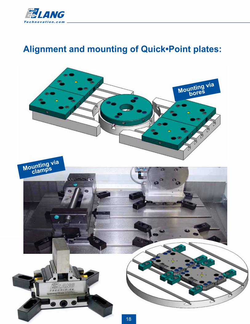
Mounting via bores
Mounting via
clamps
Alignment and mounting of Quick•Point plates:

19
Quick•Point system provides multifunctional and flexible mounting of different fixtures on machine tables, indexers, tombstones, rotary tables or mill-turn machining centers.
Various applications of Quick•Point plates:
4 x 90°

20
The zero-point “entry“ plate by Lang – Mounting of plate on machine table via clamps or bores
Rigid, compact base plate made of case-hardened quality steel. Height 27 mm ± 0,01 mm/1.06“ ± 0.00039“
Mounting of plate on ma-chine tool table via clamps. (Available upon request)
High repeatability due to precision bores
4x M5 thread for 90 degree indexing position for batch production
Tighteningforce 30 Nm
Covers for mounting bores
Mounting of plate via bores
Not only highly precise, but also provides high mechanical load capacity. Example: Weight of workpiece 385 lbs. (175 kg) and 20.70“ (525 mm) height.

21
Quick•Point plate 52 – With 4 mounting bores and clamping edges
Description/Type Weight in lbs. Order No.
Quick•Point plate 52, stud distance 52 mmDimensions 5.91 x 4.57 x 1.06“ (150 x 116 x 27 mm)
6.4 145150
Weitergabe sowie Vervielfaeltigung dieser Unterlage, Verwertung und Mitteilung ihres Inhalts nicht gestattet, soweit nicht ausdruecklich zugestanden. Zuwiderhandlungen verpflichten zu Schadenersatz.Alle Rechte fuer den Fall der Patenterteilung oder Gebrauchsmuster - Eintragung vorhanden.
Copying of this document, and giving it to others and the use or communication of the contents thereof, are forbidden without express authority. Offenders are liable to the payment of damages. All rights are reserved in the event of the grant of a patent or the registration of a utility model or design.
2852
100
50
200+0,0
2
35 35150
116
for M10 or M12
12,02 t = 27 mm
M5
109876543210
Werkstoff:Material:
Oberflächenangabe nach DIN ISO 1302(3141)Surface finih to
Maßstab2:Scale:
Norm
Benennung:Name:
Zeichnungs- Nr. DWG-NO.
Gepr.
Name
Bl.Blz.
Artikel - Nr.
Datum/DateBearb.
allg.ToleranzenDIN 7168 - mBasic Tol.
Maßstab:Scale:
A3
Zust. Änderung/ Datum/Date Name Revision
Zeichnung geschützt nach DIN 34
MaßblattQuick- Point Platte 52er
145150
145150-01
27.01.10 Feuchter
1:1
Quick•Point plate 96 – With 4 mounting bores and clamping edges
Description/Type Weight in lbs Order No.
Quick•Point plate 96, stud distance 96 mmDimensions 7.72 x 6.14 x 1.06“ (192 x 156 x 27 mm)
12.1 145400
The zero-point “entry“ plate by Lang – Mounting of plate on machine table via clamps or bores
Weitergabe sowie Vervielfaeltigung dieser Unterlage, Verwertung und Mitteilung ihres Inhalts nicht gestattet, soweit nicht ausdruecklich zugestanden. Zuwiderhandlungen verpflichten zu Schadenersatz.Alle Rechte fuer den Fall der Patenterteilung oder Gebrauchsmuster - Eintragung vorhanden.
Copying of this document, and giving it to others and the use or communication of the contents thereof, are forbidden without express authority. Offenders are liable to the payment of damages. All rights are reserved in the event of the grant of a patent or the registration of a utility model or design.
96150
28
50
192
156
100
35 35
200+0,0
2
for M10 or M12
12,02t = 27 mm
4x M5
0 1 2 3 54 6 7 8 9 10
DIN A2Zeichnung geschützt nach DIN 34Zust. Änderung/ Datum/Date Name
Revision
A2
Maßstab:Scale:
allg.ToleranzenDIN 7168 - mBasic Tol.
Bearb.Datum/Date
Artikel - Nr.
Bl.Blz.
Name
Gepr.
Zeichnungs- Nr. DWG-NO.
Benennung:Name:
Maßstab2:Scale:
Oberflächenangabe nach DIN ISO 1302(3141)Surface finih to
Werkstoff:Material:
Norm
1:1
27.01.10 Feuchter
145400-01
145400
MaßblattQuick- Point Platte 96er
Quick•Point

22
Quick•Point raster plate 96
Description/Type Weight in lbs. Order No.
Quick•Point raster plate 96, stud distance 96 mmDimensions 7.56 x 7.56 x 1.06“ (192 x 192 x 27 mm)
15.9 145710
Quick•Point raster plate 52
Description/Type Weight in lbs. Order No.
Quick•Point raster plate 52, stud distance 52 mmDimensions 4.09 x 4.09 x 1.06“ (104 x 104 x 27 mm)
4.4 175600
Quick•Point raster plates – Ideal for a variable gridsystem set-up on your machine table
Weitergabe sowie Vervielfaeltigung dieser Unterlage, Verwertung und Mitteilung ihres Inhalts nicht gestattet, soweit nicht ausdruecklich zugestanden. Zuwiderhandlungen verpflichten zu Schadenersatz.Alle Rechte fuer den Fall der Patenterteilung oder Gebrauchsmuster - Eintragung vorhanden.
Copying of this document, and giving it to others and the use or communication of the contents thereof, are forbidden without express authority. Offenders are liable to the payment of damages. All rights are reserved in the event of the grant of a patent or the registration of a utility model or design.
19296
192
72
20
36
8888
36
12,02 t = 27 mm
0 1 2 3 54 6 7 8 9 10
DIN A2Zeichnung geschützt nach DIN 34Zust. Änderung/ Datum/Date Name
Revision
A2
Maßstab:Scale:
allg.ToleranzenDIN 7168 - mBasic Tol.
Bearb.Datum/Date
Artikel - Nr.
Bl.Blz.
Name
Gepr.
Zeichnungs- Nr. DWG-NO.
Benennung:Name:
Maßstab2:Scale:
Oberflächenangabe nach DIN ISO 1302(3141)Surface finih to
Werkstoff:Material:
Norm
1:1
27.01.10 Feuchter
145710-01
145710
MaßblattQuick- Point Platte 96er
Weitergabe sowie Vervielfaeltigung dieser Unterlage, Verwertung und Mitteilung ihres Inhalts nicht gestattet, soweit nicht ausdruecklich zugestanden. Zuwiderhandlungen verpflichten zu Schadenersatz.Alle Rechte fuer den Fall der Patenterteilung oder Gebrauchsmuster - Eintragung vorhanden.
Copying of this document, and giving it to others and the use or communication of the contents thereof, are forbidden without express authority. Offenders are liable to the payment of damages. All rights are reserved in the event of the grant of a patent or the registration of a utility model or design.
52
104
104
82
12,02
t = 27 mm
for M10
109876543210
Werkstoff:Material:
Oberflächenangabe nach DIN ISO 1302(3141)Surface finih to
Maßstab2:Scale:
Norm
Benennung:Name:
Zeichnungs- Nr. DWG-NO.
Gepr.
Name
Bl.Blz.
Artikel - Nr.
Datum/DateBearb.
allg.ToleranzenDIN 7168 - mBasic Tol.
Maßstab:Scale:
A3
Zust. Änderung/ Datum/Date Name Revision
Zeichnung geschützt nach DIN 34
1:1
MaßblattQuick- Point Platte 52er
175600
175600-01
27.01.10 Feuchter
Mounting bores can be machined in the shaded area only. Prices upon request

23
Mounting via bores on machine table:
Universal 96 mm/ 3.86“ grid system with Quick•Point plates 145710 on machine table.Various positions on grid system can be achievedusing raster plates.
T-slots of the machine table can be used to attach and align the Quick•Point plates also.
Quick•Point

24
Quick•Point round plate 96 – With center bore Ø 62 + 0,03 mm / 2.44“, stud distance 96 mm
Description/Type Weight in lbs. Order No.
Quick•Point round plate 96, Ø 196 mm, with center bore, without mounting bores. 11.9 145822
Quick•Point round plate 96, Ø 246 mm, with center bore, without mounting bores. 19.6 145842
Quick•Point round plate 96 – Diameter 7.71“ (196 mm) , stud distance 96 mm
Description/Type Weight in lbs. Order No.
Quick•Point round plate 96, Ø 196 mm, without mounting bores 13.2 145820
Mounting bores can be machined in the shaded area only. Prices upon request
Mounting bores can be machined in the shaded area only. Prices upon request
Quick•Point round plates – Ideal adaptation forindexers, 5-axis machining, rotary tables or combinedmill-turn machining
Weitergabe sowie Vervielfaeltigung dieser Unterlage, Verwertung und Mitteilung ihres Inhalts nicht gestattet, soweit nicht ausdruecklich zugestanden. Zuwiderhandlungen verpflichten zu Schadenersatz.Alle Rechte fuer den Fall der Patenterteilung oder Gebrauchsmuster - Eintragung vorhanden.
Copying of this document, and giving it to others and the use or communication of the contents thereof, are forbidden without express authority. Offenders are liable to the payment of damages. All rights are reserved in the event of the grant of a patent or the registration of a utility model or design.
196
2896
16
72
120
20
12 ,02
4x M5
t = 27 mm
0 1 2 3 54 6 7 8 9 10
DIN A2Zeichnung geschützt nach DIN 34Zust. Änderung/ Datum/Date Name
Revision
A2
Maßstab:Scale:
allg.ToleranzenDIN 7168 - mBasic Tol.
Bearb.Datum/Date
Artikel - Nr.
Bl.Blz.
Name
Gepr.
Zeichnungs- Nr. DWG-NO.
Benennung:Name:
Maßstab2:Scale:
Oberflächenangabe nach DIN ISO 1302(3141)Surface finih to
Werkstoff:Material:
Norm
27.01.10 Feuchter
1:1
145820-01
145820
MaßblattQuick- Point Platte 96er
Weitergabe sowie Vervielfaeltigung dieser Unterlage, Verwertung und Mitteilung ihres Inhalts nicht gestattet, soweit nicht ausdruecklich zugestanden. Zuwiderhandlungen verpflichten zu Schadenersatz.Alle Rechte fuer den Fall der Patenterteilung oder Gebrauchsmuster - Eintragung vorhanden.
Copying of this document, and giving it to others and the use or communication of the contents thereof, are forbidden without express authority. Offenders are liable to the payment of damages. All rights are reserved in the event of the grant of a patent or the registration of a utility model or design.
96
246
72
68
120
22
196
(1
4582
2)
t = 27 mm
62 0+0,03
0 1 2 3 54 6 7 8 9 10
DIN A2Zeichnung geschützt nach DIN 34Zust. Änderung/ Datum/Date Name
Revision
A2
Maßstab:Scale:
allg.ToleranzenDIN 7168 - mBasic Tol.
Bearb.Datum/Date
Artikel - Nr.
Bl.Blz.
Name
Gepr.
Zeichnungs- Nr. DWG-NO.
Benennung:Name:
Maßstab2:Scale:
Oberflächenangabe nach DIN ISO 1302(3141)Surface finih to
Werkstoff:Material:
Norm
27.01.10 Feuchter
1:1
145842-01
145842
MaßblattQuick- Point Platte 96er

25
Quick•Point round plate 52 - Diameter 6.18“ (157 mm), stud distance 52 mm
Description/Type Weight in lbs. Order No.
Quick•Point round plate 52, Ø157mm, with mounting bores 7.7 145900 Weitergabe sowie Vervielfaeltigung dieser Unterlage, Verwertung und Mitteilung ihres Inhalts nicht gestattet, soweit nicht ausdruecklich zugestanden. Zuwiderhandlungen verpflichten zu Schadenersatz.Alle Rechte fuer den Fall der Patenterteilung oder Gebrauchsmuster - Eintragung vorhanden.
Copying of this document, and giving it to others and the use or communication of the contents thereof, are forbidden without express authority. Offenders are liable to the payment of damages. All rights are reserved in the event of the grant of a patent or the registration of a utility model or design.
52
100
28
96
52
20 0+0,02
157
96
t = 27 mm
4x M5
for M10 or M12
for M8
12,02
0 1 2 3 54 6 7 8 9 10
DIN A2Zeichnung geschützt nach DIN 34Zust. Änderung/ Datum/Date Name
Revision
A2
Maßstab:Scale:
allg.ToleranzenDIN 7168 - mBasic Tol.
Bearb.Datum/Date
Artikel - Nr.
Bl.Blz.
Name
Gepr.
Zeichnungs- Nr. DWG-NO.
Benennung:Name:
Maßstab2:Scale:
Oberflächenangabe nach DIN ISO 1302(3141)Surface finih to
Werkstoff:Material:
Norm
145900-01
145900
MaßblattQuick- Point Platte 52er
1:1
27.01.10 Feuchter
Rotary table equipped with round Quick•Point plate on 5-axis Haas machine.
Quick•Point
52 mm
96 mm
Use your Quick•Point plate 145900 as an adapter!
Transform Quick•Point plate 145900 to Quick•Point adapter plate by simply adding clamping studs!

26
Quick•Point support plates, soft – For individualadaptation of fixtures and other devices
Steel support plates, soft
Description/Type Weight in lbs. Order No.
Support plate 156 - Dimensions 6.14 x 6.14 x .95“ (156 x 156 x 24 mm) 11.7 145575
Support plate 245 - Dimensions 9.64 x 9.64 x .95“ (245 x 245 x 24 mm) 24.8 145675
Use support plates for a quick change-over of clamping fixtures.
Quick•Point adapter plate
Description/Type Weight in lbs. Order No.
Quick•Point adapter plate - Dimensions 5.91“ x 4.96“ (150 x 126 mm) 7.5 145160
52 mm
96 mm
Quick•Point adapter plate – For reduction of stud distance from 3.79“ to 2.05“ (96 mm to 52 mm)
Example
of use
27
Sub-base for Quick•Point plates – Increase accessibility to workpiece on 5-axis machine tools
Weitergabe sowie Vervielfaeltigung dieser Unterlage, Verwertung und Mitteilung ihres Inhalts nicht gestattet, soweit nicht ausdruecklich zugestanden. Zuwiderhandlungen verpflichten zu Schadenersatz.Alle Rechte fuer den Fall der Patenterteilung oder Gebrauchsmuster - Eintragung vorhanden.
Copying of this document, and giving it to others and the use or communication of the contents thereof, are forbidden without express authority. Offenders are liable to the payment of damages. All rights are reserved in the event of the grant of a patent or the registration of a utility model or design.
16 0+0,02
M10
23 28
20 ±0,03
19
10,5
16 0+0,02
0,5x
45
2,1+
0,1
12,6M8
1618
20 ±0,03
14,5
8,5
12 0+0,02
0,5x
45
2,1+
0,1
0,5x
45
10,6
12 0+0,02
5,5 0,5x
45
6
0 1 2 3 54 6 7 8 9 10
DIN A2Zeichnung geschützt nach DIN 34Zust. Änderung/ Datum/Date Name
Revision
A2
Maßstab:Scale:
allg.ToleranzenDIN 7168 - mBasic Tol.
Bearb.Datum/Date
Artikel - Nr.
Bl.Blz.
Name
Gepr.
Zeichnungs- Nr. DWG-NO.
Benennung:Name:
Maßstab2:Scale:
Oberflächenangabe nach DIN ISO 1302(3141)Surface finih to
Werkstoff:Material:
Norm
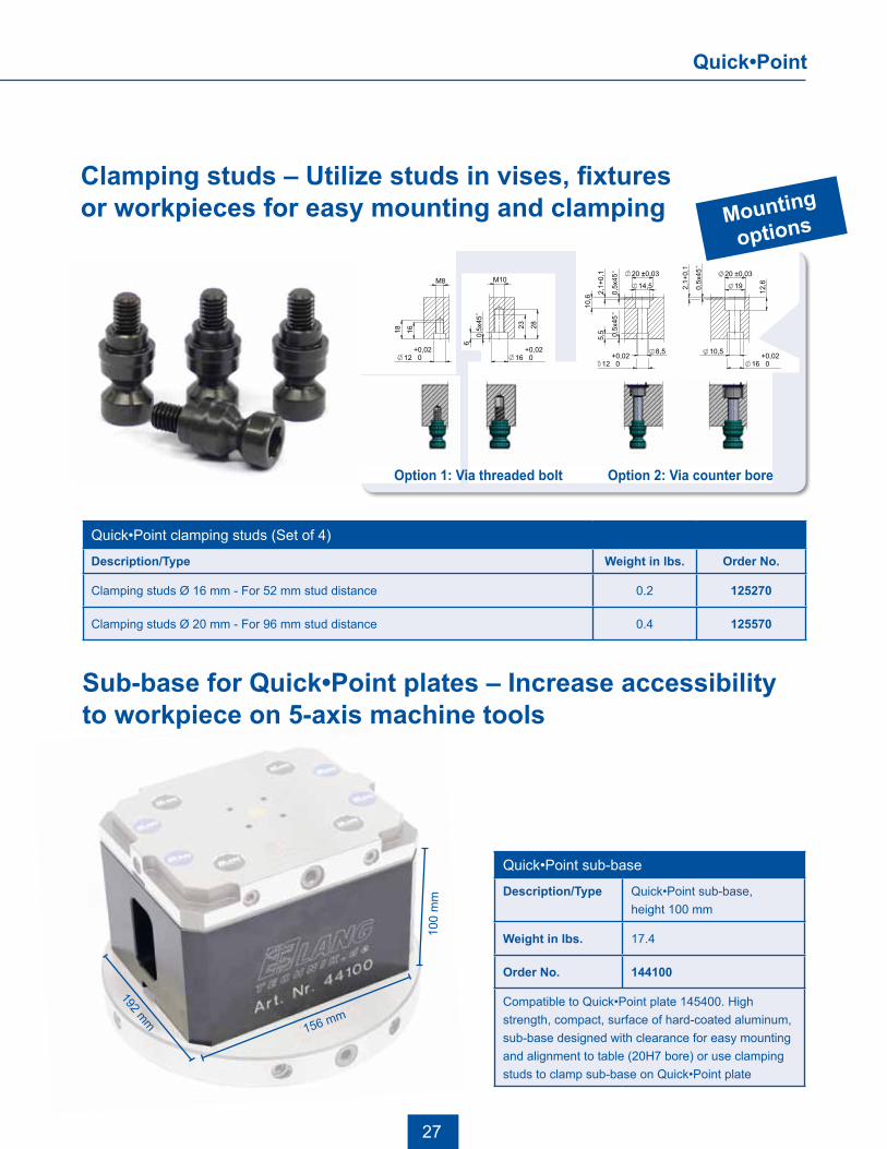
Clamping studs – Utilize studs in vises, fixturesor workpieces for easy mounting and clamping
Quick•Point clamping studs (Set of 4)
Description/Type Weight in lbs. Order No.
Clamping studs Ø 16 mm - For 52 mm stud distance 0.2 125270
Clamping studs Ø 20 mm - For 96 mm stud distance 0.4 125570
Quick•Point sub-base
Description/Type Quick•Point sub-base,height 100 mm
Weight in lbs. 17.4
Order No. 144100
Compatible to Quick•Point plate 145400. High strength, compact, surface of hard-coated aluminum, sub-base designed with clearance for easy mounting and alignment to table (20H7 bore) or use clamping studs to clamp sub-base on Quick•Point plate
Weitergabe sowie Vervielfaeltigung dieser Unterlage, Verwertung und Mitteilung ihres Inhalts nicht gestattet, soweit nicht ausdruecklich zugestanden. Zuwiderhandlungen verpflichten zu Schadenersatz.Alle Rechte fuer den Fall der Patenterteilung oder Gebrauchsmuster - Eintragung vorhanden.
Copying of this document, and giving it to others and the use or communication of the contents thereof, are forbidden without express authority. Offenders are liable to the payment of damages. All rights are reserved in the event of the grant of a patent or the registration of a utility model or design.
16 0+0,02
M10
23 28
20 ±0,03
19
10,5
16 0+0,02
0,5x
45
2,1+
0,1
12,6M8
1618
20 ±0,03
14,5
8,5
12 0+0,02
0,5x
45
2,1+
0,1
0,5x
45
10,6
12 0+0,02
5,5 0,5x
45
6
0 1 2 3 54 6 7 8 9 10
DIN A2Zeichnung geschützt nach DIN 34Zust. Änderung/ Datum/Date Name
Revision
A2
Maßstab:Scale:
allg.ToleranzenDIN 7168 - mBasic Tol.
Bearb.Datum/Date
Artikel - Nr.
Bl.Blz.
Name
Gepr.
Zeichnungs- Nr. DWG-NO.
Benennung:Name:
Maßstab2:Scale:
Oberflächenangabe nach DIN ISO 1302(3141)Surface finih to
Werkstoff:Material:
Norm
Weitergabe sowie Vervielfaeltigung dieser Unterlage, Verwertung und Mitteilung ihres Inhalts nicht gestattet, soweit nicht ausdruecklich zugestanden. Zuwiderhandlungen verpflichten zu Schadenersatz.Alle Rechte fuer den Fall der Patenterteilung oder Gebrauchsmuster - Eintragung vorhanden.
Copying of this document, and giving it to others and the use or communication of the contents thereof, are forbidden without express authority. Offenders are liable to the payment of damages. All rights are reserved in the event of the grant of a patent or the registration of a utility model or design.
16 0+0,02
M10
23 28
20 ±0,03
19
10,5
16 0+0,02
0,5x
45
2,1+
0,1
12,6M8
1618
20 ±0,03
14,5
8,5
12 0+0,02
0,5x
45
2,1+
0,1
0,5x
45
10,6
12 0+0,02
5,5 0,5x
45
60 1 2 3 54 6 7 8 9 10
DIN A2Zeichnung geschützt nach DIN 34Zust. Änderung/ Datum/Date Name
Revision
A2
Maßstab:Scale:
allg.ToleranzenDIN 7168 - mBasic Tol.
Bearb.Datum/Date
Artikel - Nr.
Bl.Blz.
Name
Gepr.
Zeichnungs- Nr. DWG-NO.
Benennung:Name:
Maßstab2:Scale:
Oberflächenangabe nach DIN ISO 1302(3141)Surface finih to
Werkstoff:Material:
Norm
Weitergabe sowie Vervielfaeltigung dieser Unterlage, Verwertung und Mitteilung ihres Inhalts nicht gestattet, soweit nicht ausdruecklich zugestanden. Zuwiderhandlungen verpflichten zu Schadenersatz.Alle Rechte fuer den Fall der Patenterteilung oder Gebrauchsmuster - Eintragung vorhanden.
Copying of this document, and giving it to others and the use or communication of the contents thereof, are forbidden without express authority. Offenders are liable to the payment of damages. All rights are reserved in the event of the grant of a patent or the registration of a utility model or design.
16 0+0,02
M10
23 28
20 ±0,03
19
10,5
16 0+0,02
0,5x
45
2,1+
0,1
12,6M8
161820 ±0,03
14,5
8,5
12 0+0,02
0,5x
45
2,1+
0,1
0,5x
45
10,6
12 0+0,02
5,5 0,5x
45
6
0 1 2 3 54 6 7 8 9 10
DIN A2Zeichnung geschützt nach DIN 34Zust. Änderung/ Datum/Date Name
Revision
A2
Maßstab:Scale:
allg.ToleranzenDIN 7168 - mBasic Tol.
Bearb.Datum/Date
Artikel - Nr.
Bl.Blz.
Name
Gepr.
Zeichnungs- Nr. DWG-NO.
Benennung:Name:
Maßstab2:Scale:
Oberflächenangabe nach DIN ISO 1302(3141)Surface finih to
Werkstoff:Material:
Norm
Weitergabe sowie Vervielfaeltigung dieser Unterlage, Verwertung und Mitteilung ihres Inhalts nicht gestattet, soweit nicht ausdruecklich zugestanden. Zuwiderhandlungen verpflichten zu Schadenersatz.Alle Rechte fuer den Fall der Patenterteilung oder Gebrauchsmuster - Eintragung vorhanden.
Copying of this document, and giving it to others and the use or communication of the contents thereof, are forbidden without express authority. Offenders are liable to the payment of damages. All rights are reserved in the event of the grant of a patent or the registration of a utility model or design.
16 0+0,02
M10
23 28
20 ±0,03
19
10,5
16 0+0,02
0,5x
45
2,1+
0,1
12,6M8
1618
20 ±0,03
14,5
8,5
12 0+0,02
0,5x
45
2,1+
0,1
0,5x
45
10,6
12 0+0,02
5,5 0,5x
45
6
0 1 2 3 54 6 7 8 9 10
DIN A2Zeichnung geschützt nach DIN 34Zust. Änderung/ Datum/Date Name
Revision
A2
Maßstab:Scale:
allg.ToleranzenDIN 7168 - mBasic Tol.
Bearb.Datum/Date
Artikel - Nr.
Bl.Blz.
Name
Gepr.
Zeichnungs- Nr. DWG-NO.
Benennung:Name:
Maßstab2:Scale:
Oberflächenangabe nach DIN ISO 1302(3141)Surface finih to
Werkstoff:Material:
Norm
Option 1: Via threaded bolt Option 2: Via counter bore
Mounting
options
Quick•Point
192 mm
156 mm
100
mm
28
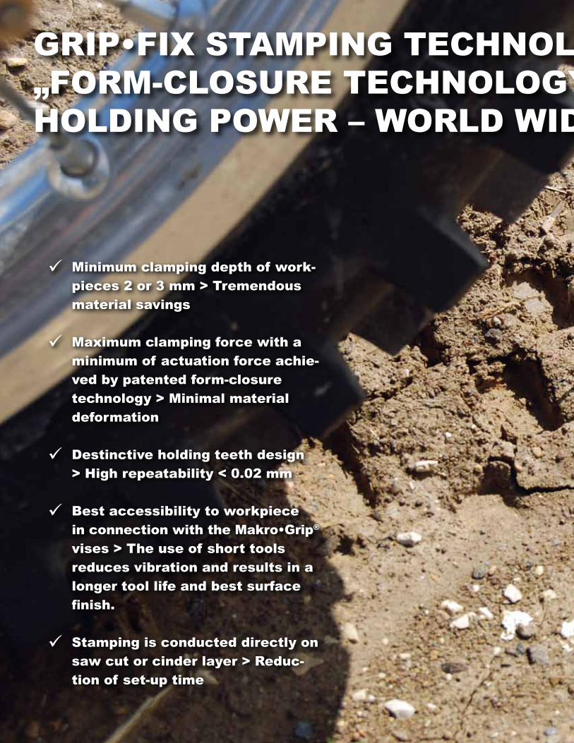
Minimumclampingdepthofwork- pieces2or3mm>Tremendous materialsavings
Maximumclampingforcewitha minimumofactuationforceachie- vedbypatentedform-closure technology>Minimalmaterial deformation
Destinctiveholdingteethdesign >highrepeatability<0.02mm
Bestaccessibilitytoworkpiece inconnectionwiththeMakro•Grip® vises>Theuseofshorttools reducesvibrationandresultsina longertoollifeandbestsurface finish.
stampingisconducteddirectlyon sawcutorcinderlayer>reduc- tionofset-uptime
GrIP•FIxsTaMPInGTeChnOlOGY!OurPaTenTeD„FOrM-ClOsureTeChnOlOGY“GuaranTeesMaxIMuMhOlDInGPOwer–wOrlDwIDe!

29
Holding tooth
Stamped/indented recess
Control marks
Grip•Fix jaw
WorkpieceHolding teeth Ideal stamping marks on work-
piece - Control marks should be slightly visible
GrIP•FIxsTaMPInGTeChnOlOGY!OurPaTenTeD„FOrM-ClOsureTeChnOlOGY“GuaranTeesMaxIMuMhOlDInGPOwer–wOrlDwIDe!
30
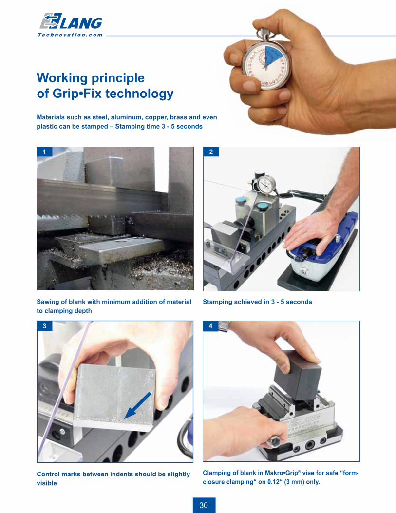
Materials such as steel, aluminum, copper, brass and even plastic can be stamped – Stamping time 3 - 5 seconds
Working principleof Grip•Fix technology
Sawing of blank with minimum addition of material to clamping depth
21
Stamping achieved in 3 - 5 seconds
3
Control marks between indents should be slightly visible
4
Clamping of blank in Makro•Grip® vise for safe “form-closure clamping“ on 0.12“ (3 mm) only.

31
Operation by hand or footQuick jaw adjustment for different sizes of workpiece
Max. clamping range 9.65“ respectively 13.98“ - Jaw width 4.96“
Scaled endstop for quick positioning of workpiece
Solid and rigid base –designed for up to 20 tons of stamping force
Stamping unit for the work bench
Included in delivery:• Stamping vise with stamping jaws• Parallels, standard 0.12“ stamping height• Pneumatic-hydraulic power multiplier 435 - 5,801 psi
Standard stamping unit,clamping range max. 9.65“ (245 mm)
Base lengthin inch
Weightin lbs.
Order No.with Standard jaws
Order No. with High end jaws
19.69“ 121.3 141200 141201
Stamping unit extended version,clamping range max. 13.98“ (355 mm)
24.64“ 143.3 141350 141351
• Scaled workpiece endstop• Protection shield• Gauging blocks to measure the depth of the holding teeth
Grip•Fix
Stamping unit: Ideal for a cost-effective start in stamping technology.
Stamping jaws with parallels 0.12“ (3 mm)
Type/Description Weight in lbs. Order No.
Standard 3.1 141111
High end 3.1 141112
Standard jaws for all materials up to 35 HRC (part ident. #20 on back).High-end stamping jaws for stamping high strength materials up to 45 HRC (part ident. #15 on back)

LANG Technovation Co. Tel.: 262 446 9850Fax: 262 446 9851Email: [email protected]: www.lang-technovation.com