20080715 166 · jean-paul a. nasser, esq. reg. no. 53372 naval undersea warfare center newport, ri...
TRANSCRIPT
DEPARTMENT OF THE NAVYNAVAL UNDERSEA WARFARE CENTER
DIVISION NEWPORT.... OFFICE OF COUNSEL
PHONE: 401 832-3653NEWPORT FAX: 401 832-4432
DSN: 432-3653
Attorney Docket No. 80227Date: 2 July 2008
The below identified patent application is available forlicensing. Requests for information should be addressed to:
TECHNOLOGY PARTNERSHIP ENTERPRISE OFFICENAVAL UNDERSEA WARFARE CENTER1176 HOWELL ST.CODE 07TP, BLDG. 990NEWPORT, RI 02841
Serial Number 11/650,761
Filing Date 26 December 2006
Inventor Erich M. Gerhard
Address any questions concerning this matter to the Office ofTechnology Transfer at (401) 832-1511.
DISTRIBUTION STATEMENTApproved for Public ReleaseDistribution is unlimited
20080715 166
Attorney Docket No. 80227Customer No. 23523
BUOYANT CABLE ANTENNA SYSTEM
TO ALL WHOM IT MAY CONCERN:
BE IT KNOWN THAT HEIDI R. PICKEREIGN, the administrator of
the estate of ERICH M. GERHARD, employee of the United States
Government, late citizen of the United States of America, and
late resident of South Kingstown, County of Washington, State of
Rhode Island, has invented certain new and useful improvements
entitled as set forth above of which the following is a
specification.
JEAN-PAUL A. NASSER, ESQ.Reg. No. 53372Naval Undersea Warfare CenterNewport, RI Division Newport 02841-1708TEL: 401-832-4736FAX: 401-832-1231
1
Attorney Docket No. 80227
BUOYANT CABLE ANTENNA SYSTEM
STATEMENT OF THE GOVERNMENT INTEREST
[0001] The invention described herein may be manufactured and
used by or for the Government of the United States of America
for Governmental purposes without the payment of any royalties
thereon or therefore.
CROSS REFERENCE TO RELATED PATENT APPLICATION
[0002] The instant application is related to three co-pending
U.S. Patent Applications entitled BUOYANT CABLE ANTENNA SYSTEM
AND METHOD WITH ARTICULATING BLOCKS (Navy Case No. 80224),
BUOYANT CABLE ANTENNA CONFIGURATION AND SYSTEM (Navy Case No.
80225), and SERPENTINE BUOYANT CABLE ANTENNA SYSTEM (Navy Case
No. 80226), having the same filing date.
BACKGROUND OF THE INVENTION
(1) Field of the Invention
[0003] The present invention relates generally to a flexible
antenna system and, in a more particular preferred embodiment,
to a buoyant cable antenna system with extended frequency range
capability.
2
(2) Description of the Prior Art
[0004] Buoyant cable antennas are well known for use by
submarines when the submarine is submerged. Such cables have
been used to receive radio signals in the very low frequency and
low frequency (VLF/LF) transmission bands. For instance,
present buoyant cable antenna systems consist of a horizontal
wire antenna for reception of signals in the range of from about
10 kHz to 130 kHz.
[0005] The buoyant cable antenna floats on the ocean surface
and is deployed with a buoyant cable. The horizontal antenna
element lies on the surface of the ocean and reception is
limited by transmission line attenuation, amplifier gain and
antenna characteristics. Seawater attenuation, antenna gain and
frequency patterns limit the usefulness of the horizontal
antenna element.
[0006] The buoyant cable antenna must be flexible because a
submerged submarine preferably launches the cable antenna
through a transfer mechanism which bends the cable through a
six-inch radius. Because flexibility is required, buoyant cable
antennas have employed a horizontal wire antenna element which
receives signals from the fore and aft (front and back)
direction relative to its deployment. The limited antenna gain
pattern limits the reception capability of the buoyant cable
antenna.
3
[0007] Various inventors have addressed similar problems
related to buoyant cable antennas as discussed in the following
patents. U.S. Patent No. 5,933,117, issued August 3, 1999, to
the present inventor Erich M. Gerhard, is incorporated herein by
reference, and discloses a buoyant loop antenna, deployable
along a cable, which includes a core region comprising a
plurality of annular ferrite beads. These annular shaped beads
include a center hole and a generally concave first end and a
generally convex second end. The ferrite beads are aligned with
the concave end of one bead against the convex end of another
bead. This allows the cable to flex while the beads maintain
contact with each other, providing flexibility and resistance to
crushing. The core region has a loop wire wrapped helically
around it, forming the loop antenna. The loop wire element
starts and ends at the same end of the core region, forming a
loop. This loop allows transmission and reception in an athwart
(side to side) direction. This wire loop antenna can be
combined with a straight wire antenna (which provides reception
in a fore and aft direction) to provide an omni-directional
cable antenna assembly for VLF/LF frequency ranges.
[0008] U.S. Patent No. 1,667,510, issued April 24, 1928, to
J. R. Coe, discloses a cable constituting an electrical
conductor for high tension transmission lines having, in
combination, a core comprising a plurality of short rigid
4
members arranged end to end, and contacting wires of high
electrical conductivity arranged spirally and side by side about
said members.
[0009] U.S. Patent No. 1,810,079, issued June 16, 1931, to
H.C. Jennison, discloses a conducting cable comprising a series
of cups constituting a supporting means comprising a plurality
of diaphragms and round contacting conductors spirally wound
about the supporting means. The several cups have on their
sides longitudinally extending surfaces aligning the cups within
the spirally wound conductors. Adjacent end portions of
adjacent cups are suitably nested so as to form ball and socket
joints between them.
[0010] U.S. Patent No. 2,419,053, issued July 3, 1942, to C.
E. Bennett, discloses an electric cable in which the weight to
volume ratio is such to render the cable buoyant. The cable
comprises a continuous water pervious tubular member, conductor
strands laid up about the tubular member or core, and a sheath
of insulating material about the conductor strands. Floats are
threaded upon the sheath and rigidly secured thereto. The
adjacent ends of the floats are telescoping with each other
while permitting relative angular movement to provide a flexible
structure.
[0011] U.S. Patent No. 4,978,966, issued December 18, 1990,
to Takizawa et al., discloses an antenna with a plurality of
5
rod-shaped cores aligned in an end-to-end relationship and an
antenna coil wound on the core array throughout its entire
length. This arrangement permits the antenna to bend and fit a
curved surface of a car where the antenna is mounted.
[0012] U.S. Patent No. 2,428,480, issued October 7, 1947, to
H. A. Tunstall, discloses a tubular buoyancy element comprising
a longitudinally flexible helix resistant to radial compression
and a flexible waterproof covering enclosing the helix. Means
comprising expanded rubber plugs are provided within the
covering and have peripheral surfaces molded to and closely
fitting the internal surface thereof for dividing the interior
of the element into a plurality of closed compartments.
[0013] U.S. Patent No. 3,117,596, issued January 14, 1964,
discloses a buoyant flexible hose comprising helically wound
reinforcement means comprising a pair of tubular members in
laterally adjacent relation and having longitudinally spaced
convolutions and a plastic carcass enclosing at least a portion
of the reinforcement means. The carcass comprises an inner
tubular wall portion and an outer helically corrugated wall
portion having the valley portions thereof secured to opposed
portions of said inner wall portion. A portion of the
reinforcement means is disposed between the peak portions of the
corrugated outer wall portion and opposed portions of the inner
wall portion. Sealed helical air spaces are formed between the
6

portion of the reinforcement means and opposed surface portions
of the carcass wall portions enclosing the same. The sealed air
spaces are disposed on either side of the portion of the
reinforcement means.
[0014] U.S. Patent No. 3,823,249, issued July 9, 1974, to
Floessel et al., discloses a compressed gas insulated electrical
high voltage conductor assembly comprised of a number of
pressurized gas filled rigid straight sections arranged in end
to end relation. Each section is constituted by a length of a
rigid metallic tubular member which encloses and supports
centrally therein a rigid portion of the electrical conductor.
These rigid conductor enclosing section are joined together by
means of short flexible sections of the tubular enclosing member
and a corresponding flexible portion of the conductor thereby to
enable the connected together rigid sections to be bent through
an angle of substantially 180 degrees to facilitate transport
from the fabrication point to a remote location for on site
installation.
[0015] U.S. Patent No. 5,561,640, issued October 1, 1996, to
W. C. Maciejewski, discloses a sonar array cable typically
provided in lengths comprising hydrophone arrays and associated
electronics and transmitter can components, with each cable
length or section having one of each of these components housed
therein. These sections are relatively stiff and unbendable,
7
requiring that they be connected with relatively bendable
intermediate segments. These intermediate segments are
susceptible to excessive bending that can lead to failure of the
wiring provided therebetween. The wiring in these intermediate
bendable segments is provided in the form of a coil, each coil
is rigidly connected to the transmitter and electronics in one
cable section, and the other end of the coil being connected
electrically to the wiring associated with the hydrophone array
in an adjacent cable section. Each coil is encased in
relatively soft urethane material, preferably in one portion of
the bendable segment, another portion of the bendable segment
having the coil connected at its other end to a relatively still
urethane material associated with the transmitter can and
associated electronics.
[0016] U.S. Patent No. 4,346,953, issued August 31, 1982, to
Carnaghan et al., discloses a flexible coupling assembly for a
radio antenna of a submarine buoyant cable antenna system is
connected in a cable line that retains the characteristics of
the cable as regards the outside diameter, flexibility tensile
strength and electrical continuity. The assembly comprises
flexible co-axial connectors at each end keyed to an insulator
that press fit in a transition piece. The transition piece is
press fit into the tubing by barbed type annular rings machined
into the transition piece. Between the insulators and enclosed
8

by the tubing are plastic pieces connected by a coil spring.
[0017] U.S. Patent No. 5,745,436, issued April 28, 1998, to
S. H. Bittleston, discloses a semi-dry marine seismic streamer
cable that consists of a number of connected streamer cable
sections which each comprise a mechanical jacket surrounding a
hollow core enclosing the seismic sensor and signal transfer
means. Elongated axial stress elements for transmitting axial
loads and a radial reinforcement member for relieving radial
loads are provided in the jacket. The core is filled with a
fluid or fluid saturated foam and the sensor means are mounted
in the core by vibration isolating elements.
[0018] The above cited prior art discloses buoyant antenna
cables which, at best, are limited in frequency range and which
are limited as to the types of antennas which can be used
therewith. Those skilled in the art will appreciate the present
invention that addresses the above and other problems.
SUMMARY OF THE INVENTION
[0019] Accordingly, it is an object of the present invention
to provide an improved buoyant cable system.
[00201 It is another object of the present invention to use a
coil form to provide a suitable shape for a platform that is
flexible for deployment purposes.
[00211 It is yet another object of the present invention to
9
provide an improved towed platform for supporting one or more
antennas having a wide frequency response.
[0022] It is yet another object of the present invention to
provide an improved platform with one or more curves that
provide support in the water.
[0023] These and other objects, features, and advantages of
the present invention will become apparent from the drawings,
the descriptions given herein, and the appended claims.
[0024] In accordance with the present invention, a buoyant,
flexible antenna system is operable for use in water with a
transmission line. The system comprises elements such as, for
instance, at least one linear platform for towing in the water
with the transmission line. The linear platform may have a
selected shape with one or more curved sections that extend
outwardly away from a theoretical centerline of the at least one
linear platform. The linear platform may be comprised of a
flexible construction and may preferably have a memory of a
selected shape. The flexible construction may be operable for
flexing during a deployment into the water and for returning to
the selected shape after the deployment into the water. In a
preferred embodiment, one or more antennas are mounted to the at
least one linear platform.
[0025] In one embodiment, a rotary connector is used between
the at least one linear platform and the transmission line. For
10

instance, a weight may be mounted to the one or more curved
portions such that when separated from the transmission line
with a rotary connector, the weighted curved portion acts as a
keel for supporting the antenna in a desired position. The
weight may be mounted at an apex of the curved portion.
[0026] In another embodiment, the linear platform may
comprise a first curved section and a second curved section such
that the first curved section and the second curved section
extend outwardly from the theoretical centerline in opposite
directions.
(0027] In one presently preferred embodiment, the one or more
curved portions further comprise a spring form.
(0028] A method for a buoyant cable system in accord with the
present invention may comprise steps such as, for instance,
providing a flexible linear construction for attachment to a
transmission line wherein the flexible construction and the
transmission line may be deployable into water. The flexible
linear construction may have memory of a selected shape. Other
steps may include mounting an antenna with respect to the
flexible linear construction. Moreover the method may comprise
steps such as providing that the selected shape has one or more
curves therein and/or providing a curved shape to form a keel
for supporting the antenna. In one embodiment, steps may
include forming the flexible linear construction with a spring
11
coil. In another embodiment steps may include forming the
flexible linear construction with one or more shaped memory
alloy wires. In this embodiment additional steps may include
heating the one or more wires after deployment to return to the
selected shape.
BRIEF DESCRIPTION OF THE DRAWINGS
[0029] A more complete understanding of the invention and
many of the attendant advantages thereto will be readily
appreciated as the same becomes better understood by reference
to the following detailed description when considered in
conjunction with the accompanying drawings wherein corresponding
reference characters indicate corresponding parts throughout
several views of the drawings and wherein:
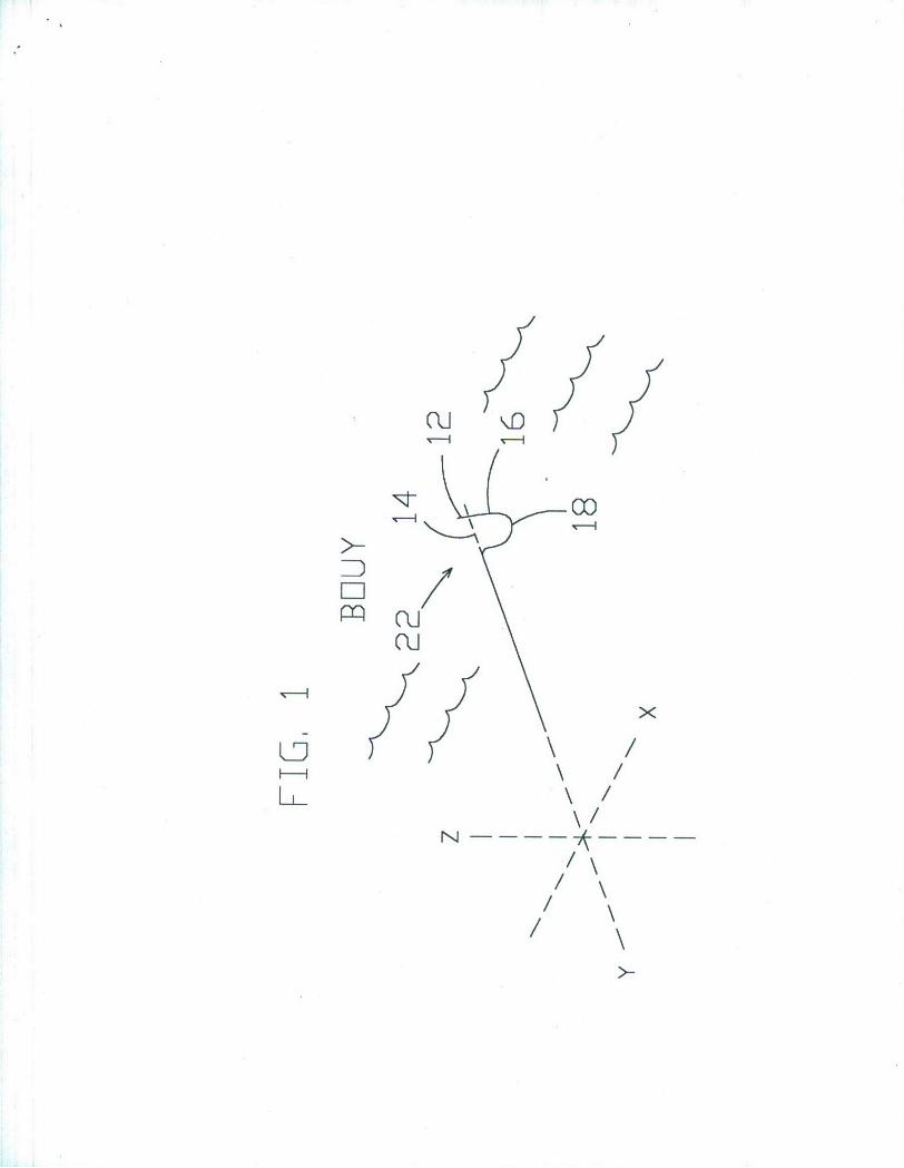
[0030] FIG. 1 is a schematic diagram of one embodiment of a
curved cable antenna in accord with the present invention;
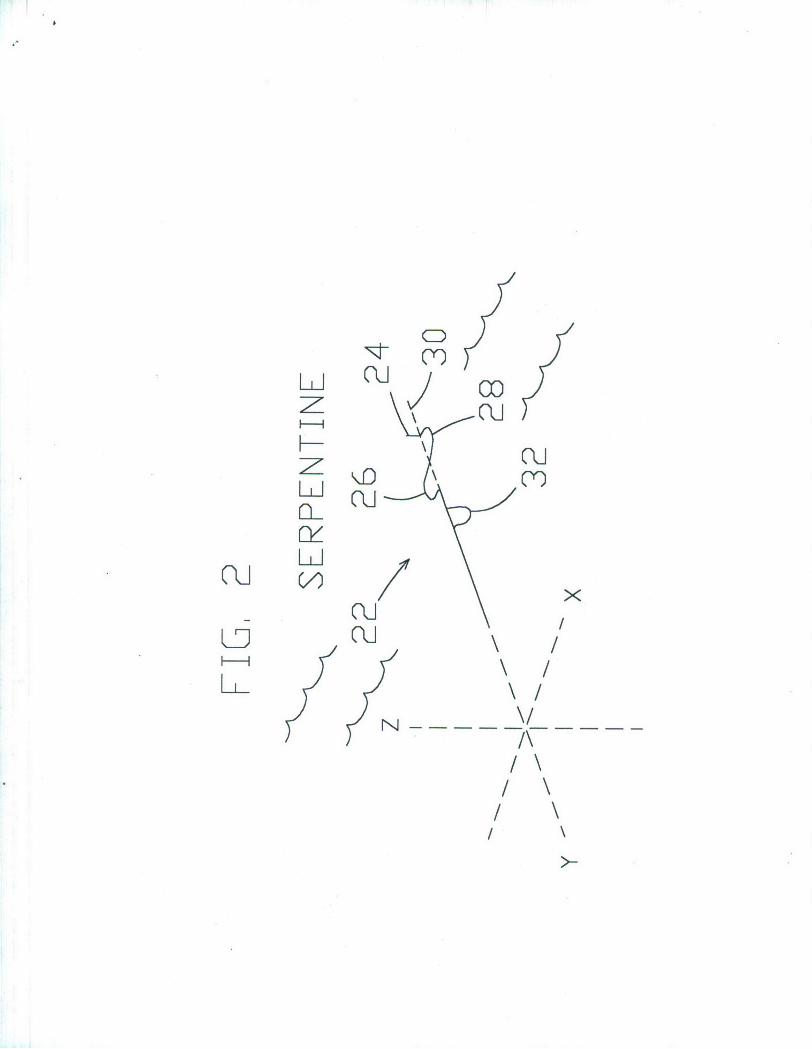
[0031] FIG. 2 is a schematic diagram of another embodiment of
a curved cable antenna in accord with the present invention;
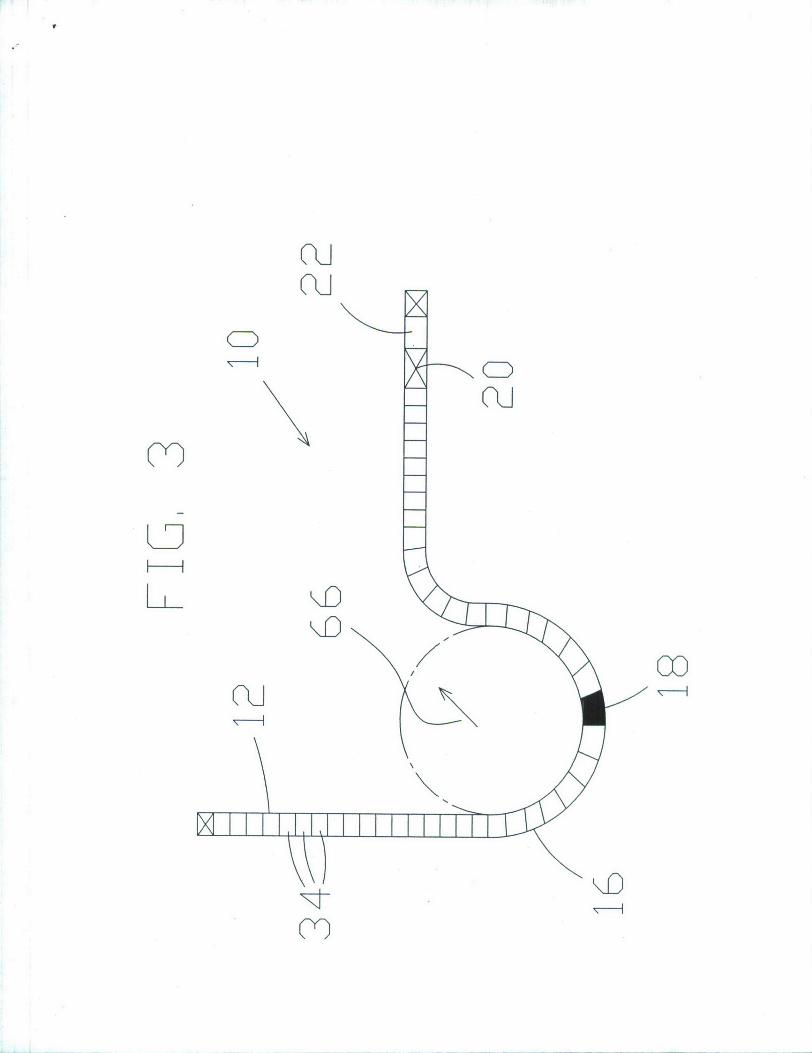
[0032] FIG. 3 is a diagrammatic view of a curved antenna
comprised of a spring coil form in accord with the present
invention; and
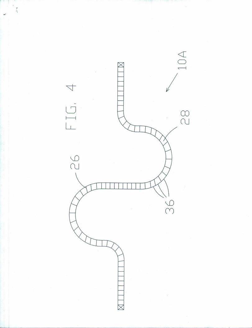
[0033] FIG. 4 is a diagrammatic view of another embodiment of
a curved antenna comprised of a spring coil form in accord with
the present invention.
12
DESCRIPTION OF THE PREFERRED EMBODIMENTS
[0034] The present invention utilizes a curved buoyant cable
antenna that can be deployed by a submerged submarine. The
present invention can be used to provide extended frequency
range capability to a buoyant cable antenna system. Besides
increased frequency band reception, the antenna provides
improved frequency gain and pattern enhancements. The flexible
shape permits passage through deployment mechanisms. A
construction is provided that is flexible but yet has memory to
remember the desired shape after deployment.
[0035] Referring now to the drawings, and more particularly
to FIG. 1 and FIG. 2, there is shown two possible embodiments of
desirable antenna structures that form towed buoyant platforms
10 and 10A, respectively, in accord with the present invention.
Other shapes and constructions may also be used that avoid the
problems of a horizontal wire antenna although the present
invention can also be utilized in conjunction with a horizontal
wire antenna.
[0036] In FIG. 1 and FIG. 3, towed platform 10 provides what
may be referred to as a buoy construction whereby a portion of
the antenna, such as portion 12, may actually, if desired,
protrude above the water line, or vertically stand above the
water line, which may typically be coincident or approximately
coincident with the tow line or centerline 14. In this way, the
13
transmitting/receiving portion may be sufficiently higher than
the water line to avoid transmission/reception problems caused
by water washing over the transmission line and/or may be
properly positioned for transmitting the desired types of radio
wave signals, e.g., vertically polarized signals. However,
platform 10 may also be buoyantly designed to remain at or near
the surface of the water without extending above the water, if
desired. Towed platform 10 provides a keel portion 16 that may
be curved to place keel portion 16 below the water surface to
thereby provide a net upward buoyant force that positions
portion 12 above the water surface, if desired. For this
purpose, keel portion 16 may be substantially U-shaped or at
least be formed in a curved shape. The water surface line is
also typically the theoretical centerline for towed platform 10
from which curved or other shaped portions, such as keel portion
16, extend outwardly.
[00371 In one embodiment, keel portion 16 is weighted 19 at
apex 18 to effectively provide a weighted keel that provides for
vertical stability to section 12. The weight 19 may be external
as depicted or internal to the platform 10 at the apex 18. Thus
section 12 may provide for a vertical antenna. Section 12
thereby remains in an operational upright position. Rotary
joint 20 may be used to permit rotation of keel portion 16 with
respect to transmission line 22 to thereby permit upright
14

positioning and avoid the towing effects that might rotate or
twist transmission line 22.
[0038] Section 12 could be comprised of many different types
of antenna constructions. Some antennas suitable for placement
at section 12 might include monopole antennas, dipole antennas,
helical antennas, spiral antennas, patch antennas, and the like.
Such antennas are well known to have a wide range of frequency
capabilities and can be designed for many frequency gain
patterns. Thus, the present invention may be used to thereby
utilize a wide range of different types of antennas only a few
of which have been mentioned. The antenna may be mounted only
at section 12 or may be mounted anywhere along towed platform 10
and may be used in conjunction with a horizontal wire type
antenna mounted to transmission line 22. Moreover, multiple
antennas may be mounted to towed platform 10, at the same or at
various positions, if desired.
[0039] Referring to FIG. 2 and FIG. 4, the serpentine shape
of towed platform 10A also provides a stable support for a
vertical antenna section 24 which may also extend out of water
line, if desired. Towed platform has two curves 26 and 28, both
of which are buoyant to thereby float near or on water surface
30. First curve 26 thereby counterbalances second curve 28 so
as to support vertical antenna section 24, if used, in a
vertical position during towing. Towed platform 10A may or may
15
not include a keel section 32 which may be weighted 19 for even
more stability.
[0040] FIG. 3 and FIG. 4 disclose one embodiment of the
present invention that comprises spring material that provides a
flexible structure with memory. Thus, coil 34 or coil 36 may
comprise a spring with a controlled spring constant. The spring
may be shaped during construction to a specific form such as
that shown in FIG. 1- FIG. 4, or in any other desired form. Yet
spring or coil 34, 36 is also sufficiently flexible to be
moveable through a deployment mechanism used by a submarine for
deploying such cables. The spring should be sufficiently strong
to maintain the desired shape during towing but should be
limited in compression to permit sufficient flexibility for
deployment and retrieval. For example, such sufficiency of
flexibility may permit coiling with a spooling radius 66, FIG.
3.
[00411 In another embodiment as could be illustrated in FIG.
1 and FIG. 2, the present invention may utilize one or more
wires such as shaped memory alloys. For instance, Nitinol is
comprised of nickel and titanium. When cool, one or more
strands of such material may be bent and deployed as desired
from the submarine deployment mechanism. When heated, such as
by passing electric current therethrough, the material returns
to the selected shape, which may selectable to be like the
16
curved shapes shown in FIG. 1 and FIG. 2. The yield strength
with which the material tries to return to the remembered shaped
is considerable and may be in the range of about 35,000 to
70,000 psi. The electrical resistance of Nitinol is rather high
and may be in the range of about 1.25 ohms per inch for 60 mil
wire. Thus, the wire can be easily heated, for instance, by
selectively passing a D.C. current therethrough. The diameter
and number of strands of wire can be adjusted to provide
suitable force to return to the learned shape. When left to
cool after heating, the wire may be biased by the flow of water
as is desired to return to a flexible shape to be pulled back
into the submarine. The biasing provides that the wire will be
able to return many times to the desired selected shape.
[0042] While curves have been shown which extend from
centerline 14, other shapes which may include square,
triangular, rectangular, or other forms may be used besides
curved lines, although curved lines are easily formed in accord
with the present invention.
[0043] Various means such as lightweight blocks, foam covers,
and/or other floating support elements may be built into
transmission line 12 to provide buoyancy of the transmission
line. As well, horizontal fins and/or weighted fins may be
utilized to lift the cable to a desired position and/or control
the position of the cable in the water.
17
[0044] In summary, means are provided to provide a flexible
cable construction that also has memory to assume a desired
shape during towing. The desired shape may typically be related
to a stable platform which may be used to support various types
of antennas as desired.
[0045] It will be understood that many additional changes in
the details, materials, steps and arrangement of parts, which
have been herein described and illustrated in order to explain
the nature of the invention, may be made by those skilled in the
art within the principle and scope of the invention as expressed
in the appended claims.
18
Attorney Docket No. 80227
BUOYANT CABLE ANTENNA SYSTEM
ABSTRACT OF THE DISCLOSURE
[0046] A buoyant cable system and method is provided with a
flexible towed platform that may be deployed into the water from
a submerged submarine. The flexible towed platform has a memory
that returns to a selected shape after deployment. A presently
preferred selected shape may have one or more curves that
provide a function during towing. For instance, in one
embodiment two oppositely extending curves each float and each
are pressed by the water in a balanced manner to provide a
stable platform for one or more antennas which can be of
different types suitable for a wide band of radio frequency
reception/transmission. In another embodiment, a keel may be
formed from a weighted curved portion that is suitable for
vertically supporting an antenna. The flexible towed material
may be constructed of coil springs, shaped memory alloys, and
the like.
oo
D \DFI
E Ri
LD
N
/\
/ \/\
CD
t-- C
I, 0 ,_
rRi
L Cu
H- /
/ \/ \
I
~CD
cCD
LDD
co
R00
<1
CD
K0DCO-)