2008 saturn vue green line hybrid owner manual m€¦ · about driving your vehicle as with other...
TRANSCRIPT

Seats and Restraint Systems ........................... 1-1Head Restraints ......................................... 1-2Front Seats ............................................... 1-4Rear Seats .............................................. 1-10Safety Belts ............................................. 1-12Child Restraints ....................................... 1-31Airbag System ......................................... 1-53Restraint System Check ............................ 1-70
Features and Controls ..................................... 2-1Keys ........................................................ 2-3Doors and Locks ....................................... 2-7Windows ................................................. 2-10Theft-Deterrent Systems ............................ 2-13Starting and Operating Your Vehicle ........... 2-16Mirrors .................................................... 2-31OnStar® System ...................................... 2-33Universal Home Remote System ................ 2-36Storage Areas ......................................... 2-41Sunroof .................................................. 2-44
Instrument Panel ............................................. 3-1Instrument Panel Overview .......................... 3-4Climate Controls ...................................... 3-18Warning Lights, Gages, and Indicators ........ 3-25Driver Information Center (DIC) .................. 3-44Audio System(s) ....................................... 3-59
Driving Your Vehicle ....................................... 4-1Your Driving, the Road, and Your Vehicle ........ 4-2Towing ................................................... 4-28
Service and Appearance Care .......................... 5-1Service ..................................................... 5-3Fuel ......................................................... 5-5Checking Things Under the Hood ............... 5-10Headlamp Aiming ..................................... 5-39Bulb Replacement .................................... 5-41Windshield Wiper Blade Replacement ......... 5-46Tires ...................................................... 5-47Appearance Care ..................................... 5-79Vehicle Identification ................................. 5-87Electrical System ...................................... 5-88Capacities and Specifications ..................... 5-98
Maintenance Schedule ..................................... 6-1Maintenance Schedule ................................ 6-2
Customer Assistance Information .................... 7-1Customer Assistance and Information ........... 7-2Reporting Safety Defects ........................... 7-13Vehicle Data Recording and Privacy ........... 7-15
Index ................................................................ 1
2008 Saturn VUE Green Line Hybrid Owner Manual M

SATURN, the SATURN Emblem, and the name VUEare registered trademarks of Saturn Corporation.GENERAL MOTORS and GM are registeredtrademarks of General Motors Corporation.
This manual includes the latest information at thetime it was printed. Saturn reserves the right to makechanges after that time without further notice.
This manual describes features that may or may notbe on your specific vehicle.
Keep this manual in the vehicle for quick reference.
Canadian OwnersA French language copy of this manual can be obtainedfrom your dealer/retailer or from:
Helm, IncorporatedP.O. Box 07130Detroit, MI 48207
1-800-551-4123www.helminc.com
Propriétaires CanadiensOn peut obtenir un exemplaire de ce guide en françaisauprès de concessionnaire ou à l’adresse suivante:
Helm IncorporatedP.O. Box 07130Detroit, MI 48207
1-800-551-4123www.helminc.com
Litho in U.S.A.Part No. 25812263 A First Printing ©2007 General Motors Corporation. All Rights Reserved.
ii

About Driving Your VehicleAs with other vehicles of this type, failure to operatethis vehicle correctly may result in loss of controlor an accident. Be sure to read the “on-pavement”and “off-road” driving guidelines in this manual.See Driving Your Vehicle on page 4-2.
Using this ManualRead this owner manual from beginning to end tolearn about the vehicle’s features and controls.Pictures and words work together to explain things.
IndexTo quickly locate information about the vehicle usethe Index in the back of the manual. It is an alphabeticallist of what is in the manual and the page numberwhere it can be found.
Safety Warnings and SymbolsThere are a number of safety cautions in this book. A boxwith the word CAUTION is used to tell about things thatcould hurt you or others if you were to ignore the warning.
{CAUTION:
These mean there is something that could hurtyou or other people.
Cautions tell what the hazard is and what to do to avoidor reduce the hazard. Read these cautions.
A circle with a slashthrough it is a safetysymbol which means“Do Not,” “Do Not dothis” or “Do Not let thishappen.”
iii

Vehicle Damage WarningsNotices are also used in this manual.
Notice: These mean there is something thatcould damage your vehicle.
A notice tells about something that can damage thevehicle. Many times, this damage would not be coveredby the vehicle’s warranty, and it could be costly.The notice tells what to do to help avoid the damage.
When you read other manuals, you might seeCAUTION and NOTICE warnings in different colorsor in different words.
There are also warning labels on the vehicle whichuse the same words, CAUTION or NOTICE.
Vehicle SymbolsThe vehicle has components and labels that usesymbols instead of text. Symbols are shown alongwith the text describing the operation or informationrelating to a specific component, control, message,gage, or indicator.
iv

Head Restraints ...............................................1-2Front Seats ......................................................1-4
Manual Seats ................................................1-4Seat Height Adjuster .......................................1-5Power Seat ...................................................1-5Manual Lumbar ..............................................1-6Heated Seats .................................................1-6Manual Reclining Seatbacks .............................1-7Passenger Folding Seatback ............................1-9
Rear Seats .....................................................1-10Split Folding Rear Seat .................................1-10
Safety Belts ...................................................1-12Safety Belts: They Are for Everyone ................1-12How to Wear Safety Belts Properly .................1-17Lap-Shoulder Belt .........................................1-25Safety Belt Use During Pregnancy ..................1-30Safety Belt Extender .....................................1-30
Child Restraints .............................................1-31Older Children ..............................................1-31Infants and Young Children ............................1-34Child Restraint Systems .................................1-37
Where to Put the Restraint .............................1-39Lower Anchors and Tethers for
Children (LATCH) ......................................1-41Securing a Child Restraint in a
Rear Seat Position ....................................1-47Securing a Child Restraint in the
Right Front Seat Position ............................1-49Airbag System ...............................................1-53
Where Are the Airbags? ................................1-56When Should an Airbag Inflate? .....................1-59What Makes an Airbag Inflate? .......................1-61How Does an Airbag Restrain? .......................1-61What Will You See After an Airbag Inflates? .....1-62Passenger Sensing System ............................1-63Servicing Your Airbag-Equipped Vehicle ...........1-68Adding Equipment to Your Airbag-Equipped
Vehicle ....................................................1-68Restraint System Check ..................................1-70
Checking the Restraint Systems ......................1-70Replacing Restraint System Parts
After a Crash ............................................1-71
Section 1 Seats and Restraint Systems
1-1
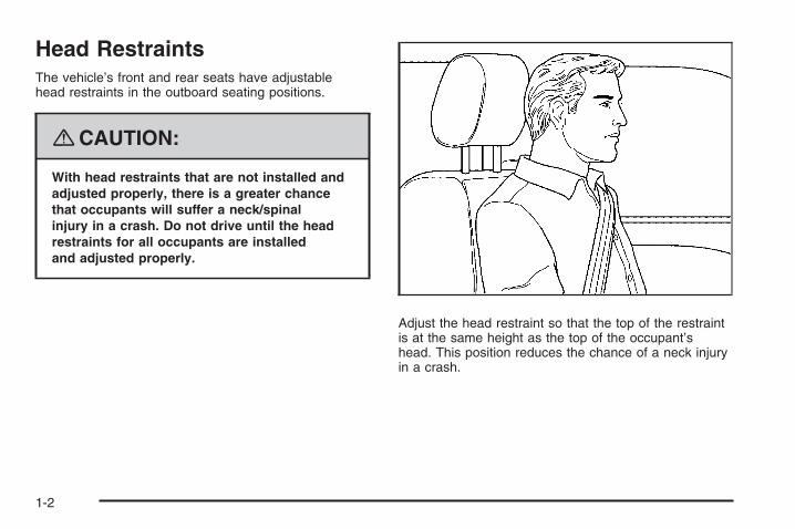
Head RestraintsThe vehicle’s front and rear seats have adjustablehead restraints in the outboard seating positions.
{CAUTION:
With head restraints that are not installed andadjusted properly, there is a greater chancethat occupants will suffer a neck/spinalinjury in a crash. Do not drive until the headrestraints for all occupants are installedand adjusted properly.
Adjust the head restraint so that the top of the restraintis at the same height as the top of the occupant’shead. This position reduces the chance of a neck injuryin a crash.
1-2
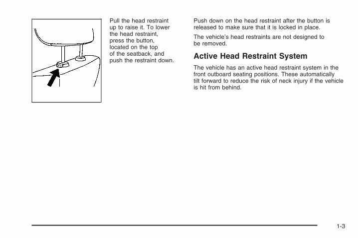
Pull the head restraintup to raise it. To lowerthe head restraint,press the button,located on the topof the seatback, andpush the restraint down.
Push down on the head restraint after the button isreleased to make sure that it is locked in place.
The vehicle’s head restraints are not designed tobe removed.
Active Head Restraint SystemThe vehicle has an active head restraint system in thefront outboard seating positions. These automaticallytilt forward to reduce the risk of neck injury if the vehicleis hit from behind.
1-3
Front Seats
Manual Seats
{CAUTION:
You can lose control of the vehicle if you try toadjust a manual driver’s seat while the vehicleis moving. The sudden movement could startleand confuse you, or make you push a pedalwhen you do not want to. Adjust the driver’sseat only when the vehicle is not moving.
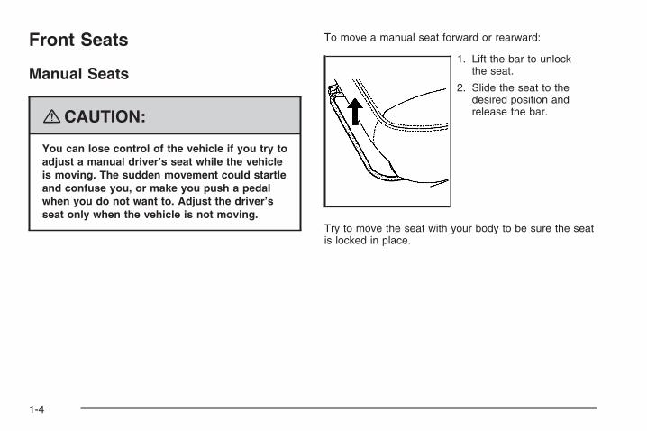
To move a manual seat forward or rearward:
1. Lift the bar to unlockthe seat.
2. Slide the seat to thedesired position andrelease the bar.
Try to move the seat with your body to be sure the seatis locked in place.
1-4
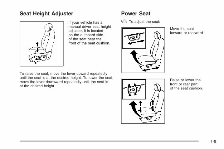
Seat Height Adjuster
If your vehicle has amanual driver seat heightadjuster, it is locatedon the outboard sideof the seat near thefront of the seat cushion.
To raise the seat, move the lever upward repeatedlyuntil the seat is at the desired height. To lower the seat,move the lever downward repeatedly until the seat isat the desired height.
Power Seata: To adjust the seat:
Move the seatforward or rearward.
Raise or lower thefront or rear partof the seat cushion.
1-5

Manual Lumbar
If your vehicle has thisfeature, the knob islocated on the inboardside of the driver’sseatback.
Turn the knob clockwise or counterclockwise to increaseor decrease the lumbar support.
Heated SeatsOn vehicles with heated front seats the controls arelocated on the center console. To operate the heatedseats the engine must be running.
M (Heated Seat): Press this button to turn on theheated seat.
The light on the button will come on to indicate that thefeature is working. Press the button to cycle throughthe temperature settings of high, medium, and low andto turn the heat to the seat off. Indicator lights showthe level of heat selected: three for high, two formedium, and one for low.
The passenger seat may take longer to heat up.
1-6

Manual Reclining Seatbacks
{CAUTION:
You can lose control of the vehicle if you try toadjust a manual driver’s seat while the vehicleis moving. The sudden movement could startleand confuse you, or make you push a pedalwhen you do not want to. Adjust the driver’sseat only when the vehicle is not moving.
{CAUTION:
If the seatback is not locked, it could moveforward in a sudden stop or crash. That couldcause injury to the person sitting there. Alwayspush and pull on the seatback to be sure it islocked.
To adjust the seatback, lift the lever on the outboardside of the seat and move the seatback to the desiredposition. Then release the lever to lock the seatbackin place. If the passenger’s seat is a flat foldingseat, fully raise the lever to disengage the seatback.
Driver’s Seat shown, Passenger Seat similar
1-7

{CAUTION:
Sitting in a reclined position when your vehicleis in motion can be dangerous. Even if youbuckle up, your safety belts cannot do theirjob when you are reclined like this.
The shoulder belt cannot do its job because itwill not be against your body. Instead, it willbe in front of you. In a crash, you could gointo it, receiving neck or other injuries.
The lap belt cannot do its job either. In acrash, the belt could go up over yourabdomen. The belt forces would be there,not at your pelvic bones. This could causeserious internal injuries.
For proper protection when the vehicle is inmotion, have the seatback upright. Then sitwell back in the seat and wear your safetybelt properly.
Do not have a seatback reclined if your vehicle is moving.
1-8
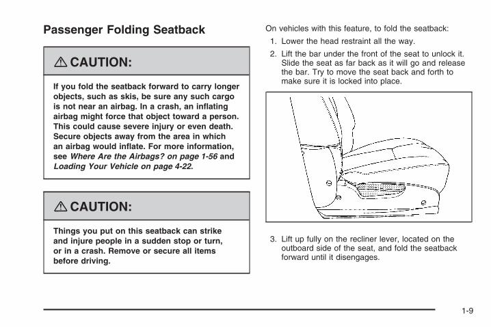
Passenger Folding Seatback
{CAUTION:
If you fold the seatback forward to carry longerobjects, such as skis, be sure any such cargois not near an airbag. In a crash, an inflatingairbag might force that object toward a person.This could cause severe injury or even death.Secure objects away from the area in whichan airbag would inflate. For more information,see Where Are the Airbags? on page 1-56 andLoading Your Vehicle on page 4-22.
{CAUTION:
Things you put on this seatback can strikeand injure people in a sudden stop or turn,or in a crash. Remove or secure all itemsbefore driving.
On vehicles with this feature, to fold the seatback:
1. Lower the head restraint all the way.
2. Lift the bar under the front of the seat to unlock it.Slide the seat as far back as it will go and releasethe bar. Try to move the seat back and forth tomake sure it is locked into place.
3. Lift up fully on the recliner lever, located on theoutboard side of the seat, and fold the seatbackforward until it disengages.
1-9

4. Continue to fold the seat forward until it locks inthe folded position.
5. Pull up on the seatback to be sure it is locked.
To raise the seatback, do the following:
1. Lift up fully on the recliner lever, located on theoutboard side of the seat, and push up on theseatback.
2. Continue raising the seatback until the seatbackre-engages.
{CAUTION:
If the seatback is not locked, it could moveforward in a sudden stop or crash. That couldcause injury to the person sitting there. Alwayspush and pull on the seatback to be sure it islocked.
3. Push and pull on the seatback to make sure it islocked in place.
The recliner lever is also used to recline the seatbackwhile a passenger is seated. See Manual RecliningSeatbacks on page 1-7.
Rear Seats
Split Folding Rear SeatThe rear split bench seatbacks can be folded forward,upright, or partially reclined, independent of theother seatback position.
1-10
{CAUTION:
If the seatback is not locked, it could moveforward in a sudden stop or crash. That couldcause injury to the person sitting there. Alwayspush and pull on the seatback to be sure it islocked.
{CAUTION:
A safety belt that is improperly routed, notproperly attached, or twisted will not providethe protection needed in a crash. The personwearing the belt could be seriously injured.After raising the rear seatback, always checkto be sure that the safety belts are properlyrouted and attached, and are not twisted.
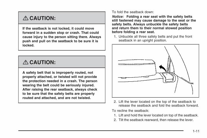
To fold the seatback down:Notice: Folding a rear seat with the safety beltsstill fastened may cause damage to the seat or thesafety belts. Always unbuckle the safety beltsand return them to their normal stowed positionbefore folding a rear seat.1. Unbuckle all three safety belts and put the front
seatback in an upright position.
2. Lift the lever located on the top of the seatback torelease the seatback and fold the seatback forward.
To recline the seatback:1. Lift and hold the lever located on top of the seatback.2. Tilt the seatback rearward, then release the lever.
1-11

Safety Belts
Safety Belts: They Are for EveryoneThis part of the manual tells you how to use safetybelts properly. It also tells you some things you shouldnot do with safety belts.
{CAUTION:
Do not let anyone ride where he or she cannotwear a safety belt properly. If you are in acrash and you are not wearing a safety belt,your injuries can be much worse. You can hitthings inside the vehicle harder or be ejectedfrom it and be seriously injured or killed.In the same crash, you might not be, if youare buckled up. Always fasten your safetybelt, and check that your passenger(s) arerestrained properly too.
{CAUTION:
It is extremely dangerous to ride in a cargoarea, inside or outside of a vehicle. In acollision, people riding in these areas are morelikely to be seriously injured or killed. Do notallow people to ride in any area of your vehiclethat is not equipped with seats and safetybelts. Be sure everyone in your vehicle is in aseat and using a safety belt properly.
Your vehicle has indicators as a reminder to buckle yoursafety belts. See Safety Belt Reminders on page 3-28.
In most states and in all Canadian provinces, thelaw requires wearing safety belts. Here is why:
You never know if you will be in a crash. If you do havea crash, you do not know if it will be a serious one.
A few crashes are mild, and some crashes can be soserious that even buckled up, a person would not survive.But most crashes are in between. In many of them, peoplewho buckle up can survive and sometimes walk away.Without belts they could have been badly hurt or killed.
After more than 40 years of safety belts in vehicles,the facts are clear. In most crashes buckling up doesmatter... a lot!
1-12

Why Safety Belts WorkWhen you ride in or on anything, you go as fast as it goes.
Take the simplest vehicle. Suppose it is just a seaton wheels.
Put someone on it.
1-13

Get it up to speed. Then stop the vehicle.The rider does not stop.
The person keeps going until stopped by something.In a real vehicle, it could be the windshield...
1-14

or the instrument panel... or the safety belts!
With safety belts, you slow down as the vehicle does.You get more time to stop. You stop over more distance,and your strongest bones take the forces. That is whysafety belts make such good sense.
1-15
Questions and Answers AboutSafety Belts
Q: Will I be trapped in the vehicle after a crashif I am wearing a safety belt?
A: You could be — whether you are wearing a safetybelt or not. But your chance of being consciousduring and after an accident, so you can unbuckleand get out, is much greater if you are belted.And you can unbuckle a safety belt, even if youare upside down.
Q: If my vehicle has airbags, why should I haveto wear safety belts?
A: Airbags are supplemental systems only; so theywork with safety belts — not instead of them.Whether or not an airbag is provided, all occupantsstill have to buckle up to get the most protection.That is true not only in frontal collisions, butespecially in side and other collisions.
Q: If I am a good driver, and I never drive far fromhome, why should I wear safety belts?
A: You may be an excellent driver, but if you are ina crash — even one that is not your fault — youand your passenger(s) can be hurt. Being agood driver does not protect you from thingsbeyond your control, such as bad drivers.
Most accidents occur within 25 miles (40 km)of home. And the greatest number of seriousinjuries and deaths occur at speeds of lessthan 40 mph (65 km/h).
Safety belts are for everyone.
1-16

How to Wear Safety Belts ProperlyThis section is only for people of adult size.
Be aware that there are special things to know aboutsafety belts and children. And there are differentrules for smaller children and babies. If a child will beriding in your vehicle, see Older Children on page 1-31or Infants and Young Children on page 1-34. Followthose rules for everyone’s protection.
It is very important for all occupants to buckle up.Statistics show that unbelted people are hurt more oftenin crashes than those who are wearing safety belts.
Occupants who are not buckled up can be thrown out ofthe vehicle in a crash. And they can strike others inthe vehicle who are wearing safety belts.
First, before you or your passenger(s) wear a safetybelt, there is important information you should know. Sit up straight and always keep your feet on the floor in
front of you. The lap part of the belt should be worn lowand snug on the hips, just touching the thighs. In a crash,this applies force to the strong pelvic bones and youwould be less likely to slide under the lap belt. If you slidunder it, the belt would apply force on your abdomen.This could cause serious or even fatal injuries. Theshoulder belt should go over the shoulder and across thechest. These parts of the body are best able to take beltrestraining forces.The shoulder belt locks if there is a sudden stop or crash.
1-17
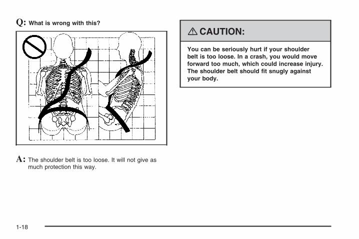
Q: What is wrong with this?
A: The shoulder belt is too loose. It will not give asmuch protection this way.
{CAUTION:
You can be seriously hurt if your shoulderbelt is too loose. In a crash, you would moveforward too much, which could increase injury.The shoulder belt should fit snugly againstyour body.
1-18

Q: What is wrong with this?
A: The lap belt is too loose. It will not give nearly asmuch protection this way.
{CAUTION:
You can be seriously hurt if your lap belt istoo loose. In a crash, you could slide underthe lap belt and apply force on your abdomen.This could cause serious or even fatal injuries.The lap belt should be worn low and snugon the hips, just touching the thighs.
1-19

Q: What is wrong with this?
A: The belt is buckled in the wrong place.
{CAUTION:
You can be seriously injured if your belt isbuckled in the wrong place like this. In a crash,the belt would go up over your abdomen.The belt forces would be there, not on thepelvic bones. This could cause serious internalinjuries. Always buckle your belt into thebuckle nearest you.
1-20

Q: What is wrong with this?
A: The belt is over an armrest.
{CAUTION:
You can be seriously injured if your belt goesover an armrest like this. The belt would bemuch too high. In a crash, you can slide underthe belt. The belt force would then be appliedon the abdomen, not on the pelvic bones,and that could cause serious or fatal injuries.Be sure the belt goes under the armrests.
1-21

Q: What is wrong with this?
A: The shoulder belt is worn under the arm.It should be worn over the shoulder at all times.
{CAUTION:
You can be seriously injured if you wear theshoulder belt under your arm. In a crash, yourbody would move too far forward, which wouldincrease the chance of head and neck injury.Also, the belt would apply too much force tothe ribs, which are not as strong as shoulderbones. You could also severely injure internalorgans like your liver or spleen. The shoulderbelt should go over the shoulder and acrossthe chest.
1-22

Q: What is wrong with this?
A: The belt is behind the body.
{CAUTION:
You can be seriously injured by not wearingthe lap-shoulder belt properly. In a crash,you would not be restrained by the shoulderbelt. Your body could move too far forwardincreasing the chance of head and neck injury.You might also slide under the lap belt. Thebelt force would then be applied right on theabdomen. That could cause serious or fatalinjuries. The shoulder belt should go overthe shoulder and across the chest.
1-23

Q: What is wrong with this?
A: The belt is twisted across the body.
{CAUTION:
You can be seriously injured by a twisted belt.In a crash, you would not have the full widthof the belt to spread impact forces. If a beltis twisted, make it straight so it can workproperly, or ask your dealer/retailer to fix it.
1-24

Lap-Shoulder BeltAll seating positions in your vehicle have alap-shoulder belt.
Here is how to wear a lap-shoulder belt properly.
1. Adjust the seat, if the seat is adjustable, so youcan sit up straight. To see how, see “Seats” inthe Index.
2. Pick up the latch plate and pull the belt across you.Do not let it get twisted.The lap-shoulder belt may lock if you pull the beltacross you very quickly. If this happens, let thebelt go back slightly to unlock it. Then pull the beltacross you more slowly.If you ever pull the shoulder portion of a passengerbelt out all the way, you may engage the childrestraint locking feature. If this happens, just letthe belt go back all the way and start again.Engaging the child restraint locking featuremay affect the passenger sensing system.See Passenger Sensing System on page 1-63.
3. Push the latch plate into the buckle until it clicks.Pull up on the latch plate to make sure it is secure.If the belt is not long enough, see Safety BeltExtender on page 1-30.Make sure the release button on the buckle ispositioned so you would be able to unbuckle thesafety belt quickly if necessary.
4. If equipped with a shoulder belt height adjuster,move it to the height that is right for you. Impropershoulder belt height adjustment could reducethe effectiveness of the safety belt in a crash.See “Shoulder Belt Height Adjustment” later inthis section.
1-25

5. To make the lap part tight, pull up on theshoulder belt.It may be necessary to pull stitching on thesafety belt through the latch plate to fullytighten the lap belt on smaller occupants.
To unlatch the belt, just push the button on the buckle.The belt should go back out of the way. When thesafety belt is not in use, slide the latch plate upthe safety belt webbing. The latch plate should reston the stitching on the safety belt, near the guideloop on the side wall.
Before you close a door, be sure the belt is out ofthe way. If you slam the door on it, you can damageboth the belt and your vehicle.
1-26

Shoulder Belt Height AdjusterYour vehicle has a shoulder belt height adjuster forthe driver and right front passenger.
Adjust the height so that the shoulder portion of thebelt is centered on your shoulder. The belt shouldbe away from your face and neck, but not fallingoff your shoulder. Improper shoulder belt heightadjustment could reduce the effectiveness of thesafety belt in a crash.
To move it up or down,squeeze the releasebuttons (A) togetherand move the heightadjuster to thedesired position.
After you move the height adjuster to where youwant it, try to move it up or down without squeezingthe release buttons to make sure it has locked intoposition.
Safety Belt PretensionersYour vehicle has safety belt pretensioners for frontoutboard occupants. Although you cannot see them,they are part of the safety belt assembly. They canhelp tighten the safety belts during the early stages ofa moderate to severe frontal, near frontal, or rear crashif the threshold conditions for pretensioner activationare met. And, if your vehicle has side impact airbags,safety belt pretensioners can help tighten the safetybelts in a side crash or a rollover event.
Pretensioners work only once. If they activate in acrash, you will need to get new ones, and probably othernew parts for your safety belt system. See ReplacingRestraint System Parts After a Crash on page 1-71.
1-27
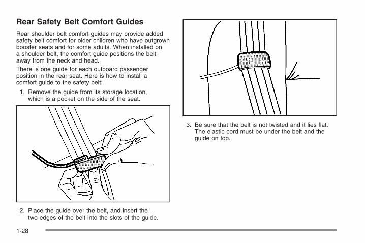
Rear Safety Belt Comfort GuidesRear shoulder belt comfort guides may provide addedsafety belt comfort for older children who have outgrownbooster seats and for some adults. When installed ona shoulder belt, the comfort guide positions the beltaway from the neck and head.There is one guide for each outboard passengerposition in the rear seat. Here is how to install acomfort guide to the safety belt:
1. Remove the guide from its storage location,which is a pocket on the side of the seat.
2. Place the guide over the belt, and insert thetwo edges of the belt into the slots of the guide.
3. Be sure that the belt is not twisted and it lies flat.The elastic cord must be under the belt and theguide on top.
1-28

{CAUTION:
A safety belt that is not properly worn maynot provide the protection needed in a crash.The person wearing the belt could be seriouslyinjured. The shoulder belt should go over theshoulder and across the chest. These parts ofthe body are best able to take belt restrainingforces.
4. Buckle, position, and release the safety belt asdescribed previously in this section. Make surethat the shoulder belt crosses the shoulder.
To remove and store the comfort guide, squeeze thebelt edges together so that you can take them out of theguide. Store the comfort guide in its storage location,which is a pocket on the side of the seat.
1-29

Safety Belt Use During PregnancySafety belts work for everyone, including pregnantwomen. Like all occupants, they are more likely to beseriously injured if they do not wear safety belts.
A pregnant woman should wear a lap-shoulder belt,and the lap portion should be worn as low as possible,below the rounding, throughout the pregnancy.
The best way to protect the fetus is to protect themother. When a safety belt is worn properly, it is morelikely that the fetus will not be hurt in a crash. Forpregnant women, as for anyone, the key to makingsafety belts effective is wearing them properly.
Safety Belt ExtenderIf the safety belt will fasten around you, you should use it.
But if a safety belt is not long enough, your dealer/retailerwill order you an extender. When you go in to order it,take the heaviest coat you will wear, so the extender willbe long enough for you. To help avoid personal injury,do not let someone else use it, and use it only for the seatit is made to fit. The extender has been designed foradults. Never use it for securing child seats. To wear it,attach it to the regular safety belt. For more information,see the instruction sheet that comes with the extender.
1-30

Child Restraints
Older Children
Older children who have outgrown booster seats shouldwear the vehicle’s safety belts.
The manufacturer’s instructions that come with thebooster seat state the weight and height limitations forthat booster. Use a booster seat with a lap-shoulderbelt until the child passes the below fit test:
• Sit all the way back on the seat. Do the kneesbend at the seat edge? If yes, continue.If no, return to the booster seat.
• Buckle the lap-shoulder belt. Does the shoulderbelt rest on the shoulder? If yes, continue.If no, try using the rear safety belt comfort guide.See “Rear Safety Belt Comfort Guides” underLap-Shoulder Belt on page 1-25 for moreinformation. If the shoulder belt still does not reston the shoulder, then return to the booster seat.
• Does the lap belt fit low and snug on the hips,touching the thighs? If yes, continue.If no, return to the booster seat.
• Can proper safety belt fit be maintained forthe length of the trip? If yes, continue.If no, return to the booster seat.
1-31

Q: What is the proper way to wear safety belts?
A: An older child should wear a lap-shoulder belt andget the additional restraint a shoulder belt canprovide. The shoulder belt should not cross the faceor neck. The lap belt should fit snugly below thehips, just touching the top of the thighs. This appliesbelt force to the child’s pelvic bones in a crash.It should never be worn over the abdomen, whichcould cause severe or even fatal internal injuriesin a crash.
Also see “Rear Safety Belt Comfort Guides” underLap-Shoulder Belt on page 1-25.
According to accident statistics, children and infantsare safer when properly restrained in the rear seatingpositions than in the front seating positions.
In a crash, children who are not buckled up can strikeother people who are buckled up, or can be thrownout of the vehicle. Older children need to use safetybelts properly.
{CAUTION:
Never do this.
Here two children are wearing the same belt.The belt cannot properly spread the impactforces. In a crash, the two children can becrushed together and seriously injured. A beltmust be used by only one person at a time.
1-32

{CAUTION:
Never do this.
Here a child is sitting in a seat that has alap-shoulder belt, but the shoulder part isbehind the child. In a crash, the child wouldnot be restrained by the shoulder belt. Thechild might slide under the lap belt. The beltforce would then be applied right on theabdomen. That could cause serious or fatalinjuries. The child could also move too farforward increasing the chance of head andneck injury. The shoulder belt should goover the shoulder and across the chest.
1-33

Infants and Young ChildrenEveryone in a vehicle needs protection! This includesinfants and all other children. Neither the distancetraveled nor the age and size of the traveler changesthe need, for everyone, to use safety restraints.In fact, the law in every state in the United Statesand in every Canadian province says children up tosome age must be restrained while in a vehicle.
{CAUTION:
Children can be seriously injured or strangledif a shoulder belt is wrapped around theirneck and the safety belt continues to tighten.Never leave children unattended in a vehicleand never allow children to play with thesafety belts.
Every time infants and young children ride in vehicles,they should have the protection provided by appropriaterestraints. Children who are not restrained properlycan strike other people, or can be thrown out ofthe vehicle. In addition, young children should notuse the vehicle’s adult safety belts alone; they needto use a child restraint.
{CAUTION:
People should never hold an infant in theirarms while riding in a vehicle. An infant doesnot weigh much — until a crash. During acrash an infant will become so heavy it isnot possible to hold it. For example, in acrash at only 25 mph (40 km/h), a 12 lb (5.5 kg)infant will suddenly become a 240 lb (110 kg)force on a person’s arms. An infant shouldbe secured in an appropriate restraint.
1-34

{CAUTION:
Children who are up against, or very close to,any airbag when it inflates can be seriouslyinjured or killed. Airbags plus lap-shoulder beltsoffer protection for adults and older children,but not for young children and infants.
CAUTION: (Continued)
CAUTION: (Continued)
Neither the vehicle’s safety belt system norits airbag system is designed for them. Youngchildren and infants need the protection thata child restraint system can provide.
1-35

Q: What are the different types of add-on childrestraints?
A: Add-on child restraints, which are purchased by thevehicle’s owner, are available in four basic types.Selection of a particular restraint should takeinto consideration not only the child’s weight, height,and age but also whether or not the restraint willbe compatible with the motor vehicle in which itwill be used.
For most basic types of child restraints, there aremany different models available. When purchasinga child restraint, be sure it is designed to beused in a motor vehicle. If it is, the restraint willhave a label saying that it meets federal motorvehicle safety standards.
The restraint manufacturer’s instructions thatcome with the restraint state the weight andheight limitations for a particular child restraint.In addition, there are many kinds of restraintsavailable for children with special needs.
{CAUTION:
Newborn infants need complete support,including support for the head and neck.This is necessary because a newborn infant’sneck is weak and its head weighs so muchcompared with the rest of its body. In a crash,an infant in a rear-facing seat settles intothe restraint, so the crash forces can bedistributed across the strongest part of aninfant’s body, the back and shoulders.Infants should always be secured inappropriate infant restraints.
1-36
{CAUTION:
The body structure of a young child is quiteunlike that of an adult or older child, for whomthe safety belts are designed. A young child’ship bones are still so small that the vehicle’sregular safety belt may not remain low on thehip bones, as it should. Instead, it may settleup around the child’s abdomen. In a crash,the belt would apply force on a body areathat is unprotected by any bony structure.This alone could cause serious or fatal injuries.Young children should always be secured inappropriate child restraints.
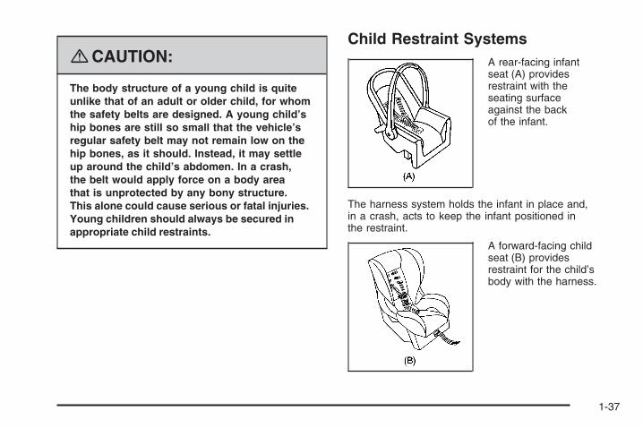
Child Restraint SystemsA rear-facing infantseat (A) providesrestraint with theseating surfaceagainst the backof the infant.
The harness system holds the infant in place and,in a crash, acts to keep the infant positioned inthe restraint.
A forward-facing childseat (B) providesrestraint for the child’sbody with the harness.
1-37

A booster seat (C-D) is a child restraint designed toimprove the fit of the vehicle’s safety belt system.A booster seat can also help a child to see outthe window.
Securing an Add-On Child Restraintin the Vehicle
{CAUTION:
A child can be seriously injured or killed ina crash if the child restraint is not properlysecured in the vehicle. Make sure the childrestraint is properly installed in the vehicleusing the vehicle’s safety belt or LATCHsystem, following the instructions that camewith that restraint, and also the instructionsin this manual.
1-38

To help reduce the chance of injury, the child restraintmust be secured in the vehicle. Child restraint systemsmust be secured in vehicle seats by lap belts or thelap belt portion of a lap-shoulder belt, or by the LATCHsystem. See Lower Anchors and Tethers for Children(LATCH) on page 1-41 for more information. A child canbe endangered in a crash if the child restraint is notproperly secured in the vehicle.
When securing an add-on child restraint, refer to theinstructions that come with the restraint which may be onthe restraint itself or in a booklet, or both, and to thismanual. The child restraint instructions are important,so if they are not available, obtain a replacementcopy from the manufacturer.
Keep in mind that an unsecured child restraint canmove around in a collision or sudden stop and injurepeople in the vehicle. Be sure to properly secureany child restraint in your vehicle — even when nochild is in it.
Securing the Child Within theChild Restraint
{CAUTION:
A child can be seriously injured or killed ina crash if the child is not properly securedin the child restraint. Because there aredifferent systems, it is important to refer tothe instructions that come with the restraint.Make sure the child is properly secured,following the instructions that came withthat restraint.
Where to Put the RestraintAccident statistics show that children are safer if theyare restrained in the rear rather than the front seat.
We recommend that children and child restraintsbe secured in a rear seat, including: an infant or achild riding in a rear-facing child restraint; a child ridingin a forward-facing child seat; an older child riding ina booster seat; and children, who are large enough,using safety belts.
1-39

A label on the sun visor says, “Never put a rear-facingchild seat in the front.” This is because the risk tothe rear-facing child is so great, if the airbag deploys.
{CAUTION:
A child in a rear-facing child restraint can beseriously injured or killed if the right frontpassenger’s airbag inflates. This is becausethe back of the rear-facing child restraintwould be very close to the inflating airbag.
Even if the passenger sensing system hasturned off the right front passenger’s frontalairbag, no system is fail-safe. No one canguarantee that an airbag will not deployunder some unusual circumstance, eventhough it is turned off. Rear-facing childrestraints should be secured in a rear seat,even if the airbag is off.
CAUTION: (Continued)
CAUTION: (Continued)
If you secure a forward-facing child restraintin the right front seat, always move the frontpassenger seat as far back as it will go.It is better to secure the child restraint ina rear seat.
See Passenger Sensing System on page 1-63for additional information.
If the vehicle does not have a rear seat that willaccommodate a rear-facing child restraint, a rear-facingchild restraint should not be installed in the vehicle,even if the airbag is off.
When securing a child restraint in a rear seatingposition, study the instructions that came with your childrestraint to make sure it is compatible with this vehicle.
Wherever you install a child restraint, be sure tosecure the child restraint properly.
Keep in mind that an unsecured child restraint can movearound in a collision or sudden stop and injure peoplein the vehicle. Be sure to properly secure any childrestraint in your vehicle — even when no child is in it.
1-40
Lower Anchors and Tethers forChildren (LATCH)The LATCH system holds a child restraint during drivingor in a crash. This system is designed to make installationof a child restraint easier. The LATCH system usesanchors in the vehicle and attachments on the childrestraint that are made for use with the LATCH system.
Make sure that a LATCH-compatible child restraint isproperly installed using the anchors, or use the vehicle’ssafety belts to secure the restraint, following theinstructions that came with that restraint, and also theinstructions in this manual. When installing a childrestraint with a top tether, you must also use either thelower anchors or the safety belts to properly secure thechild restraint. A child restraint must never be installedusing only the top tether and anchor.
In order to use the LATCH system in your vehicle,you need a child restraint that has LATCH attachments.The child restraint manufacturer will provide you withinstructions on how to use the child restraint and itsattachments. The following explains how to attach achild restraint with these attachments in your vehicle.
Not all vehicle seating positions or child restraints havelower anchors and attachments or top tether anchorsand attachments.
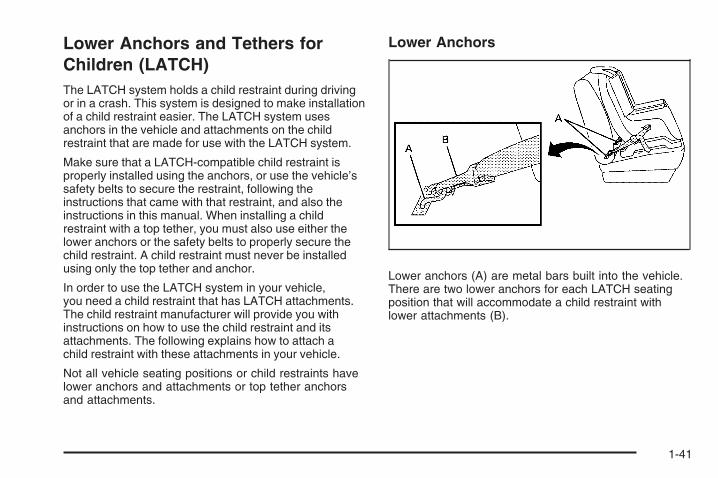
Lower Anchors
Lower anchors (A) are metal bars built into the vehicle.There are two lower anchors for each LATCH seatingposition that will accommodate a child restraint withlower attachments (B).
1-41

Top Tether Anchor
A top tether (A, C) anchors the top of the child restraintto the vehicle. A top tether anchor is built into thevehicle. The top tether attachment (B) on the childrestraint connects to the top tether anchor in the vehiclein order to reduce the forward movement and rotationof the child restraint during driving or in a crash.
Your child restraint may have a single tether (A) or adual tether (C). Either will have a single attachment (B)to secure the top tether to the anchor.
Some child restraints that have top tethers are designedfor use with or without the top tether being attached.Others require the top tether always to be attached.In Canada, the law requires that forward-facingchild restraints have a top tether, and that the tetherbe attached. Be sure to read and follow the instructionsfor your child restraint.
If the child restraint does not have a top tether, onecan be obtained, in kit form, for many child restraints.Ask the child restraint manufacturer whether or nota kit is available.
Lower Anchor and Top Tether AnchorLocations
i (Top Tether Anchor):Seating positions withtop tether anchors.
j (Lower Anchor):Seating positions withtwo lower anchors.
Rear Seat
1-42

To assist you in locatingthe lower anchors, eachseating position with loweranchors has two labels,near the crease betweenthe seatback and theseat cushion.
To assist you in locatingthe top tether anchors, thetop tether anchor symbolis located near the toptether anchors.
The top tether anchors are located on the back of therear seatback. Be sure to use an anchor located onthe same side of the vehicle as the seating positionwhere the child restraint will be placed.
Do not secure a child restraint in a position without atop tether anchor if a national or local law requires thatthe top tether be attached, or if the instructions thatcome with the child restraint say that the top tethermust be attached.
Accident statistics show that children are safer if theyare restrained in the rear rather than the front seat.See Where to Put the Restraint on page 1-39 foradditional information.
1-43

Securing a Child Restraint Designed forthe LATCH System
{CAUTION:
If a LATCH-type child restraint is not attachedto anchors, the restraint will not be able toprotect the child correctly. In a crash, thechild could be seriously injured or killed.Make sure that a LATCH-type child restraintis properly installed using the anchors,or use the vehicle’s safety belts to securethe restraint, following the instructionsthat came with that restraint, and also theinstructions in this manual.
{CAUTION:
Each top tether anchor and lower anchor inthe vehicle is designed to hold only one childrestraint. Attaching more than one childrestraint to a single anchor could cause theanchor or attachment to come loose or evenbreak during a crash. A child or others couldbe injured if this happens. To help preventinjury to people and damage to your vehicle,attach only one child restraint per anchor.
1-44

{CAUTION:
Children can be seriously injured or strangledif a shoulder belt is wrapped around theirneck and the safety belt continues to tighten.Secure any unused safety belts behind thechild restraint so children cannot reach them.Pull the shoulder belt all the way out of theretractor to set the lock, if your vehicle hasone, after the child restraint has been installed.Be sure to follow the instructions of thechild restraint manufacturer.
Notice: Contact between the child restraint LATCHattachment parts and the vehicle’s safety beltassembly may cause damage to these parts. Makesure when securing unused safety belts behindthe child restraint that there is no contact betweenthe child restraint LATCH attachment parts andthe vehicle’s safety belt assembly.
Folding an empty rear seat with the safety beltssecured may cause damage to the safety belt orthe seat. When removing the child restraint,always remember to return the safety belts totheir normal, stowed position before foldingthe rear seat.
1. Attach and tighten the lower attachments to thelower anchors. If the child restraint does not havelower attachments or the desired seating positiondoes not have lower anchors, secure the childrestraint with the top tether and the safety belts.Refer to your child restraint manufacturerinstructions and the instructions in this manual.
1.1. Find the lower anchors for the desiredseating position.
1.2. Put the child restraint on the seat.1.3. Attach and tighten the lower attachments
on the child restraint to the lower anchors.
1-45

2. If the child restraint manufacturer recommends thatthe top tether be attached, attach and tighten thetop tether to the top tether anchor, if equipped.Refer to the child restraint instructions andthe following steps:
2.1. Find the top tether anchor.2.2. Route, attach, and tighten the top tether
according to your child restraint instructionsand the following instructions:
If the position you areusing does not have aheadrest or head restraintand you are using asingle tether, route thetether over the seatback.
If the position you areusing does not have aheadrest or head restraintand you are using adual tether, route the tetherover the seatback.
If the position you areusing has an adjustableheadrest or head restraintand you are using adual tether, route the tetheraround the headrest orhead restraint.
1-46

If the position you areusing has an adjustableheadrest or head restraintand you are using asingle tether, raise theheadrest or head restraintand route the tetherunder the headrest or headrestraint and in betweenthe headrest or headrestraint posts.
3. Push and pull the child restraint in differentdirections to be sure it is secure.
Securing a Child Restraint in aRear Seat PositionWhen securing a child restraint in a rear seatingposition, study the instructions that came with your childrestraint to make sure it is compatible with this vehicle.
If your child restraint has the LATCH system, seeLower Anchors and Tethers for Children (LATCH)on page 1-41 for how and where to install your childrestraint using LATCH. If you secure a child restraintusing a safety belt and it uses a top tether, seeLower Anchors and Tethers for Children (LATCH)on page 1-41 for top tether anchor locations.
Do not secure a child restraint in a position without atop tether anchor if a national or local law requires thatthe top tether be anchored, or if the instructions thatcome with the child restraint say that the top strap mustbe anchored.
In Canada, the law requires that forward-facing childrestraints have a top tether, and that the tether beattached.
If your child restraint does not have the LATCHsystem, you will be using the safety belt to securethe child restraint in this position. Be sure to followthe instructions that came with the child restraint.Secure the child in the child restraint when andas the instructions say.
1-47

If you need to install more than one child restraint in therear seat, be sure to read Where to Put the Restrainton page 1-39.
1. Put the child restraint on the seat.2. Pick up the latch plate, and run the lap and shoulder
portions of the vehicle’s safety belt through oraround the restraint. The child restraint instructionswill show you how.
3. Push the latch plate into the buckle until it clicks.Make sure the release button is positioned so youwould be able to unbuckle the safety belt quicklyif necessary.
4. Pull the rest of the shoulder belt all the way out ofthe retractor to set the lock.
1-48

5. To tighten the belt, push down on the child restraint,pull the shoulder portion of the belt to tighten thelap portion of the belt, and feed the shoulderbelt back into the retractor. If you are using aforward-facing child restraint, you may find ithelpful to use your knee to push down on thechild restraint as you tighten the belt.
6. If your child restraint has a top tether, follow thechild restraint manufacturer’s instructions regardingthe use of the top tether. See Lower Anchorsand Tethers for Children (LATCH) on page 1-41for more information.
7. Push and pull the child restraint in differentdirections to be sure it is secure.
To remove the child restraint, unbuckle the vehiclesafety belt and let it return to the stowed position.If the top tether is attached to a top tether anchor,disconnect it.
Securing a Child Restraint in theRight Front Seat PositionYour vehicle has airbags. A rear seat is a safer placeto secure a forward-facing child restraint. See Whereto Put the Restraint on page 1-39.
In addition, your vehicle has a passenger sensingsystem which is designed to turn off the right frontpassenger’s frontal airbag under certain conditions.See Passenger Sensing System on page 1-63and Passenger Airbag Status Indicator on page 3-30for more information on this, including importantsafety information.
1-49

A label on your sun visor says, “Never put a rear-facingchild seat in the front.” This is because the risk to therear-facing child is so great, if the airbag deploys.
{CAUTION:
A child in a rear-facing child restraint can beseriously injured or killed if the right frontpassenger’s airbag inflates. This is becausethe back of the rear-facing child restraintwould be very close to the inflating airbag.
Even if the passenger sensing system hasturned off the right front passenger’s frontalairbag, no system is fail-safe. No one canguarantee that an airbag will not deploy undersome unusual circumstance, even thoughit is turned off. Rear-facing child restraintsshould be secured in a rear seat, even ifthe airbag is off.
CAUTION: (Continued)
CAUTION: (Continued)
If you secure a forward-facing child restraintin the right front seat, always move thefront passenger seat as far back as it will go.It is better to secure the child restraint in arear seat.
See Passenger Sensing System on page 1-63for additional information.
If your vehicle does not have a rear seat that willaccommodate a rear-facing child restraint, werecommend that rear-facing child restraints not betransported in your vehicle, even if the airbag is off.
If your child restraint has the LATCH system, seeLower Anchors and Tethers for Children (LATCH)on page 1-41 for how to install your child restraint usingLATCH. If you secure a child restraint using a safetybelt and it uses a top tether, see Lower Anchorsand Tethers for Children (LATCH) on page 1-41for top tether anchor locations.
1-50

Do not secure a child seat in a position without a toptether anchor if a national or local law requires thatthe top tether be anchored, or if the instructionsthat come with the child restraint say that the topstrap must be anchored.
In Canada, the law requires that forward-facing childrestraints have a top tether, and that the tether beattached.
You will be using the lap-shoulder belt to secure thechild restraint in this position. Follow the instructionsthat came with the child restraint.
1. Move the seat as far back as it will go beforesecuring the forward-facing child restraint.When the passenger sensing system has turnedoff the right front passenger’s frontal airbag, the offindicator on the passenger airbag status indicatorshould light and stay lit when you start the vehicle.See Passenger Airbag Status Indicator onpage 3-30.
2. Put the child restraint on the seat.
3. Pick up the latch plate, and run the lap andshoulder portions of the vehicle’s safety beltthrough or around the restraint. The childrestraint instructions will show you how.
4. Push the latch plate into the buckle until it clicks.Make sure the release button is positioned soyou would be able to unbuckle the safety beltquickly if necessary.
1-51

5. Pull the rest of the shoulder belt all the way out ofthe retractor to set the lock.
6. To tighten the belt, push down on the child restraint,pull the shoulder portion of the belt to tighten thelap portion of the belt and feed the shoulderbelt back into the retractor. If you are using aforward-facing child restraint, you may find it helpfulto use your knee to push down on the childrestraint as you tighten the belt.
7. If your vehicle does not have a rear seat and yourchild restraint has a top tether, follow the childrestraint manufacturer’s instructions regarding theuse of the top tether. See Lower Anchors andTethers for Children (LATCH) on page 1-41 formore information.
8. Push and pull the child restraint in differentdirections to be sure it is secure.
1-52

If the airbag is off, the off indicator in the passengerairbag status indicator will come on and stay on whenthe vehicle is started.
If a child restraint has been installed and the onindicator is lit, turn the vehicle off. Remove the childrestraint from the vehicle and reinstall the child restraint.
If, after reinstalling the child restraint and restartingthe vehicle, the on indicator is still lit, check to makesure that the vehicle’s seatback is not pressing the childrestraint into the seat cushion. If this happens, slightlyrecline the vehicle’s seatback and adjust the seatcushion if possible. Also make sure the child restraintis not trapped under the vehicle head restraint.If this happens, adjust the head restraint.
Remove any additional material from the seat suchas blankets, cushions, seat covers, seat heaters orseat massagers before reinstalling or securing thechild restraint.
If the on indicator is still lit, secure the child in thechild restraint in a rear seat position in the vehicleand check with your dealer/retailer. If no rear seat isavailable, do not install a child restraint in this vehicleand check with your dealer/retailer.
To remove the child restraint, unbuckle the vehicle’ssafety belt and let it go back all the way. If the toptether is attached to a top tether anchor, disconnect it.
Airbag SystemYour vehicle has the following airbags:
• A frontal airbag for the driver.
• A frontal airbag for the right front passenger.
• A seat-mounted side impact airbag for the driver.
• A seat-mounted side impact airbag for theright front passenger.
• A roof-rail airbag for the driver and the passengerseated directly behind the driver.
• A roof-rail airbag for the right front passengerand the passenger seated directly behind theright front passenger.
All of the airbags in your vehicle will have the wordAIRBAG embossed in the trim or on an attached labelnear the deployment opening.
For frontal airbags, the word AIRBAG will appear onthe middle part of the steering wheel for the driver andon the instrument panel for the right front passenger.
With seat-mounted side impact airbags, the wordAIRBAG will appear on the side of the seatbackclosest to the door.
With roof-rail airbags, the word AIRBAG will appearalong the headliner or trim.
1-53

If your vehicle does not have a right front passenger seat,the frontal passenger airbag is disabled. The frontalpassenger airbag is still in the vehicle, but it should notdeploy in a crash. Even if the airbag is disabled, do notplace cargo in front of this or any airbag.
{CAUTION:
Be sure that cargo is not near an airbag.In a crash, an inflating airbag might forcethat object toward a person. This could causesevere injury or even death. Secure objectsaway from the area in which an airbag wouldinflate. For more information, see WhereAre the Airbags? on page 1-56 and LoadingYour Vehicle on page 4-22.
Airbags are designed to supplement the protectionprovided by safety belts. Even though today’s airbagsare also designed to help reduce the risk of injuryfrom the force of an inflating bag, all airbags mustinflate very quickly to do their job.
Here are the most important things to know about theairbag system:
{CAUTION:
You can be severely injured or killed in a crashif you are not wearing your safety belt — evenif you have airbags. Wearing your safety beltduring a crash helps reduce your chance ofhitting things inside the vehicle or beingejected from it. Airbags are “supplementalrestraints” to the safety belts. All airbags aredesigned to work with safety belts, but donot replace them.
1-54

{CAUTION:
Frontal airbags are designed to deploy inmoderate to severe frontal and near frontalcrashes. They are not designed to inflate inrollover, rear crashes, or in many side crashes.
Seat-mounted side impact airbags aredesigned to inflate in moderate to severecrashes where something hits the side ofyour vehicle. They are not designed to inflatein frontal, in rollover, or in rear crashes.Rollover capable roof-rail airbags are designedto inflate in moderate to severe crasheswhere something hits the side of your vehicle,during a vehicle rollover, or in a severe frontalimpact. They are not designed to inflate inrear crashes.
Everyone in your vehicle should wear a safetybelt properly — whether or not there is anairbag for that person.
{CAUTION:
Airbags inflate with great force, faster thanthe blink of an eye. Anyone who is up against,or very close to, any airbag when it inflatescan be seriously injured or killed. Do not situnnecessarily close to the airbag, as youwould be if you were sitting on the edge ofyour seat or leaning forward. Safety beltshelp keep you in position before and duringa crash. Always wear your safety belt, evenwith airbags. The driver should sit as far backas possible while still maintaining controlof the vehicle.
Occupants should not lean on or sleep againstthe door or side windows in seating positionswith seat-mounted side impact airbags and/orroof-rail airbags.
1-55

{CAUTION:
Airbags plus lap-shoulder belts offer thebest protection for adults, but not for youngchildren and infants. Neither the vehicle’ssafety belt system nor its airbag system isdesigned for them. Young children and infantsneed the protection that a child restraintsystem can provide. Always secure childrenproperly in your vehicle. To read how, seeOlder Children on page 1-31 or Infants andYoung Children on page 1-34.
There is an airbagreadiness light onthe instrument panelcluster, which showsthe airbag symbol.
The system checks the airbag electrical system formalfunctions. The light tells you if there is an electricalproblem. See Airbag Readiness Light on page 3-29for more information.
Where Are the Airbags?
The driver’s frontal airbag is in the middle of thesteering wheel.
1-56

The right front passenger’s frontal airbag is in theinstrument panel on the passenger’s side. The seat-mounted side impact airbags for the driver and
right front passenger are in the side of the seatbacksclosest to the door.
Driver Side shown, Passenger Side similar
1-57

The roof-rail airbags for the driver, right front passenger,and second row outboard passengers are in theceiling above the side windows.
{CAUTION:
If something is between an occupant and anairbag, the airbag might not inflate properlyor it might force the object into that personcausing severe injury or even death. The pathof an inflating airbag must be kept clear.Do not put anything between an occupant andan airbag, and do not attach or put anythingon the steering wheel hub or on or near anyother airbag covering.
Do not use seat accessories that block theinflation path of a seat-mounted side impactairbag.
If your vehicle has roof-rail airbags, neversecure anything to the roof of your vehicle byrouting the rope or tie down through any dooror window opening. If you do, the path of aninflating roof-rail airbag will be blocked.
Driver Side shown, Passenger Side similar
1-58

When Should an Airbag Inflate?Frontal airbags are designed to inflate in moderate tosevere frontal or near-frontal crashes to help reduce thepotential for severe injuries mainly to the driver’s orright front passenger’s head and chest. However, theyare only designed to inflate if the impact exceeds apredetermined deployment threshold. Deploymentthresholds are used to predict how severe a crash islikely to be in time for the airbags to inflate andhelp restrain the occupants.
Whether your frontal airbags will or should deploy is notbased on how fast your vehicle is traveling. It dependslargely on what you hit, the direction of the impact,and how quickly your vehicle slows down.
Frontal airbags may inflate at different crash speeds.For example:
• If the vehicle hits a stationary object, the airbagscould inflate at a different crash speed than if thevehicle hits a moving object.
• If the vehicle hits an object that deforms, theairbags could inflate at a different crash speed thanif the vehicle hits an object that does not deform.
• If the vehicle hits a narrow object (like a pole), theairbags could inflate at a different crash speedthan if the vehicle hits a wide object (like a wall).
• If the vehicle goes into an object at an angle, theairbags could inflate at a different crash speedthan if the vehicle goes straight into the object.
Thresholds can also vary with specific vehicle design.
1-59
Frontal airbags are not intended to inflate during vehiclerollovers, rear impacts, or in many side impacts.
In addition, your vehicle has dual-stage frontal airbags.Dual-stage airbags adjust the restraint according tocrash severity. Your vehicle has electronic frontalsensors, which help the sensing system distinguishbetween a moderate frontal impact and a more severefrontal impact. For moderate frontal impacts, dual-stageairbags inflate at a level less than full deployment.For more severe frontal impacts, full deployment occurs.
Your vehicle has seat-mounted side impact androof-rail airbags. See Airbag System on page 1-53.Seat-mounted side impact and roof-rail airbagsare intended to inflate in moderate to severe sidecrashes. In addition, these roof-rail airbags are intendedto inflate during a rollover or in a severe frontalimpact. Seat-mounted side impact and roof-rail airbagswill inflate if the crash severity is above the system’sdesigned threshold level. The threshold level canvary with specific vehicle design.
Seat-mounted side impact airbags are not intended toinflate in frontal impacts, near-frontal impacts, rollovers,or rear impacts. Roof-rail airbags are not intended toinflate in rear impacts. A seat-mounted side impactairbag is intended to deploy on the side of the vehiclethat is struck. Both roof-rail airbags will deploy wheneither side of the vehicle is struck, or if the sensingsystem predicts that the vehicle is about to roll over, orin a severe frontal impact.
In any particular crash, no one can say whether anairbag should have inflated simply because of thedamage to a vehicle or because of what the repair costswere. For frontal airbags, inflation is determined bywhat the vehicle hits, the angle of the impact, and howquickly the vehicle slows down. For seat-mountedside impact and roof-rail airbags, deployment isdetermined by the location and severity of the sideimpact. In a rollover event, roof-rail airbag deploymentis determined by the direction of the roll.
1-60
What Makes an Airbag Inflate?In a deployment event, the sensing system sendsan electrical signal triggering a release of gas from theinflator. Gas from the inflator fills the airbag causingthe bag to break out of the cover and deploy. Theinflator, the airbag, and related hardware are allpart of the airbag module.
Frontal airbag modules are located inside the steeringwheel and instrument panel. For vehicles withseat-mounted side impact airbags, there are airbagmodules in the side of the front seatbacks closest tothe door. For vehicles with roof-rail airbags, thereare airbag modules in the ceiling of the vehicle, nearthe side windows that have occupant seating positions.
How Does an Airbag Restrain?In moderate to severe frontal or near frontal collisions,even belted occupants can contact the steering wheelor the instrument panel. In moderate to severe sidecollisions, even belted occupants can contact theinside of the vehicle.
Airbags supplement the protection provided bysafety belts. Frontal airbags distribute the force ofthe impact more evenly over the occupant’s upperbody, stopping the occupant more gradually.Seat-mounted side impact and roof-rail airbagsdistribute the force of the impact more evenly overthe occupant’s upper body.
Rollover capable roof-rail airbags are designed tohelp contain the head and chest of occupants in theoutboard seating positions in the first and second rows.The rollover capable roof-rail airbags are designed tohelp reduce the risk of full or partial ejection in rolloverevents, although no system can prevent all suchejections.
But airbags would not help in many types of collisions,primarily because the occupant’s motion is nottoward those airbags. See When Should an AirbagInflate? on page 1-59 for more information.
Airbags should never be regarded as anything morethan a supplement to safety belts.
1-61
What Will You See After anAirbag Inflates?After the frontal airbags and seat-mounted side impactairbags inflate, they quickly deflate, so quickly thatsome people may not even realize an airbag inflated.Roof-rail airbags may still be at least partially inflatedfor some time after they deploy. Some componentsof the airbag module may be hot for several minutes.For location of the airbag modules, see What Makesan Airbag Inflate? on page 1-61.
The parts of the airbag that come into contact withyou may be warm, but not too hot to touch. There maybe some smoke and dust coming from the vents inthe deflated airbags. Airbag inflation does not preventthe driver from seeing out of the windshield or being ableto steer the vehicle, nor does it prevent people fromleaving the vehicle.
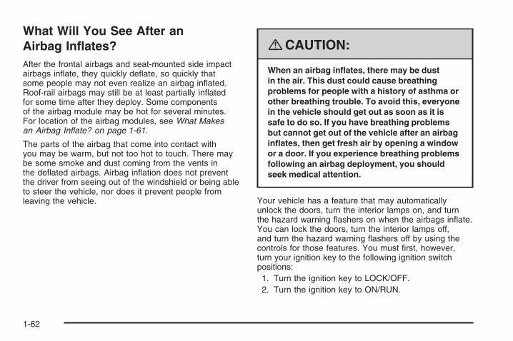
{CAUTION:
When an airbag inflates, there may be dustin the air. This dust could cause breathingproblems for people with a history of asthma orother breathing trouble. To avoid this, everyonein the vehicle should get out as soon as it issafe to do so. If you have breathing problemsbut cannot get out of the vehicle after an airbaginflates, then get fresh air by opening a windowor a door. If you experience breathing problemsfollowing an airbag deployment, you shouldseek medical attention.
Your vehicle has a feature that may automaticallyunlock the doors, turn the interior lamps on, and turnthe hazard warning flashers on when the airbags inflate.You can lock the doors, turn the interior lamps off,and turn the hazard warning flashers off by using thecontrols for those features. You must first, however,turn your ignition key to the following ignition switchpositions:1. Turn the ignition key to LOCK/OFF.2. Turn the ignition key to ON/RUN.
1-62

In many crashes severe enough to inflate the airbag,windshields are broken by vehicle deformation.Additional windshield breakage may also occur fromthe right front passenger airbag.
• Airbags are designed to inflate only once. After anairbag inflates, you will need some new parts forthe airbag system. If you do not get them, the airbagsystem will not be there to help protect you inanother crash. A new system will include airbagmodules and possibly other parts. The servicemanual for your vehicle covers the need to replaceother parts.
• Your vehicle has a crash sensing and diagnosticmodule which records information after a crash.See Vehicle Data Recording and Privacy onpage 7-15 and Event Data Recorders on page 7-15.
• Let only qualified technicians work on the airbagsystems. Improper service can mean that anairbag system will not work properly. See yourdealer/retailer for service.
Passenger Sensing SystemIf your vehicle has a right front passenger seat,your vehicle has a passenger sensing system forthe right front passenger position. The passengerairbag status indicator will be visible on the instrumentpanel when you start your vehicle.
The words ON and OFF, or the symbol for on and off,will be visible during the system check. When thesystem check is complete, either the word ON or theword OFF, or the symbol for on or off, will be visible.See Passenger Airbag Status Indicator on page 3-30.
The passenger sensing system will turn off the rightfront passenger frontal airbag under certain conditions.The driver airbags are not part of the passengersensing system.
United States Canada
1-63

The passenger sensing system works with sensors thatare part of the right front passenger seat and safetybelt. The sensors are designed to detect the presenceof a properly-seated occupant and determine if theright front passenger frontal airbag should be enabled(may inflate) or not.
Accident statistics show that children are safer if theyare restrained in the rear rather than the front seat.
We recommend that children be secured in a rear seat,including: an infant or a child riding in a rear-facingchild restraint; a child riding in a forward-facing childseat; an older child riding in a booster seat; and children,who are large enough, using safety belts.
A label on your sun visor says, “Never put a rear-facingchild seat in the front.” This is because the risk to therear-facing child is so great, if the airbag deploys.
{CAUTION:
A child in a rear-facing child restraint can beseriously injured or killed if the right frontpassenger’s airbag inflates. This is becausethe back of the rear-facing child restraintwould be very close to the inflating airbag.
Even if the passenger sensing system hasturned off the right front passenger’s frontalairbag, no system is fail-safe. No one canguarantee that an airbag will not deploy undersome unusual circumstance, even thoughit is turned off. Rear-facing child restraintsshould be secured in a rear seat, even if theairbag is off.
If you secure a forward-facing child restraintin the right front seat, always move the frontpassenger seat as far back as it will go.It is better to secure the child restraint in arear seat.
1-64

If your vehicle does not have a rear seat that willaccommodate a rear-facing child restraint, werecommend that rear-facing child restraints not betransported in your vehicle, even if the airbag is off.
The passenger sensing system is designed to turn offthe right front passenger frontal airbag if:
• The right front passenger seat is unoccupied.
• The system determines that an infant is present ina rear-facing infant seat.
• The system determines that a small child is presentin a child restraint.
• The system determines that a small child is presentin a booster seat.
• A right front passenger takes his/her weight off ofthe seat for a period of time.
• The right front passenger seat is occupied by asmaller person, such as a child who has outgrownchild restraints.
• Or, if there is a critical problem with the airbagsystem or the passenger sensing system.
When the passenger sensing system has turned off theright front passenger frontal airbag, the off indicatorwill light and stay lit to remind you that the airbag is off.See Passenger Airbag Status Indicator on page 3-30.
If a child restraint has been installed and the onindicator is lit, turn the vehicle off. Remove the childrestraint from the vehicle and reinstall the child restraintfollowing the child restraint manufacturer’s directionsand refer to Securing a Child Restraint in the Right FrontSeat Position on page 1-49.
If, after reinstalling the child restraint and restarting thevehicle, the on indicator is still lit, check to make sure thatthe vehicle’s seatback is not pressing the child restraintinto the seat cushion. If this happens, slightly reclinethe vehicle’s seatback and adjust the seat cushion ifpossible. Also make sure the child restraint is not trappedunder the vehicle head restraint. If this happens, adjustthe head restraint. See Head Restraints on page 1-2.
Remove any additional material from the seat suchas blankets, cushions, seat covers, seat heaters,or seat massagers before reinstalling or securingthe child restraint.
If the on indicator is still lit, secure the child in thechild restraint in a rear seat position in the vehicle,and check with your dealer/retailer. If no rear seat isavailable, do not install a child restraint in this vehicle,and check with your dealer/retailer.
The passenger sensing system is designed to enable(may inflate) the right front passenger frontal airbaganytime the system senses that a person of adult sizeis sitting properly in the right front passenger seat.
1-65

When the passenger sensing system has allowed theairbag to be enabled, the on indicator will light and staylit to remind you that the airbag is active.
For some children who have outgrown child restraintsand for very small adults, the passenger sensing systemmay or may not turn off the right front passengerfrontal airbag, depending upon the person’s seatingposture and body build. Everyone in your vehicle whohas outgrown child restraints should wear a safetybelt properly — whether or not there is an airbag forthat person.
If a person of adult-size is sitting in the right frontpassenger seat, but the off indicator is lit, it could bebecause that person is not sitting properly in the seat.If this happens, turn the vehicle off, remove anyadditional material from the seat, such as blankets,cushions, seat covers, seat heaters or seat massagersand ask the person to place the seatback in the fullyupright position, then sit upright in the seat, centered onthe seat cushion, with the person’s legs comfortablyextended. Restart the vehicle and have the personremain in this position for two to three minutes.This will allow the system to detect that person andthen enable the right front passenger frontal airbag.
Safety belts help keep the passenger in position onthe seat during vehicle maneuvers and braking, whichhelps the passenger sensing system maintain thepassenger airbag status. See “Safety Belts” and“Child Restraints” in the Index for additional informationabout the importance of proper restraint use.
1-66

If you ever pull the shoulder portion of the belt out allthe way, you will engage the child restraint lockingfeature. This may unintentionally cause the passengersensing system to turn the airbag(s) off for someadult size occupants. If this happens, just let the beltgo back all the way and start again.
{CAUTION:
If the airbag readiness light in the instrumentpanel cluster ever comes on and stays on,it means that something may be wrong withthe airbag system. If this ever happens, havethe vehicle serviced promptly, because anadult-size person sitting in the right frontpassenger’s seat may not have the protectionof the airbag(s). See Airbag Readiness Lighton page 3-29 for more on this, includingimportant safety information.
A thick layer of additional material, such as a blanketor cushion, or aftermarket equipment such as seatcovers, seat heaters, and seat massagers can affecthow well the passenger sensing system operates.We recommend that you not use seat covers orother aftermarket equipment other than any that GMhas approved for your specific vehicle. See AddingEquipment to Your Airbag-Equipped Vehicle onpage 1-68 for more information about modificationsthat can affect how the system operates.
{CAUTION:
Stowing of articles under the passenger’sseat or between the passenger’s seat cushionand seatback may interfere with the properoperation of the passenger sensing system.
1-67

Servicing Your Airbag-EquippedVehicleAirbags affect how your vehicle should be serviced.There are parts of the airbag system in several placesaround your vehicle. Your dealer/retailer and theservice manual have information about servicing yourvehicle and the airbag system. To purchase a servicemanual, see Service Publications Ordering Informationon page 7-14.
{CAUTION:
For up to 10 seconds after the ignition isturned off and the battery is disconnected,an airbag can still inflate during improperservice. You can be injured if you are closeto an airbag when it inflates. Avoid yellowconnectors. They are probably part of theairbag system. Be sure to follow properservice procedures, and make sure the personperforming work for you is qualified to do so.
Adding Equipment to YourAirbag-Equipped Vehicle
Q: Is there anything I might add to or changeabout the vehicle that could keep the airbagsfrom working properly?
A: Yes. If you add things that change your vehicle’sframe, bumper system, height, front end or sidesheet metal, they may keep the airbag system fromworking properly. Changing or moving any partsof the front seats, safety belts, the airbag sensingand diagnostic module, steering wheel, instrumentpanel, roof-rail airbag modules, ceiling headlineror pillar garnish trim, front sensors, side impactsensors, rollover sensor module, or airbag wiringcan affect the operation of the airbag system.
1-68

In addition, your vehicle has a passenger sensingsystem for the right front passenger’s position,which includes sensors that are part of thepassenger’s seat. The passenger sensing systemmay not operate properly if the original seattrim is replaced with non-GM covers, upholsteryor trim, or with GM covers, upholstery or trimdesigned for a different vehicle. Any object,such as an aftermarket seat heater or a comfortenhancing pad or device, installed under or ontop of the seat fabric, could also interfere withthe operation of the passenger sensing system.This could either prevent proper deployment ofthe passenger airbag(s) or prevent the passengersensing system from properly turning off thepassenger airbag(s). See Passenger SensingSystem on page 1-63.
If you have any questions about this, you shouldcontact Customer Assistance before you modifyyour vehicle. The phone numbers and addressesfor Customer Assistance are in Step Two ofthe Customer Satisfaction Procedure in this manual.See Customer Satisfaction Procedure on page 7-2.
If your vehicle has rollover roof-rail airbags, seeDifferent Size Tires and Wheels on page 5-62for additional important information.
Q: Because I have a disability, I have to get myvehicle modified. How can I find out whetherthis will affect my airbag system?
A: If you have questions, call Customer Assistance.The phone numbers and addresses for CustomerAssistance are in Step Two of the CustomerSatisfaction Procedure in this manual. SeeCustomer Satisfaction Procedure on page 7-2.
In addition, your dealer/retailer and the service manualhave information about the location of the airbagsensors, sensing and diagnostic module and airbagwiring.
1-69
Restraint System Check
Checking the Restraint Systems
Safety BeltsNow and then, make sure the safety belt reminderlight and all your belts, buckles, latch plates,retractors and anchorages are working properly.
Look for any other loose or damaged safety beltsystem parts. If you see anything that might keep asafety belt system from doing its job, have it repaired.Torn or frayed safety belts may not protect you ina crash. They can rip apart under impact forces.If a belt is torn or frayed, get a new one right away.
Make sure the safety belt reminder light is working.See Safety Belt Reminders on page 3-28 for moreinformation.
Keep safety belts clean and dry. See Care of SafetyBelts on page 5-81.
AirbagsThe airbag system does not need regularly scheduledmaintenance or replacement. Make sure the airbagreadiness light is working. See Airbag Readiness Lighton page 3-29 for more information.
Notice: If an airbag covering is damaged, opened,or broken, the airbag may not work properly.Do not open or break the airbag coverings.If there are any opened or broken airbag covers,have the airbag covering and/or airbag modulereplaced. For the location of the airbag modules,see What Makes an Airbag Inflate? on page 1-61.See your dealer/retailer for service.
1-70

Replacing Restraint System PartsAfter a Crash
{CAUTION:
A crash can damage the restraint systemsin your vehicle. A damaged restraint systemmay not properly protect the person using it,resulting in serious injury or even death ina crash. To help make sure your restraintsystems are working properly after a crash,have them inspected and any necessaryreplacements made as soon as possible.
If you have had a crash, do you need new belts orLATCH system (if equipped) parts?
After a very minor crash, nothing may be necessary.But the belt assemblies that were used during anycrash may have been stressed or damaged. See yourdealer/retailer to have your safety belt assembliesinspected or replaced.
If your vehicle has the LATCH system and it wasbeing used during a crash, you may need new LATCHsystem parts.
New parts and repairs may be necessary even if thebelt or LATCH system (if equipped), was not beingused at the time of the crash.
If an airbag inflates, you will need to replace airbagsystem parts. See the part on the airbag system earlierin this section.
Have your safety belt pretensioners checked if yourvehicle has been in a crash, if your airbag readinesslight stays on after you start your vehicle, or while youare driving. See Airbag Readiness Light on page 3-29.
If you have been in a collision in which either sideof your vehicle has been hit, the vehicle’s sensingsystem may alert the automatic battery disconnect toopen. The battery will disconnect. The electricalpower to the vehicle will be off and the vehicle will notstart. The airbag readiness light will come on. SeeAirbag Readiness Light on page 3-29. To operate yourvehicle, the automatic battery disconnect must bereconnected by a qualified service technician andsensing system parts will need to be replaced.Have your vehicle serviced right away.
1-71

✍ NOTES
1-72

Keys ...............................................................2-3Remote Keyless Entry (RKE) System ................2-4Remote Keyless Entry (RKE) System
Operation ...................................................2-5
Doors and Locks .............................................2-7Door Locks ....................................................2-7Power Door Locks ..........................................2-7Delayed Locking .............................................2-7Rear Door Security Locks ................................2-8Lockout Protection ..........................................2-8Liftgate .........................................................2-9
Windows ........................................................2-10Power Windows ............................................2-11Sun Visors ...................................................2-12
Theft-Deterrent Systems ..................................2-13Content Theft-Deterrent .................................2-13PASS-Key® III+ Electronic Immobilizer .............2-14PASS-Key® III+ Electronic Immobilizer
Operation .................................................2-15
Starting and Operating Your Vehicle ................2-16New Vehicle Break-In ....................................2-16Ignition Positions ..........................................2-17Retained Accessory Power (RAP) ...................2-18Starting the Engine (Automatic Engine
Start/Stop) ................................................2-18Engine Coolant Heater ..................................2-22Automatic Transmission Operation ...................2-23Parking Brake ..............................................2-26Regenerative Braking ....................................2-26Shifting Into PARK (P) ...................................2-27Shifting Out of PARK (P) ...............................2-28Parking Over Things That Burn .......................2-29Engine Exhaust ............................................2-29Running the Vehicle While Parked ..................2-30
Mirrors ...........................................................2-31Manual Rearview Mirror .................................2-31Automatic Dimming Rearview Mirror ................2-31Outside Power Mirrors ...................................2-32Outside Convex Mirror ...................................2-32Outside Heated Mirrors ..................................2-32
Section 2 Features and Controls
2-1

OnStar® System .............................................2-33Universal Home Remote System ......................2-36
Universal Home Remote System Operation(With One Triangular LED) ...........................2-37
Storage Areas ................................................2-41Glove Box ...................................................2-41Cupholders ..................................................2-42Instrument Panel Storage ...............................2-42
Sunglasses Storage Compartment ...................2-42Center Console Storage .................................2-42Rear Seat Armrest ........................................2-43Convenience Net ..........................................2-43Cargo Cover ................................................2-43Cargo Tie Downs ..........................................2-43Cargo Management System ...........................2-44
Sunroof .........................................................2-44
Section 2 Features and Controls
2-2

Keys
{CAUTION:
Leaving children in a vehicle with the ignitionkey is dangerous for many reasons, childrenor others could be badly injured or even killed.They could operate the power windows orother controls or even make the vehicle move.The windows will function with the keys in theignition and they could be seriously injuredor killed if caught in the path of a closingwindow. Do not leave the keys in a vehiclewith children.
The two keys can be used for the ignition and all locks.
The key code is stamped on the key number plate andcan be used to make new keys at any dealer/retailer.Store this information in a safe place outside your vehicle.
Notice: If you ever lock your keys in your vehicle,you may have to damage the vehicle to get in.Be sure you have spare keys.
If you are locked out of your vehicle, contact RoadsideAssistance. See Roadside Assistance Program onpage 7-6 for more information.
2-3

Remote Keyless Entry (RKE)SystemIf this vehicle has the Remote Keyless Entry (RKE)system, it operates on a radio frequency subjectto Federal Communications Commission (FCC)Rules and with Industry Canada.
This device complies with Part 15 of the FCC Rules.Operation is subject to the following two conditions:
1. This device may not cause interference.
2. This device must accept any interference received,including interference that may cause undesiredoperation of the device.
This device complies with RSS-210 of Industry Canada.Operation is subject to the following two conditions:
1. This device may not cause interference.
2. This device must accept any interference received,including interference that may cause undesiredoperation of the device.
Changes or modifications to this system by other thanan authorized service facility could void authorization touse this equipment.
If there is a decrease in the RKE operating range,try this:
• Check the distance. The transmitter may be toofar from the vehicle. Stand closer during rainyor snowy weather.
• Check the location. Other vehicles or objects maybe blocking the signal. Take a few steps to theleft or right, hold the transmitter higher, andtry again.
• Check the transmitter’s battery. See “BatteryReplacement” later in this section.
• If the transmitter is still not working correctly,see your dealer/retailer or a qualified technicianfor service.
2-4

Remote Keyless Entry (RKE)System OperationThe vehicle’s doors can be locked and unlocked fromabout 3 feet (1 m) up to 65 feet (20 m) away withthe Remote Keyless Entry (RKE) transmitter.
There are other conditions which can affect theperformance of the transmitter. See Remote KeylessEntry (RKE) System on page 2-4.
Q (Lock): Press Q to lock all the doors, includingthe liftgate.
" (Unlock): Press " to unlock the driver’s door. If " ispressed again within five seconds, all other doors willunlock. The interior lamps will come on for 20 secondsor until the ignition is turned on.
L (Vehicle Locator/Panic Alarm): Press andrelease L to activate the alarm. The turn signal lampswill flash and the horn will sound three times.
Press and hold L for more than two seconds and theturn signal lamps will flash and the horn will soundfor 30 seconds.
To turn the alarm off, press L again or turn theignition to ON/RUN.
2-5

Matching Transmitter(s) to YourVehicleEach RKE transmitter is coded to prevent anothertransmitter from unlocking your vehicle. If a transmitter islost or stolen, a replacement can be purchased throughyour dealer/retailer. All transmitters need to be re-codedto match the new transmitters. The lost transmitter willno longer work after the new transmitters are re-coded.Up to eight transmitters can be matched.
To match a new transmitter, see “HOLD STEM TORELEARN REMOTE KEY” under DIC Operation andDisplays on page 3-44.
Battery ReplacementReplace the battery if the REPLACE BATTERY INREMOTE KEY message displays on the DriverInformation Center (DIC).
Notice: When replacing the battery, use care not totouch any of the circuitry. Static from your bodytransferred to these surfaces may damage thetransmitter.
To replace the battery:
1. Separate the halves of the transmitter with a flatthin object inserted into the notch on the side.
2. Remove the old battery. Do not use a metal object.
3. Insert the new battery, positive side facing down.Replace with a CR2032 or equivalent battery.
4. Put the transmitter back together tightly.
2-6

Doors and Locks
Door Locks
{CAUTION:
Unlocked doors can be dangerous.• Passengers, especially children, can easily
open the doors and fall out of a movingvehicle. When a door is locked, the handlewill not open it. You increase the chance ofbeing thrown out of the vehicle in a crash ifthe doors are not locked. So, wear safetybelts properly and lock the doors wheneveryou drive.
• Young children who get into unlockedvehicles may be unable to get out. A childcan be overcome by extreme heat and cansuffer permanent injuries or even deathfrom heat stroke. Always lock your vehiclewhenever you leave it.
• Outsiders can easily enter through anunlocked door when you slow down or stopyour vehicle. Locking your doors can helpprevent this from happening.
To lock or unlock the driver’s door, use the key from theoutside or the door lock from the inside.
Power Door Locks
T: The power door lock switches are located on thedriver’s door.
• To unlock the doors, press the right side of theswitch.
• Remove the ignition key and press the left side ofthe switch to lock all of the doors.
Delayed LockingA chime will sound to indicate a door or liftgate is openwhen you try to lock the doors with the power door lockswitch. The doors will not lock, and the theft-deterrentsystem will not arm until all the doors are closed andfive seconds have passed.
2-7

Rear Door Security LocksYour vehicle has rear door security locks to preventpassengers from opening the rear doors from the inside.
Open the rear doors toaccess the security lockson the inside edge ofeach door.
To set the locks, insert a key into the slot and turn it tothe horizontal position. The door can only be opened fromthe outside with the door unlocked. To return the door tonormal operation, turn the slot to the vertical position.
Lockout ProtectionWhen you press the power door lock switch with thekey in the ignition, and any door is open, all the doorslock and the driver’s door unlocks. When doors areclosed with the key in the ignition, the horn will soundas a reminder.
If you lock the doors with the remote Keyless Entry(RKE) transmitter, and the key is in the ignition, a chimesounds and all except the driver’s door lock.
The lockout protection feature can be overridden byholding the power door lock switch for three seconds.
2-8

Liftgate
{CAUTION:
It can be dangerous to drive with the liftgate orliftglass open because carbon monoxide (CO)gas can come into your vehicle. You cannot seeor smell CO. It can cause unconsciousness andeven death. If you must drive with the liftgateopen or if electrical wiring or other cableconnections must pass through the sealbetween the body and the liftgate or liftglass:
• Make sure all other windows are shut.• Turn the fan on your climate control system
to its highest speed and select the controlsetting that will force outside air into yourvehicle. See “Climate Control System” inthe Index.
• If you have air outlets on or under theinstrument panel, open them all the way.See Engine Exhaust on page 2-29.
To lock or unlock the liftgate, press the button on theRemote Keyless Entry (RKE) transmitter twice orthe power door lock switch.
To open the liftgate, press the touchpad on theunderside of the liftgate handle and pull up.
To close the liftgate, pull down using the handle andclose until it latches.
Liftgate Operation with Loss of Power
To open the liftgate ifthe vehicle’s battery isdisconnected or the voltageis low, access the releaselever.
Remove the interior trim cover on the inside of theliftgate. Use a tool to push the lever on the latch untilthe liftgate releases.
2-9

Windows
{CAUTION:
Leaving children, helpless adults, or pets in avehicle with the windows closed is dangerous.They can be overcome by the extreme heatand suffer permanent injuries or even deathfrom heat stroke. Never leave a child, ahelpless adult, or a pet alone in a vehicle,especially with the windows closed in warmor hot weather.
2-10
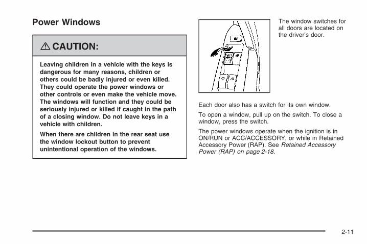
Power Windows
{CAUTION:
Leaving children in a vehicle with the keys isdangerous for many reasons, children orothers could be badly injured or even killed.They could operate the power windows orother controls or even make the vehicle move.The windows will function and they could beseriously injured or killed if caught in the pathof a closing window. Do not leave keys in avehicle with children.
When there are children in the rear seat usethe window lockout button to preventunintentional operation of the windows.
The window switches forall doors are located onthe driver’s door.
Each door also has a switch for its own window.
To open a window, pull up on the switch. To close awindow, press the switch.
The power windows operate when the ignition is inON/RUN or ACC/ACCESSORY, or while in RetainedAccessory Power (RAP). See Retained AccessoryPower (RAP) on page 2-18.
2-11

Express-Down WindowThe driver’s window switch has an express-downfeature that allows the window to be lowered withoutholding the switch. Press the switch part way, andthe driver’s window will open a small amount. Press theswitch down all the way and release it and the windowwill go down automatically.
To stop the window while it is lowering, press andrelease the switch.
Window Lockout
o (Window Lockout): Your vehicle has a lockoutfeature to prevent rear seat passengers from operatingthe windows. Press the lockout button, located with thepower window switches, to turn the feature on and off.
Sun VisorsTo block out glare, swing the sun visor down. Youcan also detach the driver’s sun visor from the centermount and slide it along the rod from side-to-sidefor greater coverage.
Visor Vanity MirrorsOn vehicles with covered visor vanity mirrors, pull downthe sun visor to access the vanity mirror.
Lighted Visor Vanity MirrorsOn vehicles with lighted visor vanity mirrors, pull downthe sun visor to access the vanity mirror. The lightswill come on when you lift the cover.
2-12

Theft-Deterrent SystemsVehicle theft is big business, especially in some cities.This vehicle has theft-deterrent features, however,they do not make it impossible to steal.
Content Theft-DeterrentYour vehicle may have a content theft-deterrent alarmsystem.
The security light islocated near the center ofthe instrument panel.
To arm the theft-deterrent system, close all doors andpress the lock button on the RKE transmitter. Thesecurity light will come on solid for approximately
30 seconds and then flashes slowly. If the lock buttonon the RKE transmitter is pressed a second time,the theft-deterrent system will activate immediately,bypassing the 30 second delay. The content theftdeterrent alarm is not armed until the security lightflashes slowly.
If any door or the liftgate are opened without using thekey or pressing the unlock button on the RKE transmitter,the exterior lamps flash and the horn will sound for about30 seconds. If the lock or unlock button on the RKEtransmitter is not pressed, the alarm sounds andperiodically repeats. If the system does not operate asdescribed above, see your dealer/retailer for service.
The theft-deterrent system also activates if you lock thedoors with a key.
To avoid setting off the alarm by accident, alwaysunlock a door with the RKE transmitter or a key.Unlocking a door any other way will set off the alarmif the system has been armed.
If you set off the alarm by accident, turn off the alarm bypressing lock or unlock on the RKE transmitter or byplacing the key in the ignition and turning it to START.
United States shown,Canada similar
2-13

Testing the AlarmTo test the alarm:
1. From inside the vehicle, lower the driver’s windowand open the driver’s door.
2. Get out of the vehicle, close the door and activatethe system by locking the doors with the RKEtransmitter.
3. Wait for the security light to flash slowly.
4. Then reach in through the window, unlock the doorwith the manual door lock and open the door.This should set off the alarm.
If the alarm does not sound when it should, but thevehicle’s headlamps flash, check to see if the hornworks. The horn fuse may be blown. To replace thefuse, see Fuses and Circuit Breakers on page 5-90.
If the alarm does not sound or the vehicle’s headlampsdo not flash, see your dealer/retailer for service.
PASS-Key® III+ ElectronicImmobilizerThe PASS-Key® III+ system operates on a radiofrequency subject to Federal CommunicationsCommission (FCC) Rules and with Industry Canada.
This device complies with Part 15 of the FCC Rules.Operation is subject to the following two conditions:
1. This device may not cause harmful interference.
2. This device must accept any interference received,including interference that may cause undesiredoperation.
This device complies with RSS-210 of Industry Canada.Operation is subject to the following two conditions:
1. This device may not cause interference.
2. This device must accept any interference received,including interference that may cause undesiredoperation of the device.
Changes or modifications to this system by other thanan authorized service facility could void authorization touse this equipment.
PASS-Key® III+ uses a radio frequency transponder inthe key that matches a decoder in the vehicle.
2-14

PASS-Key® III+ ElectronicImmobilizer OperationYour vehicle has PASS-Key® III+ (PersonalizedAutomotive Security System) theft-deterrent system.PASS-Key® III+ is a passive theft-deterrent system.
The system is automatically armed when the keyis removed from the ignition.
You do not have to manually arm or disarm the system.
The security light will come on if there is a problemwith arming or disarming the theft-deterrent system.
When the PASS-Key® III+ system senses that someoneis using the wrong key, it prevents the vehicle fromstarting. Anyone using a trial-and-error method to startthe vehicle will be discouraged because of the highnumber of electrical key codes.
When trying to start the vehicle if the engine does notstart and the security light on the instrument panelcluster comes on, there may be a problem with yourtheft-deterrent system. Turn the ignition off and try again.
If the engine still does not start, and the key appears tobe not damaged, wait about five minutes and try anotherignition key. At this time, you may also want to checkthe fuse, see Fuses and Circuit Breakers on page 5-90.If the engine still does not start with the other key, yourvehicle needs service. If your vehicle does start, the firstkey may be faulty. See your dealer/retailer who canservice the PASS-Key® III+ to have a new key made.In an emergency, contact Roadside Assistance.See Roadside Assistance Program on page 7-6.
It is possible for the PASS-Key® III+ decoder to “learn”the transponder value of a new or replacement key.Up to 10 keys may be programmed for the vehicle.The following procedure is for programming additionalkeys only. If all the currently programmed keys arelost or do not operate, you must see your dealer/retaileror a locksmith who can service PASS-Key® III+ tohave keys made and programmed to the system.
See your dealer/retailer or a locksmith who can servicePASS-Key® III+ to get a new key blank that is cutexactly as the ignition key that operates the system.
2-15

To program the new key:
1. Verify that the new key has a 1 stamped on it.
2. Insert the already programmed key in the ignitionand start the engine. If the engine will not start,see your dealer/retailer for service.
3. After the engine has started, turn the key toLOCK/OFF, and remove the key.
4. Insert the key to be programmed and turn it to theON/RUN position within five seconds of the originalkey being turned to the LOCK/OFF position.The security light will turn off once the key hasbeen programmed.
5. Repeat Steps 1 through 4 if additional keys are tobe programmed.
If you lose or damage your PASS-Key® III+ key, seeyour dealer/retailer or a locksmith who can servicePASS-Key® III+ to have a new key made.
Do not leave the key or device that disarms ordeactivates the theft deterrent system in the vehicle.
Starting and Operating YourVehicle
New Vehicle Break-InNotice: Your vehicle does not need an elaboratebreak-in. But it will perform better in the long run ifyou follow these guidelines:
• Do not drive at any one constant speed, fast orslow, for the first 500 miles (805 km). Do notmake full-throttle starts. Avoid downshifting tobrake or slow the vehicle.
• Avoid making hard stops for the first 200 miles(322 km) or so. During this time the new brakelinings are not yet broken in. Hard stopswith new linings can mean premature wear andearlier replacement. Follow this breaking-inguideline every time you get new brake linings.
• Do not tow a trailer during break-in. See Towinga Trailer on page 4-31 for the trailer towingcapabilities of your vehicle and moreinformation.
Following break-in, engine speed and load can begradually increased.
2-16

Ignition PositionsThe ignition switch can beturned to four differentpositions with the key.
To shift out of PARK (P), the ignition must be inON/RUN and the brake pedal must be pressed.
Notice: Using a tool to force the key from theignition switch could cause damage or break thekey. Use the correct key and turn the key only withyour hand. Make sure the key is in all the way. Ifnone of this works, then your vehicle needs service.
LOCK/OFF: This position locks the steering wheel,ignition, shift lever and transmission. This is theonly position in which you can insert or remove the key.If the steering wheel is locked, move it from right toleft and turn the key to ACC/ACCESSORY. If noneof this works, then your vehicle needs service.
ACC (ACC/ACCESSORY): This position operatessome of the electrical accessories, such as the radio,but not the climate control system.
Use ACC/ACCESSORY if you must have your vehiclein motion while the engine is off, for example, if yourvehicle is being pushed or towed.
ON/RUN: This is the position the switch returns afteryou start the engine and release the key. The switchstays in ON/RUN when the engine is running. But evenwhen the engine is not running, you can use ON/RUNto operate the electrical accessories, and to displaysome instrument panel warning lights.
The battery could be drained if you leave the key in theACC/ACCESSORY or ON/RUN position with the engineoff. You may not be able to start your vehicle if the batteryis allowed to drain for an extended period of time.
START: This position starts the engine. When theengine starts, release the key. The switch returns toON/RUN for normal driving. Do not turn the key toSTART if the engine is running.
Even if the engine is not running, ACC/ACCESSORYand ON/RUN allow you to operate electrical accessories,such as the radio.
2-17

Key In the IgnitionNever leave your vehicle with the keys inside, as it is aneasy target for joy riders or thieves. If you leave the key inthe ignition and park your vehicle, a chime will sound,when you open the driver’s door. Always remember toremove your key from the ignition and take it with you.This will lock your ignition and transmission. Also, alwaysremember to lock the doors.
The battery could be drained if you leave the key in theignition while your vehicle is parked. You may not beable to start your vehicle after it has been parked for anextended period of time.
Retained Accessory Power (RAP)These vehicle accessories may be used for up to10 minutes after the ignition key is turned off:
• Outside Mirror
• Power Windows
• Radio
All these features work when the ignition key is in theON/RUN or ACC/ACCESSORY positions, until a door isopened.
Starting the Engine (AutomaticEngine Start/Stop)Place the transmission in the proper gear.
Move your shift lever to PARK (P) or NEUTRAL (N).Your engine will not start in any other position -- thisis a safety feature. To restart when you are alreadymoving, use NEUTRAL (N) only.
Notice: Do not try to shift to PARK (P) if yourvehicle is moving. If you do, you could damage thetransmission. Shift to PARK (P) only when yourvehicle is stopped.
2-18

Starting Procedure1. With your foot off the accelerator pedal, turn the
ignition key to START. When the engine starts,let go of the key. The idle speed will go down asyour engine gets warm. Do not race the engineimmediately after starting it. Operate the engineand transmission gently to allow the oil to warmup and lubricate all moving parts.Your vehicle has a Computer-Controlled CrankingSystem. This feature assists in starting the engineand protects components. If the ignition key is turnedto the START position, and then released when theengine begins cranking, the engine will continuecranking for a few seconds or until the vehicle starts.If the engine does not start and the key is held inSTART for many seconds, cranking stops after15 seconds to prevent cranking motor damage.To prevent gear damage, this system also preventscranking if the engine is already running. Enginecranking can be stopped by turning the ignitionswitch to the ACC/ACCESSORY or LOCK/OFFposition.
Notice: Cranking the engine for long periods oftime, by returning the key to the START positionimmediately after cranking has ended, can overheatand damage the cranking motor, and drain thebattery. Wait at least 15 seconds between eachtry, to let the cranking motor cool down.
2. If the engine does not start after 5-10 seconds,especially in very cold weather (below 0°F or −18°C),it could be flooded with too much gasoline. Trypushing the accelerator pedal all the way to the floorand holding it there as you hold the key in STARTfor up to a maximum of 15 seconds. Wait at least15 seconds between each try, to allow the crankingmotor to cool down. When the engine starts, let go ofthe key and accelerator. If the vehicle starts brieflybut then stops again, repeat the procedure. Thisclears the extra gasoline from the engine. Do notrace the engine immediately after starting it. Operatethe engine and transmission gently until the oilwarms up and lubricates all moving parts.
Notice: Your engine is designed to work with theelectronics in your vehicle. If you add electricalparts or accessories, you could change the way theengine operates. Before adding electrical equipment,check with your dealer/retailer. If you do not, yourengine might not perform properly. Any resultingdamage would not be covered by your vehicle’swarranty.
2-19

Automatic Engine Start/Stop
{CAUTION:
There is something about your vehicle that canmake it move suddenly, and you or others canbe seriously injured. This can happen if thevehicle is in the Auto Stop mode, and the shiftlever is in DRIVE (D). Because your vehicle hasthe Automatic Engine Start/Stop feature, yourvehicle’s engine might seem to be shut offwhen you come to a complete stop. However,if you then start to exit the vehicle, as soon asyou take your foot off the brake pedal, theengine will start again and the vehicle canmove forward. If you are going to exit yourvehicle, first shift to PARK (P) and turn theignition to LOCK/OFF. Then exit.
Your vehicle has an automatic engine start/stop featurethat is a hybrid operation. After the engine is startedand has reached operating temperature, the AUTOSTOP feature may turn the engine off when you applythe brakes and come to a complete stop. When you takeyour foot off the brake pedal or press the acceleratorpedal, the engine will start. The engine will continueto run until the next AUTO STOP.
The AUTO STOP mark on the tachometer indicatesthat the engine is in AUTO STOP mode. If the driver’sdoor is opened while in AUTO STOP mode, a chime willsound.
If you are on an incline, your vehicle may roll backwardsa short distance until the engine performs an AUTOSTART. The Hill Start Assist feature will help start thevehicle on a moderate or steep incline. To restart theengine during the AUTO STOP, release the brakepedal or press the accelerator pedal. The enginestarts immediately. The vehicle continues to rununtil the next stop.
There are several conditions that may prevent an AUTOSTOP or cause an AUTO START.
2-20

The Engine Will Remain Running When:• The engine, transmission, or hybrid battery is
not warmed up yet.
• The outside temperature is high — usually above95°F (35°C) and the climate control system isworking to cool the vehicle in A/C mode (yellow lightilluminated on A/C button) or if defrost is selected.See Automatic Climate Control System onpage 3-18 for more information.
• The shift lever is in PARK (P), REVERSE (R),NEUTRAL (N), MANUAL MODE (M).
• The hybrid battery pack charge is low.
• The 12V vehicle battery charge is low, or loadsare high.
• The hood is not fully closed.
The Engine Will Restart When:• The brake pedal is released.
• The accelerator pedal is applied.
• When shifting from DRIVE (D) to PARK (P),REVERSE (R), NEUTRAL (N), MANUAL MODE (M)the engine will restart immediately.
• If the A/C button (green light illuminated on A/C)button is selected, the duration of the AUTOSTOP will depend on the outside temperature.This economy mode improves fuel economyby limiting the effects of the air conditioning.The warmer it is outside, the shorter the time beforethe engine is restarted to provide cabin cooling.
• The climate control system is turned from Off toOn (econ or normal A/C, or floor/ defog/defrost). SeeAutomatic Climate Control System on page 3-18 formore information.
• The engine is required to run for either heater orclimate control performance. See “Air Conditioningand Engine Start/Stop” under Automatic ClimateControl System on page 3-18 for more information.
• The hybrid battery pack charge is low and requiresrecharging.
• Auto Stop time is greater than two minutes.
2-21

Engine Coolant HeaterThe engine coolant heater, if available, can help in coldweather conditions at or below 0°F (−18°C) for easierstarting and better fuel economy during engine warm-up.Plug in the coolant heater at least four hours beforestarting your vehicle. An internal thermostat in theplug-end of the cord may exist which will preventengine coolant heater operation at temperaturesabove 0° F (−18° C).
To Use the Engine Coolant Heater1. Turn off the engine.
2. Open the hood and unwrap the electrical cord. Theengine coolant heater cord is located near the aircleaner box on the passenger side of the enginecompartment. See Engine Compartment Overviewon page 5-12 for more information on location.
3. Plug the cord into a normal, grounded 110-volt ACoutlet.
{CAUTION:
Plugging the cord into an ungrounded outletcould cause an electrical shock. Also, thewrong kind of extension cord could overheatand cause a fire. You could be seriouslyinjured. Plug the cord into a properly groundedthree-prong 110-volt AC outlet. If the cord willnot reach, use a heavy-duty three-prongextension cord rated for at least 15 amps.
4. Before starting the engine, be sure to unplug andstore the cord as it was before to keep it awayfrom moving engine parts. If you do not, it couldbe damaged.
How long should you keep the coolant heater pluggedin? The answer depends on the outside temperature,the kind of oil you have, and some other things. Instead oftrying to list everything here, we ask that you contact yourdealer/retailer in the area where you will be parking yourvehicle. The dealer/retailer can give you the best advicefor that particular area.
2-22

Automatic Transmission OperationIf your vehicle has an automatic transmission, theshift lever is located on the console between the seats.
There are several differentpositions for the automatictransmission.
PARK (P): This position locks your front wheels. It isthe best position to use when you start your enginebecause your vehicle cannot move easily.
{CAUTION:
It is dangerous to get out of your vehicle if theshift lever is not fully in PARK (P) with theparking brake firmly set. Your vehicle can roll.Do not leave your vehicle when the engineis running unless you have to. If you haveleft the engine running, the vehicle can movesuddenly. You or others could be injured.To be sure your vehicle will not move, evenwhen you are on fairly level ground, alwaysset your parking brake and move the shiftlever to PARK (P). See Shifting Into PARK (P)on page 2-27. If you are pulling a trailer,see Towing a Trailer on page 4-31.
Make sure the shift lever is fully in PARK (P) beforestarting the engine. Your vehicle has an automatictransmission shift lock control system. You have to fullyapply your regular brakes first and then press the shiftlever button before you can shift from PARK (P) when theignition key is in RUN. If you cannot shift out of PARK (P),ease pressure on the shift lever and push the shift leverall the way into PARK (P) as you maintain brakeapplication. Then press the shift lever button and movethe shift lever into another gear. See Shifting Out ofPARK (P) on page 2-28.
2-23
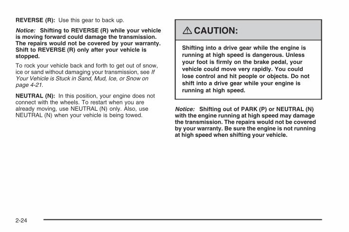
REVERSE (R): Use this gear to back up.
Notice: Shifting to REVERSE (R) while your vehicleis moving forward could damage the transmission.The repairs would not be covered by your warranty.Shift to REVERSE (R) only after your vehicle isstopped.
To rock your vehicle back and forth to get out of snow,ice or sand without damaging your transmission, see IfYour Vehicle is Stuck in Sand, Mud, Ice, or Snow onpage 4-21.
NEUTRAL (N): In this position, your engine does notconnect with the wheels. To restart when you arealready moving, use NEUTRAL (N) only. Also, useNEUTRAL (N) when your vehicle is being towed.
{CAUTION:
Shifting into a drive gear while the engine isrunning at high speed is dangerous. Unlessyour foot is firmly on the brake pedal, yourvehicle could move very rapidly. You couldlose control and hit people or objects. Do notshift into a drive gear while your engine isrunning at high speed.
Notice: Shifting out of PARK (P) or NEUTRAL (N)with the engine running at high speed may damagethe transmission. The repairs would not be coveredby your warranty. Be sure the engine is not runningat high speed when shifting your vehicle.
2-24

DRIVE (D): This position is for normal driving withthe automatic transmission. It provides the bestfuel economy for your vehicle. If you need morepower for passing, and you are:
• Going less than about 35 mph (55 km/h), push youraccelerator pedal about halfway down.
• Going about 35 mph (55 km/h), push youraccelerator all the way down.
Downshifting the transmission in slippery road conditionscould result in skidding, see “Skidding” under Loss ofControl on page 4-12.
MANUAL (M): This position allows you to change gearssimilar to a manual transmission. If your vehicle hasthis feature, see Manual Shift Mode.
Notice: Spinning the tires or holding the vehiclein one place on a hill using only the acceleratorpedal may damage the transmission. The repair willnot be covered by your warranty. If you are stuck,do not spin the tires. When stopping on a hill,use the brakes to hold the vehicle in place.
Manual Shift Mode (MSM)(Automatic Transmission)To use this feature, do the following:1. Move the shift lever from DRIVE (D) rearward to the
MANUAL MODE (M).The display will show a 3 for third gear.When coming to a stop in the manual position, thevehicle will automatically shift to FIRST (1) gear.
2. Press the plus (+) button to upshift or the minus (−)button to downshift.
While driving in MSM, the vehicle will have sportierperformance. Use this when you want the vehicle tostay in gear longer or to downshift for more poweror engine braking.
The transmission will only allow you to shift into a gearrange appropriate for the vehicle speed.
• The transmission will not automatically shift tothe next higher gear range without pressingthe button on the shifter handle.
• The transmission will not allow shifting to the nextlower gear if the vehicle speed is too high.
If the vehicle does not respond to a gear change, ordetects a problem with the transmission, the rangeof gears may be reduced and the Malfunction IndicatorLamp will come on. See Malfunction Indicator Lampon page 3-36.
2-25

Parking Brake
The parking brake lever is located to the right of thedriver’s seat.
To set the parking brake, hold the brake pedal downand pull up on the parking brake lever. If the ignition ison, the brake system warning light will come on.
To release the parking brake, hold the brake pedaldown. Pull the parking brake lever up until you can pressthe release button. Hold the release button in as youmove the brake lever all the way down.
Release the parking brake before driving the vehicle.
Notice: Driving with the parking brake on canoverheat the brake system and cause prematurewear or damage to brake system parts. Make surethat the parking brake is fully released and the brakewarning light is off before driving.
Regenerative BrakingRegenerative braking takes some of the energy from themoving vehicle and turns it back into electrical energy.This energy is then stored back into the vehicle’s hybridbattery system, contributing to increased fuel efficiency.
The system works whenever you take your foot off theaccelerator pedal while your vehicle is moving in aforward gear. This causes your vehicle to slow downslightly faster. It may feel like the brake pedal isbeing pressed, even when it is not.
2-26

Shifting Into PARK (P)
{CAUTION:
It can be dangerous to get out of your vehicleif the shift lever is not fully in PARK (P) withthe parking brake firmly set. Your vehicle canroll. If you have left the engine running, thevehicle can move suddenly. You or otherscould be injured. To be sure your vehicle willnot move, even when you are on fairly levelground, use the steps that follow. If you arepulling a trailer, see Towing a Trailer onpage 4-31.
1. Hold the brake pedal down with your foot and setthe parking brake. See Parking Brake on page 2-26for more information.
2. Move the shift lever into PARK (P) by pressing thebutton on the shift lever and pushing the lever allthe way toward the front of the vehicle.
3. Turn the ignition key to LOCK/OFF.
4. Remove the key and take it with you. If you canleave your vehicle with the key, your vehicle isin PARK (P).
Leaving Your Vehicle With the EngineRunning
{CAUTION:
It can be dangerous to leave your vehicle withthe engine running. Your vehicle could movesuddenly if the shift lever is not fully inPARK (P) with the parking brake firmly set.And, if you leave the vehicle with the enginerunning, it could overheat and even catch fire.You or others could be injured. Do not leaveyour vehicle with the engine running.
If you have to leave your vehicle with the enginerunning, be sure your vehicle is in PARK (P) and yourparking brake is firmly set before you leave it. After youhave moved the shift lever into PARK (P), hold theregular brake pedal down. Then, see if you can move theshift lever away from PARK (P) without first pressing thebutton on the console shift lever. If you can, it means thatthe shift lever was not fully locked into PARK (P).
2-27

Torque LockIf you are parking on a hill and you do not shift yourtransmission into PARK (P) properly, the weight of thevehicle may put too much force on the parking pawlin the transmission. You may find it difficult to pullthe shift lever out of PARK (P). This is called “torquelock.” To prevent torque lock, set the parking brakeand then shift into PARK (P) properly before you leavethe driver’s seat. To find out how, see Shifting IntoPARK (P) on page 2-27.
When you are ready to drive, move the shift lever out ofPARK (P) before you release the parking brake.
If torque lock does occur, you may need to have anothervehicle push yours a little uphill to take some of thepressure from the parking pawl in the transmission,so you can pull the shift lever out of PARK (P).
Shifting Out of PARK (P)This vehicle has an electronic shift lock release system.The shift lock release is designed to:
• Prevent ignition key removal unless the shift leveris in PARK (P) with the shift lever button fullyreleased, and
• Prevent movement of the shift lever out ofPARK (P), unless the ignition is in ON/RUNand the regular brake pedal is applied.
The shift lock release is always functional except in thecase of an uncharged or low voltage (less than 9 volt)battery.
If your vehicle has an uncharged battery or a batterywith low voltage, try charging or jump starting thebattery. See Jump Starting on page 5-34 for moreinformation.
2-28
To shift out of PARK (P) use the following:
1. Apply the brake pedal.
2. Press the shift lever button.
3. Move the shift lever to the desired position.
If you still are unable to shift out of PARK (P):
1. Fully release the shift lever button.
2. Hold the brake pedal down and press the shift leverbutton again.
3. Move the shift lever to the desired position.
If you still cannot move the shift lever from PARK (P),consult your dealer/retailer or a professional towingservice.
Parking Over Things That Burn
{CAUTION:
Things that can burn could touch hot exhaustparts under your vehicle and ignite. Do notpark over papers, leaves, dry grass, or otherthings that can burn.
Engine Exhaust
{CAUTION:
Engine exhaust can kill. It contains the gascarbon monoxide (CO), which you cannotsee or smell. It can cause unconsciousnessand death.
You might have exhaust coming in if:• The exhaust system sounds strange or
different.• Your vehicle gets rusty underneath.• Your vehicle was damaged in a collision.• Your vehicle was damaged when driving
over high points on the road or over roaddebris.
• Repairs were not done correctly.• Your vehicle or the exhaust system has
been modified improperly.
If you ever suspect exhaust is coming intoyour vehicle:
• Drive it only with all the windows down toblow out any CO; and
• Have your vehicle fixed immediately.
2-29

Running the Vehicle While ParkedIt is better not to park with the engine running. But if youever have to, here are some things to know.
{CAUTION:
There is something about your vehicle that canmake it move suddenly, and you or others canbe seriously injured. This can happen if thevehicle is in the Auto Stop mode, and the shiftlever is in DRIVE (D). Because your vehicle hasthe Automatic Engine Start/Stop feature, yourvehicle’s engine might seem to be shut offwhen you come to a complete stop. However,if you then start to exit the vehicle, as soon asyou take your foot off the brake pedal, theengine will start again and the vehicle canmove forward. If you are going to exit yourvehicle, first shift to PARK (P) and turn theignition to LOCK/OFF. Then exit.
{CAUTION:
Idling the engine with the climate controlsystem off could allow dangerous exhaust intoyour vehicle. See the earlier caution underEngine Exhaust on page 2-29.
Also, idling in a closed-in place can let deadlycarbon monoxide (CO) into your vehicle even ifthe climate control fan is at the highest setting.One place this can happen is a garage.Exhaust — with CO — can come in easily.NEVER park in a garage with the enginerunning.
Also see “If You Are Caught in a Blizzard”under Winter Driving on page 4-17.
2-30

{CAUTION:
It can be dangerous to get out of your vehicleif the shift lever is not fully in PARK (P) withthe parking brake firmly set. Your vehicle canroll. Do not leave your vehicle when the engineis running unless you have to. If you have leftthe engine running, the vehicle can movesuddenly. You or others could be injured.To be sure your vehicle will not move, evenwhen you are on fairly level ground, alwaysset the parking brake and move the shift leverto PARK (P).
Follow the proper steps to be sure your vehicle will notmove. See Shifting Into PARK (P) on page 2-27.
If you are parking on a hill and if you are pulling a trailer,also see Towing a Trailer on page 4-31.
Mirrors
Manual Rearview MirrorIf the vehicle has the manual rearview mirror, it can beadjusted by holding the mirror in the center to moveit for a clearer view of behind your vehicle. Reduce theglare of headlamps from behind by pushing the leverforward or pulling it back for daytime/nighttime use.
Automatic Dimming Rearview MirrorIf the vehicle has the automatic dimming rearviewmirror, it can be adjusted by holding the mirror in thecenter to move it up or down and side to side.
Press and hold the button, located on the mirror,for about three seconds to turn the automatic dimmingfeature on or off. The indicator light comes on whenthis feature is active. The automatic dimming featureturns on each time the vehicle is started.
2-31

Outside Power Mirrors
The outside power mirrorcontrol is located on thedriver side door.
1. Turn the knob to the left (L) for the driver sidemirror and to the right (R) for the passengerside mirror.
2. Adjust each mirror so that you can see the side ofyour vehicle and the area behind your vehicle.
3. Turn the control to the center position so the mirrorcannot be moved.
Outside Convex Mirror
{CAUTION:
A convex mirror can make things (like othervehicles) look farther away than they really are.If you cut too sharply into the right lane, youcould hit a vehicle on your right. Check yourinside mirror or glance over your shoulderbefore changing lanes.
The passenger side mirror is convex shaped. A convexmirror’s surface is curved so more can be seen fromthe driver seat. It also makes things, like other vehicles,look farther away than they really are.
Outside Heated MirrorsYour vehicle may have this feature. When you operatethe rear window defogger, the defogger also warms theheated driver’s and passenger’s outside rearview mirrorsto help clear them of ice, snow and condensation.
2-32
OnStar® System
OnStar uses several innovative technologies and liveadvisors to provide you with a wide range of safety,security, information, and convenience services. If yourairbags deploy, the system is designed to make anautomatic call to OnStar Emergency advisors who canrequest emergency services be sent to your location.If you lock your keys in the vehicle, call OnStar at1-888-4-ONSTAR and they can send a signal to unlockyour doors. If you need roadside assistance, pressthe OnStar button and they can contact RoadsideService for you.
OnStar service is provided to you subject to the OnStarTerms and Conditions. You may cancel your OnStarservice at any time by contacting OnStar. A completeOnStar Owner’s Guide and the OnStar Terms andConditions are included in the vehicle’s OnStarSubscriber glove box literature. For more information,visit onstar.com or onstar.ca, contact OnStarat 1-888-4-ONSTAR (1-888-466-7827) or TTY1-877-248-2080, or press the OnStar button to speakwith an OnStar advisor 24 hours a day, 7 days a week.
Not all OnStar features are available on all vehicles.To check if your vehicle is equipped to provide theservices described below, or for a full description ofOnStar services and system limitations, see the OnStarOwner’s Guide in your glove box or visit onstar.com.
OnStar ServicesFor new vehicles with OnStar, the Safe & Sound Plan,or the Directions & Connections Plan is included forone year from the date of purchase. You can extendthis plan beyond the first year, or upgrade to theDirections & Connections Plan. For more information,press the OnStar button to speak with an advisor. SomeOnStar services (such as Remote Door Unlock or StolenVehicle Location Assistance) may not be available untilyou register with OnStar.
2-33

Available Services with Safe & Sound Plan• Automatic Notification of Airbag Deployment
• Advanced Automatic Crash Notification (AACN)(If equipped)
• Link to Emergency Services
• Roadside Assistance
• Stolen Vehicle Location Assistance
• AccidentAssist
• Remote Door Unlock/Vehicle Alert
• OnStar Vehicle Diagnostics
• GM Goodwrench On Demand Diagnostics
• OnStar Hands-Free Calling with30 complimentary minutes
• OnStar Virtual Advisor (U.S. Only)
Available Services included withDirections & Connections Plan• All Safe and Sound Plan Services
• Driving Directions - Advisor delivered or OnStarTurn-by-Turn Navigation (If equipped)
• RideAssist
• Information and Convenience Services
OnStar Hands-Free CallingOnStar Hands-Free Calling allows eligible OnStarsubscribers to make and receive calls using voicecommands. Hands-Free Calling is fully integratedinto the vehicle, and can be used with OnStar Pre-PaidMinute Packages. Hands-Free Calling may also be linkedto a Verizon Wireless service plan in the U.S. or a BellMobility service plan in Canada, depending on eligibility.To find out more, refer to the OnStar Owner’s Guidein the vehicle’s glove box, visit www.onstar.com orwww.onstar.ca, or speak with an OnStar advisor bypressing the OnStar button or calling 1-888-4-ONSTAR(1-888-466-7827).
OnStar Virtual AdvisorOnStar Virtual Advisor is a feature of OnStarHands-Free Calling that uses your minutes to accesslocation-based weather, local traffic reports, and stockquotes. By pressing the phone button and giving a fewsimple voice commands, you can browse through thevarious topics. See the OnStar Owner’s Guide for moreinformation (Only available in the continental U.S.).
2-34

OnStar Steering Wheel ControlsYour vehicle may have a Talk/Mute button that canbe used to interact with OnStar Hands-Free Calling.See Audio Steering Wheel Controls on page 3-76for more information.
On some vehicles, you may have to hold the buttonfor a few seconds and give the command “ONSTAR” toactivate the OnStar Hands-Free Calling. OnStar voicecommand does not work unless Personal Calling isactivated. To activate Personal Calling, see the OnStarOwner’s Guide.
On some vehicles, the mute button can be used todial numbers into voicemail systems, or to dial phoneextensions. See the OnStar Owner’s Guide formore information.
How OnStar Service WorksYour vehicle’s OnStar system has the capabilityof recording and transmitting vehicle information.This information is automatically sent to an OnStarCall Center at the time of an OnStar button press,Emergency button press or if your airbags or AACNsystem deploys. The vehicle information usually includesyour GPS location and, in the event of a crash, additionalinformation regarding the accident that your vehicle hasbeen involved in (e.g. the direction from which yourvehicle was hit). When you use the Virtual Advisor featureof OnStar Hands-Free Calling, your vehicle also sendsOnStar your GPS location so that we can provide youwith location-based services.
OnStar service cannot work unless your vehicle is in aplace where OnStar has an agreement with a wirelessservice provider for service in that area. OnStar servicealso cannot work unless you are in a place where thewireless service provider OnStar has hired for that areahas coverage, network capacity and reception when theservice is needed, and technology that is compatiblewith the OnStar service. Not all services are availableeverywhere, particularly in remote or enclosed areas,or at all times.
2-35
Location information about your vehicle is only availableif the GPS satellite signals are unobstructed andavailable.
Your vehicle must have a working electrical system(including adequate battery power) for the OnStarequipment to operate. There are other problems OnStarcannot control that may prevent OnStar from providingOnStar service to you at any particular time or place.Some examples are damage to important parts of yourvehicle in an accident, hills, tall buildings, tunnels,weather or wireless phone network congestion.
Your ResponsibilityIncrease the radio volume if you cannot hear the OnStaradvisor. If the light next to the OnStar buttons is red, thismeans that your system is not functioning properly andshould be checked by your dealer/retailer. If the lightappears clear (no light is appearing), your OnStarsubscription has expired. You can always press theOnStar button to confirm that your OnStar equipmentis active.
Universal Home RemoteSystemThe Universal Home Remote System provides a way toreplace up to three hand-held Radio-Frequency (RF)transmitters used to activate devices such as garagedoor openers, security systems, and home lighting.
This device complies with Part 15 of the FCC Rules.Operation is subject to the following two conditions:
1. This device may not cause harmful interference.
2. This device must accept any interference received,including interference that may cause undesiredoperation.
This device complies with RSS-210 of Industry Canada.Operation is subject to the following two conditions:
1. This device may not cause interference.
2. This device must accept any interference received,including interference that may cause undesiredoperation of the device.
Changes or modifications to this system by other thanan authorized service facility could void authorization touse this equipment.
2-36
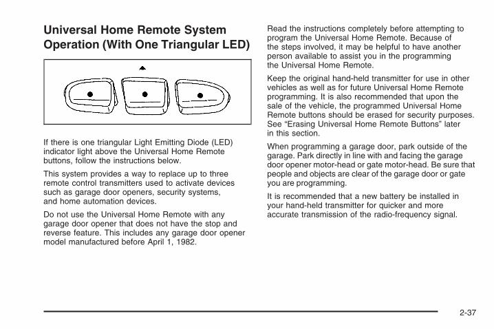
Universal Home Remote SystemOperation (With One Triangular LED)
If there is one triangular Light Emitting Diode (LED)indicator light above the Universal Home Remotebuttons, follow the instructions below.
This system provides a way to replace up to threeremote control transmitters used to activate devicessuch as garage door openers, security systems,and home automation devices.
Do not use the Universal Home Remote with anygarage door opener that does not have the stop andreverse feature. This includes any garage door openermodel manufactured before April 1, 1982.
Read the instructions completely before attempting toprogram the Universal Home Remote. Because ofthe steps involved, it may be helpful to have anotherperson available to assist you in the programmingthe Universal Home Remote.
Keep the original hand-held transmitter for use in othervehicles as well as for future Universal Home Remoteprogramming. It is also recommended that upon thesale of the vehicle, the programmed Universal HomeRemote buttons should be erased for security purposes.See “Erasing Universal Home Remote Buttons” laterin this section.
When programming a garage door, park outside of thegarage. Park directly in line with and facing the garagedoor opener motor-head or gate motor-head. Be sure thatpeople and objects are clear of the garage door or gateyou are programming.
It is recommended that a new battery be installed inyour hand-held transmitter for quicker and moreaccurate transmission of the radio-frequency signal.
2-37

Programming the Universal HomeRemote SystemIf you have questions or need help programming theUniversal Home Remote System, call 1-800-355-3515or go to www.homelink.com.
Programming a garage door opener involvestime-sensitive actions, so read the entire procedurebefore you begin. If you do not follow these actions,the device will time out and you will have to repeat theprocedure.
To program up to three devices:
1. From inside the vehicle, press and hold down thetwo outside buttons at the same time, releasing onlywhen the Universal Home Remote indicator lightbegins to flash, after 20 seconds. This step will erasethe factory settings or all previously programmedbuttons.
Do not hold down the buttons for longer than30 seconds and do not repeat this step to programthe remaining two Universal Home Remote buttons.
2. Hold the end of your hand-held transmitter about1 to 3 inches (3 to 8 cm) away from the UniversalHome Remote buttons while keeping the indicatorlight in view. The hand-held transmitter was suppliedby the manufacturer of your garage door openerreceiver (motor head unit).
3. At the same time, press and hold both the UniversalHome Remote button that you would like to useto control the garage door and the hand-heldtransmitter button. Do not release the UniversalHome Remote button or the hand-held transmitterbutton until Step 4 has been completed.Some entry gates and garage door openersmay require you to substitute Step 3 with theprocedure noted in “Gate Operator and CanadianProgramming” later in this section.
4. The indicator light on the Universal Home Remotewill flash slowly at first and then rapidly afterUniversal Home Remote successfully receives thefrequency signal from the hand-held transmitter.Release both buttons.
2-38

5. Press and hold the newly-trained Universal HomeRemote button and observe the indicator light.If the indicator light stays on continuously,the programming is complete and your garage doorshould move when the Universal Home Remotebutton is pressed and released. You do not need tocontinue the programming Steps 6 through 8 andcan stop here.If the Universal Home Remote indicator lightblinks rapidly for two seconds and then turns toa constant light, continue with the programmingSteps 6 through 8.It may be helpful to have another person availableto assist with the remaining steps.
6. After Steps 1 through 5 have been completed,locate inside the garage the garage door openerreceiver (motor-head unit). Locate the “Learn”or “Smart” button. The name and color of thebutton may vary by manufacturer.
2-39
7. Firmly press and release the “Learn” or “Smart”button. After you press this button, you will have30 seconds to complete Step 8.
8. Immediately return to the vehicle. Firmly press andhold the Universal Home Remote button, chosen inStep 3 to control the garage door, for two seconds,and then release it. If the garage door does notmove, press and hold the same button a second timefor two seconds, and then release it. Again, if thedoor does not move, press and hold the same buttona third time for two seconds, and then release.The Universal Home Remote should now activatethe garage door.
To program the remaining two Universal Home Remotebuttons, begin with Step 2 of “Programming the UniversalHome Remote System.” Do not repeat Step 1, as this willerase all previous programming from the Universal HomeRemote buttons.
Gate Operator and CanadianProgrammingIf you have questions or need help programming theUniversal Home Remote System, call 1-800-355-3515or go to www.homelink.com.
Canadian radio-frequency laws require transmittersignals to time out or quit after several seconds oftransmission. This may not be long enough for UniversalHome Remote to pick up the signal during programming.Similarly, some U.S. gate operators are manufacturedto time out in the same manner.
If you live in Canada, or you are having difficultyprogramming a gate operator or garage door openerby using the “Programming Universal Home Remote”procedures, regardless of where you live, replace Step 3under “Programming Universal Home Remote” withthe following:
Continue to press and hold the Universal Home Remotebutton while you press and release every two seconds(cycle) the hand-held transmitter button until thefrequency signal has been successfully accepted by theUniversal Home Remote. The Universal Home Remoteindicator light will flash slowly at first and then rapidly.Proceed with Step 4 under “Programming UniversalHome Remote” to complete.
2-40

Using Universal Home RemotePress and hold the appropriate Universal Home Remotebutton for at least half of a second. The indicator lightwill come on while the signal is being transmitted.
Erasing Universal Home RemoteButtonsErase the programmed buttons when you sell orterminate your lease.
To erase all programmed buttons on the UniversalHome Remote device:
1. Press and hold down the two outside buttons untilthe indicator light begins to flash, after 20 seconds.
2. Release both buttons.
Reprogramming a Single UniversalHome Remote ButtonTo reprogram any of the three Universal Home Remotebuttons, repeat the programming instructions earlierin this section, beginning with Step 2.
For help or information on the Universal Home RemoteSystem, call the customer assistance phone numberunder Customer Assistance Offices on page 7-5.
Storage Areas
Glove BoxTo open the glove box, lift up on the lever. The glovebox divider can be removed. The slots on the leftside are for storing the divider.
2-41

CupholdersThere are cupholders located in front of and behind thecenter console.
To access the cupholders behind the center console,push the button.
Instrument Panel StorageYour vehicle has a storage area located to left of thesteering wheel. Pull down on the handle to access.
Sunglasses Storage CompartmentYour vehicle may have a sunglasses storagecompartment located near the rearview mirror.Push the cover to open.
Center Console Storage
Your vehicle has a center console with an upper, lowerand rear storage area. To access the upper storagearea, lift up on the top lever. To access the lowerstorage area, lift up on the bottom lever. The top of thecenter console can extend forward. To adjust, holdthe top of the lever up and pull the top of the centerconsole forward.
2-42

Rear Seat Armrest
To access the rear seat armrest, pull the handle down.Lift the top of the armrest to access the storage area.
Convenience NetYour vehicle may have a convenience net in the rear ofthe vehicle. Store small loads as far forward as possible.The net should not be used to store heavy loads.
Cargo Cover
Your vehicle may have a cargo cover. It can be used tocover items in the rear of the vehicle. Pull the covertoward the rear of the vehicle and place each end in theslots provided. To install the cover, place each end ofthe cover in the holes behind the rear seat. To removethe cover, pull both ends toward each other.
Cargo Tie DownsThere are four cargo tie-downs located in the rearcompartment of the vehicle, that can be used tosecure small loads.
2-43

Cargo Management SystemYour vehicle may have a cargo management systemin the rear of the vehicle. The system has rails withadapters and hooks. These are used to hold the netand mesh pocket.
The adapters are used to hold the net. Slide theadapters to the desired location on the upper and lowergroove of the rail and turn the handle up to lock it inplace. Compress the rods of the net and insert them intothe corresponding openings of the adapter. The longerrod is for the upper adapter.
The hooks hold the mesh pocket. To insert a hook onthe rail, place the hook in the upper groove of therail and press it into the lower groove.
SunroofThe sunroof controlswitch is locatedbetween thesun visors.
To operate the sunroof, the ignition must be inON/RUN, ACC/ACCESSORY, or in RetainedAccessory Power (RAP). See Retained AccessoryPower (RAP) on page 2-18.Pull and release the switch quickly to express-open thesunroof. Press and release the switch quickly to stopthe sunroof before it is completely open. The sun shadeautomatically opens with the sunroof. The sunshadecannot be closed with the sunroof open.To close the sunroof, press the switch. The sunshademust be closed manually.Pull up on the switch to tilt the sunroof. Push downon the switch to close it. The sunshade must bemanually opened and closed when the sunroof isin the vent position.
2-44

Instrument Panel Overview ...............................3-4Hazard Warning Flashers ................................3-6Horn .............................................................3-6Tilt Wheel .....................................................3-6Turn Signal/Multifunction Lever .........................3-7Turn and Lane-Change Signals ........................3-7Headlamp High/Low-Beam Changer ..................3-8Flash-to-Pass .................................................3-8Windshield Wipers ..........................................3-8Rainsense™ II Wipers .....................................3-9Windshield Washer .......................................3-10Rear Window Wiper/Washer ...........................3-11Cruise Control ..............................................3-11Exterior Lamps .............................................3-14Wiper Activated Headlamps ............................3-14Daytime Running Lamps (DRL) .......................3-15Automatic Headlamp System ..........................3-15Instrument Panel Brightness ...........................3-16Dome Lamp .................................................3-16Entry Lighting ...............................................3-16Reading Lamps ............................................3-17Battery Run-Down Protection ..........................3-17Accessory Power Outlet(s) .............................3-17
Climate Controls ............................................3-18Automatic Climate Control System ...................3-18Outlet Adjustment .........................................3-23Passenger Compartment Air Filter ...................3-23
Warning Lights, Gages, and Indicators ............3-25Instrument Panel Cluster ................................3-26Speedometer and Odometer ...........................3-27Trip Odometer ..............................................3-27Tachometer .................................................3-27Safety Belt Reminders ...................................3-28Airbag Readiness Light ..................................3-29Passenger Airbag Status Indicator ...................3-30Charging System Light ..................................3-32Brake System Warning Light ..........................3-32Anti-lock Brake System (ABS) Warning Light ....3-33Traction Control System (TCS) Warning Light ...3-34Electronic Stability Program Indicator Light .......3-34Engine Coolant Temperature Warning Light ......3-35Tire Pressure Light .......................................3-35Malfunction Indicator Lamp .............................3-36Oil Pressure Light .........................................3-38Change Engine Oil Light ................................3-39Security Light ...............................................3-40Cruise Control Light ......................................3-40Highbeam On Light .......................................3-40Low Washer Fluid Warning Light .....................3-40Fuel Gage ...................................................3-41Low Fuel Warning Light .................................3-42Auto Stop Mode ...........................................3-42Charge/Assist Gage ......................................3-43Fuel Economy Light ......................................3-43
Section 3 Instrument Panel
3-1

Driver Information Center (DIC) .......................3-44DIC Operation and Displays ...........................3-44DIC Compass ..............................................3-48DIC Warnings and Messages .........................3-50
Audio System(s) .............................................3-59Setting the Clock ..........................................3-60Radio(s) ......................................................3-62
Using an MP3 ..............................................3-70XM Radio Messages .....................................3-75Audio Steering Wheel Controls .......................3-76Radio Reception ...........................................3-76Fixed Mast Antenna ......................................3-77XM™ Satellite Radio Antenna System .............3-77
Section 3 Instrument Panel
3-2

✍ NOTES
3-3

Instrument Panel Overview
3-4

The main components of the instrument panel are the following:
A. Air Outlets. See Outlet Adjustment on page 3-23.B. Instrument Panel Brightness Control. See Instrument
Panel Brightness on page 3-16.C. Turn Signal/Multifunction Lever. See Turn
Signal/Multifunction Lever on page 3-7.D. Instrument Panel Cluster. See Instrument Panel
Cluster on page 3-26.E. Windshield Wiper Lever. See Windshield Wipers on
page 3-8.F. Audio System. See Audio System(s) on page 3-59.G. Auxiliary Input Jack. See Radio(s) on page 3-62.H. Exterior Lamps Control. See Exterior Lamps
on page 3-14.I. Instrument Panel Storage Area. See Instrument
Panel Storage on page 2-42.J. Hood Release. See Hood Release on page 5-11.K. Cruise Control Buttons. See Cruise Control on
page 3-11.L. Tilt Wheel Lever. See Tilt Wheel on page 3-6.
M. Horn. See Horn on page 3-6.N. Audio Steering Wheel Controls. See Audio Steering
Wheel Controls on page 3-76.O. Rear Window Wiper/Washer. See Rear Window
Wiper/Washer on page 3-11.P. Traction Control System Button. See Traction
Control System (TCS) on page 4-7Q. Shift Lever. See Automatic Transmission Operation
on page 2-23.R. Automatic Climate Control System. See Automatic
Climate Control System on page 3-18.S. Hazard Warning Flasher Button. See Hazard
Warning Flashers on page 3-6.T. Passenger Air Bag Status Indicator. See Passenger
Airbag Status Indicator on page 3-30.U. Passenger Safety Belt Reminder Display.
See Safety Belt Reminders on page 3-28.V. Glove Box. See Glove Box on page 2-41.
3-5

Hazard Warning FlashersThe hazard warning flashers let you warn the police andothers that you have a problem. The front and rearturn signal lamps will flash on and off.
The hazard warningflasher button is on theinstrument panel.
Press the button to make the front and rear turn signallamps flash on and off. Press again to turn the flasherscompletely off.
The hazard warning flashers work even if the key is notin the ignition switch.
HornPress near or on the horn symbols on the steeringwheel pad to sound the horn.
Tilt WheelThe vehicle has a tilt steering wheel which can beadjusted before driving.
The tilt lever is on the lower left side of the steeringcolumn.
To tilt the wheel, hold the wheel and push the leverdown. Then, move the wheel to a comfortable positionand pull the lever up firmly to lock the steering columnin place.
3-6

Turn Signal/Multifunction Lever
The lever on the left side of the steering columnincludes:
• G Turn and Lane-Change Signals. See Turn andLane-Change Signals on page 3-7.
• 3 Headlamp High/Low-Beam Changer. SeeHeadlamp High/Low-Beam Changer on page 3-8.
• Flash-to-Pass Feature. See Flash-to-Pass onpage 3-8.
Turn and Lane-Change SignalsThe turn signal has one upward (for right) and onedownward (for left) positions, which allow you to signala turn or a lane change.
To signal a turn, move the lever all the way up or down.When the turn is finished, the lever returns automaticallyto the original position.
An arrow on the instrumentpanel cluster flashes in thedirection of the turn orlane change.
To signal a lane change, slightly raise or lower the leveruntil the arrow starts to flash and release the lever.The turn signal flashes automatically three times.
As you signal a turn or a lane change, if the arrowsflash rapidly, a signal bulb may be burned out and otherdrivers will not see your turn signal.
If a bulb is burned out, replace it to help avoid anaccident. If the arrows do not go on at all when yousignal a turn, check the fuse, see Fuses and CircuitBreakers on page 5-90 and for burned-out bulbs.
3-7

Headlamp High/Low-Beam ChangerTo change the headlamps from low beam to high orhigh beam to low, push the turn signal lever all the waytowards the instrument panel and release it.
This indicator light turns onin the instrument panelcluster when the highbeams are on.
Flash-to-PassThis feature lets you use your high-beam headlamps tosignal a driver in front of you that you want to pass.
To flash the high beams from low beam, pull the turnsignal/multifunction lever all the way towards you.Then release it.
Windshield WipersClear ice and snow from the wiper blades before usingthem. If the wiper blades are frozen to the windshield,gently loosen or thaw them. If the blades do becomedamaged, install new blades or blade inserts. SeeWindshield Wiper Blade Replacement on page 5-46.
Heavy snow or ice can overload the wiper motor.A circuit breaker will stop the motor until it cools down.Clear away snow or ice to prevent an overload.
The lever on the right side of the steering columnoperates the windshield wipers. Push up or pull downon the lever to place it in one of the following positions.
3-8

8 (Mist): Pull the lever down and release it for asingle wiping cycle. The lever will return to its originalposition. For more cycles, hold the lever down beforereleasing it.
9 (Off): Move the lever to this position to turn off thewipers.
& (Intermittent): Move the lever to this position toset a delay between wipes. To set for a shorter or longerdelay between wipes, move the switch on top of the leverleft or right to decrease or increase wiper movement.
a (Low): Move the lever to this position for slow,steady wiping cycles.
1 (High): Move the lever to this position for rapidwiping cycles.
Rainsense™ II WipersIf your vehicle has Rainsense™ II windshield wipers,the moisture sensor is located next to the inside rearviewmirror and is mounted on the windshield. When active,these sensors are able to detect moisture on thewindshield and automatically turn on the wipers.
To turn on the Rainsense™ feature, the wipers must beset to one of the five delay settings on the multifunctionlever. Each of the five settings adjusts the sensitivityof the rainsensor.
Since different drivers have different setting preferences,it is recommended that the mid-range setting (position 3)be used initially. For more wipes, select the highersettings; for fewer wipes, select the lower settings locatedcloser to the off position on the multifunction lever.
The rainsensor will automatically control the frequency ofthe wipes from the off setting to the high speed settingaccording to the weather conditions. The wipers can beleft in a rainsense mode even when it is not raining.
When Rainsense™ is active, the headlamps will turnon automatically if the exterior lamp control is inthe AUTO position and the wipers are active.
Notice: Going through an automatic car wash withthe wipers on can damage them. Turn the wipersoff when going through an automatic car wash.
3-9

Windshield Washer
{CAUTION:
In freezing weather, do not use your washeruntil the windshield is warmed. Otherwise thewasher fluid can form ice on the windshield,blocking your vision.
Pull the windshield wiper lever toward you to spraywasher fluid on the windshield. The wipers will run fora few cycles to clear the windshield. For more washcycles, pull the lever forward and hold.
Heated Windshield WasherIf your vehicle has the Rainsense™ windshield wipersystem, the windshield washer fluid is heated. For moreinformation about Rainsense™ wipers, see Rainsense™II Wipers on page 3-9. The heated windshield washeronly works with the front wiper system, not the rearwiper system. This feature helps to clear ice, snow,tree sap, or bugs from the windshield.
The heated windshield washer fluid systemautomatically turns on when the windshield washerfluid is used while the rear window defogger is on.For more information about the rear window defogger,see Automatic Climate Control System on page 3-18.This activation begins four heated wash/wipe cycles.The first heated wash/wipe cycle can take up to40 seconds to occur, depending on outside temperature.After the first wash/wipe cycle, it can take up to20 seconds for each of the remaining cycles.
When the heated windshield washer fluid system isactivated under certain outside temperature conditions,steam might flow out of the washer nozzles for ashort period of time before washer fluid is sprayed.This is a normal condition.
3-10

Rear Window Wiper/WasherThe rear wiper and rear wash button is located on theinstrument panel above the climate control system.
= (Rear Wiper/Washer): Press this button to washand wipe the rear window.
The rear window washer uses the same reservoir asthe windshield washer. Check the windshield washerreservoir level if the front windshield can be worked, butno fluid is sprayed when the rear washer is activated.See Windshield Washer Fluid on page 5-29.
5 (Delay): Press this button to turn the delayed wipingon or off.
Cruise ControlWith cruise control, the vehicle can maintain a speedof about 25 mph (40 km/h) or more without keeping yourfoot on the accelerator. This can really help on longtrips. Cruise control does not work at speeds below25 mph (40 km/h).
{CAUTION:
Cruise control can be dangerous where youcannot drive safely at a steady speed. So, donot use your cruise control on winding roadsor in heavy traffic.
Cruise control can be dangerous on slipperyroads. On such roads, fast changes in tiretraction can cause excessive wheel slip, andyou could lose control. Do not use cruisecontrol on slippery roads.
3-11

Setting Cruise Control
{CAUTION:
If you leave your cruise control on when youare not using cruise, you might hit a buttonand go into cruise when you do not want to.You could be startled and even lose control.Keep the cruise control switch off until youwant to use cruise control.
The cruise control buttonsare located on the left sideof the steering wheel.
E (On/Off): Press this button to turn the cruise controlsystem on and off. An indicator light comes on.
RES+ (Resume/Accel): Press the thumbwheel up toresume a set speed or to accelerate to a higher speed.
−SET (Set/Coast): Press the thumbwheel down toset a speed or to decrease the speed.
To set a speed do the following:
1. Press the on/off symbol to turn cruise control on.The indicator light on the button comes on.
2. Get to the speed desired.
3. Press the thumbwheel toward −SET and release it.
4. Take your foot off the accelerator pedal.
When the brakes are applied, the cruise controlshuts off.
Resuming a Set SpeedIf the cruise control is set at a desired speed and thenthe brakes are applied, the cruise control is disengaged.The indicator light on the instrument panel cluster goesout when the cruise is no longer engaged. To return tothe previously set speed, press the thumbwheel uptoward RES+ briefly when the vehicle has reached aspeed of about 25 mph (40 km/h) or more.
This accelerates your vehicle to the previously selectedspeed.
3-12

Increasing Speed While Using CruiseControlThere are two ways to go to a higher speed.
• Disengage the cruise control, but do not turn it off.
• If the cruise control system is already engaged,press the thumbwheel up toward RES+ and hold ituntil your vehicle accelerates to the desired speed,and then release the switch. To increase the speedin very small amounts, press the thumbwheel uptoward RES+ briefly and then release it. Eachtime this is done, the vehicle will go about 1 mph(1.6 km/h) faster.
Reducing Speed While Using CruiseControlIf the cruise control system is already engaged,
• Push the thumbwheel toward −SET and holduntil the desired lower speed is reached, thenrelease it.
• To slow down in very small amounts, push thethumbwheel toward −SET briefly. Each timethis is done, the vehicle goes about 1 mph(1.6 km/h) slower.
Passing Another Vehicle While UsingCruise ControlUse the accelerator pedal to increase the vehicle’sspeed. When you take your foot off the pedal, thevehicle will slow down to the previously set cruisecontrol speed.
Using Cruise Control on HillsHow well the cruise control works on hills depends uponthe vehicle’s speed, load, and the steepness of the hills.When going up steep hills, you might have to step on theaccelerator pedal to maintain the vehicle’s speed. Whengoing downhill, you might have to brake or shift to a lowergear to maintain the vehicle’s speed. Of course, applyingthe brakes ends cruise control. Many drivers find this tobe too much trouble and do not use cruise control onsteep hills.
Ending Cruise ControlThere are three ways to disengage the cruise control:
• Step lightly on the brake pedal or clutch; whencruise control disengages, the indicator light onthe instrument panel cluster goes out.
• Press the on/off button, this will turn off the cruisecontrol system.
3-13

Erasing Speed MemoryThe cruise control set speed memory is erased whenthe cruise control or the ignition is turned off.
Exterior Lamps
The exterior lamp control islocated on the instrumentpanel to the left of thesteering wheel.
The exterior lamp control can be turned to the followingpositions:
9 (Off): This position turns off the exterior lamps.The knob returns to the AUTO position after it isreleased.
AUTO (Automatic): This position is the automaticmode for headlamps. The exterior lamps turn on andoff, depending on outside lighting.
; (Parking Lamps): This position turns on theparking lamps together with the following:
• Sidemarker Lamps
• Taillamps
• License Plate Lamps
• Instrument Panel Lights
2 (Headlamps): This position turns on theheadlamps, together with the previously listed lampsand lights.
Lamps On ReminderA warning chime sounds, if the driver’s door is openedwhile the ignition is off and the lamps are on.
Wiper Activated HeadlampsThis feature automatically turns on the headlamps andparking lamps if the exterior lamp control is set in theAUTO position and the windshield wipers are turned onand have completed eight wipe cycles. See ExteriorLamps on page 3-14 for additional information.
When the ignition is turned off, the wiper-activatedheadlamps immediately turn off. They also turn off ifthe windshield wiper control is turned off.
3-14
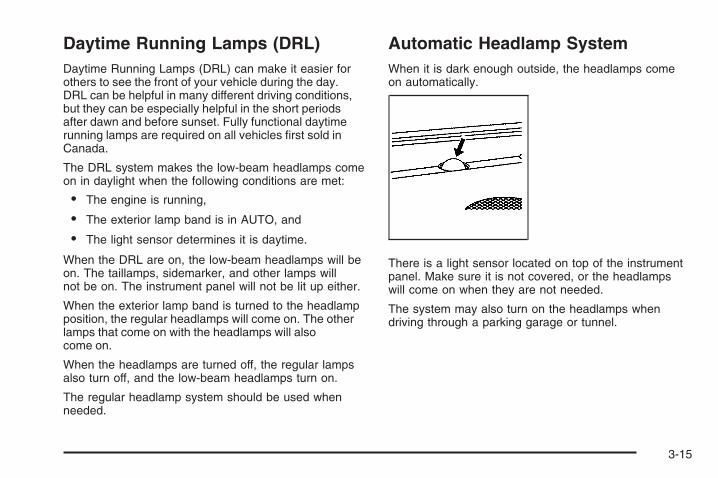
Daytime Running Lamps (DRL)Daytime Running Lamps (DRL) can make it easier forothers to see the front of your vehicle during the day.DRL can be helpful in many different driving conditions,but they can be especially helpful in the short periodsafter dawn and before sunset. Fully functional daytimerunning lamps are required on all vehicles first sold inCanada.
The DRL system makes the low-beam headlamps comeon in daylight when the following conditions are met:
• The engine is running,
• The exterior lamp band is in AUTO, and
• The light sensor determines it is daytime.
When the DRL are on, the low-beam headlamps will beon. The taillamps, sidemarker, and other lamps willnot be on. The instrument panel will not be lit up either.
When the exterior lamp band is turned to the headlampposition, the regular headlamps will come on. The otherlamps that come on with the headlamps will alsocome on.
When the headlamps are turned off, the regular lampsalso turn off, and the low-beam headlamps turn on.
The regular headlamp system should be used whenneeded.
Automatic Headlamp SystemWhen it is dark enough outside, the headlamps comeon automatically.
There is a light sensor located on top of the instrumentpanel. Make sure it is not covered, or the headlampswill come on when they are not needed.
The system may also turn on the headlamps whendriving through a parking garage or tunnel.
3-15

Instrument Panel BrightnessThis feature controls the brightness of the instrumentpanel lights.
The thumbwheel for thisfeature is located on theleft side of the steeringwheel next to the exteriorlamps control.
Turn the thumbwheel to the right to brighten the lightsor to the left to dim them.
Dome Lamp
* (Dome Lamp Override): Press this button to keepthe dome lamps and other interior lamps turned off whileany door is open. Press this button again to return it to theout position and the lamps automatically come on whenany door is opened.
+ (On/Off): Press this button to turn the domelamps on and off while the doors are closed.
Entry LightingIf the dome lamp override button is in the out position,the lamps inside the vehicle automatically come onwhen any door is opened or when the Remote KeylessEntry (RKE) unlock button is pressed. After the door isopened the lights remain on and stay on for 20 secondsafter the doors are closed, or until the key is put into theignition and turned to the ACC/ACCESSORY position.The lights will then gradually dim until it is no longer lit.
3-16

Reading LampsThe reading lamps are located on the overhead console.
To turn the reading lamps on or off, press the buttonlocated next to each lamp.
Battery Run-Down ProtectionThe battery saver feature is designed to protect yourvehicle’s battery.
If any interior or exterior lamp is left on and the ignitionis turned off, the battery rundown protection systemautomatically turns the lamp off after 10 minutes.
Accessory Power Outlet(s)The accessory power outlets can be used to connectelectrical equipment such as a cellular phone orCB radio.
The accessory power outlets are located on the rearof the center storage console and in the rear cargocompartment. There may be a power outlet located insidethe instrument panel storage area below the climatecontrols.
To use the outlets, remove the cover. When not in use,always cover the outlet with the protective cap.
Notice: Leaving electrical equipment on forextended periods will drain the battery. Alwaysturn off electrical equipment when not in use anddo not plug in equipment that exceeds the maximum20 ampere rating.
Certain electrical accessories may not be compatiblewith the accessory power outlet and could result in blownvehicle or adapter fuses. If you experience a problem,see your dealer/retailer for additional information on theaccessory power outlet.
Notice: Adding any electrical equipment to yourvehicle may damage it or keep other componentsfrom working as they should. The repairs wouldnot be covered by your warranty. Check with yourdealer/retailer before adding electrical equipment.
When adding electrical equipment, be sure to follow theinstallation instructions included with the equipment.
Notice: Improper use of the power outlet can causedamage not covered by your warranty. Do nothang any type of accessory or accessory bracketfrom the plug because the power outlets aredesigned for accessory power plugs only.
3-17

Climate ControlsAutomatic Climate Control SystemThe heating, cooling, and ventilation for the vehicle canbe controlled with this system.
Climate Control Influence on HybridOperation and Fuel EconomyTo maximize your fuel economy, use the followingsettings:
• Set the fan knob to AUTO.
• Set the air delivery knob to AUTO.
• Select an air temperature setting near 75°F (23°C).
• Select the Hybrid A/C button, if A/C is required.
Avoid using these settings that may lead to fewer autostops and to higher fuel consumption:
• Manual fan speed operation.
• Defrost mode. Only use this setting to clear thewindows.
• Extreme cold or hot air temperature settings, suchas 60°F (16°C) or 90°F (32°C).
• Normal air conditioning mode, if A/C is required.
Automatic OperationThis climate control system automatically maintains thedesired temperature inside the vehicle.
Do not cover the sensor located on the top of theinstrument panel near the windshield or the sensor grillebelow the climate control faceplate. These two sensorshelp regulate the inside air temperature.
AUTO (Automatic Fan): Turn the fan knob to AUTOfor the system to automatically adjust the fan speedto reach the desired inside temperature.
Temperature Control: Select the desired airtemperature between 60-90°F (16-32°C). Typically,the best setting is near 75°F (23°C). Choosing thecoldest or warmest temperature setting does notcause the system to heat or cool any faster.
3-18

AUTO (Automatic Air Delivery Mode): Turn theair delivery mode knob to AUTO for the system toautomatically control the direction of the airflow to helpreach the desired inside temperature.
The system automatically controls the air inlet to supplythe outside air or recirculated inside air needed to coolthe vehicle faster. The indicator light on the recirculationbutton will be lit whenever the system changes torecirculation. Press the recirculation button to changeto outside air. However, the recirculation mode mayturn back on automatically.
In cold weather, if the fan and air delivery modes arein automatic, the system starts at lower fan speeds toavoid directing cold air into the vehicle until warmer air isavailable. The climate control system directs air to thefloor, but may automatically change modes as the vehiclewarms up to maintain the chosen temperature setting.The length of time needed to warm the interior dependson the outside temperature and inside temperature ofthe vehicle.
Manual OperationIt is best to use the automatic settings to maximize fueleconomy.
To change the current fan speed, turn the left knob.
A (Fan): Turn the left knob clockwise to increasethe fan speed or counterclockwise to decrease thefan speed. To turn the fan off, turn the left knob tothe 9 position. In any setting other than off, the fanruns continuously with the ignition on. The fan must beturned on to run the air conditioning compressor. Therewill be some airflow noticeable from the various outletswhen driving, even with the fan in the off position.This is to ensure some fresh air is always availablein the vehicle. To turn off the air completely, turn thefan to 9 and select the recirculation button.
Temperature Control: Select the desired cabin airtemperature between 60-90°F (16-32°C). Typically,the best setting is near 75°F (23°C). Choosing thecoldest or warmest temperature setting does notcause the system to heat or cool any faster.
3-19

To change the current air delivery mode, use the rightknob to select one of the following:
H (Vent): This mode directs air to the instrumentpanel outlets.
) (Bi-Level): This mode divides the air between theinstrument panel outlets and the floor outlets.
6 (Floor): This mode directs most of the air to thefloor outlets with some air directed to the windshield.
When this mode is selected, the system turns therecirculation mode off. Recirculation mode cannot beselected while in floor mode. This is to help preventwindow fogging.
The right knob can also be used to select defog ordefrost mode. See “Defogging and Defrosting” later inthis section.
# (Normal Air Conditioning): Press this button toturn the air conditioning system on or off. When thisbutton is pressed, an indicator light comes on to showthat the air conditioning is activated. Normal AirConditioning (A/C) can be selected in any mode as longas the fan is on and the outside air temperature is abovefreezing. Normal A/C cannot be selected at the sametime as Hybrid Air Conditioning (A/C). A flashing indicatorlight indicates that the air conditioning compressor iscurrently not available.
When Normal A/C is selected, the climate control systemwill prevent all automatic engine start/stop operations.This will ensure the cabin comfort is maintained. See “AirConditioning and Automatic Engine Start/Stop” later inthis section.
N (Hybrid Air Conditioning): Press this button toturn the Hybrid A/C system on or off. When this button ispressed, an indicator light comes on to show that theHybrid A/C is activated. Hybrid A/C can be selected inany mode, except defrost as long as the fan is on and theoutside air temperature is above freezing. Hybrid A/Ccannot be selected at the same time as the normal airconditioning. A flashing indicator light indicates the airconditioning compressor is not available.
The Hybrid A/C works to balance fuel economy and airconditioning comfort. When Hybrid A/C is used in warmweather, the vehicle gets better fuel economy by allowingmore frequent start/stops. For additional cooling, selectNormal A/C. See “Air Conditioning and Automatic EngineStart/Stop” later in this section.
3-20

@ (Recirculation): Press this button to togglebetween recirculate and outside air modes. The indicatorlight turns on when the recirculate mode is selected.This mode can be used to prevent outside air and odorsfrom entering the vehicle or to help cool the air insidethe vehicle more quickly. Avoid using the recirculationmode during high periods of humidity and cool outsidetemperatures since this may result in increased windowfogging. If window fogging is experienced, select thedefrost mode.
Recirculation mode is not available in floor, defog ordefrost modes. If the button is selected in these modes,the indicator will flash. This helps prevent window foggingand moisture building up inside the vehicle.
Defogging and DefrostingFog on the inside of windows is a result of high humidity(moisture) condensing on the cool window glass. Thiscan be minimized if the climate control system is usedproperly. There are two modes to clear fog or frost fromthe windshield and side windows. Use the defog modeto clear the windows of fog or moisture and warm thepassengers. Use the defrost mode to remove fog or frostfrom the windshield more quickly. For best results, clearall snow and ice from the windshield before defrosting.
Manually turn the right knob to select the defog ordefrost mode.
- (Defog): This mode directs air to the windshield,side window outlets and floor outlets. When this mode isselected, the system turns the recirculation mode off andruns the air conditioning compressor unless the outsideair is at or below freezing. The recirculation mode cannotbe selected while in defog mode. This helps preventwindow fogging and moisture building up inside thevehicle.
0 (Defrost): This mode directs most of the air to thewindshield, with some air directed to the side windowoutlets and the floor outlets. When this mode is selected,the system turns the recirculation mode off automaticallyand runs the air conditioning compressor unless theoutside air is at or below freezing. The recirculation modecannot be selected while in defrost mode. This helpsprevent window fogging and moisture building up insidethe vehicle. In this mode, the climate control systemprevents all automatic engine start/stop operations.This ensures the best defrost performance.
3-21

Rear Window DefoggerThe rear window defogger uses a warming grid toremove fog from the rear window.
The rear window defogger will only work when theignition is in ON/RUN.
< (Rear Window Defogger): Press this button toturn the rear window defogger on or off. An indicatorlight on the button comes on to show that the rearwindow defogger is activated.
The rear window defogger stays on for about 10 minutesif the vehicle remains at slower vehicle speeds or untilthe button is pressed, or unless the ignition is turnedto ACC/ACCESSORY or LOCK/OFF. If turned on again,the defogger only runs for about five minutes beforeturning off again. At higher vehicle speeds, the defoggermay stay on continuously. The defogger can alwaysbe turned off by pressing the button again or by turningoff the ignition.
Notice: Do not use anything sharp on the insideof the rear window. If you do, you could cut ordamage the warming grid, and the repairs wouldnot be covered by the vehicle warranty. Do notattach a temporary vehicle license, tape, a decalor anything similar to the defogger grid.
Air Conditioning and Engine Start/StopOn hot days, use the automatic fan and automatic airdelivery mode settings and the vehicle will reach thedesired temperature more quickly. The desired fan andair delivery mode settings can still be adjusted manually.Open the windows to let the hot inside air escape, thenclose them. This helps reduce the time it takes for thevehicle to cool down and helps the system to operatemore efficiently.
When either the Normal A/C or Hybrid A/C modes areactive, the air conditioning system removes moisturefrom the air, so a small amount of water may drip underthe vehicle while idling or after turning off the engine.This is normal.
The use of Normal A/C causes the engine to keeprunning while the vehicle is at a complete stop to allowthe climate control system to continue cooling.
The use of Hybrid A/C allows automatic engine start/stop operations while the vehicle is at a complete stop.The air conditioning compressor can not run whenthe engine is not running, resulting in reduced coolingperformance. The climate control system may keep theengine running or restart the engine during a stop tocontinue cooling. Selecting the Normal A/C button forcesthe engine and air conditioning compressor to restartautomatically. For more information about EngineStart/Stop operation, see Starting the Engine(Automatic Engine Start/Stop) on page 2-18.
3-22

Outlet AdjustmentUse the louvers located on the air outlets to change thedirection of the airflow.
Operation Tips• Clear away any ice, snow, or leaves from the air
inlets at the base of the vehicle that may blockthe flow of air into your vehicle.
• Do not use any non-GM approved hood deflectorsthat could adversely affect the performance of thesystem.
• Keep the path under the front seats clear of objectsto help circulate the air inside of your vehicle moreeffectively.
Passenger Compartment Air FilterThe filter removes dust, pollen, and other airborneirritants from outside air which is drawn into the vehicle.
The filter should be replaced as part of routinescheduled maintenance. See Scheduled Maintenanceon page 6-4 for replacement intervals. To find out whattype of filter to use, see Maintenance Replacement Partson page 6-13.
The passenger compartment air filter can be accessedby removing the entire glove box.
1. Remove the six screws from around the glove boxand detach the three inner clips from the glove box.
2. Lower the loosened glove box housing.
3-23
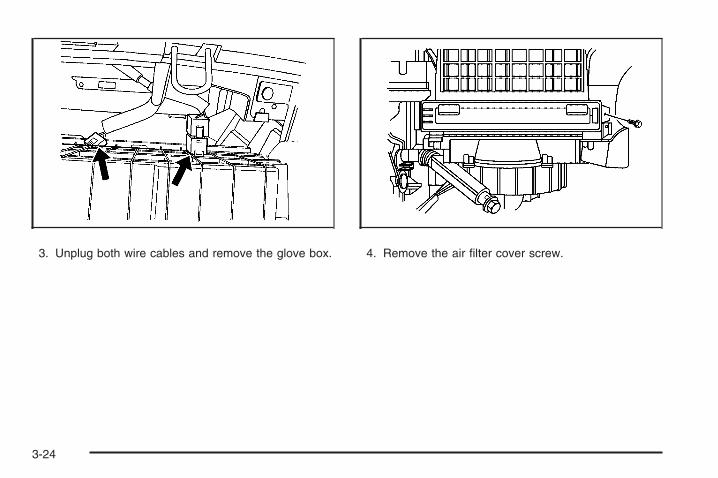
3. Unplug both wire cables and remove the glove box. 4. Remove the air filter cover screw.
3-24
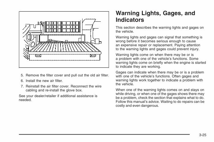
5. Remove the filter cover and pull out the old air filter.
6. Install the new air filter.
7. Reinstall the air filter cover. Reconnect the wirecabling and re-install the glove box.
See your dealer/retailer if additional assistance isneeded.
Warning Lights, Gages, andIndicatorsThis section describes the warning lights and gages onthe vehicle.
Warning lights and gages can signal that something iswrong before it becomes serious enough to causean expensive repair or replacement. Paying attentionto the warning lights and gages could prevent injury.
Warning lights come on when there may be or isa problem with one of the vehicle’s functions. Somewarning lights come on briefly when the engine is startedto indicate they are working.
Gages can indicate when there may be or is a problemwith one of the vehicle’s functions. Often gages andwarning lights work together to indicate a problem withthe vehicle.
When one of the warning lights comes on and stays onwhile driving, or when one of the gages shows there maybe a problem, check the section that explains what to do.Follow this manual’s advice. Waiting to do repairs can becostly and even dangerous.
3-25
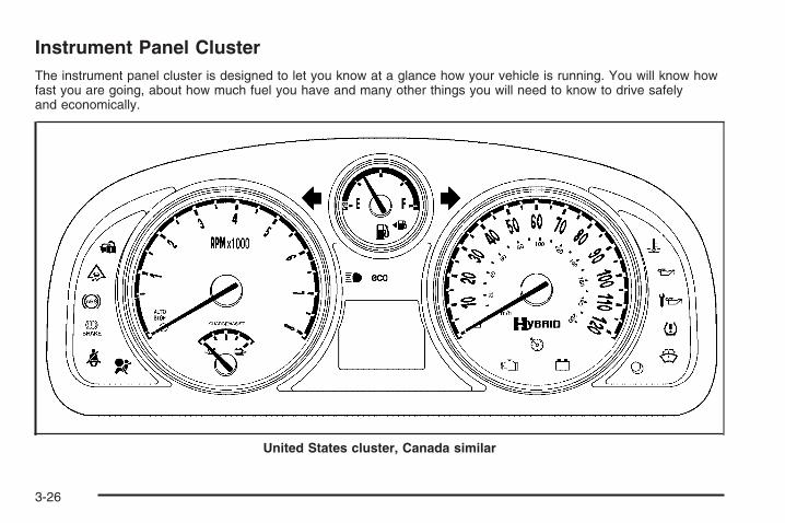
Instrument Panel ClusterThe instrument panel cluster is designed to let you know at a glance how your vehicle is running. You will know howfast you are going, about how much fuel you have and many other things you will need to know to drive safelyand economically.
United States cluster, Canada similar
3-26

Speedometer and OdometerThe speedometer lets you see your speed in both milesper hour (mph) and kilometers per hour (km/h).
The odometer shows how far your vehicle has beendriven, in either miles or kilometers.
Your vehicle has a tamper-resistant odometer. If yourvehicle needs a new odometer installed, the new one willbe set to the mileage total of the old odometer. If this isnot possible, it will be set at zero and a label must beput on the driver’s door to show the old mileage readingwhen the new odometer was installed. If the mileageis unknown, the label should then indicate “previousmileage unknown”.
Trip OdometerYour trip odometer is located on the instrument paneland shows how far your vehicle has been driven since thetrip odometer was last reset. To reset the trip odometerto zero, press and hold the trip/reset button on thespeedometer for about two seconds. Press the trip/resetbutton to switch between the trip odometer and odometer.
Tachometer
The tachometerdisplays the enginespeed in revolutionsper minute (rpm).
The auto stop indicator is located at the bottom of thetachometer. For more information see Auto Stop Modeon page 3-42.
U.S. shown,Canada similar
3-27

Safety Belt Reminders
Safety Belt Reminder LightWhen the engine is started, a chime will come on forseveral seconds to remind people to fasten their safetybelts, unless the driver’s safety belt is already buckled.
The safety belt light willalso come on and stayon for several seconds,then it will flash forseveral more.
This chime and light is repeated if the driver remainsunbuckled and the vehicle is in motion. If the driver’s beltis already buckled, neither the chime nor the light willcome on.
Passenger Safety Belt Reminder LightSeveral seconds after the engine is started, a chime willsound for several seconds to remind the front passengerto buckle their safety belt. This would only occur if thepassenger airbag is enabled. See Passenger SensingSystem on page 1-63 for more information. Thepassenger safety belt light, located on the instrumentpanel, will come on and stay on for several secondsand then flash for several more.
This chime and light arerepeated if the passengerremains unbuckled andthe vehicle is in motion.
If the passenger’s safety belt is buckled, neither thechime nor the light will come on.
3-28

Airbag Readiness LightThere is an airbag readiness light on the instrumentpanel cluster, which shows the airbag symbol.The system checks the airbag’s electrical system formalfunctions. The light tells you if there is an electricalproblem. The system check includes the airbag sensor,the pretensioners, the airbag modules, the wiring andthe crash sensing and diagnostic module. For moreinformation on the airbag system, see Airbag Systemon page 1-53.
This light will comeon when you start yourvehicle, and it will flash fora few seconds. The lightshould go out and thesystem is ready.
If the airbag readiness light stays on after you start thevehicle or comes on when you are driving, your airbagsystem may not work properly. Have your vehicleserviced right away.
{CAUTION:
If the airbag readiness light stays on after youstart your vehicle, it means the airbag systemmay not be working properly. The airbags inyour vehicle may not inflate in a crash, or theycould even inflate without a crash. To helpavoid injury to yourself or others, have yourvehicle serviced right away.
The airbag readiness light should flash for afew seconds when you start the engine. If the lightdoes not come on then, have it fixed immediately.If there is a problem with the airbag system, an airbagDriver Information Center (DIC) message may also comeon. See DIC Warnings and Messages on page 3-50 formore information.
3-29

Passenger Airbag Status IndicatorYour vehicle has the passenger sensing system.Your instrument panel has a passenger airbag statusindicator.
When you start the vehicle, the passenger airbag statusindicator will light ON and OFF, or the symbol for onand off, for several seconds as a system check. Then,after several more seconds, the status indicator willlight either ON or OFF, or either the on or off symbol tolet you know the status of the right front passenger’sfrontal airbag.
If the word ON or the on symbol is lit on the passengerairbag status indicator, it means that the right frontpassenger’s frontal airbag is enabled (may inflate).
{CAUTION:
If the on indicator comes on when you have arear-facing child restraint installed in the rightfront passenger’s seat, it means that thepassenger sensing system has not turned offthe passenger’s frontal airbag. A child in arear-facing child restraint can be seriouslyinjured or killed if the right front passenger’sairbag inflates. This is because the back of therear-facing child restraint would be very closeto the inflating airbag. Do not use a rear-facingchild restraint in the right front passenger’sseat if the airbag is turned on.
United States Canada
3-30

{CAUTION:
Even though the passenger sensing system isdesigned to turn off the right front passenger’sfrontal airbag if the system detects a rear-facingchild restraint, no system is fail-safe, and noone can guarantee that an airbag will not deployunder some unusual circumstance, eventhough it is turned off. We recommend thatrear-facing child restraints be secured in therear seat, even if the airbag is off.
If the word OFF or the off symbol is lit on the airbagstatus indicator, it means that the passenger sensingsystem has turned off the right front passenger’s frontalairbag. See Passenger Sensing System on page 1-63for more on this, including important safety information.
If, after several seconds, both status indicator lightsremain on, or if there are no lights at all, there maybe a problem with the lights or the passenger sensingsystem. See your dealer/retailer for service.
{CAUTION:
If the airbag readiness light in the instrumentpanel cluster ever comes on and stays on, itmeans that something may be wrong with theairbag system. If this ever happens, have thevehicle serviced promptly, because anadult-size person sitting in the right frontpassenger’s seat may not have the protectionof the airbag(s). See Airbag Readiness Lighton page 3-29 for more on this, includingimportant safety information.
3-31

Charging System Light
This light will come onbriefly when you turn on theignition key, but the engineis not running, as a checkto show you it is working.
It should go out once the engine is running. If it stayson, or comes on while driving, there could be a problemwith the charging system. A charging system DriverInformation Center (DIC) message may also appear.See DIC Warnings and Messages on page 3-50 formore information. This light could indicate that there areproblems with a generator drive belt, or that there is anelectrical problem. Have it checked right away. If youmust drive a short distance with the light on, be certainto turn off all the accessories, such as the radio and airconditioner.
Brake System Warning Light
This light should come on briefly when the engine isstarted.
If it does not come on, have it fixed so it will be ready towarn you if there is a problem.
When the ignition is on, the brake system warninglight will come on when the parking brake is set.The light will stay on if the parking brake does notrelease fully. If it stays on after the parking brake isfully released, there is a brake problem. Have yourbrake system inspected immediately.
United States Canada
3-32

If the light comes on while driving, a chime will sound.Pull off the road and stop. The pedal might be harder topush or go closer to the floor. It might also take longerto stop. If the light is still on, have the vehicle towedfor service. See Towing Your Vehicle on page 4-28.
{CAUTION:
Your brake system may not be workingproperly if the brake system warning light ison. Driving with the brake system warning lighton can lead to an accident. If the light is stillon after you have pulled off the road andstopped carefully, have the vehicle towedfor service.
Anti-lock Brake System (ABS)Warning Light
For vehicles withthe Antilock BrakeSystem (ABS), this lightcomes on briefly whenthe engine is started.
That is normal. If the light does not come on then, haveit fixed so it will be ready to warn you if there is a problem.
If the ABS light stays on, turn the ignition off, if the lightcomes on when you are driving, stop as soon as it issafely possible and turn the ignition off. Then start theengine again to reset the system. If the ABS light stillstays on, or comes on again while you are driving,your vehicle needs service. If the regular brake systemwarning light is not on, your vehicle still has brakes, butnot antilock brakes. If the regular brake system warninglight is also on, your vehicle does not have antilockbrakes and there is a problem with the regular brakes.See Brake System Warning Light on page 3-32.
For vehicles with a Driver Information Center (DIC),see DIC Warnings and Messages on page 3-50 forall brake related DIC messages.
3-33

Traction Control System (TCS)Warning Light
The Traction ControlSystem (TCS) warninglight may come on forthe following reasons:
• The system is turned off by pressing the tractioncontrol button located above the audio system onthe instrument panel. The warning light will comeon and stay on. Press the button again, to turn thesystem back on. The warning light should go off.See Traction Control System (TCS) on page 4-7 formore information.
• An engine and brake system problem related totraction control makes the TCS turn off.
If the TCS warning light comes on and stays on for anextended period of time when the system is turnedon, your vehicle needs service.
Electronic Stability ProgramIndicator Light
This comes on brieflywhen the engine is started.
It flashes while the Electronic Stability Program (ESP) orthe Traction Control System (TCS) is working. This lightwill come on when the ESP has been turned off and ifthere is a problem with the ESP or the TCS. See TractionControl System (TCS) on page 4-7 and ElectronicStability Program on page 4-8 for more information.
3-34

Engine Coolant TemperatureWarning LightThis light comes on briefly when starting the vehicleas a system check. If it does not, take the vehicle toyour dealer/retailer for service.
If this light comes on andstays lit, the engine hasoverheated.
If this happens pull over and see Engine Overheatingon page 5-23 for more information.
Notice: Driving with the engine coolant temperaturewarning light on could cause your vehicle tooverheat. See Engine Overheating on page 5-23.Your vehicle could be damaged, and it might notbe covered by your warranty. Never drive withthe engine coolant temperature warning light on.
Tire Pressure Light
The tire pressure lightcomes on briefly when theengine is started.
It provides information about tire pressures and the TirePressure Monitoring System.
When the Light is SolidThis indicates that one or more of your tires aresignificantly underinflated.
Stop and check the tires as soon as it is safe to do,and inflate them to the proper pressure. See Tireson page 5-47 for more information.
When the Light Flashes First andThen is SolidThis indicates that there may be a problem with the TirePressure Monitor System. The light flashes for abouta minute and then stays solid for the remainder ofthe ignition cycle. This sequence will repeat with everyignition cycle. See Tire Pressure Monitor System onpage 5-54 for more information.
3-35

Malfunction Indicator LampCheck Engine LightA computer system called OBD II (On-BoardDiagnostics-Second Generation) monitors operationof the fuel, ignition, and emission control systems.It makes sure that emissions are at acceptable levelsfor the life of the vehicle, helping to produce a cleanerenvironment.
The check engine lightcomes on to indicate thatthere is an OBD II problemand service is required.
Malfunctions often are indicated by the system beforeany problem is apparent. This can prevent more seriousdamage to your vehicle. This system is also designedto assist your service technician in correctly diagnosingany malfunction.
Notice: If you keep driving your vehicle with thislight on, after a while, the emission controls mightnot work as well, your vehicle’s fuel economy mightnot be as good, and the engine might not run assmoothly. This could lead to costly repairs that mightnot be covered by your warranty.
Notice: Modifications made to the engine,transmission, exhaust, intake, or fuel system ofyour vehicle or the replacement of the original tireswith other than those of the same Tire PerformanceCriteria (TPC) can affect your vehicle’s emissioncontrols and can cause this light to come on.Modifications to these systems could lead to costlyrepairs not covered by your warranty. This couldalso result in a failure to pass a required EmissionInspection/Maintenance test. See Accessoriesand Modifications on page 5-3.
This light comes on, as a check to show it is working,when the ignition is turned ON/RUN but the engine is notrunning. If the light does not come on, have it repaired.This light also comes on during a malfunction inone of two ways:
• Light Flashing — A misfire condition has beendetected. A misfire increases vehicle emissionsand could damage the emission control systemon your vehicle. Diagnosis and service mightbe required.
• Light On Steady — An emission control systemmalfunction has been detected on your vehicle.Diagnosis and service might be required.
3-36

If the Light is FlashingThe following can prevent more serious damage to yourvehicle:
• Reduce vehicle speed.
• Avoid hard accelerations.
• Avoid steep uphill grades.
• If you are towing a trailer, reduce the amount ofcargo being hauled as soon as it is possible.
If the light stops flashing and remains on steady,see “If the Light Is On Steady” following.
If the light continues to flash, when it is safe to do so,stop the vehicle. Find a safe place to park the vehicle.Turn the ignition off, wait at least 10 seconds, and restartthe engine. If the light remains on steady, see “If theLight Is On Steady” following. If the light is still flashing,follow the previous steps and see your dealer/retailerfor service as soon as possible.
If the Light Is On SteadyYou might be able to correct the emission systemmalfunction by considering the following:
Did you recently put fuel into your vehicle?
If so, reinstall the fuel cap, making sure to fullyinstall the cap. See Filling the Tank on page 5-8.The diagnostic system can determine if the fuel cap
has been left off or improperly installed. A loose ormissing fuel cap allows fuel to evaporate into theatmosphere. A few driving trips with the cap properlyinstalled should turn the light off.
Did you just drive through a deep puddle of water?
If so, your vehicle’s electrical system might be wet.The condition is usually corrected when the electricalsystem dries out. A few driving trips should turn thelight off.
Have you recently changed brands of fuel?
If so, be sure to fuel your vehicle with quality fuel. SeeGasoline Octane on page 5-6. Poor fuel quality causesthe engine not to run as efficiently as designed. Youmight notice this as stalling after start-up, stalling whenyou put the vehicle into gear, misfiring, hesitation onacceleration, or stumbling on acceleration — theseconditions might go away once the engine is warmed up.This will be detected by the system and cause the light toturn on.
If you experience one or more of these conditions,change the fuel brand you use. It will require at leastone full tank of the proper fuel to turn the light off.
If none of the above steps have made the light turn off,your dealer/retailer can check the vehicle. Your dealer/retailer has the proper test equipment and diagnostictools to fix any mechanical or electrical problems thatmight have developed.
3-37

Emissions Inspection and MaintenanceProgramsSome state/provincial and local governments have ormight begin programs to inspect the emission controlequipment on your vehicle. Failure to pass thisinspection could prevent you from getting a vehicleregistration.
Here are some things you need to know to help yourvehicle pass an inspection:
Your vehicle will not pass this inspection if the checkengine light is on or not working properly.
Your vehicle will not pass this inspection if the OBD(on-board diagnostic) system determines that criticalemission control systems have not been completelydiagnosed by the system. The vehicle would beconsidered not ready for inspection. This can happen ifyou have recently replaced the battery or if the batteryhas run down. The diagnostic system is designed toevaluate critical emission control systems during normaldriving. This can take several days of routine driving.If you have done this and your vehicle still does not passthe inspection for lack of OBD system readiness, yourdealer/retailer can prepare the vehicle for inspection.
Oil Pressure Light
This light stays on after theengine is started, or comeson while driving, if thereis a low engine oil problem.
This light indicates that the engine is not receivingenough oil. The engine could be low on oil, or couldhave some other oil problem. Have it fixed immediately.
The oil pressure light also comes on when the ignitionis on but the engine is not running, as a test to show itis working. It will go out when the ignition is turnedto START. If the light does not come on briefly whilethe ignition is on, the fuse or bulb might need tobe replaced. See your dealer/retailer for service.
3-38

{CAUTION:
Do not keep driving if the oil pressure is low.If you do, your engine can become so hot thatit catches fire. You or others could be burned.Check your oil as soon as possible and haveyour vehicle serviced.
Notice: Lack of proper engine oil maintenancemay damage the engine. The repairs would notbe covered by your warranty. Always followthe maintenance schedule in this manual forchanging engine oil.
Change Engine Oil Light
This light means thatservice is required foryour vehicle.
See Scheduled Maintenance on page 6-4 and EngineOil on page 5-13 for more information.
After the engine oil is changed the engine oil life systemneeds to be reset in order to turn off this light. See EngineOil Life System on page 5-16 for more information.
3-39

Security Light
For information regardingthis light and the vehicle’ssecurity system, seeContent Theft-Deterrenton page 2-13.
Cruise Control Light
This light comes onwhenever the cruisecontrol is set.
The light goes out when the cruise control is turned off.See Cruise Control on page 3-11 for more information.
Highbeam On Light
This light comes on whenthe high-beam headlampsare in use.
See Headlamp High/Low-Beam Changer on page 3-8for more information.
Low Washer Fluid Warning Light
This light comes on brieflywhen the engine is started.
It also comes on when the windshield washer fluid islow. See Windshield Washer Fluid on page 5-29for more information.
3-40

Fuel Gage
When the ignition is on, the fuel gage shows about howmuch fuel is in the fuel tank.
When the indicator nears empty, the low fuel lightwill comes on. There still is a little fuel left, but youshould get more soon. See Low Fuel Warning Lighton page 3-42 for more information.
Four things that can happen but do not mean the fuelgage is not functioning properly are:
• At the service station, the fuel pump shuts offbefore the gage reads full.
• It takes a little more or less fuel to fill up than thefuel gage indicates.
• The gage moves a little when the vehicle turns acorner or accelerates.
• The gage takes a few seconds to stabilize after theignition is turned on, and goes back to empty afterthe ignition is turned off.
For the fuel tank capacity, see Capacities andSpecifications on page 5-98.
United States Canada
3-41

Low Fuel Warning Light
The light next to the fuelgage comes on brieflywhen you are startingthe engine.
It also comes on when the vehicle is low on fuel.After fuel is added, the light should go off. If it does notcome on as you start the engine take the vehicle toyour dealer/retailer for service.
Auto Stop Mode
This mark on the tachometer signifies that the engine isin Auto Stop mode which is a fuel saving operation.
When the vehicle is off, the tachometer needle movesto OFF. If the driver’s door is opened while in Auto Stop,a chime will sound.
United States Canada
3-42

Charge/Assist Gage
The CHARGE/ASSISTgage displays the charge(current) into and outof the hybrid battery.
While the electric motor is performing an automaticrestart of the engine, or while it is assisting the engine,as in maximum acceleration, the needle moves to theASSIST range, located on the right side of the gage.The needle moves to the CHARGE range when theelectric motor operates as a generator to performregenerative braking, as the vehicle slows down.See Regenerative Braking on page 2-26 for moreinformation. The needle also moves into the CHARGErange if the hybrid control system identifies it is anefficient time to charge the hybrid battery.
If the hybrid battery or other hybrid components arevery hot or cold, the CHARGE and ASSIST functionsmay be suspended until the component temperaturesare normal.
Fuel Economy Light
This light comes on whenthe vehicle is achieving fueleconomy close to its ratedperformance.
Driving habits that improve fuel economy increases thetime that the fuel economy light is on.
To turn the fuel economy light off or on, press thetrip/reset button until the HOLD STEM TO SET ECO(Economy) DIC message is displayed. Then press andhold the trip/reset button until off or on is selected.For more information see Trip Odometer on page 3-27and DIC Operation and Displays on page 3-44.
3-43

Driver Information Center (DIC)Your vehicle has a Driver Information Center (DIC).
All information appears in the DIC display located in theinstrument panel cluster.
The DIC comes on when the ignition is on. After a shortdelay, the DIC displays the information that was lastdisplayed before the engine was turned off.
The DIC displays trip, fuel, and vehicle systeminformation, and warning messages if a system problemis detected.
The DIC also displays the compass direction, outside airtemperature, and shift position indicator at the top of theDIC display. If there is a problem with the system thatcontrols the temperature display, the numbers will bereplaced with dashes. If this occurs, have the vehicleserviced by your dealer/retailer. If an abnormaltemperature reading is displayed for an extended periodof time, consult your dealer/retailer. Under certaincircumstances, especially when the engine is idling,a delay updating the temperature display is normal.
See DIC Compass on page 3-48 and AutomaticTransmission Operation on page 2-23 for moreinformation.
DIC Operation and DisplaysThe DIC has different displays which can be accessedby pressing the reset stem located on the instrumentpanel cluster. These displays are explained in thefollowing section. To scroll through the availablefunctions, press and release the reset stem.
ODOMETERPress and release the reset stem until ODOMETERdisplays. This display shows the distance the vehiclehas been driven in either miles (mi) or kilometers (km).
TRIPPress and release the reset stem until TRIP displays.This display shows the current distance traveled in eithermiles (mi) or kilometers (km) since the last reset forthe trip odometer.
To reset the trip odometer to zero, press and hold thereset stem while the trip odometer is displayed.
3-44

RANGEPress and release the reset stem until RANGE isdisplayed. The RANGE display will only be availablewhen the vehicle is not in PARK (P).
This display shows the approximate number ofremaining miles (mi) or kilometers (km) the vehiclecan be driven without refueling.
The fuel range estimate is based on an average ofthe vehicle’s fuel economy over recent driving historyand the amount of fuel remaining in the fuel tank.This estimate will change if driving conditions change.For example, if driving in traffic and making frequentstops, this display may read one number, but ifthe vehicle is driven on a freeway, the number maychange even though the same amount of fuel is in thefuel tank. This is because different driving conditionsproduce different fuel economies. Generally, freewaydriving produces better fuel economy than city driving.
If your vehicle is low on fuel, the FUEL LEVEL LOWmessage displays. See “FUEL LEVEL LOW” underDIC Warnings and Messages on page 3-50 for moreinformation.
INSTANT (Instantaneous) FUEL ECONOMYPress and release the reset stem INSTANT FUELECONOMY displays. The INSTANT FUEL ECONOMYdisplay will only be available when the vehicle is notin PARK (P).
This display shows the current fuel economy at aparticular moment and will change frequently as drivingconditions change. This display shows the instantaneousfuel economy in miles per gallon (mpg) or liters per100 kilometers (L/100 km). This display cannot be reset.
AVERAGE FUEL ECONOMYPress and release the reset stem AVERAGE FUELECONOMY displays. The AVERAGE FUEL ECONOMYdisplay will only be available when the vehicle is notin PARK (P).
This display shows the approximate average miles pergallon (mpg) or liters per 100 kilometers (L/100 km).This number is calculated based on the number of mpg(L/100 km) recorded since the last time this displaywas reset. To reset this display to zero, press and holdthe reset stem.
3-45

OIL LIFEPress and release the reset stem until OIL LIFEREMAINING displays. The OIL LIFE display will onlybe available when the vehicle is in PARK (P). This displayshows an estimate of the oil’s remaining useful life. If OILLIFE REMAINING 99% appears on the display, thatmeans 99% of the current oil life remains. The engine oillife system will alert you to change the oil on a scheduleconsistent with your driving conditions.
When the remaining oil life is low, the CHANGEENGINE OIL SOON message will appear on thedisplay. See “CHANGE ENGINE OIL SOON” underDIC Warnings and Messages on page 3-50. Changethe oil as soon as possible. See Engine Oil on page 5-13.In addition to the engine oil life system monitoring theoil life, additional maintenance is recommended in theMaintenance Schedule in this manual. See ScheduledMaintenance on page 6-4 for more information.
Remember, reset the OIL LIFE after each oil change.It will not reset itself. Also, be careful not to reset the OILLIFE accidentally at any time other than when the oilhas just been changed. It cannot be reset accuratelyuntil the next oil change. To reset the engine oillife system, see Engine Oil Life System on page 5-16.
UNITSPress and release the reset stem until UNITS displays.This display selects the units of measurement. Oncein this display, press the reset stem to select ENGLISH(default) or METRIC.
HOLD STEM TO SET LANGUAGEPress and release the reset stem until HOLD STEM TOSET LANGUAGE displays. The HOLD STEM TO SETLANGUAGE display will only be available when thevehicle is in PARK (P). This display selects the languagein which the DIC messages will appear. Once in thisdisplay, press the reset stem to select ENGLISH(default), SPANISH, or FRENCH.
Tire PressureThe pressure for each tire can be viewed in the DIC.The tire pressure will be shown in either pounds persquare inch (psi) or kilopascals (kPa). Press and releasethe reset stem until the DIC displays FRONT TIRESLEFT ## PSI (kPa) RIGHT ## PSI (kPa). Press andrelease the reset stem again until the DIC displays REARTIRES LEFT ## PSI (kPa) RIGHT ## PSI (kPa).If a low or high tire pressure condition is detected by thesystem while driving, a message advising you to checkthe pressure in a specific tire will appear in the display.See Inflation - Tire Pressure on page 5-52 and DICWarnings and Messages on page 3-50 for moreinformation.
3-46

If the tire pressure display shows dashes instead of avalue, there may be a problem with your vehicle. If thisconsistently occurs, see your dealer/retailer for service.
HOLD STEM TO RELEARN REMOTE KEYThis display matches Remote Keyless Entry (RKE)transmitters to your vehicle. To match a transmitter:
1. Put the vehicle in PARK (P).
2. Press and release the reset stem until HOLD STEMTO RELEARN REMOTE KEY displays.
3. Press and hold the reset stem until REMOTE KEYLEARNING ACTIVE is displayed.
4. Press and hold the lock and unlock buttons onthe first transmitter at the same time for about15 seconds.A chime will sound indicating that the transmitteris matched and REMOTE KEY LEARNINGCOMPLETE will be displayed.
5. To match additional transmitters at this time, repeatStep 4.Each vehicle can have a maximum ofeight transmitters matched to it.
6. To exit the programming mode, cycle the key toLOCK/OFF.
HOLD STEM TO SET ECO (Economy)Press and release the reset stem until HOLD STEM TOSET ECO (Economy) displays. The HOLD STEM TOSET ECO display will only be available when the vehicleis in PARK (P). This display turns the fuel economy lighton or off. Once in this display, press the reset stem toselect ON (default) or OFF. See Fuel Economy Light onpage 3-43 for more information.
HOLD STEM TO CALIBRATE COMPASSPress and release the reset stem until HOLD STEM TOCALIBRATE COMPASS displays. The compass canbe manually calibrated. To calibrate the compassthrough the DIC, see DIC Compass on page 3-48.
HOLD STEM TO SET COMPASS ZONEPress and release the reset stem until HOLD STEMTO SET COMPASS ZONE displays. To changethe compass zone through the DIC, see DIC Compasson page 3-48.
3-47

DIC CompassYour vehicle has a compass in the Driver InformationCenter (DIC).
Compass ZoneThe zone is set to zone eight upon leaving the factory.Your dealer/retailer will set the correct zone for yourlocation.
Under certain circumstances, such as during a longdistance cross-country trip or moving to a new state orprovince, it will be necessary to compensate for compassvariance by resetting the zone through the DIC if the zoneis not set correctly.
Compass variance is the difference between the earth’smagnetic north and true geographic north. If the compassis not set to the zone where you live, the compass maygive false readings. The compass must be set to thevariance zone in which the vehicle is traveling.
To adjust for compass variance, use the followingprocedure:
Compass Variance (Zone) Procedure1. Do not set the compass zone when the vehicle is
moving. Only set it when the vehicle is in PARK (P).Press the reset stem until HOLD STEM TO SETCOMPASS ZONE: ## displays.
2. Find the vehicle’s current location and variancezone number on the map.Zones 1 through 15 are available.
3. Press and hold the reset stem to scroll through andselect the appropriate variance zone.To set the zone, release the reset stem when thecorrect zone is displayed.
4. Press the reset stem until the vehicle heading,for example, N for North, is displayed in the DIC.
5. If calibration is necessary, calibrate the compass.See “Compass Calibration Procedure” following.
3-48
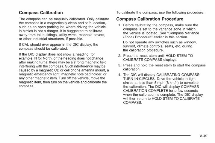
Compass CalibrationThe compass can be manually calibrated. Only calibratethe compass in a magnetically clean and safe location,such as an open parking lot, where driving the vehiclein circles is not a danger. It is suggested to calibrateaway from tall buildings, utility wires, manhole covers,or other industrial structures, if possible.
If CAL should ever appear in the DIC display, thecompass should be calibrated.
If the DIC display does not show a heading, forexample, N for North, or the heading does not changeafter making turns, there may be a strong magnetic fieldinterfering with the compass. Such interference may becaused by a magnetic CB or cell phone antenna mount, amagnetic emergency light, magnetic note pad holder, orany other magnetic item. Turn off the vehicle, move themagnetic item, then turn on the vehicle and calibrate thecompass.
To calibrate the compass, use the following procedure:
Compass Calibration Procedure1. Before calibrating the compass, make sure the
compass is set to the variance zone in whichthe vehicle is located. See “Compass Variance(Zone) Procedure” earlier in this section.Do not operate any switches such as window,sunroof, climate controls, seats, etc. duringthe calibration procedure.
2. Press the reset stem until HOLD STEM TOCALIBRATE COMPASS displays.
3. Press and hold the reset stem to start the compasscalibration.
4. The DIC will display CALIBRATING COMPASS:TURN IN CIRCLES. Drive the vehicle in tightcircles at less than 5 mph (8 km/h) to completethe calibration. The DIC will display COMPASSCALIBRATION COMPLETE for a few secondswhen the calibration is complete. The DIC displaywill then return to HOLD STEM TO CALIBRATECOMPASS.
3-49

DIC Warnings and MessagesMessages are displayed on the DIC to notify the driverthat the status of the vehicle has changed and that someaction may be needed by the driver to correct thecondition. Multiple messages may appear one afteranother.
Some messages may not require immediate action, butyou can press the reset stem on the instrument panelcluster to acknowledge that you received the messagesand to clear them from the display.
Some messages cannot be cleared from the DIC displaybecause they are more urgent. These messages requireaction before they can be cleared. Take any messagesthat appear on the display seriously and remember thatclearing the messages will only make the messagesdisappear, not correct the problem.
The following are the possible messages that can bedisplayed and some information about them.
BATTERY SAVER ACTIVEThis message displays when the charging systemdetects that the battery is being drained. You may noticethat the vehicle attempts to reduce the drain for you byturning off accessories, such as interior fans, reardefogger, and heated seats. Turn off all accessories.If the vehicle is not running, start and run the enginefor at least 10 minutes to allow the battery to recharge.If the engine is running and the condition persists,see your dealer/retailer immediately.
BUCKLE PASSENGER SEATBELTThis message reminds you to buckle the passenger’ssafety belt. See Passenger Sensing System onpage 1-63.
This message displays and a chime sounds whenthe ignition is on, the driver’s safety belt is buckled, thepassenger’s safety belt is unbuckled with the passengerairbag enabled, and the vehicle is in motion. You shouldhave the passenger buckle their safety belt.
This reminder will be repeated if the ignition is on,the vehicle is in motion, the driver is buckled and thepassenger is still unbuckled, and the passenger airbagis enabled. If the passenger’s safety belt is alreadybuckled, this message and chime will not come on.
3-50

BUCKLE SEATBELTThis message reminds you to buckle the driver’ssafety belt.
This message displays and a chime sounds when theignition is on, the driver’s safety belt is unbuckled,and the vehicle is in motion. You should buckle yoursafety belt.
If the driver remains unbuckled when the ignition ison and the vehicle is in motion, the reminder will berepeated. If the driver’s safety belt is already buckled,this message and chime will not come on.
This message is an additional reminder to the SafetyBelt Reminder Light in the instrument panel cluster.See Safety Belt Reminders on page 3-28.
CALIBRATING COMPASS: TURN INCIRCLESThis message displays when calibrating the compass.Drive the vehicle in circles at less than 5 mph (8 km/h)to complete the calibration. See DIC Compass onpage 3-48.
CHANGE ENGINE OIL SOONThis message displays when service is required for thevehicle. See your dealer/retailer. See Engine Oil onpage 5-13 and Scheduled Maintenance on page 6-4for more information.
Acknowledging this message will not reset the OIL LIFEREMAINING display. That must be done at the OILLIFE screen. See “OIL LIFE” under DIC Operation andDisplays on page 3-44 and Engine Oil Life Systemon page 5-16 for more information.
CHANGE TRANSMISSION FLUID
Notice: Use of the incorrect automatic transmissionfluid may damage your vehicle, and the damagesmay not be covered by your warranty. Alwaysuse the automatic transmission fluid listed inRecommended Fluids and Lubricants on page 6-12.
This message displays when the life of thetransmission fluid has expired and it should bechanged. See Scheduled Maintenance on page 6-4and Recommended Fluids and Lubricants on page 6-12for the proper fluid and change intervals.
3-51

CHECK TIRE PRESSUREThis message displays when the pressure in one ormore of the vehicle’s tires needs to be checked. Thismessage also displays LEFT FRONT, RIGHT FRONT,LEFT REAR, or RIGHT REAR to indicate which tireneeds to be checked. You can receive more than one tirepressure message at a time. To read the other messagesthat may have been sent at the same time, press thereset stem. If a tire pressure message appears on theDIC, stop as soon as you can. Have the tire pressureschecked and set to those shown on the Tire LoadingInformation label. See Tires on page 5-47, Loading YourVehicle on page 4-22, and Inflation - Tire Pressure onpage 5-52. The DIC also shows the tire pressure values.See DIC Operation and Displays on page 3-44. If the tirepressure is low, the low tire pressure warning light comeson. See Tire Pressure Light on page 3-35.
COMPASS CALIBRATION COMPLETEThis message displays when the compass calibration iscomplete. See DIC Compass on page 3-48.
CRUISE CONTROL SET TO XXXThis message displays whenever the cruise controlis set. See Cruise Control on page 3-11 for moreinformation.
DRIVER DOOR OPENThis message displays when the driver door is notclosed properly. Close the door completely.
ENGINE HOTA/C (Air Conditioning) OFFThis message displays when the engine coolantbecomes hotter than the normal operating temperature.To avoid added strain on a hot engine, the airconditioning compressor is automatically turned off.When the coolant temperature returns to normal,the A/C operation automatically resumes. You cancontinue to drive your vehicle.
ENGINE OIL LOW: ADD OILYour vehicle may have an engine oil level sensor.If it does, this message displays when the oill is low.See Engine Oil on page 5-13 for more information.
3-52

ENGINE OVERHEATED IDLE ENGINE
Notice: If you drive your vehicle while the engineis overheating, severe engine damage may occur.If an overheat warning appears on the instrumentpanel cluster and/or DIC, stop the vehicle as soonas possible. Do not increase the engine speed abovenormal idling speed. See Engine Overheating onpage 5-23 for more information.
This message displays when the engine coolanttemperature is too hot. Stop and allow the vehicle toidle until it cools down.
ENGINE OVERHEATED STOP ENGINE
Notice: If you drive your vehicle while the engineis overheating, severe engine damage may occur.If an overheat warning appears on the instrumentpanel cluster and/or DIC, stop the vehicle as soonas possible. See Engine Overheating on page 5-23for more information.
This message displays along with a continuous chimewhen the engine has overheated. Stop and turn theengine off immediately to avoid severe engine damage.See Engine Overheating on page 5-23.
ENGINE POWER IS REDUCEDThis message displays when the vehicle’s enginepower is reduced. Reduced engine power can affect thevehicle’s ability to accelerate. If this message is on, butthere is no reduction in performance, proceed to yourdestination. The performance may be reduced the nexttime the vehicle is driven. The vehicle may be driven at areduced speed while this message is on, but accelerationand speed may be reduced. Anytime this message stayson, the vehicle should be taken to your dealer/retailer forservice as soon as possible.
FUEL LEVEL LOWThis message displays when your vehicle is low on fuel.Refill the fuel tank as soon as possible. See Fuel Gageon page 3-41 and Filling the Tank on page 5-8 for moreinformation.
HOOD OPENThis message displays on some vehicles when thehood is not closed properly. Close the hood completely.See Hood Release on page 5-11.
ICE POSSIBLE DRIVE WITH CAREThis message displays when the outside air temperatureis cold enough to create icy road conditions. Adjustyour driving accordingly.
3-53

LIFTGATE OPENThis message displays when the liftgate is not closedcompletely. Close the liftgate completely. See Liftgate onpage 2-9.
OIL PRESSURE LOW STOP ENGINE
Notice: If you drive your vehicle while the engineoil pressure is low, severe engine damage mayoccur. If a low oil pressure warning appears on theDriver Information Center (DIC), stop the vehicleas soon as possible. Do not drive the vehicle untilthe cause of the low oil pressure is corrected.See Engine Oil on page 5-13 for more information.
This message displays when the vehicle’s engineoil pressure is low. The oil pressure light also appearson the instrument panel cluster. See Oil PressureLight on page 3-38.
Stop the vehicle immediately, as engine damage canresult from driving a vehicle with low oil pressure. Havethe vehicle serviced by your dealer/retailer as soonas possible when this message is displayed.
PASSENGER DOOR OPENThis message displays when one or more of thepassenger doors are not closed properly. Close thedoors completely.
REMOTE KEY LEARNING ACTIVEThis message displays while matching a RemoteKeyless Entry (RKE) transmitter to your vehicle.See “HOLD STEM TO RELEARN REMOTE KEY”under DIC Operation and Displays on page 3-44 formore information.
REMOTE KEY LEARNING COMPLETEThis message displays while matching a RemoteKeyless Entry (RKE) transmitter to your vehicle.See “HOLD STEM TO RELEARN REMOTE KEY”under DIC Operation and Displays on page 3-44 formore information.
REPLACE REMOTE KEY FOBBATTERYThis message displays if a Remote Keyless Entry (RKE)transmitter battery is low. The battery needs to bereplaced in the transmitter. See ″Battery Replacement″under Remote Keyless Entry (RKE) System Operationon page 2-5.
SERVICE A/C (Air Conditioning)SYSTEMThis message displays when there is a problemdetected in the air conditioning system. Have the vehicleserviced by your dealer/retailer.
3-54

SERVICE AIR BAGThis message displays when there is a problem withthe airbag system. Have your vehicle serviced by yourdealer/retailer immediately. See Airbag ReadinessLight on page 3-29 for more information.
SERVICE BRAKE SYSTEMThis message displays and a chime sounds when thebrake fluid level is low. The brake system warninglight also appears on the instrument panel cluster whenthis message appears on the DIC. See Brake SystemWarning Light on page 3-32. Have the brake systemserviced by your dealer/retailer as soon as possible.
SERVICE HILL START ASSISTThis message displays if there is a problem with thehill start assist function. Have your vehicle serviced byyour dealer/retailer.
SERVICE HYBRID SYSTEMThis message displays if the hybrid components needto be serviced. Have your vehicle serviced by yourdealer/retailer.
SERVICE POWER STEERINGThis message displays if there has been a problemdetected with the power steering. See Steeringon page 4-9 for more information.
SERVICE STABILITRAKThis message displays if there has been a problemdetected with the Electronic Stability Program (ESP).A warning light also appears on the instrumentpanel cluster. See Traction Control System (TCS)Warning Light on page 3-34. See Electronic StabilityProgram on page 4-8 for more information.
If this message turns on while you are driving, pull offthe road as soon as possible and stop carefully. Tryresetting the system by turning the ignition off and thenback on. If this message still stays on or turns back onagain while you are driving, your vehicle needs service.Have the system inspected by your dealer/retailer assoon as possible.
3-55

SERVICE TIRE MONITORING SYSTEMThis message displays if a part on the Tire PressureMonitor System (TPMS) is not working properly. The tirepressure light also flashes and then remains on duringthe same ignition cycle. See Tire Pressure Light onpage 3-35. Several conditions may cause this messageto appear. See Tire Pressure Monitor Operation onpage 5-55 for more information. If the warning comes onand stays on, there may be a problem with the TPMS.See your dealer/retailer.
SERVICE TRACTION CONTROLThis message displays when the Traction ControlSystem (TCS) is not functioning properly. A warninglight also appears on the instrument panel cluster.See Traction Control System (TCS) Warning Lighton page 3-34 and Traction Control System (TCS) onpage 4-7 for more information. Have the TCS servicedby your dealer/retailer as soon as possible.
SERVICE TRANSMISSIONThis message displays when there is a problem with thetransmission. See your dealer/retailer for service.
SERVICE VEHICLE SOONThis message displays when a non-emissions relatedmalfunction occurs. Have the vehicle serviced byyour dealer/retailer as soon as possible.
SPEED LIMITED TO XXX MPH (KM/H)This message displays when your vehicle speed islimited to 80 mph (128 km/h) because the vehicle detectsa problem in the speed variable assist steering system.Have your vehicle serviced by your dealer/retailer.
STABILITRAK NOT READYThis message may display and a warning light on theinstrument panel cluster may be on after first driving thevehicle and exceeding 30 mph (48 km/h) for 30 seconds.See Traction Control System (TCS) Warning Light onpage 3-34. The Electronic Stability Program (ESP) is notfunctional until the light has turned off. See ElectronicStability Program on page 4-8 for more information.
3-56

STABILITRAK OFFThis message displays any time the Electronic StabilityProgram (ESP) turns off. When this message has beendisplayed, the system is no longer available to assistyou with directional control of the vehicle. Adjust yourdriving accordingly. See Electronic Stability Programon page 4-8.
This message displays only while the ignition is inON/RUN.
Any of the following conditions may cause the system toturn off:
• The system is turned off by pressing and holdingthe ESP/TCS button. See Electronic StabilityProgram on page 4-8 for more information.
• The battery is low.
• There is a system failure. See your dealer/retailerfor service.
TIGHTEN GAS CAPThis message may display along with the check enginelight on the instrument panel cluster if the vehicle’s fuelcap is not tightened properly. See Malfunction IndicatorLamp on page 3-36. Reinstall the fuel cap fully. SeeFilling the Tank on page 5-8. The diagnostic system candetermine if the fuel cap has been left off or improperlyinstalled. A loose or missing fuel cap allows fuel toevaporate into the atmosphere. A few driving trips withthe cap properly installed should turn this light andmessage off.
TIRE LEARNING ACTIVEThis message displays when the Tire Pressure MonitorSystem (TPMS) is re-learning the tire positions onyour vehicle. The tire positions must be re-learned afterrotating the tires or after replacing a tire or sensor.See Tire Inspection and Rotation on page 5-58,Tire Pressure Monitor System on page 5-54, andInflation - Tire Pressure on page 5-52 for moreinformation.
3-57

TRACTION CONTROL OFFThis message displays when the Traction ControlSystem (TCS) turns off. See Traction ControlSystem (TCS) on page 4-7 for more information.
This message only displays while the ignition is inON/RUN and disappears after 10 seconds, unlessit is acknowledged or an urgent warning appears.
Any of the following conditions may cause the TCS toturn off:
• The TCS is turned off by pressing the ESP/TCSbutton. See Traction Control System (TCS) onpage 4-7 for more information.
• The battery is low.
• There is a TCS failure. See your dealer/retailer forservice.
TRACTION CONTROL ONThis message displays when the Traction ControlSystem (TCS) turns on. See Traction ControlSystem (TCS) on page 4-7 for more information.
TRANSMISSION HOT IDLE ENGINE
Notice: If you drive your vehicle while thetransmission fluid is overheating and thetransmission temperature warning is displayedon the instrument panel cluster and/or DIC, youcan damage the transmission. This could lead tocostly repairs that would not be covered by yourwarranty. Do not drive your vehicle with overheatedtransmission fluid or while the transmissiontemperature warning is displayed.
This message displays along with a chime if thetransmission fluid in the vehicle gets hot. Driving with thetransmission fluid temperature high can cause damageto the vehicle. Stop the vehicle and let it idle to allow thetransmission to cool. This message clears and the chimestops when the fluid temperature reaches a safe level.
TURN SIGNAL ONThis message displays as a reminder to turn off the turnsignal if you drive your vehicle for more than about3/4 mile (1.2 km) with a turn signal on. See Turn andLane-Change Signals on page 3-7 for more information.
3-58
Audio System(s)Determine which radio your vehicle has and thenread the pages following to familiarize yourself withits features.
{CAUTION:
This system provides you with far greateraccess to audio stations and song listings.Giving extended attention to entertainmenttasks while driving can cause a crash and youor others can be injured or killed. Always keepyour eyes on the road and your mind on thedrive — avoid engaging in extended searchingwhile driving.
Keeping your mind on the drive is important forsafe driving. See Defensive Driving on page 4-3.Here are some ways in which you can help avoiddistraction while driving.
While your vehicle is parked:
• Familiarize yourself with all of its controls.
• Familiarize yourself with its operation.
• Set up your audio system by presetting yourfavorite radio stations, setting the tone, andadjusting the speakers. Then, when drivingconditions permit, you can tune to your favoriteradio stations using the presets and steeringwheel controls if the vehicle has them.
Notice: Before adding any sound equipment toyour vehicle, such as an audio system, CD player, CBradio, mobile telephone, or two-way radio, make surethat it can be added by checking with your dealer/retailer. Also, check federal rules covering mobileradio and telephone units. If sound equipment can beadded, it is very important to do it properly. Addedsound equipment may interfere with the operation ofyour vehicle’s engine, radio, or other systems, andeven damage them. Your vehicle’s systems mayinterfere with the operation of sound equipmentthat has been added.
Your vehicle has a feature called Retained AccessoryPower (RAP). With RAP, the audio system can be playedeven after the ignition is turned off. See RetainedAccessory Power (RAP) on page 2-18 for moreinformation.
3-59

Setting the Clock
With Date DisplayRadio with Single CD orRadio with CD (MP3)
These radios have a H button for setting the timeand date.
To set the time and date, follow these instructions:
1. Turn the ignition key to ACC/ACCESSORYor ON/RUN. Press the O knob, located inthe center of the radio, to turn the radio on.
2. Press the H button and the HR, MIN, MM, DD,YYYY (hour, minute, month, day, and year)displays.
3. Press the pushbutton located under any one of thelabels to be changed. Every time the pushbutton ispressed again, the time or the date if selected,increases by one.
• Another way to increase the time or date, is topress the right ¨ SEEK arrow or \ FWDbutton.
• To decrease the time or date, press theleft © SEEK arrow or s REV button,or turn the f knob, located on the upper rightside of the radio.
The date does not automatically display. To see thedate press the H button while the radio is on. The datedisplay times out after a few seconds and goes backto the normal radio and time display.
To change the time default setting from 12 hour to24 hour or to change the date default setting frommonth/day/year to day/month/year, follow theseinstructions:
1. Press the H button and then the pushbuttonlocated under the forward arrow label. Oncethe time 12H and 24H, and the date MM/DD/YYYY(month, day, and year) and DD/MM/YYYY (day,month, and year) displays.
2. Press the pushbutton located under the desiredoption.
3. Press the H or MENU button again to apply theselected default, or let the screen time out.
3-60

Radio with Six-Disc CD (MP3)This type of radio has a MENU button instead ofthe H button to set the time and date.
To set the time and date, follow these instructions:
1. Turn the ignition key to ACC/ACCESSORYor ON/RUN. Press the O knob, located inthe center of the radio, to turn the radio on.
2. Press the MENU button. Once the clock option isdisplayed.
3. Press the pushbutton located under that label.The HR, MIN, MM, DD, YYYY displays.
4. Press the pushbutton located under any one of thelabels to be changed. Every time the pushbuttonis pressed again, the time or the date if selected,increases by one.
• Another way to increase the time or date, is topress the right ¨ SEEK arrow or \ FWDbutton.
• To decrease the time or date, press theleft © SEEK arrow or s REV button,or turn the f knob, located on the upperright side of the radio.
The date does not automatically display. To see thedate press the MENU button and then the H buttonwhile the radio is on. The date display times out after afew seconds and goes back to the normal radio andtime display.
To change the time default setting from 12 hour to24 hour or to change the date default setting frommonth/day/year to day/month/year, follow theseinstructions:
1. Press the H button and then the pushbuttonlocated under the forward arrow label. Oncethe time 12H and 24H, and the date MM/DD/YYYY(month, day, and year) and DD/MM/YYYY (day,month, and year) displays.
2. Press the pushbutton located under the desiredoption.
3. Press the H or MENU button again to apply theselected default, or let the screen time out.
3-61

Radio(s)
Radio Data System (RDS)The audio system has a Radio Data System (RDS).The RDS feature is available for use only on FM stationsthat broadcast RDS information. This system relies uponreceiving specific information from these stations andonly works when the information is available. While theradio is tuned to an FM-RDS station, the station name orcall letters displays. In rare cases, a radio station canbroadcast incorrect information that causes the radiofeatures to work improperly. If this happens, contact theradio station.
Playing the Radio
O (Power/Volume): Press to turn the system onand off.
Turn clockwise or counterclockwise to increase ordecrease the volume.
Finding a Station
BAND: Press to switch between AM, FM, or XM™(if equipped). The display shows the selection.
f (Tune): Turn to select radio stations.
© SEEK ¨: Press the either arrow to go to theprevious or to the next station.
To scan stations, press and hold either arrow for afew seconds until a beep sounds. The radio goes toa station, plays for a few seconds, then goes to the nextstation. Press either arrow again to stop scanning.
The radio only seeks and scans stations with a strongsignal that are in the selected band.
Radio with CD shown,Radio with Six-Disc CD similar
3-62

4 (Information) (XM™ Satellite Radio Service, MP3,and RDS Features): Press to display additionaltext information related to the current FM-RDS or XM™station, or MP3 song. A choice of additional informationsuch as: Channel, Song, Artist, CAT (category) candisplay. Continue pressing to highlight the desired label,or press the pushbutton positioned under any one ofthe labels and the information about that label displays.
When information is not available, No Info displays.
Storing a Radio Station as a FavoriteDrivers are encouraged to set up their radio stationfavorites while the vehicle is parked. Tune to yourfavorite stations using the presets, favorites button,and steering wheel controls, if your vehicle has them.See Defensive Driving on page 4-3.
FAV (Favorites): A maximum of 36 stations can beprogrammed as favorites using the six pushbuttonspositioned below the radio station frequency labels andby using the FAV button (radio favorites page). Pressthe FAV button to go through up to six pages of favorites,each having six favorite stations available per page.
Each page of favorites can contain any combination ofAM, FM, or XM™ (if equipped) stations. To store a stationas a favorite, perform the following steps:
1. Tune to the desired radio station.
2. Press the FAV button to display the page whereyou want the station stored.
3. Press and hold one of the six pushbuttons until abeep sounds. When that pushbutton is pressedand released, the station that was set, returns.
4. Repeat the steps for each pushbutton radio stationyou want stored as a favorite.
The number of favorites pages can be setup usingthe MENU button. To setup the number of favoritespages, perform the following steps:
1. Press the MENU button to display the radiosetup menu.
2. Press the pushbutton located below the FAV 1-6label.
3. Select the desired number of favorites pagesby pressing the pushbutton located below thedisplayed page numbers.
4. Press the FAV button, or let the menu time out, toreturn to the original main radio screen showing theradio station frequency labels and to begin theprocess of programming your favorites for thechosen amount of numbered pages.
3-63

Setting the Tone(Bass/Midrange/Treble)
BASS/MID/TREB (Bass, Midrange, or Treble): Toadjust bass, midrange, or treble, press the f knob untilthe tone control labels display. Continue pressing tohighlight the desired label, or press the pushbuttonpositioned under the desired label. Turn the f knobclockwise or counterclockwise to adjust the highlightedsetting. You can also adjust the highlighted settingby pressing either SEEK arrow, \ FWD (forward),or s REV (reverse) button until the desired levels areobtained. If a station’s frequency is weak, or has static,decrease the treble.
To quickly adjust bass, midrange, or treble to the middleposition, press the pushbutton positioned under theBASS, MID, or TREB label for more than two seconds.A beep sounds and the level adjusts to the middleposition.
To quickly adjust all tone and speaker controls tothe middle position, press the f knob for more thantwo seconds until a beep sounds.
EQ (Equalization): Press to select preset equalizationsettings.
To return to the manual mode, press the EQ button untilManual displays or manually adjust the bass, midrange,or treble by pressing the f knob.
Adjusting the Speakers (Balance/Fade)
BAL/FADE (Balance/Fade): To adjust balance orfade, press the tune knob until the speaker control labelsdisplay. Continue pressing to highlight the desired label,or press the pushbutton positioned under the desiredlabel. Turn the f knob clockwise or counterclockwiseto adjust the highlighted setting. The highlighted settingcan also be adjusted by pressing either SEEK arrow,\ FWD, or s REV button until the desired levelsare obtained.
To quickly adjust balance or fade to the middle position,press the pushbutton positioned under the BAL or FADElabel for more than two seconds. A beep sounds and thelevel adjusts to the middle position.
To quickly adjust all speaker and tone controls to themiddle position, press the f knob for more thantwo seconds until a beep sounds.
3-64

Finding a Category (CAT) Station
CAT (Category): The CAT button is used to find XM™stations when the radio is in the XM™ mode. To findXM™ channels within a desired category, performthe following:
1. Press the BAND button until the XM™ frequencydisplays. Press the CAT button to display thecategory labels on the radio display. Continuepressing the CAT button until the desired categoryname displays.
2. Press either of the two buttons below the desiredcategory label to immediately tune to the firstXM™ station associated with that category.
3. Turn the f knob, press the buttons below the rightor left arrows displayed, or press either SEEK arrowto go to the previous or to the next XM™ stationwithin the selected category.
4. To exit the category search mode, press the FAVbutton or BAND button to display your favoritesagain.
Undesired XM™ categories can be removed throughthe setup menu. To remove an undesired category,perform the following:
1. Press the MENU button to display the radiosetup menu.
2. Press the pushbutton located below the XM CATlabel.
3. Turn the f knob to display the category you wantremoved.
4. Press the pushbutton located under the Removelabel until the category name along with the wordRemoved displays.
5. Repeat the steps to remove more categories.
Removed categories can be restored by pressing thepushbutton under the Add label when a removedcategory is displayed or by pressing the pushbuttonunder the Restore All label.
The radio does not let you remove or add categorieswhile the vehicle is moving faster than 5 mph (8 km/h).
3-65

XM™ Satellite Radio ServiceXM™ is a satellite radio service that is based in the48 contiguous United States and 10 Canadian provinces.XM™ Satellite Radio has a wide variety of programmingand commercial-free music, coast-to-coast, and indigital-quality sound. During your trial or when yousubscribe, you will get unlimited access to XM™ RadioOnline for when you are not in your vehicle. A servicefee is required to receive the XM™ service. For moreinformation, contact XM™ at www.xmradio.com orcall 1-800-929-2100 in the U.S. and www.xmradio.caor call 1-877-438-9677 in Canada.
Radio Messages for XM™ OnlySee XM Radio Messages on page 3-75 later in thissection for further detail.
Radio MessagesCalibration Error: The audio system has beencalibrated for your vehicle from the factory. If CalibrationError displays, it means that the radio has not beenconfigured properly for your vehicle and it must bereturned to your dealer/retailer for service.
Locked: This message displays when theTHEFTLOCK® system has locked up the radio.Take the vehicle to your dealer/retailer for service.
If any error occurs repeatedly or if an error cannot becorrected, contact your dealer/retailer.
Playing a CD (Single CD Player)Insert a CD partway into the slot, label side up. Theplayer pulls it in and the CD should begin playing.
Playing a CD(s) (Six-Disc CD Player)
LOAD ^: Press to load CDs into the CD player.This CD player holds up to six CDs.
To insert one CD, do the following:
1. Press and release the ^ button.
2. Wait for the message to insert the disc.
3. Load a CD. Insert the CD partway into the slot,label side up. The player pulls the CD in.
To insert multiple CDs, do the following:
1. Press and hold the ^ button for two seconds.A beep sounds and Load All Discs displays.
2. Follow the displayed instruction on when to insertthe discs. The CD player takes up to six CDs.
3. Press the ^ button again to cancel loadingmore CDs.
If the ignition or radio is turned off, with a CD in theplayer, it stays in the player. When the ignition or radiois turned on, the CD starts playing where it stopped,if it was the last selected audio source.
3-66

When a CD is inserted, the CD symbol displays onthe CD. As each new track starts to play, the tracknumber displays.
The CD player can play the smaller 3 inch (8 cm)single CDs with an adapter ring. Full-size CDs andthe smaller CDs are loaded in the same manner.
Care of Your CDsIf playing a CD-R, the sound quality can be reduced dueto CD-R quality, the method of recording, the quality ofthe music that has been recorded, and the way the CD-Rhas been handled. Handle them carefully. Store CD-R(s)in their original cases or other protective cases and awayfrom direct sunlight and dust. The CD player scans thebottom surface of the disc. If the surface of a CD isdamaged, such as cracked, broken, or scratched, theCD does not play properly or not at all. Do not touch thebottom side of a CD while handling it; this could damagethe surface. Pick up CDs by grasping the outer edges orthe edge of the hole and the outer edge.
If the surface of a CD is soiled, take a soft, lint freecloth or dampen a clean, soft cloth in a mild, neutraldetergent solution mixed with water, and clean it.Make sure the wiping process starts from the centerto the edge.
Care of Your CD PlayerDo not add any label to a CD, it could get caught in theCD player. If a CD is recorded on a personal computerand a description label is needed, try labeling the top ofthe recorded CD with a marking pen.
To prevent contaminating the lens of the disc optics withlubricants internal to the player mechanism the use ofdisc lens cleaners is not advised.
Notice: If a label is added to a CD, or more thanone CD is inserted into the slot at a time, or anattempt is made to play scratched or damaged CDs,the CD player could be damaged. While using theCD player, use only CDs in good condition withoutany label, load one CD at a time, and keep theCD player and the loading slot free of foreignmaterials, liquids, and debris.
If an error displays, see “CD Messages” later in thissection.
Z EJECT: To eject the CD that is currently playing,press and release this button. A beep sounds andEjecting Disc displays. Once the disc is ejected, RemoveDisc displays. The CD can be removed. If the CD is notremoved, after several seconds, the CD automaticallypulls back into the player and begins playing.
For the Six-Disc CD player, press and hold Z fortwo seconds to eject all discs.
3-67

f (Tune): Turn to select tracks on the CD currentlyplaying.
© SEEK ¨: Press the left arrow to go to the start ofthe current track, if more than ten seconds have played.Press the right arrow to go to the next track. If either theleft or right arrow is held, or pressed multiple times, theplayer continues moving backward or forward throughthe tracks on the CD.
s REV (Fast Reverse): Press and hold to reverseplayback quickly within a track. You will hear sound ata reduced volume. Release to resume playing the track.The elapsed time of the track displays.
\ FWD (Fast Forward): Press and hold to advanceplayback quickly within a track. You will hear soundat a reduced volume. Release to resume playingthe track. The elapsed time of the track displays.
RDM (Random): With the random setting, the trackscan be listened to in random, rather than sequentialorder, on one CD or all CDs in a six-disc CD player.To use random, do one of the following:
• To play the tracks from the CD you are listening toin random order, press the pushbutton positionedunder the RDM label until Random Current Discdisplays. Press again to turn off random play.
• To play tracks from all CDs loaded in a six-disc CDplayer in random order, press the pushbuttonpositioned under the RDM label until Randomize AllDiscs displays. Press again to turn off random play.
BAND: Press to listen to the radio when a CD isplaying. The CD remains inside the radio for futurelistening.
CD/AUX (CD/Auxiliary): Press to play a CD whenlistening to the radio. The CD icon and track numberdisplays when a CD is in the player.
Your radio system has an auxiliary input jack located onthe lower right side of the faceplate. You can connectan external audio device such as a portable audio playerto the auxiliary input jack for use as another sourcefor playing CDs.
Press the CD/AUX button again and the system beginsplaying audio from the connected portable audio player.If a portable audio player is not connected, “No InputDevice Found” displays.
Playing an MP3 CD-R or CD-RW DiscYour vehicle’s radio system may have the MP3 feature.If it has this feature, it is capable of playing an MP3CD-R or CD-RW disc. For more information on howto play an MP3 CD-R or CD-RW disc, see Usingan MP3 on page 3-70 later in this section.
3-68

CD Messages
CHECK DISC: If this message displays and/or the CDcomes out, it could be:
• It is very hot. When the temperature returns tonormal, the CD should play.
• You are driving on a very rough road. When theroad becomes smoother, the CD should play.
• The CD is dirty, scratched, wet, or upside down.
• The air is very humid. If so, wait about an hour andtry again.
• There could have been a problem while burningthe CD.
• The label could be caught in the CD player.
If the CD is not playing correctly, for any other reason,try a known good CD.
If any error occurs repeatedly or if an error cannot becorrected, contact your dealer/retailer. If the radiodisplays an error message, write it down and provideit to your dealer/retailer when reporting the problem.
Using the Auxiliary Input JackYour radio system has an auxiliary input jack located onthe lower right side of the faceplate. This is not an audiooutput; do not plug the headphone set into the frontauxiliary input jack. An external audio device such as aniPod, laptop computer, MP3 player, CD changer, etc. canbe connected to the auxiliary input jack for use as anotheraudio source.
Drivers are encouraged to set up any auxiliary devicewhile the vehicle is in PARK (P). See Defensive Drivingon page 4-3 for more information on driver distraction.
To use a portable audio player, connect a 3.5 mm(1/8 inch) cable to the radio’s front auxiliary input jack.When a device is connected, press the radio CD/AUXbutton to begin playing audio from the device overthe vehicle speakers.
O (Power/Volume): Turn clockwise orcounterclockwise to increase or decrease the volumeof the portable player. Additional volume adjustmentsmight have to be made from the portable device ifthe volume is not loud or soft enough.
BAND: Press to listen to the radio when a portableaudio device is playing. The portable audio devicecontinues playing, so you might want to stop it orpower it off.
3-69

CD/AUX (CD/Auxiliary): Press to play a CD when aportable audio device is playing. Press again andthe system begins playing audio from the connectedportable audio player. If a portable audio player isnot connected, “No Input Device Found” displays.
Using an MP3
MP3 CD-R or CD-RW DiscThe radio plays MP3 files that were recorded on aCD-R or CD-RW disc. The files can be recorded withthe following fixed bit rates: 32 kbps, 40 kbps, 56 kbps,64 kbps, 80 kbps, 96 kbps, 112 kbps, 128 kbps,160 kbps, 192 kbps, 224 kbps, 256 kbps, and 320 kbpsor a variable bit rate. Song title, artist name, and albumare available for display by the radio when recorded usingID3 tags version 1 and 2.
Compressed AudioThe radio also plays discs that contain bothuncompressed CD audio (.CDA files) and MP3 files.By default the radio reads only the uncompressed audioand ignore the MP3 files. Pressing the CAT (category)button toggles between compressed and uncompressedaudio format.
MP3 FormatIf you burn your own MP3 disc on a personal computer:
• Make sure the MP3 files are recorded on a CD-Ror CD-RW disc.
• Do not mix standard audio and MP3 files onone disc.
• The CD player is able to read and play a maximumof 50 folders, 50 playlists, and 255 files.
• Create a folder structure that makes it easy to findsongs while driving. Organize songs by albumsusing one folder for each album. Each folderor album should contain 18 songs or less.
• Avoid subfolders. The system can support up toeight subfolders deep, however, keep the totalnumber of folders to a minimum in order to reducethe complexity and confusion in trying to locatea particular folder during playback.
• Make sure playlists have a .mp3 or .wpl extension,other file extensions may not work.
3-70

• Minimize the length of the file, folder or playlistnames. Long file, folder, or playlist names, or acombination of a large number of files and folders,or playlists can cause the player to be unable to playup to the maximum number of files, folders, playlists,or sessions. If you wish to play a large number offiles, folders, playlists or sessions, minimize thelength of the file, folder, or playlist name. Longnames also take up more space on the display,potentially getting cut off.
• Finalize the audio disc before you burn it. Trying toadd music to an existing disc can cause the disc notto function in the player.
Playlists can be changed by using the previous andnext folder buttons, the tune knob, or the SEEK arrows.You can also play an MP3 CD-R or CD-RW that wasrecorded using no file folders. If a CD-R or CD-RWcontains more than the maximum of 50 folders,50 playlists, and 255 files, the player lets you accessand navigate up to the maximum, but all items overthe maximum are not accessible.
Root DirectoryThe root directory of the CD-R or CD-RW is treated asa folder. If the root directory has compressed audio files,the directory displays as F1 ROOT. All files containeddirectly under the root directory are accessed prior to anyroot directory folders. However, playlists (Px) are alwaysaccessed before root folders or files.
Empty Directory or FolderIf a root directory or a folder exists somewhere inthe file structure that contains only folders/subfoldersand no compressed files directly beneath them, theplayer advances to the next folder in the file structurethat contains compressed audio files. The empty folderdoes not display.
No FolderWhen the CD contains only compressed files, the filesare located under the root folder. The next and previousfolder functions do not display on a CD that wasrecorded without folders or playlists. When displayingthe name of the folder the radio displays ROOT.
When the CD contains only playlists and compressedaudio files, but no folders, all files are located underthe root folder. The folder down and up buttons searchesplaylists (Px) first and then go to the root folder.When the radio displays the name of the folder theradio displays ROOT.
3-71

Order of PlayTracks recorded to the CD-R or CD-RW are played inthe following order:
• Play begins from the first track in the first playlistand continues sequentially through all tracks ineach playlist. When the last track of the last playlisthas played, play continues from the first track ofthe first playlist.
• Play begins from the first track in the first folderand continues sequentially through all tracks in eachfolder. When the last track of the last folder has beenplayed, play continues from the first track of the firstfolder.
When play enters a new folder, the display does notautomatically show the new folder name unlessthe folder mode is chosen as the default display.The new track name displays.
File System and NamingThe song name that is displayed is the song namethat is contained in the ID3 tag. If the song name is notpresent in the ID3 tag, then the radio displays the filename without the extension (such as .mp3) as thetrack name.
Track names longer than 32 characters or four pagesare shortened. Parts of words on the last page oftext and the extension of the filename does not display.
Preprogrammed PlaylistsPreprogrammed playlists that were created byWinAmp™, MusicMatch™, or Real Jukebox™ softwarecan be accessed, however, they cannot be editedusing the radio. These playlists are treated as specialfolders containing compressed audio song files.
Playing an MP3Insert a CD-R or CD-RW partway into the slot (SingleCD Player), or press the ^ button and wait for themessage to insert disc (Six-Disc CD Player), label sideup. The player pulls it in, and the CD-R or CD-RWshould begin playing.
If the ignition or radio is turned off with a CD-R orCD-RW in the player, it stays in the player. When theignition or radio is turned on, the CD-R or CD-RW startsto play where it stopped, if it was the last selected audiosource.
As each new track starts to play, the track number andsong title displays.
Z EJECT: Press and release to eject the CD-R orCD-RW that is playing. A beep sounds and Ejecting Discdisplays. Once the disc is ejected, Remove Disc displays.The CD-R or CD-RW can be removed. If the CD-R orCD-RW is not removed, after several seconds, the CD-Ror CD-RW automatically pulls back into the player andbegins playing.
3-72
For the Six-Disc CD player, press and hold this button fortwo seconds to eject all discs.
f (Tune): Turn to select MP3 files on the CD-R orCD-RW currently playing.
© SEEK ¨: Press the left arrow to go to the start ofthe current MP3 file, if more than ten seconds haveplayed. Press the right arrow to go to the next MP3 file.If either arrow is held or pressed multiple times, theplayer continues moving backward or forward throughMP3 files on the CD.
Sc (Previous Folder): Press the pushbuttonpositioned under the Folder label to go to the first trackin the previous folder.
c T (Next Folder): Press the pushbutton positionedunder the Folder label to go to the first track in thenext folder.
s REV (Reverse): Press and hold to reverseplayback quickly within an MP3 file. Sound is heard ata reduced volume. Release to resume playing thefile. The elapsed time of the file displays.
\ FWD (Fast Forward): Press and hold to advanceplayback quickly within an MP3 file. Sound is heardat a reduced volume. Release to resume playing the file.The elapsed time of the file displays.
RDM (Random): With the random setting, the MP3 fileson the CD-R or CD-RW can be listened to in random,rather than sequential order, on one CD-R/CD-RW or alldiscs in a six-disc CD player. To use random, do one ofthe following:
1. To play MP3 files from the CD-R or CD-RWyou are listening to in random order, press thepushbutton positioned under the RDM label untilRandom Current Disc displays. Press the samepushbutton again to turn off random play.
2. To play songs from all CDs loaded in a six-discCD player in random order, press the pushbuttonpositioned under the RDM label until Randomize AllDiscs displays. Press the same pushbutton again toturn off random play.
3-73
h (Music Navigator): Use the music navigatorfeature to play MP3 files on the CD-R or CD-RW in orderby artist or album. Press the pushbutton located belowthe music navigator label. The player scans the disc tosort the files by artist and album ID3 tag information.It can take several minutes to scan the disc depending onthe number of MP3 files recorded to the CD-R or CD-RW.The radio can begin playing while it is scanning the discin the background. When the scan is finished, the CD-Ror CD-RW begins playing again.
Once the disc has been scanned, the player defaults toplaying MP3 files in order by artist. The current artistplaying is shown on the second line of the displaybetween the arrows. Once all songs by that artist areplayed, the player moves to the next artist in alphabeticalorder on the CD-R/CD-RW and begins playing MP3 filesby that artist. If you want to listen to MP3 files by anotherartist, press the pushbutton located below either arrowbutton. The disc goes to the next or previous artist inalphabetical order. Continue pressing either buttonuntil the desired artist is displayed.
To change from playback by artist to playback by album,press the pushbutton located below the Sort By label.From the sort screen, push one of the buttons below thealbum button. Press the pushbutton below the back labelto return to the main music navigator screen. Now thealbum name is displayed on the second line between thearrows and songs from the current album begins to play.Once all songs from that album are played, the playermoves to the next album in alphabetical order on theCD-R/CD-RW and begins playing MP3 files from thatalbum.
To exit music navigator mode, press the pushbuttonbelow the Back label to return to normal MP3 playback.
BAND: Press this button to listen to the radio while aCD is playing. The inactive CD remains inside the radiofor future listening.
CD/AUX (CD/Auxiliary): Press this button to play a CDwhile listening to the radio. The CD icon and a messageshowing disc and/or track number displays while a CDis in the player. Press this button again and the systemautomatically searches for an auxiliary input device suchas a portable audio player. If a portable audio player isnot connected, “No Aux Input Device” displays.
3-74

XM Radio MessagesXL (Explicit Language Channels): These channels,or any others, can be blocked at a customer’s request,by calling 1-800-852-XMXM (9696).
XM Updating: The encryption code in the receiver isbeing updated, and no action is required. This processshould take no longer than 30 seconds.
No XM Signal: The system is functioning correctly,but the vehicle is in a location that is blocking the XM™signal. When you move into an open area, the signalshould return.
Loading XM: The audio system is acquiring andprocessing audio and text data. No action is needed.This message should disappear shortly.
Channel Off Air: This channel is not currently inservice. Tune to another channel.
Channel Unavail: This previously assigned channelis no longer assigned. Tune to another station. Ifthis station was one of the presets, choose anotherstation for that preset button.
No Artist Info: No artist information is available at thistime on this channel. The system is working properly.
No Title Info: No song title information is availableat this time on this channel. The system is workingproperly.
No CAT Info: No category information is available atthis time on this channel. The system is workingproperly.
No Information: No text or informational messages areavailable at this time on this channel. The system isworking properly.
CAT Not Found: There are no channels available forthe selected category. The system is working properly.
XM TheftLocked: The XM receiver in the vehiclecould have previously been in another vehicle. Forsecurity purposes, XM receivers cannot be swappedbetween vehicles. If this message appears after havingyour vehicle serviced, check with your dealer/retailer.
XM Radio ID: If tuned to channel 0, this messagealternates with the XM Radio eight digit radio ID label.This label is needed to activate the service.
Unknown: If this message is received when tuned tochannel 0, there could be a receiver fault. Consultwith your dealer/retailer.
Check XM Receivr: If this message does not clearwithin a short period of time, the receiver could have afault. Consult with your dealer/retailer.
XM Not Available: If this message does not clearwithin a short period of time, the receiver could have afault. Consult with your dealer/retailer.
3-75

Audio Steering Wheel Controls
Some audio controls canbe adjusted at the steeringwheel. They include thefollowing:
+ / − (Next/Previous): Press and release either the +or − to go to the next or the previous preset radio station.
When a CD is playing, press and release either the +or − to go to the next or the previous track.
For vehicles with the OnStar® system, press the minus(previous) button to end a Hands-Free call, an OnStar®
call, cancel an incoming call, or end the AdvisorPlayback.
3 (Volume): Move the thumbwheel up or down toincrease or to decrease the volume.
Press and release the thumbwheel to mute the system.Press it again to turn the sound back on.
If your vehicle is equipped with OnStar®, press and holdthe thumbwheel for longer than one second to interactby voice with the OnStar® system. See OnStar® Systemon page 2-33 in this manual for more information.
Radio ReceptionFrequency interference and static can occur duringnormal radio reception if items such as cell phonechargers, vehicle convenience accessories, and externalelectronic devices are plugged into the accessorypower outlet. If there is interference or static, unplugthe item from the accessory power outlet.
AMThe range for most AM stations is greater than for FM,especially at night. The longer range can cause stationfrequencies to interfere with each other. For better radioreception, most AM radio stations boost the power levelsduring the day, and then reduce these levels during thenight. Static can also occur when things like storms andpower lines interfere with radio reception. When thishappens, try reducing the treble on the radio.
FM StereoFM stereo gives the best sound, but FM signals onlyreach about 10 to 40 miles (16 to 65 km). Tall buildingsor hills can interfere with FM signals, causing thesound to fade in and out.
3-76

XM™ Satellite Radio ServiceXM™ Satellite Radio Service gives digital radioreception from coast-to-coast in the 48 contiguousUnited States, and in Canada. Just as with FM, tallbuildings or hills can interfere with satellite radio signals,causing the sound to fade in and out. In addition,traveling or standing under heavy foliage, bridges,garages, or through tunnels could cause loss of theXM signal for a period of time. The radio may displayNO XM SIGNAL to indicate interference.
Fixed Mast AntennaThe fixed mast antenna can withstand most car washeswithout being damaged. If the mast should ever becomeslightly bent, straighten it out by hand. If the mast is badlybent, replace it.
Check occasionally to make sure the mast is stilltightened to the antenna base. If tightening is required,tighten by hand.
XM™ Satellite Radio AntennaSystemThe XM™ Satellite Radio antenna is located on the roofof the vehicle. Keep this antenna clear of snow andice build up for clear radio reception.
If the vehicle has a sunroof, the performance of theXM™ system may be affected if the sunroof is open.
Loading items onto the roof of the vehicle can interferewith the performance of the XM™ system. Makesure the XM™ Satellite Radio antenna is not obstructed.
3-77

✍ NOTES
3-78

Your Driving, the Road, and Your Vehicle ..........4-2Driving Your Vehicle .......................................4-2Driver Behavior ..............................................4-2Driving Environment ........................................4-2Vehicle Design ...............................................4-3Defensive Driving ...........................................4-3Drunk Driving .................................................4-4Control of a Vehicle ........................................4-5Braking .........................................................4-5Antilock Brake System (ABS) ...........................4-6Braking in Emergencies ...................................4-6Traction Control System (TCS) .........................4-7Electronic Stability Program ..............................4-8Steering ........................................................4-9Off-Road Recovery .......................................4-12Passing .......................................................4-12
Loss of Control .............................................4-12Driving at Night ............................................4-14Driving in Rain and on Wet Roads ..................4-14Before Leaving on a Long Trip .......................4-16Highway Hypnosis ........................................4-16Hill and Mountain Roads ................................4-16Winter Driving ..............................................4-17If Your Vehicle is Stuck in Sand, Mud,
Ice, or Snow .............................................4-21Rocking Your Vehicle to Get It Out .................4-22Loading Your Vehicle ....................................4-22
Towing ..........................................................4-28Towing Your Vehicle .....................................4-28Recreational Vehicle Towing ...........................4-28Towing a Trailer ...........................................4-31
Section 4 Driving Your Vehicle
4-1

Your Driving, the Road,and Your Vehicle
Driving Your VehicleWhenever we drive, we are taking on animportant responsibility. This is true for any motorvehicle — passenger car, van, truck, sport utility.Driver behavior, the driving environment, and thevehicle’s design all affect how well a vehicle performs.But statistics show that the most important factor,by far, is how we drive.
Knowing how these three factors work together canhelp you understand how your vehicle handles andwhat you can do to avoid many types of crashes,including a rollover crash.
Driver BehaviorThe single most important thing is this: everyone inthe vehicle, including the driver, should buckle up.See Safety Belts: They Are for Everyone on page 1-12.
In fact, most serious injuries and fatalities to unbeltedoccupants can be reduced or prevented by the useof safety belts. In a rollover crash, an unbelted personis significantly more likely to die than a person wearinga seat belt. In addition, avoiding excessive speed,sudden or abrupt turns, and drunken or aggressivedriving can help make trips safer and avoid thepossibility of a crash, especially a rollover crash.This section provides many useful tips to help youdrive more safely.
Driving EnvironmentYou can also help avoid a rollover or other type ofcrash by being prepared for driving in inclementweather, at night, or during other times wherevisibility or traction may be limited, such as oncurves, slippery roads, or hilly terrain. Unfamiliarsurroundings can also have hidden hazards.
To help you learn more about driving in differentconditions, this section contains information aboutcity, freeway, and off-road driving, as well as otherhints for driving in various weather conditions.
4-2

Vehicle DesignAccording to the U.S. Department of Transportation,utility vehicles have a significantly higher rolloverrate than other types of vehicles. Utility vehicles dohave higher ground clearance and a narrower trackor shorter wheelbase than passenger cars, to makethem more capable for off-road driving. Specificdesign characteristics like these give the driver abetter view of the road, but also give utility vehiclesa higher center of gravity than other types of vehicles.This means that you should not expect a utility vehicleto handle the same way a vehicle with a lower centerof gravity, like a car, would in similar situations.
But driver behavior factors are far more often the causeof a utility vehicle rollover than are environmental orvehicle factors. Safe driver behavior and understandingthe environment in which you will be driving canhelp avoid a rollover crash in any type of vehicle,including utility vehicles.
Defensive DrivingDefensive driving means “always expect theunexpected.” The first step in driving defensivelyis to wear your safety belt — See Safety Belts:They Are for Everyone on page 1-12.
{CAUTION:
Assume that other road users (pedestrians,bicyclists, and other drivers) are going to becareless and make mistakes. Anticipate whatthey might do and be ready. In addition:
• Allow enough following distance betweenyou and the driver in front of you.
• Focus on the task of driving.
Driver distraction can cause collisionsresulting in injury or possible death. Thesesimple defensive driving techniques couldsave your life.
4-3

Drunk Driving
{CAUTION:
Drinking and then driving is very dangerous.Your reflexes, perceptions, attentiveness,and judgment can be affected by even asmall amount of alcohol. You can have aserious — or even fatal — collision if youdrive after drinking. Do not drink and driveor ride with a driver who has been drinking.Ride home in a cab; or if you are with agroup, designate a driver who will not drink.
Death and injury associated with drinking and drivingis a global tragedy.
Alcohol affects four things that anyone needs todrive a vehicle: judgment, muscular coordination,vision, and attentiveness.
Police records show that almost 40 percent of allmotor vehicle-related deaths involve alcohol. In mostcases, these deaths are the result of someone whowas drinking and driving. In recent years, morethan 17,000 annual motor vehicle-related deathshave been associated with the use of alcohol, withabout 250,000 people injured.
For persons under 21, it is against the law in everyU.S. state to drink alcohol. There are good medical,psychological, and developmental reasons forthese laws.
The obvious way to eliminate the leading highwaysafety problem is for people never to drink alcoholand then drive.
Medical research shows that alcohol in a person’ssystem can make crash injuries worse, especiallyinjuries to the brain, spinal cord, or heart. This meansthat when anyone who has been drinking — driveror passenger — is in a crash, that person’s chance ofbeing killed or permanently disabled is higher than ifthe person had not been drinking.
4-4

Control of a VehicleThe following three systems help to control your vehiclewhile driving — brakes, steering, and accelerator. Attimes, as when driving on snow or ice, it is easy to askmore of those control systems than the tires and road canprovide. Meaning, you can lose control of your vehicle.See Traction Control System (TCS) on page 4-7.
Adding non-dealer/non-retailer accessories can affectyour vehicle’s performance. See Accessories andModifications on page 5-3.
BrakingSee Brake System Warning Light on page 3-32.
Braking action involves perception time and reactiontime. First, you have to decide to push on the brakepedal. That is perception time. Then you have to bringup your foot and do it. That is reaction time.
Average reaction time is about three-fourths of asecond. But that is only an average. It might be lesswith one driver and as long as two or three seconds ormore with another. Age, physical condition, alertness,coordination, and eyesight all play a part. So do alcohol,drugs, and frustration. But even in three-fourths ofa second, a vehicle moving at 60 mph (100 km/h)
travels 66 feet (20 m). That could be a lot of distancein an emergency, so keeping enough space betweenyour vehicle and others is important.
And, of course, actual stopping distances vary greatlywith the surface of the road, whether it is pavement orgravel; the condition of the road, whether it is wet, dry,or icy; tire tread; the condition of the brakes; the weightof the vehicle; and the amount of brake force applied.
Avoid needless heavy braking. Some people drivein spurts — heavy acceleration followed by heavybraking — rather than keeping pace with traffic. This isa mistake. The brakes might not have time to coolbetween hard stops. The brakes will wear out muchfaster if you do a lot of heavy braking. If you keep pacewith the traffic and allow realistic following distances,you will eliminate a lot of unnecessary braking.That means better braking and longer brake life.
If your vehicle’s engine ever stops while you are driving,brake normally but do not pump the brakes. If you do,the pedal could get harder to push down. If the enginestops, you will still have some power brake assist.But you will use it when you brake. Once the powerassist is used up, it can take longer to stop and thebrake pedal will be harder to push.
Adding non-dealer/non-retailer accessories canaffect your vehicle’s performance. See Accessoriesand Modifications on page 5-3.
4-5

Antilock Brake System (ABS)Your vehicle has the Antilock Brake System (ABS),an advanced electronic braking system that willhelp prevent a braking skid.
When you start the engine and begin to drive away,ABS will check itself. You might hear a momentarymotor or clicking noise while this test is going on,and you might even notice that the brake pedalmoves a little. This is normal.
If there is a problemwith ABS, this warninglight will stay on.See Anti-lock BrakeSystem (ABS) WarningLight on page 3-33.
Let us say the road is wet and you are drivingsafely. Suddenly, an animal jumps out in front of you.You slam on the brakes and continue braking.Here is what happens with ABS:
A computer senses that wheels are slowing down.If one of the wheels is about to stop rolling, the computerwill separately work the brakes at each wheel.
ABS can change the brake pressure faster than anydriver could. The computer is programmed to make themost of available tire and road conditions. This canhelp you steer around the obstacle while braking hard.
As you brake, the computer keeps receiving updateson wheel speed and controls braking pressureaccordingly.
Remember: ABS does not change the time you need toget your foot up to the brake pedal or always decreasestopping distance. If you get too close to the vehiclein front of you, you will not have time to apply the brakesif that vehicle suddenly slows or stops. Always leaveenough room up ahead to stop, even though youhave ABS.
Using ABSDo not pump the brakes. Just hold the brake pedaldown firmly and let antilock work for you. You mighthear the antilock pump or motor operate, and feel thebrake pedal pulsate, but this is normal.
Braking in EmergenciesWith ABS, you can steer and brake at the same time.In many emergencies, steering can help you more thaneven the very best braking.
4-6

Traction Control System (TCS)Your vehicle has a Traction Control System (TCS)that limits wheel spin. This is especially useful inslippery road conditions. The system operates onlyif it senses that one or both of the front wheelsare spinning or beginning to lose traction. When thishappens, the system reduces engine power to limitwheel spin. You may feel or hear the system working,but this is normal.
This light will flashwhen your tractioncontrol system islimiting wheel spin.
The traction control system automatically comeson whenever you start your vehicle. To limit wheelspin, especially in slippery road conditions, youshould always leave the system on. But you can turnthe traction control system off if you ever need to.You should turn the system off if your vehicle evergets stuck in sand, mud, ice or snow and rocking thevehicle is required. See Rocking Your Vehicle to GetIt Out on page 4-22 and If Your Vehicle is Stuck in Sand,Mud, Ice, or Snow on page 4-21 for more information.
The TCS buttonis located on theinstrument panel.
Press this button briefly to turn off the TCS. TheTCS warning light will be displayed on the instrumentpanel. The traction control system can be activatedagain by pressing the traction control button.
If the system is limiting wheel spin when you pressthe button, the system will not turn off until there isno longer a current need to limit wheel spin. You canturn the system back on at any time by pressingthe button again. If the TCS light does not come on,you may not have traction control and your vehicleshould be serviced at a dealer/retailer.
Adding non-dealer/non-retailer accessories can affectyour vehicle’s performance. See Accessories andModifications on page 5-3 for more information.
4-7

Electronic Stability ProgramYour vehicle has an Electronic Stability Program (ESP)system which combines antilock brake, traction andstability control systems and helps the driver maintaindirectional control of the vehicle in most drivingconditions.
When you first start your vehicle and begin to driveaway, the system performs several diagnostic checksto ensure there are no problems. You may hear orfeel the system working. This is normal and does notmean there is a problem with your vehicle.
This light is locatedon the instrumentpanel cluster.
It will flash when the ESP system is both on andactivated.
If the system fails to turn on or activate, this light willbe on solid. When the light is on solid, the systemwill not assist the driver maintain directional controlof the vehicle. Adjust your driving accordingly.
The Electronic Stability Program (ESP) systemautomatically comes on whenever you start your vehicle.To assist the driver with vehicle directional control,especially in slippery road conditions, you shouldalways leave the system on. You can turn ESP off ifyou ever need to.
The ESP/TCS buttonis located on theinstrument panel.
The Traction Control System (TCS) can be turned off orback on by pressing the ESP/TCS button. To disableboth ESP and TCS, press and hold the button until theESP/TCS warning light turns on solid.
4-8

It is recommended to leave the system on for normaldriving conditions, but it may be necessary to turnthe system off if your vehicle is stuck in sand, mud,ice or snow, and you want to “rock” your vehicleto attempt to free it.
ESP may also turn off automatically if it determinesthat a problem exists with the system. The ESP/TCSwarning light will be on solid to warn the driver thatESP is disabled and requires service. If the problemdoes not clear itself after restarting the vehicle,you should see your dealer/retailer for service.
If your vehicle is in cruise control when the systembegins to assist the driver maintain directional controlof the vehicle, the ESP/TCS light will flash and thecruise control will automatically disengage. When roadconditions allow you to use cruise again, you mayre-engage the cruise control. See Cruise Controlon page 3-11.
Adding non-dealer/non-retailer accessories can affectyour vehicle’s performance. See Accessories andModifications on page 5-3 for more information.
Steering
Electric Power SteeringIf the engine stalls while you are driving, the powersteering assist system will continue to operate untilyou are able to stop your vehicle. If you lose powersteering assist because the electric power steeringsystem is not functioning, you can steer, but it willtake more effort.
If you turn the steering wheel in either direction severaltimes until it stops, or hold the steering wheel in thestopped position for an extended amount of time,you may notice a reduced amount of power steeringassist. The normal amount of power steering assistshould return shortly after a few normal steeringmovements.
The electric power steering system does not requireregular maintenance. If you suspect steering systemproblems and/or the Service Vehicle Soon light comeson, contact your dealer/retailer for service repairs.
4-9
Steering TipsIt is important to take curves at a reasonable speed.
A lot of the “driver lost control” accidents mentionedon the news happen on curves. Here is why:
Experienced driver or beginner, each of us is subjectto the same laws of physics when driving on curves.The traction of the tires against the road surface makesit possible for the vehicle to change its path whenyou turn the front wheels. If there is no traction, inertiawill keep the vehicle going in the same direction.If you have ever tried to steer a vehicle on wet ice,you will understand this.
Traction in a curve depends on the condition of thetires and the road surface, the angle at which thecurve is banked, and your speed. While in a curve,speed is the one factor you can control.
Suppose you are steering through a sharp curve.Then you suddenly accelerate. Both controlsystems — steering and acceleration — have todo their work where the tires meet the road.
Adding the sudden acceleration can demand toomuch of those places. You can lose control.See Traction Control System (TCS) on page 4-7.
What should you do if this ever happens? Ease up onthe brake or accelerator pedal, steer the vehicle theway you want it to go, and slow down.
Speed limit signs near curves warn that you shouldadjust your speed. Of course, the posted speedsare based on good weather and road conditions. Underless favorable conditions you will want to go slower.
If you need to reduce speed when approaching acurve, do it before you enter the curve, while thefront wheels are straight ahead.
Try to adjust the speed so you can drive throughthe curve. Maintain a reasonable, steady speed.Wait to accelerate until you are out of the curve,and then accelerate gently into the straightaway.
Adding non-dealer/non-retailer accessories can affectyour vehicle’s performance. See Accessories andModifications on page 5-3.
4-10
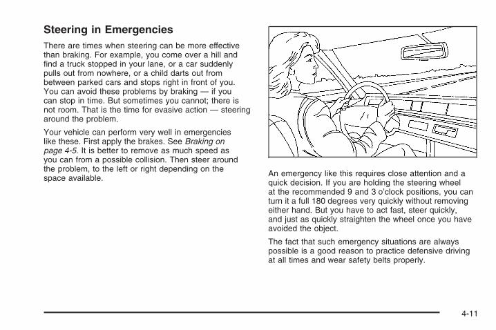
Steering in EmergenciesThere are times when steering can be more effectivethan braking. For example, you come over a hill andfind a truck stopped in your lane, or a car suddenlypulls out from nowhere, or a child darts out frombetween parked cars and stops right in front of you.You can avoid these problems by braking — if youcan stop in time. But sometimes you cannot; there isnot room. That is the time for evasive action — steeringaround the problem.
Your vehicle can perform very well in emergencieslike these. First apply the brakes. See Braking onpage 4-5. It is better to remove as much speed asyou can from a possible collision. Then steer aroundthe problem, to the left or right depending on thespace available. An emergency like this requires close attention and a
quick decision. If you are holding the steering wheelat the recommended 9 and 3 o’clock positions, you canturn it a full 180 degrees very quickly without removingeither hand. But you have to act fast, steer quickly,and just as quickly straighten the wheel once you haveavoided the object.
The fact that such emergency situations are alwayspossible is a good reason to practice defensive drivingat all times and wear safety belts properly.
4-11
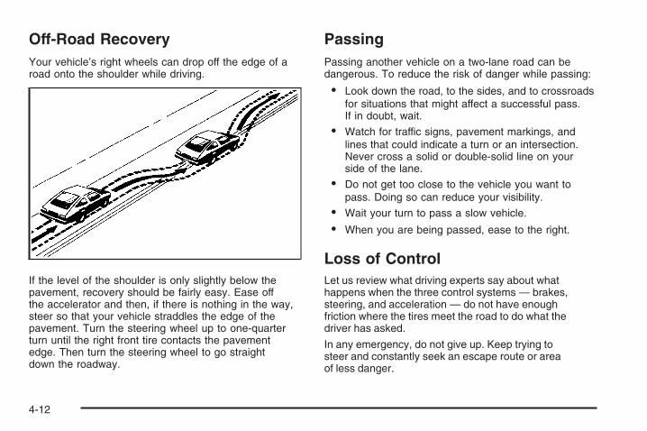
Off-Road RecoveryYour vehicle’s right wheels can drop off the edge of aroad onto the shoulder while driving.
If the level of the shoulder is only slightly below thepavement, recovery should be fairly easy. Ease offthe accelerator and then, if there is nothing in the way,steer so that your vehicle straddles the edge of thepavement. Turn the steering wheel up to one-quarterturn until the right front tire contacts the pavementedge. Then turn the steering wheel to go straightdown the roadway.
PassingPassing another vehicle on a two-lane road can bedangerous. To reduce the risk of danger while passing:
• Look down the road, to the sides, and to crossroadsfor situations that might affect a successful pass.If in doubt, wait.
• Watch for traffic signs, pavement markings, andlines that could indicate a turn or an intersection.Never cross a solid or double-solid line on yourside of the lane.
• Do not get too close to the vehicle you want topass. Doing so can reduce your visibility.
• Wait your turn to pass a slow vehicle.
• When you are being passed, ease to the right.
Loss of ControlLet us review what driving experts say about whathappens when the three control systems — brakes,steering, and acceleration — do not have enoughfriction where the tires meet the road to do what thedriver has asked.
In any emergency, do not give up. Keep trying tosteer and constantly seek an escape route or areaof less danger.
4-12

SkiddingIn a skid, a driver can lose control of the vehicle.Defensive drivers avoid most skids by taking reasonablecare suited to existing conditions, and by not overdrivingthose conditions. But skids are always possible.
The three types of skids correspond to your vehicle’sthree control systems. In the braking skid, the wheelsare not rolling. In the steering or cornering skid,too much speed or steering in a curve causes tires toslip and lose cornering force. And in the accelerationskid, too much throttle causes the driving wheels to spin.
A cornering skid is best handled by easing your footoff the accelerator pedal.
Remember: Any traction control system helps avoidonly the acceleration skid. If your traction controlsystem is off, then an acceleration skid is also besthandled by easing your foot off the accelerator pedal.
If your vehicle starts to slide, ease your foot off theaccelerator pedal and quickly steer the way you wantthe vehicle to go. If you start steering quickly enough,your vehicle may straighten out. Always be readyfor a second skid if it occurs.
Of course, traction is reduced when water, snow, ice,gravel, or other material is on the road. For safety,you will want to slow down and adjust your driving tothese conditions. It is important to slow down on slipperysurfaces because stopping distance will be longerand vehicle control more limited.
While driving on a surface with reduced traction,try your best to avoid sudden steering, acceleration,or braking, including reducing vehicle speed byshifting to a lower gear. Any sudden changes couldcause the tires to slide. You may not realize thesurface is slippery until your vehicle is skidding.Learn to recognize warning clues — such as enoughwater, ice, or packed snow on the road to makea mirrored surface — and slow down when youhave any doubt.
Remember: Any Antilock Brake System (ABS)helps avoid only the braking skid.
4-13

Driving at NightNight driving is more dangerous than day drivingbecause some drivers are likely to be impaired — byalcohol or drugs, with night vision problems, or byfatigue.
Night driving tips include:
• Drive defensively.
• Do not drink and drive.
• Reduce headlamp glare by adjusting theinside rearview mirror.
• Slow down and keep more space betweenyou and other vehicles because headlampscan only light up so much road ahead.
• Watch for animals.
• When tired, pull off the road.
• Do not wear sunglasses.
• Avoid staring directly into approaching headlamps.
• Keep the windshield and all glass on your vehicleclean — inside and out.
• Keep your eyes moving, especially during turnsor curves.
No one can see as well at night as in the daytime.But, as we get older, these differences increase.A 50-year-old driver might need at least twice as muchlight to see the same thing at night as a 20-year-old.
Driving in Rain and on Wet RoadsRain and wet roads can reduce vehicle tractionand affect your ability to stop and accelerate. Alwaysdrive slower in these types of driving conditionsand avoid driving through large puddles anddeep-standing or flowing water.
4-14

{CAUTION:
Wet brakes can cause crashes. They mightnot work as well in a quick stop and couldcause pulling to one side. You could losecontrol of the vehicle.
After driving through a large puddle ofwater or a car/vehicle wash, lightly apply thebrake pedal until the brakes work normally.
Flowing or rushing water creates strongforces. Driving through flowing water couldcause your vehicle to be carried away. If thishappens, you and other vehicle occupantscould drown. Do not ignore police warningsand be very cautious about trying to drivethrough flowing water.
HydroplaningHydroplaning is dangerous. Water can build upunder your vehicle’s tires so they actually ride on thewater. This can happen if the road is wet enoughand you are going fast enough. When your vehicle ishydroplaning, it has little or no contact with the road.
There is no hard and fast rule about hydroplaning.The best advice is to slow down when the road is wet.
Other Rainy Weather TipsBesides slowing down, other wet weather driving tipsinclude:
• Allow extra following distance.
• Pass with caution.
• Keep windshield wiping equipment in good shape.
• Keep the windshield washer fluid reservoir filled.
• Have good tires with proper tread depth.See Tires on page 5-47.
4-15

Before Leaving on a Long TripTo prepare your vehicle for a long trip, consider havingit serviced by your dealer/retailer before departing.
Things to check on your own include:
• Windshield Washer Fluid: Reservoir full?Windows clean — inside and outside?
• Wiper Blades: In good shape?
• Fuel, Engine Oil, Other Fluids: All levels checked?
• Lamps: Do they all work and are lenses clean?
• Tires: Are treads good? Are tires inflatedto recommended pressure?
• Weather and Maps: Safe to travel?Have up-to-date maps?
Highway HypnosisAlways be alert and pay attention to your surroundingswhile driving. If you become tired or sleepy, finda safe place to park your vehicle and rest.
Other driving tips include:
• Keep the vehicle well ventilated.
• Keep interior temperature cool.
• Keep your eyes moving — scan the road aheadand to the sides.
• Check the rearview mirror and vehicleinstruments often.
Hill and Mountain RoadsDriving on steep hills or through mountains is differentthan driving on flat or rolling terrain. Tips for drivingin these conditions include:
• Keep your vehicle serviced and in good shape.
• Check all fluid levels and brakes, tires, coolingsystem, and transmission.
• Going down steep or long hills, shift to a lower gear.
{CAUTION:
If you do not shift down, the brakes could getso hot that they would not work well. Youwould then have poor braking or even nonegoing down a hill. You could crash. Shift downto let the engine assist the brakes on a steepdownhill slope.
4-16
{CAUTION:
Coasting downhill in NEUTRAL (N) or with theignition off is dangerous. The brakes will haveto do all the work of slowing down and theycould get so hot that they would not work well.You would then have poor braking or evennone going down a hill. You could crash.Always have the engine running and yourvehicle in gear when you go downhill.
• Stay in your own lane. Do not swing wide or cutacross the center of the road. Drive at speedsthat let you stay in your own lane.
• Top of hills: Be alert — something could be inyour lane (stalled car, accident).
• Pay attention to special road signs (falling rocksarea, winding roads, long grades, passing orno-passing zones) and take appropriate action.
Winter DrivingHere are some tips for winter driving:
• Have your vehicle in good shape for winter.
• You might want to put winter emergency suppliesin your vehicle.
Include an ice scraper, a small brush or broom, a supplyof windshield washer fluid, a rag, some winter outerclothing, a small shovel, a flashlight, a red cloth, andreflective warning triangles. And, if you will be drivingunder severe conditions, include a small bag of sand,a piece of old carpet, or a couple of burlap bags tohelp provide traction. Be sure you properly securethese items in your vehicle.
Also see Tires on page 5-47.
4-17

Driving on Snow or IceMost of the time, those places where the tires meetthe road probably have good traction.
However, if there is snow or ice between the tiresand the road, you can have a very slippery situation.You have a lot less traction, or grip, and need tobe very careful.
What is the worst time for this? Wet ice. Very cold snowor ice can be slick and hard to drive on. But wet icecan be even more trouble because it can offer the leasttraction of all. You can get wet ice when it is aboutfreezing, 32°F (0°C), and freezing rain begins to fall.Try to avoid driving on wet ice until salt and sand crewscan get there.
Whatever the condition — smooth ice, packed, blowing,or loose snow — drive with caution.
Accelerate gently. Try not to break the fragile traction.If you accelerate too fast, the drive wheels will spin andpolish the surface under the tires even more.
4-18

The Antilock Brake System (ABS) improves yourvehicle’s stability when you make a hard stop on aslippery road. Even though you have ABS, beginstopping sooner than you would on dry pavement.See Antilock Brake System (ABS) on page 4-6.
• Allow greater following distance on anyslippery road.
• Watch for slippery spots. The road might befine until you hit a spot that is covered with ice.On an otherwise clear road, ice patches can appearin shaded areas where the sun cannot reach,such as around clumps of trees, behind buildings,or under bridges. Sometimes the surface of acurve or an overpass can remain icy when thesurrounding roads are clear. If you see a patchof ice ahead of you, brake before you are on it.Try not to brake while you are actually on the ice,and avoid sudden steering maneuvers.
If You Are Caught in a BlizzardIf you are stopped by heavy snow, you could be ina serious situation. You should probably stay with yourvehicle unless you know for sure that you are nearhelp and you can hike through the snow. Here are somethings to do to summon help and keep yourself andyour passengers safe:
• Turn on the hazard warning flashers.
• Tie a red cloth to your vehicle to alert police thatyou have been stopped by the snow.
• Put on extra clothing or wrap a blanket around you.If you do not have blankets or extra clothing, makebody insulators from newspapers, burlap bags,rags, floor mats — anything you can wrap aroundyourself or tuck under your clothing to keep warm.
4-19

You can run the engine to keep warm, but be careful.
{CAUTION:
Snow can trap exhaust gases under yourvehicle. This can cause deadly CO (carbonmonoxide) gas to get inside. CO couldovercome you and kill you. You cannot seeit or smell it, so you might not know it is inyour vehicle. Clear away snow from aroundthe base of your vehicle, especially anythat is blocking the exhaust pipe. And checkaround again from time to time to be suresnow does not collect there.
Open a window just a little on the side of thevehicle that is away from the wind. This willhelp keep CO out.
4-20

Run your engine only as long as you must. Thissaves fuel. When you run the engine, make it goa little faster than just idle. That is, push the acceleratorslightly. This uses less fuel for the heat that youget and it keeps the battery charged. You will needa well-charged battery to restart the vehicle, andpossibly for signaling later on with the headlamps.Let the heater run for a while.
Then, shut the engine off and close the windowalmost all the way to preserve the heat. Start theengine again and repeat this only when you feelreally uncomfortable from the cold. But do it as littleas possible. Preserve the fuel as long as you can.To help keep warm, you can get out of the vehicleand do some fairly vigorous exercises every halfhour or so until help comes.
If Your Vehicle is Stuck in Sand,Mud, Ice, or SnowSlowly and cautiously spin the wheels to free yourvehicle when stuck in sand, mud, ice, or snow. SeeRocking Your Vehicle to Get It Out on page 4-22.
If your vehicle has a traction system, it can often helpto free a stuck vehicle. Refer to your vehicle’s tractionsystem in the Index. If the stuck condition is too severefor the traction system to free the vehicle, turn thetraction system off and use the rocking method.
{CAUTION:
If you let your vehicle’s tires spin at highspeed, they can explode, and you or otherscould be injured. The vehicle can overheat,causing an engine compartment fire or otherdamage. Spin the wheels as little as possibleand avoid going above 35 mph (55 km/h) asshown on the speedometer.
For information about using tire chains on your vehicle,see Tire Chains on page 5-66.
4-21

Rocking Your Vehicle to Get It OutFirst, turn the steering wheel left and right to clearthe area around the front wheels. Turn the tractioncontrol system off. See Traction Control System (TCS)on page 4-7. Then shift back and forth betweenREVERSE (R) and a forward gear, spinning the wheelsas little as possible. To prevent transmission wear,wait until the wheels stop spinning before shiftinggears. Release the accelerator pedal while you shift,and press lightly on the accelerator pedal whenthe transmission is in gear. By slowly spinning thewheels in the forward and reverse directions, you willcause a rocking motion that could free your vehicle.If that does not get your vehicle out after a few tries,it might need to be towed out. If your vehicle doesneed to be towed out, see Towing Your Vehicleon page 4-28.
Loading Your VehicleIt is very important to know how much weight yourvehicle can carry. This weight is called the vehiclecapacity weight and includes the weight of alloccupants, cargo, and all nonfactory-installedoptions. Two labels on your vehicle show how muchweight it may properly carry, the Tire and LoadingInformation label and the Certification/Tire label.
{CAUTION:
Do not load the vehicle any heavier thanthe Gross Vehicle Weight Rating (GVWR),or either the maximum front or rearGross Axle Weight Rating (GAWR). If youdo, parts on the vehicle can break, and itcan change the way your vehicle handles.These could cause you to lose controland crash. Also, overloading can shortenthe life of the vehicle.
4-22

Tire and Loading Information Label
A vehicle specific Tire and Loading Informationlabel is attached to the center pillar (B-pillar).With the driver’s door open, you will find thelabel attached below the door lock post (striker).
The tire and loading information label shows thenumber of occupant seating positions (A), and themaximum vehicle capacity weight (B) in kilogramsand pounds.
The Tire and Loading Information label also showsthe size of the original equipment tires (C) andthe recommended cold tire inflation pressures (D).For more information on tires and inflation seeTires on page 5-47 and Inflation - Tire Pressureon page 5-52.
There is also important loading information onthe vehicle Certification/Tire label. It tells youthe Gross Vehicle Weight Rating (GVWR) andthe Gross Axle Weight Rating (GAWR) for thefront and rear axle. See “Certification/Tire Label”later in this section.
Example Label
4-23

Steps for Determining Correct Load Limit1. Locate the statement “The combined weight
of occupants and cargo should never exceedXXX lbs” on your vehicle’s placard.
2. Determine the combined weight of the driverand passengers that will be riding in yourvehicle.
3. Subtract the combined weight of the driverand passengers from XXX kg or XXX lbs.
4. The resulting figure equals the availableamount of cargo and luggage loadcapacity. For example, if the “XXX” amountequals 1400 lbs and there will be five150 lb passengers in your vehicle, the amountof available cargo and luggage load capacityis 650 lbs (1400 − 750 (5 x 150) = 650 lbs).
5. Determine the combined weight of luggage andcargo being loaded on the vehicle. That weightmay not safely exceed the available cargo andluggage load capacity calculated in Step 4.
6. If your vehicle will be towing a trailer, the loadfrom your trailer will be transferred to yourvehicle. Consult this manual to determine howthis reduces the available cargo and luggageload capacity of your vehicle.
See Towing a Trailer on page 4-31 for importantinformation on towing a trailer, towing safety rulesand trailering tips.
Item Description Total
AVehicle CapacityWeight forExample 1 =
1,000 lbs (453 kg)
BSubtractOccupant Weight150 lbs (68 kg) × 2 =
300 lbs (136 kg)
C Available Occupantand Cargo Weight = 700 lbs (317 kg)
Example 1
4-24

Item Description Total
AVehicle CapacityWeight forExample 2 =
1,000 lbs (453 kg)
BSubtractOccupant Weight150 lbs (68 kg) × 5 =
750 lbs (340 kg)
C Available Occupantand Cargo Weight = 250 lbs (113 kg)
Item Description Total
AVehicle CapacityWeight forExample 3 =
1,000 lbs (453 kg)
BSubtractOccupant Weight200 lbs (91 kg) × 5 =
1,000 lbs (453 kg)
C Available Occupantand Cargo Weight = 0 lbs (0 kg)
Refer to your vehicle’s tire and loadinginformation label for specific information aboutyour vehicle’s capacity weight and seatingpositions. The combined weight of the driver,passengers and cargo should never exceedyour vehicle’s maximum vehicle capacity weight.
Example 2 Example 3
4-25

Certification/Tire Label
A vehicle specific Certification/Tire label isattached to the lower area of the center pillar(B-pillar). The label shows the gross weightcapacity of your vehicle. This is called theGross Vehicle Weight Rating (GVWR).
The GVWR includes the weight of the vehicle,all occupants, fuel, cargo, and trailer tongueweight, if your vehicle is pulling a trailer.
The Certification/Tire label also tells you themaximum weights for the front and rear axles,called Gross Axle Weight Rating (GAWR).To find out the actual loads on your front andrear axles, you need to go to a weigh stationand weigh your vehicle. Your dealer/retailer canhelp you with this. Be sure to spread out yourload equally on both sides of the centerline.
Never exceed the GVWR for your vehicle,or the GAWR for either the front or rear axle.
Similar looking vehicles may have differentGVWRs and payloads. Please consult yourvehicle’s Certification/Tire label or your retailerfor additional details.
4-26

{CAUTION:
Do not load the vehicle any heavier thanthe Gross Vehicle Weight Rating (GVWR),or either the maximum front or rearGross Axle Weight Rating (GAWR). If youdo, parts on the vehicle can break, and itcan change the way your vehicle handles.These could cause you to lose controland crash. Also, overloading can shortenthe life of the vehicle.
Using heavier suspension components to getadded durability might not change your vehicle’sweight ratings. Ask your dealer/retailer to helpyou load your vehicle correctly if you are usingthese components.
Notice: Overloading your vehicle may causedamage. Repairs would not be covered byyour warranty. Do not overload your vehicle.If you put things inside your vehicle — likesuitcases, tools, packages, or anything else — theywill go as fast as the vehicle goes. If you have tostop or turn quickly, or if there is a crash, they willkeep going.
{CAUTION:
Things you put inside your vehicle canstrike and injure people in a sudden stopor turn, or in a crash.
• Put things in the cargo area of yourvehicle. Try to spread the weightevenly.
• Never stack heavier things, likesuitcases, inside the vehicle so thatsome of them are above the tops ofthe seats.
• Do not leave an unsecured childrestraint in your vehicle.
• When you carry something inside thevehicle, secure it whenever you can.
• Do not leave a seat folded downunless you need to.
4-27

Towing
Towing Your VehicleTo avoid vehicle damage, a platform or flatbed trailershould be used to transport this vehicle. Consultyour dealer/retailer or a professional towing serviceif you need to have your disabled vehicle towed.See Roadside Assistance Program on page 7-6.
If you want to tow your vehicle behind another vehiclefor recreational purposes (such as behind a motorhome),see “Recreational Vehicle Towing” following.
Recreational Vehicle TowingRecreational vehicle towing means towing your vehiclebehind another vehicle – such as behind a motorhome.The two most common types of recreational vehicletowing are known as “dinghy towing” (towing your vehiclewith all four wheels on the ground) and “dolly towing”(towing your vehicle with two wheels on the groundand two wheels up on a device known as a “dolly”).
With the proper preparation and equipment, manyvehicles can be towed in these ways. See “DinghyTowing” and “Dolly Towing” following in this section.
Here are some important things to consider beforeyou do recreational vehicle towing:• What’s the towing capacity of the towing vehicle?
Be sure you read the tow vehicle manufacturer’srecommendations.
• How far will you tow? Some vehicles haverestrictions on how far and how long they can tow.
• Do you have the proper towing equipment?See your dealer/retailer or trailering professional foradditional advice and equipment recommendations.
• Is your vehicle ready to be towed? Just as youwould prepare your vehicle for a long trip, you’llwant to make sure your vehicle is prepared tobe towed. See Before Leaving on a Long Tripon page 4-16.
Dinghy TowingFront-wheel-drive vehicles equipped with a manual orautomatic transmission may be dinghy towed fromthe front. These vehicles may also be towed by puttingthe front wheels on a dolly. See “Dolly Towing” laterin this section.
For vehicles being dinghy towed, the vehicle shouldbe run at the beginning of each day and at each RVfuel stop for about five minutes. This will ensure properlubrication of transmission components.
4-28

To tow your vehicle from the front with all four wheelson the ground:1. Position and attach the vehicle to tow it behind
the recreational vehicle.2. Turn the ignition key to ACC/ACCESSORY.3. Shift the transmission to NEUTRAL (N).4. Turn fog lamps and all accessories off.5. Remove the IGN SW fuse from the instrument
panel fuse block. See Instrument Panel FuseBlock on page 5-90 for more information.
Notice: If you tow your vehicle without performingeach of the steps listed under “Dinghy Towing,”you could damage the automatic transmission.Be sure to follow all steps of the dinghy towingprocedure prior to and after towing your vehicle.Notice: If your vehicle has a four-speed automatictransmission, it can be dinghy towed from thefront for unlimited miles at 65 mph (105 km/h).If you exceed 65 mph (105 km/h) while towing yourvehicle, it could be damaged. The repairs wouldnot be covered by your warranty. Never exceed65 mph (105 km/h) while towing your vehicle.
Once you have reached your destination:1. Set the parking brake.2. Shift the transmission to PARK (P).3. Reinstall the IGN SW fuse into the instrument panel
fuse block.4. Turn the ignition key to LOCK/OFF and remove
the key from the ignition.Notice: Too much or too little fluid can damagethe transmission. Be sure that the transmissionfluid is at the proper level before towing with allfour wheels on the ground.Notice: Don’t tow a vehicle with the front drivewheels on the ground if one of the front tires isa compact spare tire. Towing with two different tiresizes on the front of the vehicle can cause severedamage to the transmission.
4-29

Dolly Towing (Front-Wheel-DriveVehicles)
To tow your front-wheel-drive vehicle from the front withtwo wheels on the ground, do the following:
1. Put the front wheels on a dolly.
2. Move the shift lever to PARK (P).
3. Set the parking brake and then remove the key.
4. Clamp the steering wheel in a straight-aheadposition with a clamping device designed for towing.
5. Release the parking brake.
Towing Your Vehicle From the Rear
Notice: Towing your vehicle from the rear coulddamage it. Also, repairs would not be coveredby the warranty. Never have your vehicle towedfrom the rear.
4-30
Towing a Trailer
{CAUTION:
If you do not use the correct equipment anddrive properly, you can lose control when youpull a trailer. For example, if the trailer is tooheavy, the brakes may not work well — oreven at all. You and your passengers couldbe seriously injured. You may also damageyour vehicle; the resulting repairs would notbe covered by your warranty. Pull a traileronly if you have followed all the steps in thissection. Ask your dealer/retailer for adviceand information about towing a trailer withyour vehicle.
Notice: Pulling a trailer improperly can damageyour vehicle and result in costly repairs not coveredby your warranty. To pull a trailer correctly, followthe advice in this part and see your dealer/retailerfor important information about towing a trailerwith your vehicle.
Your vehicle can tow a trailer if it is equipped with theproper trailer towing equipment. To identify the traileringcapacity of your vehicle, you should read the informationin “Weight of the Trailer” that appears later in thissection. Trailering is different than just driving yourvehicle by itself. Trailering means changes in handling,acceleration, braking, durability and fuel economy.Successful, safe trailering takes correct equipment,and it has to be used properly.
That is the reason for this part. In it are manytime-tested, important trailering tips and safety rules.Many of these are important for your safety and thatof your passengers. So please read this sectioncarefully before you pull a trailer.
Load-pulling components such as the engine,transmission, rear axle, wheel assemblies and tires areforced to work harder against the drag of the addedweight. The engine is required to operate at relativelyhigher speeds and under greater loads, generatingextra heat. What’s more, the trailer adds considerablyto wind resistance, increasing the pulling requirements.
4-31

If You Do Decide to Pull a TrailerIf you do, here are some important points:
• There are many different laws, including speedlimit restrictions, having to do with trailering.Make sure your rig will be legal, not only whereyou live but also where you will be driving.A good source for this information can be stateor provincial police.
• Consider using a sway control. See “Hitches”later in this section.
• Do not tow a trailer at all during the first 500 miles(805 km) your new vehicle is driven. Your engine,axle or other parts could be damaged. Therepairs would not be covered by your warranty.
• Then, during the first 500 miles (805 km) that youtow a trailer, do not drive over 50 mph (80 km/h)and do not make starts at full throttle. Thishelps your engine and other parts of yourvehicle wear in at the heavier loads.
• You may want to shift the transmission to a lowergear selection if the transmission shifts too often(e.g., under heavy loads and/or hilly conditions).Using a lower gear will minimize heat buildupand extend the life of your transmission.
• Obey speed limit restrictions when towing a trailer.Do not drive faster than the maximum posted speedfor trailers, or no more than 55 mph (90 km/h),to save wear on your vehicle’s parts.
• Do not tow a trailer when the outside temperatureis above 100°F (38°C).
Three important considerations have to do with weight:
• the weight of the trailer
• the weight of the trailer tongue
• and the total weight on your vehicle’s tires
4-32

Weight of the TrailerHow heavy can a trailer safely be?
It should never weigh more than 1,500 lbs (680 kg).But even that can be too heavy.
It depends on how you plan to use your rig. Forexample, speed, altitude, road grades, outsidetemperature and how much your vehicle is used topull a trailer are all important. It can also depend onany special equipment that you have on your vehicle,and the amount of tongue weight the vehicle cancarry. See “Weight of the Trailer Tongue” later inthis section for more information.
Maximum trailer weight is calculated assuming only thedriver is in the tow vehicle and it has all the requiredtrailering equipment. The weight of additional optionalequipment, passengers and cargo must be subtractedfrom the maximum trailer weight.
You can ask your dealer/retailer for traileringinformation or advice.
Weight of the Trailer TongueThe tongue load (A) of any trailer is an important weightto measure because it affects the total or gross weightof your vehicle. The Gross Vehicle Weight (GVW)includes the curb weight of the vehicle, any cargo youmay carry in it, and the people who will be riding inthe vehicle. If you have a lot of options, equipment,passengers or cargo in your vehicle, it will reducethe tongue weight your vehicle can carry, which willalso reduce the trailer weight your vehicle can tow.And if you tow a trailer, you must add the tongue loadto the GVW because your vehicle will be carryingthat weight, too. See Loading Your Vehicle on page 4-22for more information about your vehicle’s maximumload capacity.
4-33
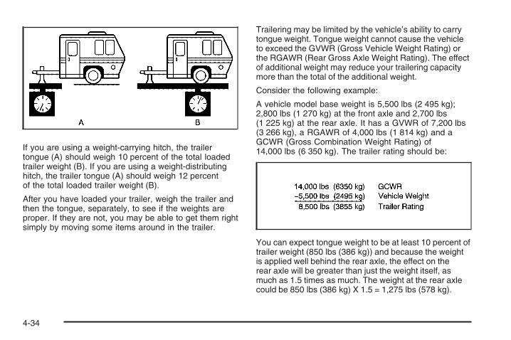
If you are using a weight-carrying hitch, the trailertongue (A) should weigh 10 percent of the total loadedtrailer weight (B). If you are using a weight-distributinghitch, the trailer tongue (A) should weigh 12 percentof the total loaded trailer weight (B).
After you have loaded your trailer, weigh the trailer andthen the tongue, separately, to see if the weights areproper. If they are not, you may be able to get them rightsimply by moving some items around in the trailer.
Trailering may be limited by the vehicle’s ability to carrytongue weight. Tongue weight cannot cause the vehicleto exceed the GVWR (Gross Vehicle Weight Rating) orthe RGAWR (Rear Gross Axle Weight Rating). The effectof additional weight may reduce your trailering capacitymore than the total of the additional weight.
Consider the following example:
A vehicle model base weight is 5,500 lbs (2 495 kg);2,800 lbs (1 270 kg) at the front axle and 2,700 lbs(1 225 kg) at the rear axle. It has a GVWR of 7,200 lbs(3 266 kg), a RGAWR of 4,000 lbs (1 814 kg) and aGCWR (Gross Combination Weight Rating) of14,000 lbs (6 350 kg). The trailer rating should be:
You can expect tongue weight to be at least 10 percent oftrailer weight (850 lbs (386 kg)) and because the weightis applied well behind the rear axle, the effect on therear axle will be greater than just the weight itself, asmuch as 1.5 times as much. The weight at the rear axlecould be 850 lbs (386 kg) X 1.5 = 1,275 lbs (578 kg).
4-34
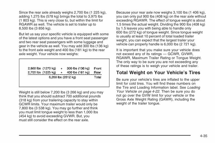
Since the rear axle already weighs 2,700 lbs (1 225 kg),adding 1,275 lbs (578 kg) brings the total to 3,975 lbs(1 803 kg). This is very close to, but within the limit forRGAWR as well. The vehicle is set to trailer up to8,500 lbs (3 856 kg).
But let us say your specific vehicle is equipped with someof the latest options and you have a front seat passengerand two rear seat passengers with some luggage andgear in the vehicle as well. You may add 300 lbs (136 kg)to the front axle weight and 400 lbs (181 kg) to the rearaxle weight. Your vehicle now weighs:
Weight is still below 7,200 lbs (3 266 kg) and you maythink that you should subtract 700 additional pounds(318 kg) from your trailering capacity to stay withinGCWR limits. Your maximum trailer would only be7,800 lbs (3 538 kg). You may go further and thinkyou must limit tongue weight to less than 1,000 lbs(454 kg) to avoid exceeding GVWR. But, youmust still consider the effect on the rear axle.
Because your rear axle now weighs 3,100 lbs (1 406 kg),you can only put 900 lbs (408 kg) on the rear axle withoutexceeding RGAWR. The effect of tongue weight is about1.5 times the actual weight. Dividing the 900 lbs (408 kg)by 1.5 leaves you with being able to handle only600 lbs (272 kg) of tongue weight. Since tongue weightis usually at least 10 percent of total loaded trailerweight, you can expect that the largest trailer yourvehicle can properly handle is 6,000 lbs (2 721 kg).
It is important that you make sure your vehicle doesnot exceed any of its ratings — GCWR, GVWR,RGAWR, Maximum Trailer Rating or Tongue Weight.The only way to be sure you are not exceeding anyof these ratings is to weigh your vehicle and trailer.
Total Weight on Your Vehicle’s TiresBe sure your vehicle’s tires are inflated to the upperlimit for cold tires. You will find these numbers onthe Tire and Loading Information label. See LoadingYour Vehicle on page 4-22. Then be sure you donot go over the GVW limit for your vehicle or theGross Axle Weight Rating (GAWR), including theweight of the trailer tongue.
4-35

HitchesIt is important to have the correct hitch equipment.Crosswinds, large trucks going by and rough roadsare a few reasons why you will need the right hitch.Here are some rules to follow:
• The rear bumper on your vehicle is not intendedfor hitches. Do not attach rental hitches or otherbumper-type hitches to it. Use only a frame-mountedhitch that does not attach to the bumper.
• Will you have to make any holes in the body of yourvehicle when you install a trailer hitch? If you do,then be sure to seal the holes later when you removethe hitch. If you do not seal them, deadly carbonmonoxide (CO) from your exhaust can get intoyour vehicle. See Engine Exhaust on page 2-29.Dirt and water can, too.
Safety ChainsYou should always attach chains between your vehicleand your trailer. Cross the safety chains under the tongueof the trailer so that the tongue will not drop to the road ifit becomes separated from the hitch. Instructions aboutsafety chains may be provided by the hitch manufactureror by the trailer manufacturer. Follow the manufacturer’srecommendation for attaching safety chains and do notattach them to the bumper. Always leave just enoughslack so you can turn with your rig. And, never allowsafety chains to drag on the ground.
Trailer BrakesSince your vehicle is equipped with StabiliTrak®, yourtrailer brakes cannot tap into the vehicle’s hydraulicsystem.
Be sure to read and follow the instructions for thetrailer brakes, so you will be able to install, adjust andmaintain them properly.
Driving with a TrailerTowing a trailer requires a certain amount of experience.Before setting out for the open road, you will want toget to know your rig. Acquaint yourself with the feel ofhandling and braking with the added weight of the trailer.And always keep in mind that the vehicle you aredriving is now a good deal longer and not nearly asresponsive as your vehicle is by itself.
Before you start, check all trailer hitch parts andattachments, safety chains, electrical connector, lamps,tires and mirror adjustment. If the trailer has electricbrakes, start your vehicle and trailer moving and thenapply the trailer brake controller by hand to be surethe brakes are working. This lets you check yourelectrical connection at the same time.
During your trip, check occasionally to be sure thatthe load is secure, and that the lamps and any trailerbrakes are still working.
4-36

Following DistanceStay at least twice as far behind the vehicle ahead asyou would when driving your vehicle without a trailer.This can help you avoid situations that requireheavy braking and sudden turns.
PassingYou will need more passing distance up ahead whenyou are towing a trailer. And, because you are agood deal longer when towing a trailer, you will needto go much farther beyond the passed vehiclebefore you can return to your lane.
Backing UpHold the bottom of the steering wheel with one hand.Then, to move the trailer to the left, just move thathand to the left. To move the trailer to the right,move your hand to the right. Always back up slowlyand, if possible, have someone guide you.
Making Turns
Notice: Making very sharp turns while traileringcould cause the trailer to come in contact withthe vehicle. Your vehicle could be damaged.Avoid making very sharp turns while trailering.
When you are turning with a trailer, make wider turnsthan normal. Do this so your trailer will not strikesoft shoulders, curbs, road signs, trees or otherobjects. Avoid jerky or sudden maneuvers.Signal well in advance.
Turn Signals When Towing a TrailerWhen you tow a trailer, your vehicle may need adifferent turn signal flasher and/or extra wiring.See your dealer/retailer if you need information.The arrows on your instrument panel will flashwhenever you signal a turn or lane change. Properlyhooked up, the trailer lamps will also flash, telling otherdrivers you are about to turn, change lanes or stop.
When towing a trailer, the arrows on your instrumentpanel will flash for turns even if the bulbs on thetrailer are burned out. Thus, you may think driversbehind you are seeing your signal when they arenot. It is important to check occasionally to be surethe trailer bulbs are still working.
4-37

Driving on Grades
Notice: Do not tow on steep continuous gradesexceeding 6 miles (9.6 km). Extended, higherthan normal engine and transmission temperaturesmay result and damage your vehicle. Frequentstops are very important to allow the engine andtransmission to cool.
Reduce speed and shift to a lower gear before youstart down a long or steep downgrade. If you do notshift down, you might have to use your brakes so muchthat they would get hot and no longer work well.
On a long uphill grade, shift down and reduceyour speed to around 45 mph (70 km/h) to reducethe possibility of the engine and the transmissionoverheating. If your engine does overheat, seeEngine Overheating on page 5-23.
Parking on Hills
{CAUTION:
You really should not park your vehicle, witha trailer attached, on a hill. If something goeswrong, your rig could start to move. Peoplecan be injured, and both your vehicle and thetrailer can be damaged.
But if you ever have to park your rig on a hill, here’show to do it:
1. Apply your regular brakes, but do not shift intoPARK (P).When parking uphill, turn your wheels away fromthe curb. When parking downhill, turn your wheelsinto the curb.
2. Have someone place chocks behind the trailerwheels.
4-38
3. When the chocks are in place, release the regularbrakes until the chocks absorb the load.
4. Reapply the regular brakes. Then apply yourparking brake and shift into PARK (P).
5. Release the regular brakes.
When You Are Ready to LeaveAfter Parking on a Hill1. Apply your regular brakes and hold the pedal
down while you:
• start your engine,
• shift into a gear, and
• release the parking brake.
2. Let up on the brake pedal.
3. Drive slowly until the trailer is clear of the chocks.
4. Stop and have someone pick up and storethe chocks.
Maintenance When Trailer TowingYour vehicle will need service more often when youare pulling a trailer. See Scheduled Maintenanceon page 6-4 for more information. Things that areespecially important in trailer operation are automatictransmission fluid (do not overfill), engine oil, axlelubricant, drive belt, cooling system and brake system.Each of these is covered in this manual, and theIndex will help you find them quickly. If you are trailering,it is a good idea to review this information before youstart your trip.
Check periodically to see that all hitch nuts and boltsare tight.
Engine Cooling When Trailer TowingYour cooling system may temporarily overheat duringsevere operating conditions. See Engine Overheatingon page 5-23.
4-39

✍ NOTES
4-40

Service ............................................................5-3Accessories and Modifications ..........................5-3California Proposition 65 Warning .....................5-4California Perchlorate Materials Requirements .....5-4Doing Your Own Service Work .........................5-4Adding Equipment to the Outside of
Your Vehicle ..............................................5-5Fuel ................................................................5-5
Gasoline Octane ............................................5-6Gasoline Specifications ....................................5-6California Fuel ...............................................5-6Additives .......................................................5-7Fuels in Foreign Countries ...............................5-7Filling the Tank ..............................................5-8Filling a Portable Fuel Container .....................5-10
Checking Things Under the Hood ....................5-10Hood Release ..............................................5-11Engine Compartment Overview .......................5-12Engine Oil ...................................................5-13Engine Oil Life System ..................................5-16Engine Air Cleaner/Filter ................................5-18Automatic Transmission Fluid .........................5-20Engine Coolant .............................................5-20Coolant Surge Tank Pressure Cap ..................5-23Engine Overheating .......................................5-23Cooling System ............................................5-25
Windshield Washer Fluid ................................5-29Brakes ........................................................5-30Battery ........................................................5-33Jump Starting ...............................................5-34
Headlamp Aiming ...........................................5-39Bulb Replacement ..........................................5-41
Halogen Bulbs ..............................................5-41Headlamps ..................................................5-42Front Turn Signal and Parking Lamps ..............5-43Taillamps, Turn Signal, Stoplamps and
Back-up Lamps .........................................5-44License Plate Lamp ......................................5-45Replacement Bulbs .......................................5-45
Windshield Wiper Blade Replacement ..............5-46Tires ..............................................................5-47
Tire Sidewall Labeling ...................................5-48Tire Terminology and Definitions .....................5-50Inflation - Tire Pressure .................................5-52Tire Pressure Monitor System .........................5-54Tire Pressure Monitor Operation .....................5-55Tire Inspection and Rotation ...........................5-58When It Is Time for New Tires .......................5-59Buying New Tires .........................................5-60Different Size Tires and Wheels ......................5-62Uniform Tire Quality Grading ..........................5-62
Section 5 Service and Appearance Care
5-1

Wheel Alignment and Tire Balance ..................5-64Wheel Replacement ......................................5-64Tire Chains ..................................................5-66If a Tire Goes Flat ........................................5-67Tire Sealant and Compressor Kit ....................5-68
Appearance Care ............................................5-79Interior Cleaning ...........................................5-79Fabric/Carpet ...............................................5-80Instrument Panel, Vinyl, and Other Plastic
Surfaces ..................................................5-81Care of Safety Belts ......................................5-81Weatherstrips ...............................................5-82Washing Your Vehicle ...................................5-82Cleaning Exterior Lamps/Lenses .....................5-82Finish Care ..................................................5-83Windshield and Wiper Blades .........................5-84Aluminum Wheels .........................................5-84Tires ...........................................................5-85
Sheet Metal Damage .....................................5-85Finish Damage .............................................5-85Underbody Maintenance ................................5-86Chemical Paint Spotting .................................5-86Vehicle Care/Appearance Materials ..................5-86
Vehicle Identification ......................................5-87Vehicle Identification Number (VIN) .................5-87Service Parts Identification Label .....................5-88
Electrical System ............................................5-88Intermediate Voltage Devices and Wiring ..........5-88Add-On Electrical Equipment ..........................5-89Windshield Wiper Fuses ................................5-89Power Windows and Other Power Options .......5-89Fuses and Circuit Breakers ............................5-90Instrument Panel Fuse Block ..........................5-90Underhood Fuse Block ..................................5-93
Capacities and Specifications ..........................5-98
Section 5 Service and Appearance Care
5-2

ServiceFor service and parts needs, visit your dealer/retailer.You will receive genuine Saturn parts and Saturn-trainedand supported service people.
Genuine Saturn parts have one of these marks.
Accessories and ModificationsWhen non-dealer/non-retailer accessories are added toyour vehicle they can affect your vehicle’s performanceand safety, including such things as, airbags, braking,stability, ride and handling, emissions systems,aerodynamics, durability, and electronic systems likeantilock brakes, traction control and stability control.Some of these accessories could even causemalfunction or damage not covered by warranty.
GM Accessories are designed to complement andfunction with other systems on your vehicle. Your GMdealer/retailer can accessorize your vehicle usinggenuine GM Accessories. When you go to your GMdealer/retailer and ask for GM Accessories, youwill know that GM-trained and supported servicetechnicians will perform the work using genuineGM Accessories.
Also, see Adding Equipment to Your Airbag-EquippedVehicle on page 1-68.
5-3

California Proposition 65 WarningMost motor vehicles, including this one, contain and/oremit chemicals known to the State of California to causecancer and birth defects or other reproductive harm.Engine exhaust, many parts and systems (includingsome inside the vehicle), many fluids, and somecomponent wear by-products contain and/or emitthese chemicals.
California Perchlorate MaterialsRequirementsCertain types of automotive applications, such as airbaginitiators, seat belt pretensioners, and lithium batteriescontained in remote keyless entry transmitters, maycontain perchlorate materials. Special handling maybe necessary. For additional information, seewww.dtsc.ca.gov/hazardouswaste/perchlorate.
Doing Your Own Service Work
{CAUTION:
Never try to do your own service on hybridcomponents. You can be injured and yourvehicle can be damaged if you try to do yourown service work. Service and repair of thesehybrid components should only be performedby a trained service technician with the properknowledge and tools.
5-4

{CAUTION:
You can be injured and your vehicle could bedamaged if you try to do service work on avehicle without knowing enough about it.
• Be sure you have sufficient knowledge,experience, the proper replacement parts,and tools before you attempt any vehiclemaintenance task.
• Be sure to use the proper nuts, bolts,and other fasteners. English and metricfasteners can be easily confused. If youuse the wrong fasteners, parts can laterbreak or fall off. You could be hurt.
If you want to do some of your own service work, youshould use the proper service manual. It tells you muchmore about how to service your vehicle than this manualcan. To order the proper service manual, see ServicePublications Ordering Information on page 7-14.
Your vehicle has an airbag system. Before attemptingto do your own service work, see Servicing YourAirbag-Equipped Vehicle on page 1-68.
You should keep a record with all parts receipts andlist the mileage and the date of any service workyou perform. See Maintenance Record on page 6-14.
Adding Equipment to the Outsideof Your VehicleThings you might add to the outside of your vehicle canaffect the airflow around it. This can cause wind noiseand can affect fuel economy and windshield washerperformance. Check with your dealer/retailer beforeadding equipment to the outside of your vehicle.
FuelUse of the recommended fuel is an important part of theproper maintenance of your vehicle. To help keep theengine clean and maintain optimum vehicle performance,we recommend the use of gasoline advertised as TOPTIER Detergent Gasoline.
5-5

Gasoline OctaneUse regular unleaded gasoline with a posted octanerating of 87 or higher. If the octane rating is less than 87,you might notice an audible knocking noise when youdrive, commonly referred to as spark knock. If thisoccurs, use a gasoline rated at 87 octane or higheras soon as possible. If you are using gasoline ratedat 87 octane or higher and you hear heavy knocking,the engine needs service.
Gasoline SpecificationsAt a minimum, gasoline should meet ASTM specificationD 4814 in the United States or CAN/CGSB-3.5 or 3.511 inCanada. Some gasolines contain an octane-enhancingadditive called methylcyclopentadienyl manganesetricarbonyl (MMT). We recommend against the use ofgasolines containing MMT. See Additives on page 5-7for additional information.
California FuelIf your vehicle is certified to meet California EmissionsStandards, it is designed to operate on fuels that meetCalifornia specifications. See the underhood emissioncontrol label. If this fuel is not available in states adoptingCalifornia emissions standards, your vehicle will operatesatisfactorily on fuels meeting federal specifications, butemission control system performance might be affected.The malfunction indicator lamp could turn on and yourvehicle might fail a smog-check test. See MalfunctionIndicator Lamp on page 3-36. If this occurs, return to yourauthorized dealer/retailer for diagnosis. If it is determinedthat the condition is caused by the type of fuel used,repairs might not be covered by the vehicle warranty.
5-6

AdditivesTo provide cleaner air, all gasolines in the United Statesare now required to contain additives that help preventengine and fuel system deposits from forming, allowingthe emission control system to work properly. In mostcases, you should not have to add anything to the fuel.However, some gasolines contain only the minimumamount of additive required to meet U.S. EnvironmentalProtection Agency regulations. To help keep fuel injectorsand intake valves clean, or if your vehicle experiencesproblems due to dirty injectors or valves, look for gasolinethat is advertised as TOP TIER Detergent Gasoline. Also,your dealer/retailer has additives that will help correct andprevent most deposit-related problems.
Gasolines containing oxygenates, such as ethers andethanol, and reformulated gasolines might be available inyour area. We recommend that you use these gasolines,if they comply with the specifications described earlier.However, E85 (85% ethanol) and other fuels containingmore than 10% ethanol must not be used in vehicles thatwere not designed for those fuels.
Notice: Your vehicle was not designed for fuel thatcontains methanol. Do not use fuel containingmethanol. It can corrode metal parts in the fuelsystem and also damage plastic and rubber parts.That damage would not be covered under yourwarranty.
Some gasolines that are not reformulated forlow emissions can contain an octane-enhancingadditive called methylcyclopentadienyl manganesetricarbonyl (MMT); ask the attendant where you buygasoline whether the fuel contains MMT. We recommendagainst the use of such gasolines. Fuels containing MMTcan reduce the life of spark plugs and the performanceof the emission control system could be affected. Themalfunction indicator lamp might turn on. If this occurs,return to your dealer/retailer for service.
Fuels in Foreign CountriesIf you plan on driving in another country outside theUnited States or Canada, the proper fuel might be hardto find. Never use leaded gasoline or any other fuelnot recommended in the previous text on fuel. Costlyrepairs caused by use of improper fuel would notbe covered by your warranty.
To check the fuel availability, ask an auto club, orcontact a major oil company that does business inthe country where you will be driving.
5-7
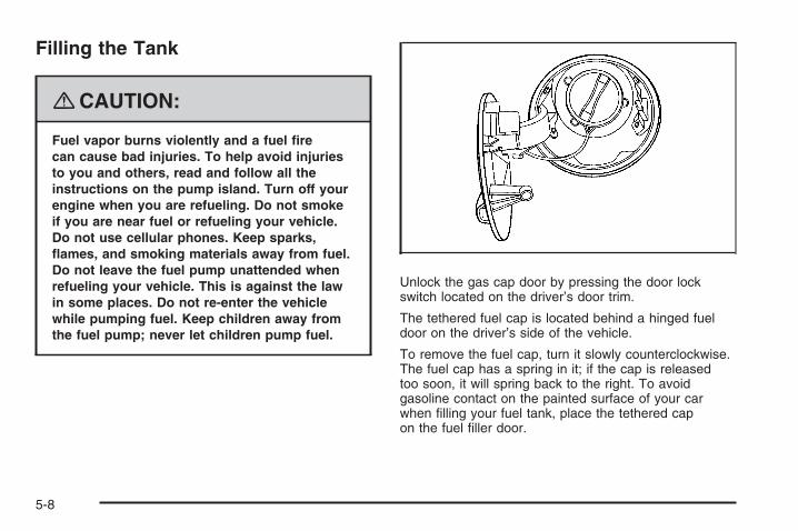
Filling the Tank
{CAUTION:
Fuel vapor burns violently and a fuel firecan cause bad injuries. To help avoid injuriesto you and others, read and follow all theinstructions on the pump island. Turn off yourengine when you are refueling. Do not smokeif you are near fuel or refueling your vehicle.Do not use cellular phones. Keep sparks,flames, and smoking materials away from fuel.Do not leave the fuel pump unattended whenrefueling your vehicle. This is against the lawin some places. Do not re-enter the vehiclewhile pumping fuel. Keep children away fromthe fuel pump; never let children pump fuel.
Unlock the gas cap door by pressing the door lockswitch located on the driver’s door trim.
The tethered fuel cap is located behind a hinged fueldoor on the driver’s side of the vehicle.
To remove the fuel cap, turn it slowly counterclockwise.The fuel cap has a spring in it; if the cap is releasedtoo soon, it will spring back to the right. To avoidgasoline contact on the painted surface of your carwhen filling your fuel tank, place the tethered capon the fuel filler door.
5-8

{CAUTION:
Fuel can spray out on you if you open thefuel cap too quickly. If you spill fuel and thensomething ignites it, you could be badly burned.This spray can happen if your tank is nearly full,and is more likely in hot weather. Open the fuelcap slowly and wait for any hiss noise to stop.Then unscrew the cap all the way.
Be careful not to spill fuel. Do not top off or overfill thetank and wait a few seconds after you have finishedpumping before removing the nozzle. Clean fuel frompainted surfaces as soon as possible. See WashingYour Vehicle on page 5-82.
When replacing the fuel cap, turn it clockwise until itclicks. Make sure the cap is fully installed. The diagnosticsystem can determine if the fuel cap has been left off orimproperly installed. This would allow fuel to evaporateinto the atmosphere. See Malfunction Indicator Lamp onpage 3-36.
{CAUTION:
If a fire starts while you are refueling, do notremove the nozzle. Shut off the flow of fuel byshutting off the pump or by notifying thestation attendant. Leave the area immediately.
Notice: If you need a new fuel cap, be sure to getthe right type. Your dealer/ retailer can get onefor you. If you get the wrong type, it may notfit properly. This may cause your malfunctionindicator lamp to light and may damage your fueltank and emissions system. See MalfunctionIndicator Lamp on page 3-36.
5-9

Filling a Portable Fuel Container
{CAUTION:
Never fill a portable fuel container while itis in your vehicle. Static electricity dischargefrom the container can ignite the fuel vapor.You can be badly burned and your vehicledamaged if this occurs. To help avoid injuryto you and others:
• Dispense fuel only into approvedcontainers.
• Do not fill a container while it is inside avehicle, in a vehicle’s trunk, pickup bed,or on any surface other than the ground.
• Bring the fill nozzle in contact with theinside of the fill opening before operatingthe nozzle. Contact should be maintaineduntil the filling is complete.
• Do not smoke while pumping fuel.• Do not use a cellular phone while
pumping fuel.
Checking Things Underthe Hood
{CAUTION:
An electric fan under the hood can start upand injure you even when the engine is notrunning. Keep hands, clothing, and tools awayfrom any underhood electric fan.
{CAUTION:
Things that burn can get on hot engine partsand start a fire. These include liquids like fuel,oil, coolant, brake fluid, windshield washer andother fluids, and plastic or rubber. You orothers could be burned. Be careful not to dropor spill things that will burn onto a hot engine.
5-10

Hood ReleaseTo open the hood, do the following:
1. Pull the handle withthis symbol on it. It islocated under theinstrument panel onthe driver side ofthe vehicle.
2. Then go to the front of the vehicle and lift up on thesecondary hood release lever.
3. Lift the hood.
Before closing the hood, be sure all the filler caps areon properly. Then pull the hood down and close it firmly.
5-11

Engine Compartment OverviewWhen you open the hood, you will see the following:
5-12
A. Engine Air Cleaner/Filter. Engine Air Cleaner/Filteron page 5-18.
B. Engine Oil Fill Cap. Engine Oil on page 5-13.C. Engine Coolant Surge Tank. Cooling System on
page 5-25.D. Engine Coolant Surge Tank Protection Cap. Coolant
Surge Tank Pressure Cap on page 5-23.E. Main Underhood Fuse Block. Contains Remote
Positive (+) Terminal (Under engine cover).See Jump Starting on page 5-34.
F. Battery. Engine Air Cleaner/Filter on page 5-18.G. Windshield Washer Fluid Reservoir. Windshield
Washer Fluid on page 5-29.H. Engine Oil Dipstick (out of view). Engine Oil on
page 5-13.
Engine Oil
Checking Engine OilIt is a good idea to check the engine oil every time youget fuel. In order to get an accurate reading, the oilmust be warm and the vehicle must be on level ground.
The engine oil dipstick handle is a yellow loop. SeeEngine Compartment Overview on page 5-12 forthe location of the engine oil dipstick.
1. Turn off the engine and give the oil several minutesto drain back into the oil pan. If you do not do this,the oil dipstick might not show the actual level.
2. Pull the dipstick and clean it with a paper towel orcloth, then push it back in all the way. Remove itagain, keeping the tip down and check the level.
5-13

When to Add Engine Oil
If the oil is below the MIN (minimum) mark, add at leastone quart/liter of the recommended oil. This sectionexplains what kind of oil to use. For engine oil crankcasecapacity, see Capacities and Specifications onpage 5-98.
Notice: Do not add too much oil. If the enginehas so much oil that the oil level gets above theupper mark that shows the proper operating range,the engine could be damaged.
See Engine CompartmentOverview on page 5-12for the location of theengine oil fill cap.
Be sure to add enough oil to put the level somewhere inthe proper operating range. Push the dipstick all theway back in when you are through.
5-14

What Kind of Engine Oil to Use
Look for three things:
• GM6094M
Your vehicle’s engine requires oil meeting GMStandard GM6094M. Look for and use only an oilthat meets GM Standard GM6094M.
• SAE 5W-30
As shown in the viscosity chart, SAE 5W-30 is bestfor your vehicle.
These numbers on an oil container show itsviscosity, or thickness. Do not use other viscosityoils such as SAE 20W-50.
• American Petroleum Institute (API) starburst symbol
Oils meeting theserequirements should havethe starburst symbol on thecontainer. This symbolindicates that the oil hasbeen certified by theAmerican PetroleumInstitute (API).
Look for this information on the oil container, anduse only those oils that are identified as meeting GMStandard GM6094M and have the starburst symbol onthe front of the oil container.
Notice: Use only engine oil identified as meetingGM Standard GM6094M and showing the AmericanPetroleum Institute Certified For Gasoline Enginesstarburst symbol. Failure to use the recommendedoil can result in engine damage not covered byyour warranty.
5-15

If you are in an area of extreme cold, wherethe temperature falls below −20°F (−29°C), it isrecommended that you use either an SAE 5W-30synthetic oil or an SAE 0W-30 oil. Both provide easiercold starting and better protection for the engine atextremely low temperatures.
Engine Oil AdditivesDo not add anything to the oil. The recommendedoils with the starburst symbol that meet GM StandardGM6094M are all you need for good performanceand engine protection.
Engine Oil Life System
When to Change Engine OilYour vehicle has a computer system that lets youknow when to change the engine oil and filter. This isbased on engine revolutions and engine temperature,and not on mileage. Based on driving conditions, themileage at which an oil change will be indicated can varyconsiderably. For the oil life system to work properly, youmust reset the system every time the oil is changed.
When the system has calculated that oil life has beendiminished, it will indicate that an oil change is necessary.A change engine oil light will come on. See ChangeEngine Oil Light on page 3-39. Change the oil as soonas possible within the next 600 miles (1 000 km). It ispossible that, if you are driving under the best conditions,the oil life system might not indicate that an oil change isnecessary for over a year. However, the engine oil andfilter must be changed at least once a year and at thistime the system must be reset. Your dealer/retailer hastrained service people who will perform this work usinggenuine parts and reset the system. It is also importantto check the oil regularly and keep it at the proper level.
If the system is ever reset accidentally, you mustchange the oil at 3,000 miles (5 000 km) since yourlast oil change. Remember to reset the oil life systemwhenever the oil is changed.
5-16

How to Reset the Engine Oil LifeSystemThe Engine Oil Life System calculates when to changethe engine oil and filter based on vehicle use. Wheneverthe oil is changed, reset the system so it can calculatewhen the next oil change is required. If a situation occurswhere you change the oil prior to a change engine oil lightbeing turned on, reset the system.
After changing the engine oil, reset the system:
1. Turn the ignition key to ON/RUN with the engine off.
2. Fully press and release the accelerator pedal threetimes within five seconds.If the change engine oil light is not on, the systemis reset.
If the light comes on again and stays on for 30 secondsat the next ignition cycle, it did not reset. You willneed to reset the system again.
What to Do with Used OilUsed engine oil contains certain elements that can beunhealthy for your skin and could even cause cancer.Do not let used oil stay on your skin for very long. Cleanyour skin and nails with soap and water, or a good handcleaner. Wash or properly dispose of clothing or ragscontaining used engine oil. See the manufacturer’swarnings about the use and disposal of oil products.
Used oil can be a threat to the environment. If youchange your own oil, be sure to drain all the oil from thefilter before disposal. Never dispose of oil by putting it inthe trash, pouring it on the ground, into sewers, or intostreams or bodies of water. Instead, recycle it by taking itto a place that collects used oil. If you have a problemproperly disposing of used oil, ask your dealer/retailer,a service station, or a local recycling center for help.
5-17

Engine Air Cleaner/FilterSee Engine Compartment Overview on page 5-12 forthe location of the engine air cleaner/filter.
When to Inspect the Engine AirCleaner/FilterInspect the air cleaner/filter at the Maintenance IIintervals and replace it at the first oil change aftereach 50,000 mile (80 000 km) interval. See ScheduledMaintenance on page 6-4 for more information.If you are driving in dusty/dirty conditions, inspectthe filter at each engine oil change.
How to Inspect the Engine AirCleaner/FilterTo inspect the air cleaner/filter remove the filter fromthe vehicle and lightly shake the filter to releaseloose dust and dirt. If the filter remains caked withdirt, a new filter is required.
To inspect or replace the engine air cleaner/filter, do thefollowing:
1. Unscrew the clamp onthe air duct hose.
2. Disconnect the hose.
3. Unscrew the four bolts on the side of the air cleanerassembly.
4. Turn the cover upward to disengage the coverhinges.
5. Remove the air cleaner cover assembly and airfilter element.
5-18

6. Inspect or replace the air filter element.If the air filter element is dirty, you should replace it.If it is only dusty, it may be cleaned by blowingcompressed air through it from the clean side.Make sure you are away from the enginecompartment when cleaning the air filter withcompressed air.Wipe all dust from inside of the housing and inspectthe air cleaner and air outlet duct for cracks, cutsand deterioration. The air outlet duct must bereplaced if damaged.
7. Reverse Steps 1 through 5 to reinstall the engineair cleaner/filter cover and air duct hose.
{CAUTION:
Operating the engine with the air cleaner/filteroff can cause you or others to be burned.The air cleaner not only cleans the air; it helpsto stop flames if the engine backfires. If it isnot there and the engine backfires, you couldbe burned. Do not drive with it off, and becareful working on the engine with the aircleaner/filter off.
Notice: If the air cleaner/filter is off, a backfire cancause a damaging engine fire. And, dirt can easily getinto your engine, which will damage it. Always havethe air cleaner/filter in place when you are driving.
5-19

Automatic Transmission FluidIt is not necessary to check the transmission fluid level.A transaxle fluid leak is the only reason for fluid loss.If a leak occurs, take the vehicle to your dealer/retailerservice department and have it repaired as soon aspossible.
Change the fluid and filter at the intervals listed inAdditional Required Services on page 6-6, and besure to use the transaxle fluid listed in RecommendedFluids and Lubricants on page 6-12.
Notice: Use of the incorrect automatic transaxlefluid may damage your vehicle, and the damages maynot be covered by your warranty. Always use theautomatic transaxle fluid listed in RecommendedFluids and Lubricants on page 6-12.
Engine CoolantThe cooling system in your vehicle is filled withDEX-COOL® engine coolant. This coolant is designedto remain in your vehicle for five years or 150,000 miles(240 000 km), whichever occurs first, if you add onlyDEX-COOL® extended life coolant.
The following explains your cooling system and how toadd coolant when it is low. If you have a problem withengine overheating, see Engine Overheating onpage 5-23.
A 50/50 mixture of clean, drinkable water andDEX-COOL® coolant will:
• Give freezing protection down to −34°F (−37°C).
• Give boiling protection up to 265°F (129°C).
• Protect against rust and corrosion.
• Help keep the proper engine temperature.
• Let the warning lights and gages work as theyshould.
Notice: Using coolant other than DEX-COOL® maycause premature engine, heater core, or radiatorcorrosion. In addition, the engine coolant mayrequire changing sooner, at the first maintenanceservice after each 30,000 miles (50 000 km) or24 months, whichever occurs first. Any repairswould not be covered by your warranty. Always useDEX-COOL® (silicate-free) coolant in your vehicle.
5-20

What to UseUse a mixture of one-half clean, drinkable water andone-half DEX-COOL® coolant which will not damagealuminum parts. If you use this coolant mixture, you donot need to add anything else.
{CAUTION:
Adding only plain water to the cooling systemcan be dangerous. Plain water, or some otherliquid such as alcohol, can boil before theproper coolant mixture will. The vehicle’scoolant warning system is set for the propercoolant mixture. With plain water or the wrongmixture, the engine could get too hot but youwould not get the overheat warning. The enginecould catch fire and you or others could beburned. Use a 50/50 mixture of clean, drinkablewater and DEX-COOL® coolant.
Notice: If you use an improper coolant mixture,your engine could overheat and be badly damaged.The repair cost would not be covered by yourwarranty. Too much water in the mixture can freezeand crack the engine, radiator, heater core, andother parts.
If you have to add coolant more than four times a year,have your dealer/retailer check your cooling system.
Notice: If you use extra inhibitors and/or additivesin your vehicle’s cooling system, you could damageyour vehicle. Use only the proper mixture of theengine coolant listed in this manual for the coolingsystem. See Recommended Fluids and Lubricantson page 6-12 for more information.
5-21

Checking Coolant
The surge tank is located on the driver side of theengine compartment. See Engine CompartmentOverview on page 5-12 for more information on location.
{CAUTION:
Turning the surge tank pressure cap when theengine and radiator are hot can allow steamand scalding liquids to blow out and burn youbadly. Never turn the surge tank pressurecap — even a little — when the engine andradiator are hot.
The vehicle must be on a level surface. When yourengine is cold, the coolant level should be between theMIN and MAX lines.
Adding CoolantIf you need more coolant, add the proper DEX-COOL®
coolant mixture at the surge tank, but only when theengine is cool. See Engine Overheating on page 5-23for instructions on “How to Add Coolant to the CoolantSurge Tank.”
5-22

{CAUTION:
You can be burned if you spill coolant on hotengine parts. Coolant contains ethylene glycol,and it will burn if the engine parts are hotenough. Do not spill coolant on a hot engine.
When replacing the pressure cap, make sure it ishand-tight and fully seated.
Coolant Surge Tank Pressure CapNotice: If the pressure cap is not tightly installed,coolant loss and possible engine damage mayoccur. Be sure the cap is properly and tightlysecured.
If you need to replace your coolant surge tank pressurecap, see your retailer.
Engine OverheatingThere is a coolant temperature warning light on yourvehicle’s instrument panel. See Engine CoolantTemperature Warning Light on page 3-35.
If Steam Is Coming From Your Engine
{CAUTION:
Steam from an overheated engine can burnyou badly, even if you just open the hood.Stay away from the engine if you see or hearsteam coming from it. Just turn it off and geteveryone away from the vehicle until it coolsdown. Wait until there is no sign of steam orcoolant before you open the hood.
If you keep driving when your engine isoverheated, the liquids in it can catch fire.You or others could be badly burned. Stopyour engine if it overheats, and get out of thevehicle until the engine is cool.
Notice: If your engine catches fire because youkeep driving with no coolant, your vehicle canbe badly damaged. The costly repairs would notbe covered by your warranty.
5-23

If No Steam Is Coming From YourEngineIf you get an engine overheat warning, but see orhear no steam, the problem may not be too serious.Sometimes the engine can get a little too hot when you:
• Climb a long hill on a hot day.
• Stop after high-speed driving.
• Idle for long periods in traffic.
• Tow a trailer.
If you get the overheat warning with no sign of steam,try this for a minute or so:
1. If you have an air conditioner and it is on, turn it off.
2. Turn on your heater to full hot at the highest fanspeed and open the windows as necessary.
3. Try to minimize engine load. If you are in a trafficjam, shift to NEUTRAL (N); otherwise, shift to thehighest gear possible while driving.
If you no longer have the overheat warning, you candrive. Just to be safe, drive slower for about ten minutes.If the warning does not come back on, you can drivenormally.
If the warning continues and you have not stopped, pullover, stop, and park your vehicle right away.
If there is still no sign of steam, idle the engine forthree minutes while you are parked. If the warningcontinues, turn off the engine and get everyone out ofthe vehicle until it cools down.
You may decide not to lift the hood but to get servicehelp right away.
5-24
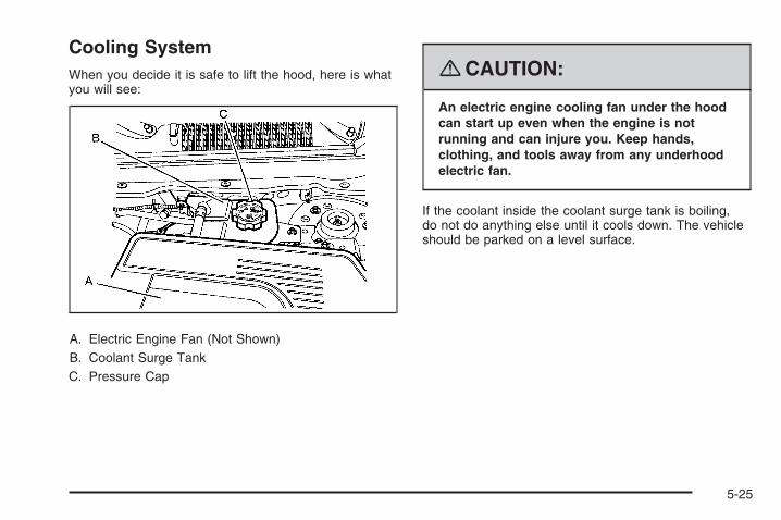
Cooling SystemWhen you decide it is safe to lift the hood, here is whatyou will see:
A. Electric Engine Fan (Not Shown)B. Coolant Surge TankC. Pressure Cap
{CAUTION:
An electric engine cooling fan under the hoodcan start up even when the engine is notrunning and can injure you. Keep hands,clothing, and tools away from any underhoodelectric fan.
If the coolant inside the coolant surge tank is boiling,do not do anything else until it cools down. The vehicleshould be parked on a level surface.
5-25

The coolant level should be between the MIN and MAXlines. If it is not, you may have a leak at the radiatorhoses, heater hoses, radiator, water pump, orsomewhere else in the cooling system.
{CAUTION:
Heater and radiator hoses, and other engineparts, can be very hot. Do not touch them.If you do, you can be burned.
Do not run the engine if there is a leak. If yourun the engine, it could lose all coolant. Thatcould cause an engine fire, and you could beburned. Get any leak fixed before you drive thevehicle.
If there seems to be no leak, with the engine on, checkto see if the electric engine cooling fan is running. If theengine is overheating, the fan should be running. If it isnot, your vehicle needs service. Turn off the engine.
Notice: Engine damage from running the enginewithout coolant is not covered by the warranty.
Notice: Using coolant other than DEX-COOL® maycause premature engine, heater core, or radiatorcorrosion. In addition, the engine coolant couldrequire changing sooner, at 30,000 miles (50 000 km)or 24 months, whichever occurs first. Any repairswould not be covered by the warranty. Alwaysuse DEX-COOL® (silicate-free) coolant in the vehicle.
How to Add Coolant to the CoolantSurge Tank
Notice: This vehicle has a specific coolant fillprocedure. Failure to follow this procedure couldcause your engine to overheat and be severelydamaged.
If you have not found a problem yet, check to see ifcoolant is visible in the surge tank. If coolant is visiblebut the coolant level is not at between the MIN and MAXlines, add a 50/50 mixture of clean, drinkable waterand DEX-COOL® coolant at the coolant surge tank,but be sure the cooling system, including the coolantsurge tank pressure cap, is cool before you do it.See Engine Coolant on page 5-20 for more information.
5-26

{CAUTION:
Steam and scalding liquids from a hot coolingsystem can blow out and burn you badly. Theyare under pressure, and if you turn the coolantsurge tank pressure cap — even a little — theycan come out at high speed. Never turn thecap when the cooling system, including thecoolant surge tank pressure cap, is hot. Waitfor the cooling system and coolant surge tankpressure cap to cool if you ever have to turnthe pressure cap.
{CAUTION:
Adding only plain water to the cooling systemcan be dangerous. Plain water, or some otherliquid such as alcohol, can boil before theproper coolant mixture will. The vehicle’scoolant warning system is set for the propercoolant mixture. With plain water or the wrongmixture, the engine could get too hot but youwould not get the overheat warning. The enginecould catch fire and you or others could beburned. Use a 50/50 mixture of clean, drinkablewater and DEX-COOL® coolant.
Notice: In cold weather, water can freeze and crackthe engine, radiator, heater core and other parts.Use the recommended coolant and the propercoolant mixture.
5-27

{CAUTION:
You can be burned if you spill coolant on hotengine parts. Coolant contains ethylene glycoland it will burn if the engine parts are hotenough. Do not spill coolant on a hot engine.
1. You can remove thecoolant surge tankpressure cap whenthe cooling system,including the coolantsurge tank pressurecap and upper radiatorhose, is no longer hot.
Turn the pressure cap slowly counterclockwiseabout one-quarter of a turn. If you hear a hiss,wait for that to stop. This will allow any pressurestill left to be vented out the discharge hose.
2. Then keep turning the pressure cap slowly, andremove it.
3. Fill the coolant surge tank with the properDEX-COOL® coolant mixture, to between theMIN and MAX lines.
4. With the coolant surge tank pressure cap off, startthe engine and let it run until you can feel the upperradiator hose getting hot. Watch out for the enginecooling fan.By this time, the coolant level inside the coolantsurge tank may be lower. If the level is lower, addmore of the proper DEX-COOL® coolant mixtureto the coolant surge tank until the level reachesbetween the MIN and MAX lines.
5. Then replace the pressure cap. Be sure thepressure cap is hand-tight.
5-28

Check the level in the surge tank when the coolingsystem has cooled down. If the coolant is not at theproper level, repeat Steps 1 through 3 and reinstall thepressure cap. If the coolant still is not at the proper levelwhen the system cools down again, see your retailer.
Windshield Washer Fluid
What to UseWhen you need windshield or rear window washer fluid,be sure to read the manufacturer’s instructions beforeuse. If you will be operating your vehicle in an areawhere the temperature may fall below freezing, use afluid that has sufficient protection against freezing.
Adding Windshield Washer Fluid
Open the cap with thewasher symbol on it.Add washer fluid until thetank is full. See EngineCompartment Overviewon page 5-12 for reservoirlocation.
Notice:
• When using concentrated washer fluid, followthe manufacturer’s instructions for addingwater.
• Do not mix water with ready-to-use washer fluid.Water can cause the solution to freeze anddamage your washer fluid tank and other partsof the washer system. Also, water does notclean as well as washer fluid.
• Fill the washer fluid tank only three-quartersfull when it is very cold. This allows for fluidexpansion if freezing occurs, which coulddamage the tank if it is completely full.
• Do not use engine coolant (antifreeze) in yourwindshield washer. It can damage the vehicle’swindshield washer system and paint.
5-29

Brakes
Brake Fluid
The brake master cylinderreservoir is filled withDOT-3 brake fluid. SeeEngine CompartmentOverview on page 5-12 forthe location of the reservoir.
There are only two reasons why the brake fluid level inthe reservoir might go down. The first is that the brakefluid goes down to an acceptable level during normalbrake lining wear. When new linings are put in, the fluidlevel goes back up. The other reason is that fluid isleaking out of the brake hydraulic system. If it is, havethe brake hydraulic system fixed, since a leak meansthat sooner or later the brakes will not work well.
It is not a good idea to top off the brake fluid. Addingbrake fluid will not correct a leak. If fluid is added whenthe linings are worn, there will be too much fluid whennew brake linings are installed. Add or remove brakefluid, as necessary, only when work is done on the brakehydraulic system.
{CAUTION:
If your vehicle has too much brake fluid, it canspill on the engine. The fluid will burn if theengine is hot enough. You or others could beburned, and your vehicle could be damaged.Add brake fluid only when work is done on thebrake hydraulic system.
When the brake fluid falls to a low level, the brakewarning light comes on. See Brake System WarningLight on page 3-32.
5-30

What to AddWhen you need brake fluid, use only DOT-3 brake fluid.Use new brake fluid from a sealed container only.See Recommended Fluids and Lubricants on page 6-12.
Always clean the brake fluid reservoir cap and thearea around the cap before removing it. This helps keepdirt from entering the reservoir.
{CAUTION:
With the wrong kind of fluid in the brakehydraulic system, the brakes might not workwell. This could cause a crash. Always use theproper brake fluid.
Notice:
• Using the wrong fluid can badly damage brakehydraulic system parts. For example, just afew drops of mineral-based oil, such as engineoil, in the brake hydraulic system can damagebrake hydraulic system parts so badly that theywill have to be replaced. Do not let someoneput in the wrong kind of fluid.
• If you spill brake fluid on your vehicle’s paintedsurfaces, the paint finish can be damaged.Be careful not to spill brake fluid on yourvehicle. If you do, wash it off immediately.See Washing Your Vehicle on page 5-82.
5-31

Brake WearYour vehicle has disc brakes. Disc brake pads havebuilt-in wear indicators that make a high-pitched warningsound when the brake pads are worn and new padsare needed. The sound can come and go or be heardall the time your vehicle is moving, except when youare pushing on the brake pedal firmly.
{CAUTION:
The brake wear warning sound means thatsoon the brakes will not work well. That couldlead to an accident. When you hear the brakewear warning sound, have your vehicleserviced.
Notice: Continuing to drive with worn-out brakepads could result in costly brake repair.
Some driving conditions or climates can cause a brakesqueal when the brakes are first applied or lightly applied.This does not mean something is wrong with the brakes.
Properly torqued wheel nuts are necessary to helpprevent brake pulsation. When tires are rotated, inspectbrake pads for wear and evenly tighten wheel nutsin the proper sequence to torque specificationsin Capacities and Specifications on page 5-98.
Brake linings should always be replaced as completeaxle sets.
Brake Pedal TravelSee your dealer/retailer if the brake pedal does notreturn to normal height, or if there is a rapid increasein pedal travel. This could be a sign that brake servicemight be required.
Brake AdjustmentEvery time you apply the brakes, with or without thevehicle moving, the brakes adjust for wear.
5-32

Replacing Brake System PartsThe braking system on a vehicle is complex. Its manyparts have to be of top quality and work well together ifthe vehicle is to have really good braking. Your vehiclewas designed and tested with top-quality brake parts.When you replace parts of the braking system — forexample, when the brake linings wear down and youneed new ones put in — be sure you get new approvedreplacement parts. If you do not, the brakes might notwork properly. For example, if someone puts in brakelinings that are wrong for your vehicle, the balancebetween the front and rear brakes can change — forthe worse. The braking performance you have cometo expect can change in many other ways if someoneputs in the wrong replacement brake parts.
Battery
{CAUTION:
Batteries have acid that can burn you andgas that can explode. You can be badly hurtif you are not careful. See Jump Starting onpage 5-34 for tips on working around a batterywithout getting hurt.
Warning: Battery posts, terminals, and relatedaccessories contain lead and lead compounds,chemicals known to the State of California to causecancer and reproductive harm. Wash hands afterhandling.
Your vehicle has a standard 12-volt battery and a36-volt hybrid battery system.
5-33
12-Volt BatteryWhen it is time for a new standard 12-volt battery, seeyour dealer/retailer for one that has the replacementnumber shown on the original battery’s label.
36-Volt Battery SystemIf you need a new 36-volt hybrid battery system, seeyour dealer/retailer.
Vehicle StorageInfrequent Usage: If you drive your vehicle infrequently,remove the 12-volt battery black, negative (−) cable fromthe battery, the one that is exposed. This will help keepthe battery from running down.
Extended Storage: For extended storage of yourvehicle, remove the 12-volt battery black, negative (−)cable from the battery or use a battery trickle charger.This will help maintain the charge of the battery over anextended period of time.
Remember to reconnect the battery when you are readyto drive your vehicle.
Notice: The 36-volt hybrid battery system shouldbe serviced only by a qualified facility to avoidbattery system damage. See your dealer/retailerif service is needed.
Notice: If the vehicle is not driven for overtwo months, the 36-volt hybrid battery can bepermanently damaged.
The 36-volt battery is located behind the rear seat,under the cargo floor. If the vehicle is stored foran extended period of time, drive the vehicle everytwo months for about half an hour to keep the 36-volthybrid battery charged and in good working condition.
Jump StartingYour hybrid vehicle has a standard 12-volt battery in theengine compartment, and a 36-volt battery under therear load floor.
{CAUTION:
Personal injury or damage to the vehicle canresult if you try jump starting or using a batterycharger on the 36-volt battery. Use only the12-volt battery for jump starting and charging.
If your vehicle’s standard 12-volt battery has run down,you may want to use another vehicle and some jumpercables to start your vehicle. Be sure to use the followingsteps to do it safely.
5-34

{CAUTION:
Batteries can hurt you. They can be dangerousbecause:
• They contain acid that can burn you.• They contain gas that can explode or
ignite.• They contain enough electricity to
burn you.
If you do not follow these steps exactly, some orall of these things can hurt you.
Notice: Ignoring these steps could result in costlydamage to your vehicle that would not be coveredby your warranty.
Trying to start your vehicle by pushing or pulling itwill not work, and it could damage your vehicle.
1. Check the other vehicle. It must have a 12-voltbattery with a negative ground system.
Notice: If the other vehicle’s system is not a 12-voltsystem with a negative ground, both vehicles canbe damaged. Only use vehicles with 12-volt systemswith negative grounds to jump start your vehicle.
2. Get the vehicles close enough so the jumper cablescan reach, but be sure the vehicles are not touchingeach other. If they are, it could cause a groundconnection you do not want. You would not beable to start your vehicle, and the bad groundingcould damage the electrical systems.To avoid the possibility of the vehicles rolling,set the parking brake firmly on both vehiclesinvolved in the jump start procedure. Put anautomatic transaxle in PARK (P) or a manualtransaxle in NEUTRAL before setting the parkingbrake.
Notice: If you leave your radio or other accessorieson during the jump starting procedure, they couldbe damaged. The repairs would not be coveredby your warranty. Always turn off your radio andother accessories when jump starting your vehicle.
3. Turn off the ignition on both vehicles. Unplugunnecessary accessories plugged into the cigarettelighter or the accessory power outlet. Turn off theradio and all lamps that are not needed. This willavoid sparks and help save both batteries. And itcould save the radio!
5-35

4. Open each vehicle’s hood and locate thepositive (+) and negative (−) terminal locations of theother vehicle. Your vehicle has a remote positive (+)12-volt jump starting terminal and a remotenegative (−) jump starting terminal. You shouldalways use these remote terminals instead of theterminals on the battery. The remote positive (+)terminal is located inside the junction box locatedabove the engine cover. To access the remotepositive (+) terminal, unlatch the box cover.
5. The remote negative (−) terminal is a stud onthe driver side near the underhood fuse block.
{CAUTION:
Using a match near a battery can cause batterygas to explode. People have been hurt doingthis, and some have been blinded. Use aflashlight if you need more light.
Be sure the battery has enough water. You donot need to add water to the battery installedin your new vehicle. But if a battery has fillercaps, be sure the right amount of fluid is there.If it is low, add water to take care of that first.If you do not, explosive gas could be present.
Battery fluid contains acid that can burn you.Do not get it on you. If you accidentally get itin your eyes or on your skin, flush the placewith water and get medical help immediately.
5-36

{CAUTION:
An electric fan can start up even when theengine is not running and can injure you.Keep hands, clothing and tools away fromany underhood electric fan.
{CAUTION:
Fans or other moving engine parts can injureyou badly. Keep your hands away from movingparts once the engine is running.
6. Check that the jumper cables do not have loose ormissing insulation. If they do, you could get a shock.The vehicles could be damaged too. Before youconnect the cables to the other vehicle, here aresome basic things you should know. Positive (+) will
go to positive (+) or to a remote positive terminal (+)if the vehicle has one. Negative (−) will go to aheavy, unpainted metal engine part or to a remotenegative (−) terminal, if the vehicle has one. Do notconnect positive (+) to negative (−) or you will get ashort that would damage the battery and maybeother parts too.
7. Connect the red positive (+) cable to the remotepositive (+) terminal of your hybrid vehicle.
8. Do not let the other end touch metal. Connect it tothe positive (+) terminal of the good battery. Use aremote positive (+) terminal if the other vehiclehas one.
9. Now connect the black negative (−) cable to thenegative (−) terminal of the good battery. Use aremote negative (−) terminal if the vehicle has one.Do not let the other end touch anything until thenext step. The other end of the negative (−) cabledoes not go to the dead battery. It goes to yourvehicle’s remote negative (−) terminal. The electricalconnection is just as good there, and the chanceof sparks getting back to the battery is much less.
10. Try to start the hybrid vehicle.
5-37

Notice: If the jumper cables are connected orremoved in the wrong order, electrical shorting mayoccur and damage the vehicle. The repairs wouldnot be covered by your warranty. Always connectand remove the jumper cables in the correctorder, making sure that the cables do not toucheach other or other metal.
A. Heavy, Unpainted Metal Engine Part or RemoteNegative (−) Terminal
B. Good Battery or Remote Positive (+) and RemoteNegative (−) Terminals
C. Dead Battery or Remote Positive (+) Terminal
To disconnect the jumper cables from both vehicles, dothe following:
1. Disconnect the black negative (−) cable from thevehicle that had the dead battery.
2. Disconnect the black negative (−) cable from thevehicle with the good battery.
3. Disconnect the red positive (+) cable from thevehicle with the good battery.
4. Disconnect the red positive (+) cable from theother vehicle.
5. Close the remote positive junction box cover.
Jumper Cable Removal
5-38

Headlamp AimingThe headlamp aiming system has been preset at thefactory.
If the vehicle is damaged in an accident, the aim of theheadlamps may be affected and adjustment may benecessary.
It is recommended that a dealer/retailer adjust theheadlamps. To re-aim the headlamps yourself, usethe following procedure.
The vehicle should be properly prepared as follows:
• The vehicle should be placed so the headlamps are25 ft. (7.6 m) from a light colored wall.
• The vehicle must have all four tires on a levelsurface which is level all the way to the wall.
• The vehicle should be placed so it is perpendicularto the wall or other flat surface.
• The vehicle should not have any snow, ice, or mudon it.
• The vehicle should be fully assembled and allother work stopped while headlamp aiming isbeing performed.
• The vehicle should be normally loaded with a fulltank of fuel and one person or 160 lbs (75 kg) sittingon the driver’s seat.
• Tires should be properly inflated.
Headlamp aiming is done with the vehicle’s low-beamheadlamps. The high-beam headlamps will be correctlyaimed if the low-beam headlamps are aimed properly.
To adjust the vertical aim, do the following:
1. Open the hood. See Hood Release on page 5-11for more information.
2. Locate the aim dot on the lens of the low-beamheadlamp.
3. Measure the distance from the ground to the aimdot on the low-beam headlamp. Record thedistance.
5-39

4. At the wall measure from the ground upward (A) tothe recorded distance from Step 3 and mark it.
5. Draw or tape a horizontal line (B) on the wall thewidth of the vehicle at the height of the mark inStep 4.
Notice: Do not cover a headlamp to improve beamcut-off when aiming. Covering a headlamp maycause excessive heat build-up which may causedamage to the headlamp.
6. Turn on the low-beam headlamps and place apiece of cardboard or equivalent in front of theheadlamp not being adjusted. This allows only thebeam of light from the headlamp being adjustedto be seen on the flat surface.
7. Locate the vertical headlamp aiming screws, whichare under the hood near each headlamp assembly.The adjustment screw can be turned with aE8 Torx® socket.
8. Turn the vertical aiming screw until the headlampbeam is aimed to the horizontal tape line. Turn itclockwise or counterclockwise to raise or lower theangle of the beam.
5-40

9. Make sure that the light from the headlamp ispositioned at the bottom edge of the horizontal tapeline. The lamp on the left (A) shows the correctheadlamp aim. The lamp on the right (B) showsthe incorrect headlamp aim.
10. Repeat Steps 7 through 9 for the oppositeheadlamp.
Bulb ReplacementFor the proper type of replacement bulbs, seeReplacement Bulbs on page 5-45.
For any bulb changing procedure not listed in thissection, contact your dealer/retailer.
Halogen Bulbs
{CAUTION:
Halogen bulbs have pressurized gas insideand can burst if you drop or scratch the bulb.You or others could be injured. Be sure toread and follow the instructions on the bulbpackage.
5-41

HeadlampsTo replace one of the headlamp bulbs, use the followingprocedure. To replace the parking/turn signal lampbulb, see Front Turn Signal and Parking Lampson page 5-43.
1. Open the hood. See Hood Release on page 5-11for more information.
2. Remove the two screws from the top of the frontfascia and grille. They are inboard of the headlampassembly.
3. Remove the three screws retaining the headlampassembly.
4. Insert a flat blade tool through the opening in thetop. Make sure the tool fits through the opening inthe headlamp bracket lower arm.
5. Push the locking tab toward the rear of the vehiclewith the tool to lift the headlamp bracket lower arm.
6. Pull back on the front fascia and then pull theheadlamp assembly out from the vehicle. Anotherperson might be needed to assist with this step.
7. Disconnect the electrical connector from the bulbassembly.
8. Turn the bulb assembly counterclockwise to removeit from the housing.
9. Replace the old bulb with a new one.
10. Reverse Steps 1 through 8 to reinstall.
5-42

Front Turn Signal and ParkingLampsTo replace a front turn signal or parking lamp bulb:
1. Follow Steps 1 through 6 under Headlampson page 5-42 to access the front turn signalor parking lamp.
2. Turn the bulb to be replaced counterclockwise toremove it from the headlamp assembly.
3. Pull the bulb out of the bulb socket assembly.
4. Push the new bulb into the bulb socket assembly.
5. Insert the bulb assembly into the headlampassembly.
6. Turn the bulb assembly clockwise until seated.
7. Reverse the steps to reinstall the headlampassembly.
5-43

Taillamps, Turn Signal, Stoplampsand Back-up LampsTo replace one of these bulbs:
A. Taillamp/StoplampB. Turn Signal LampC. Back-up Lamp
1. Open the liftgate.
2. Remove the two screws holding in the taillampassembly.
3. Slide the taillamp assembly rearward and awayfrom the vehicle.
4. Turn the bulb socket being replacedcounterclockwise to disconnect it.
5. Pull the bulb out of the bulb socket.
6. Push the new bulb into the bulb socket.
7. Reverse Steps 2 through 4 to reinstall the taillampassembly.
5-44

License Plate LampTo replace one of these bulbs:
1. Remove the two screws holding each of the licenseplate lamps to the fascia.
2. Turn and pull the license plate lamp forwardthrough the fascia opening.
3. Turn the bulb socket counterclockwise and pull thebulb straight out of the socket.
4. Install the new bulb.
5. Reverse Steps 1 through 3 to reinstall the licenseplate lamp.
Replacement Bulbs
Exterior Lamp Bulb Number
Back-up Lamp 3156
Front Turn Signal/Parking 3157K
Headlamps
High-beam 9005 or HB3
Low-beam/DRL 9006 or HB4
Rear Turn Signal, Stoplamp andTaillamp 3057
For replacement bulbs not listed here, contact yourdealer/retailer.
5-45

Windshield Wiper BladeReplacementWindshield wiper blades should be inspected for wearand cracking. See Scheduled Maintenance on page 6-4for more information.
Replacement blades come in different types and areremoved in different ways. For proper type and length,see Maintenance Replacement Parts on page 6-13.
To replace the windshield wiper blade assembly do thefollowing:
1. Lift the wiper arm away from the windshield.
2. Push the release lever (B) to disengage the hookand push the wiper arm (A) out of the blade (C).
3. Push the new wiper blade securely on the wiperarm until you hear the release lever click intoplace.
To replace the rear wiper blade, lift the rear wiper armfrom the window and pull the blade.
5-46

TiresYour new vehicle comes with high-quality tiresmade by a leading tire manufacturer. If you everhave questions about your tire warranty and whereto obtain service, see your vehicle Warrantybooklet for details.
{CAUTION:
Poorly maintained and improperly usedtires are dangerous.
• Overloading your vehicle’s tires cancause overheating as a result of toomuch flexing. You could have anair-out and a serious accident. SeeLoading Your Vehicle on page 4-22.
CAUTION: (Continued)
CAUTION: (Continued)
• Underinflated tires pose the samedanger as overloaded tires. Theresulting accident could cause seriousinjury. Check all tires frequently tomaintain the recommended pressure.Tire pressure should be checked whenyour vehicle’s tires are cold. SeeInflation - Tire Pressure on page 5-52.
• Overinflated tires are more likely tobe cut, punctured, or broken by asudden impact — such as whenyou hit a pothole. Keep tires at therecommended pressure.
• Worn, old tires can cause accidents.If the tire’s tread is badly worn, orif your vehicle’s tires have beendamaged, replace them.
5-47

Tire Sidewall LabelingUseful information about a tire is molded into thesidewall. The following illustration is an exampleof a typical P-Metric tire sidewall.
(A) Tire Size: The tire size code is a combinationof letters and numbers used to define a particulartire’s width, height, aspect ratio, constructiontype, and service description. See the Tire Sizeillustration later in this section for more detail.
(B) TPC Spec (Tire Performance CriteriaSpecification): Original equipment tires designedto GM’s specific tire performance criteria have aTPC specification code molded onto the sidewall.GM’s TPC specifications meet or exceed all federalsafety guidelines.
(C) DOT (Department of Transportation):The Department of Transportation (DOT) codeindicates that the tire is in compliance with theU.S. Department of Transportation Motor VehicleSafety Standards.
(D) Tire Identification Number (TIN): The lettersand numbers following the DOT code are the TireIdentification Number (TIN). The TIN shows themanufacturer and plant code, tire size, and date thetire was manufactured. The TIN is molded onto bothsides of the tire, although only one side may havethe date of manufacture.
(E) Tire Ply Material: The type of cord andnumber of plies in the sidewall and under the tread.
(F) Uniform Tire Quality Grading (UTQG): Tiremanufacturers are required to grade tires basedon three performance factors: treadwear, traction,and temperature resistance. For more information,see Uniform Tire Quality Grading on page 5-62.
5-48

(G) Maximum Cold Inflation Load Limit:Maximum load that can be carried and themaximum pressure needed to support that load.For information on recommended tire pressuresee Inflation - Tire Pressure on page 5-52and Loading Your Vehicle on page 4-22.
Tire SizeThe following illustration shows, an example of,a typical passenger car tire size.
(A) Passenger (P-Metric) Tire: The United Statesversion of a metric tire sizing system. The letter Pas the first character in the tire size means apassenger vehicle tire engineered to standardsset by the U.S. Tire and Rim Association.
(B) Tire Width: The three-digit number indicatesthe tire section width in millimeters from sidewallto sidewall.
(C) Aspect Ratio: A two-digit number thatindicates the tire height-to-width measurements.For example, if the tire size aspect ratio is 75, asshown in item C, of the illustration, it would meanthat the tire’s sidewall is 75 percent as high as itis wide.
(D) Construction Code: A letter code is used toindicate the type of ply construction in the tire. Theletter R means radial ply construction; the letter Dmeans diagonal or bias ply construction; and theletter B means belted-bias ply construction.
(E) Rim Diameter: Diameter of the wheel ininches.
(F) Service Description: The service descriptionindicates the load range and speed rating of atire. The load index can range from 1 to 279.Speed ratings range from A to Z.
5-49

Tire Terminology and Definitions
Air Pressure: The amount of air inside thetire pressing outward on each square inch of thetire. Air pressure is expressed in pounds persquare inch (psi) or kilopascal (kPa).
Accessory Weight: This means the combinedweight of optional accessories. Some examples ofoptional accessories are, automatic transmission,power steering, power brakes, power windows,power seats, and air conditioning.
Aspect Ratio: The relationship of a tire’s heightto its width.
Belt: A rubber coated layer of cords that islocated between the plies and the tread. Cordsmay be made from steel or other reinforcingmaterials.
Bead: The tire bead contains steel wires wrappedby steel cords that hold the tire onto the rim.
Bias Ply Tire: A pneumatic tire in which the pliesare laid at alternate angles less than 90 degreesto the centerline of the tread.
Cold Tire Pressure: The amount of air pressurein a tire, measured in pounds per square inch (psi)or kilopascals (kPa) before a tire has built up heatfrom driving. See Inflation - Tire Pressure onpage 5-52.
Curb Weight: The weight of a motor vehicle withstandard and optional equipment including themaximum capacity of fuel, oil, and coolant,but without passengers and cargo.
DOT Markings: A code molded into the sidewallof a tire signifying that the tire is in compliancewith the U.S. Department of Transportation (DOT)motor vehicle safety standards. The DOT codeincludes the Tire Identification Number (TIN), analphanumeric designator which can also identify thetire manufacturer, production plant, brand, and dateof production.
GVWR: Gross Vehicle Weight Rating. SeeLoading Your Vehicle on page 4-22.
GAWR FRT: Gross Axle Weight Rating forthe front axle. See Loading Your Vehicle onpage 4-22.
GAWR RR: Gross Axle Weight Rating for the rearaxle. See Loading Your Vehicle on page 4-22.
5-50

Intended Outboard Sidewall: The side of anasymmetrical tire, that must always face outwardwhen mounted on a vehicle.
Kilopascal (kPa): The metric unit for air pressure.
Light Truck (LT-Metric) Tire: A tire used onlight duty trucks and some multipurpose passengervehicles.
Load Index: An assigned number ranging from1 to 279 that corresponds to the load carryingcapacity of a tire.
Maximum Inflation Pressure: The maximum airpressure to which a cold tire can be inflated.The maximum air pressure is molded onto thesidewall.
Maximum Load Rating: The load rating for a tireat the maximum permissible inflation pressurefor that tire.
Maximum Loaded Vehicle Weight: The sum ofcurb weight, accessory weight, vehicle capacityweight, and production options weight.
Normal Occupant Weight: The number ofoccupants a vehicle is designed to seat multipliedby 150 lbs (68 kg). See Loading Your Vehicleon page 4-22.
Occupant Distribution: Designated seatingpositions.
Outward Facing Sidewall: The side of anasymmetrical tire that has a particular side thatfaces outward when mounted on a vehicle.The side of the tire that contains a whitewall,bears white lettering, or bears manufacturer,brand, and/or model name molding that is higheror deeper than the same moldings on the othersidewall of the tire.
Passenger (P-Metric) Tire: A tire used onpassenger cars and some light duty trucks andmultipurpose vehicles.
Recommended Inflation Pressure: Vehiclemanufacturer’s recommended tire inflation pressureas shown on the tire placard. See Inflation - TirePressure on page 5-52 and Loading Your Vehicleon page 4-22.
Radial Ply Tire: A pneumatic tire in which theply cords that extend to the beads are laid at90 degrees to the centerline of the tread.
Rim: A metal support for a tire and upon whichthe tire beads are seated.
Sidewall: The portion of a tire between the treadand the bead.
5-51

Speed Rating: An alphanumeric code assigned toa tire indicating the maximum speed at which atire can operate.
Traction: The friction between the tire and theroad surface. The amount of grip provided.
Tread: The portion of a tire that comes intocontact with the road.
Treadwear Indicators: Narrow bands, sometimescalled wear bars, that show across the tread ofa tire when only 1/16 inch (1.6 mm) of treadremains. See When It Is Time for New Tireson page 5-59.
UTQGS (Uniform Tire Quality GradingStandards): A tire information system thatprovides consumers with ratings for a tire’straction, temperature, and treadwear. Ratingsare determined by tire manufacturers usinggovernment testing procedures. The ratings aremolded into the sidewall of the tire. See UniformTire Quality Grading on page 5-62.
Vehicle Capacity Weight: The number ofdesignated seating positions multiplied by150 lbs (68 kg) plus the rated cargo load.See Loading Your Vehicle on page 4-22.
Vehicle Maximum Load on the Tire: Load onan individual tire due to curb weight, accessoryweight, occupant weight, and cargo weight.
Vehicle Placard: A label permanently attachedto a vehicle showing the vehicle’s capacity weightand the original equipment tire size andrecommended inflation pressure. See “Tire andLoading Information Label” under Loading YourVehicle on page 4-22.
Inflation - Tire PressureTires need the correct amount of air pressure tooperate effectively.
Notice: Do not let anyone tell you thatunder-inflation or over-inflation is all right.It is not. If your tires do not have enough air(under-inflation), you can get the following:• Too much flexing• Too much heat• Tire overloading• Premature or irregular wear• Poor handling• Reduced fuel economy
5-52

If your tires have too much air (over-inflation),you can get the following:• Unusual wear• Poor handling• Rough ride• Needless damage from road hazards
A vehicle specific Tire and Loading Informationlabel is attached to your vehicle. This label showsyour vehicle’s original equipment tires and thecorrect inflation pressures for your tires when theyare cold. The recommended cold tire inflationpressure, shown on the label, is the minimumamount of air pressure needed to supportyour vehicle’s maximum load carrying capacity.
For additional information regarding how muchweight your vehicle can carry, and an example ofthe Tire and Loading Information label, see LoadingYour Vehicle on page 4-22. How you load yourvehicle affects vehicle handling and ride comfort.Never load your vehicle with more weight than itwas designed to carry.
When to CheckCheck your tires once a month or more.
How to CheckUse a good quality pocket-type gage to check tirepressure. You cannot tell if your tires are properlyinflated simply by looking at them. Radial tiresmay look properly inflated even when they areunder-inflated. Check the tire’s inflation pressurewhen the tires are cold. Cold means your vehiclehas been sitting for at least three hours or drivenno more than 1 mile (1.6 km).
Remove the valve cap from the tire valve stem.Press the tire gage firmly onto the valve toget a pressure measurement. If the cold tireinflation pressure matches the recommendedpressure on the Tire and Loading Informationlabel, no further adjustment is necessary. If theinflation pressure is low, add air until you reachthe recommended amount.
If you overfill the tire, release air by pushing onthe metal stem in the center of the tire valve.Re-check the tire pressure with the tire gage.
Be sure to put the valve caps back on the valvestems. They help prevent leaks by keeping out dirtand moisture.
5-53

Tire Pressure Monitor SystemThe Tire Pressure Monitor System (TPMS) uses radioand sensor technology to check tire pressure levels.The TPMS sensors monitor the air pressure inyour vehicle’s tires and transmit tire pressure readingsto a receiver located in the vehicle.
Each tire, including the spare (if provided), should bechecked monthly when cold and inflated to the inflationpressure recommended by the vehicle manufactureron the vehicle placard or tire inflation pressure label.(If your vehicle has tires of a different size than thesize indicated on the vehicle placard or tire inflationpressure label, you should determine the propertire inflation pressure for those tires.)
As an added safety feature, your vehicle has beenequipped with a tire pressure monitoring system (TPMS)that illuminates a low tire pressure telltale when oneor more of your tires is significantly under-inflated.
Accordingly, when the low tire pressure telltaleilluminates, you should stop and check your tires assoon as possible, and inflate them to the properpressure. Driving on a significantly under-inflated tirecauses the tire to overheat and can lead to tire failure.Under-inflation also reduces fuel efficiency and tiretread life, and may affect the vehicle’s handlingand stopping ability.
Please note that the TPMS is not a substitute for propertire maintenance, and it is the driver’s responsibility tomaintain correct tire pressure, even if under-inflationhas not reached the level to trigger illumination ofthe TPMS low tire pressure telltale.
Your vehicle has also been equipped with a TPMSmalfunction indicator to indicate when the system is notoperating properly. The TPMS malfunction indicator iscombined with the low tire pressure telltale. When thesystem detects a malfunction, the telltale will flashfor approximately one minute and then remaincontinuously illuminated. This sequence will continueupon subsequent vehicle start-ups as long as themalfunction exists.
When the malfunction indicator is illuminated, thesystem may not be able to detect or signal low tirepressure as intended. TPMS malfunctions may occurfor a variety of reasons, including the installation ofreplacement or alternate tires or wheels on the vehiclethat prevent the TPMS from functioning properly. Alwayscheck the TPMS malfunction telltale after replacing oneor more tires or wheels on your vehicle to ensure that thereplacement or alternate tires and wheels allow theTPMS to continue to function properly.
See Tire Pressure Monitor Operation on page 5-55 foradditional information.
5-54

Federal CommunicationsCommission (FCC) and Industryand Science CanadaThe Tire Pressure Monitor System (TPMS) operateson a radio frequency and complies with Part 15 ofthe FCC Rules. Operation is subject to the followingtwo conditions:
1. This device may not cause harmful interference.
2. This device must accept any interference received,including interference that may cause undesiredoperation.
The TPMS operates on a radio frequency and complieswith RSS-210 of Industry and Science Canada.Operation is subject to the following two conditions:
1. This device may not cause interference.
2. This device must accept any interference received,including interference that may cause undesiredoperation of the device.
Changes or modifications to this system by other thanan authorized service facility could void authorization touse this equipment.
Tire Pressure Monitor OperationThe Tire Pressure Monitor System (TPMS) is designedto warn the driver when a low tire pressure conditionexists. TPMS sensors are mounted onto each tire andwheel assembly. The TPMS sensors monitor the airpressure in the vehicle’s tires and transmit the tirepressure readings to a receiver located in the vehicle.
When a low tire pressurecondition is detected, theTPMS illuminates the lowtire pressure warning lighton the instrument panelcluster.
At the same time a message to check the pressurein a specific tire appears on the Driver Information Center(DIC) display. The low tire pressure warning light and theDIC warning message come on at each ignition cycleuntil the tires are inflated to the correct inflation pressure.
5-55
Using the DIC, tire pressure levels can be viewed by thedriver. For additional information and details about theDIC operation and displays see DIC Operation andDisplays on page 3-44 and DIC Warnings and Messageson page 3-50.
The low tire pressure warning light may come on incool weather when the vehicle is first started, and thenturn off as you start to drive. This may be an earlyindicator that the air pressure in the tire(s) are gettinglow and need to be inflated to the proper pressure.
A Tire and Loading Information label, attached toyour vehicle, shows the size of your vehicle’s originalequipment tires and the correct inflation pressure for yourvehicle’s tires when they are cold. See Loading YourVehicle on page 4-22, for an example of the Tire andLoading Information label and its location on your vehicle.Also see Inflation - Tire Pressure on page 5-52.
Your vehicle’s TPMS system can warn you about a lowtire pressure condition but it does not replace normaltire maintenance. See Tire Inspection and Rotationon page 5-58 and Tires on page 5-47.
Notice: Using non-approved tire sealants coulddamage the Tire Pressure Monitor System (TPMS)sensors. TPMS sensor damage caused by usingan incorrect tire sealant is not covered by thevehicle warranty. Always use the GM approvedtire sealant available through your dealer/retailer.
TPMS Malfunction Light and MessageThe TPMS will not function properly if one or more ofthe TPMS sensors are missing or inoperable. When thesystem detects a malfunction, the low tire warning lightflashes for about one minute and then stays on for theremainder of the ignition cycle. A DIC warning messageis also displayed. The low tire warning light and DICwarning message come on at each ignition cycle untilthe problem is corrected. Some of the conditions thatcan cause the malfunction light to come on are:
• The TPMS sensor matching process was started butnot completed or not completed successfully afterrotating the vehicle’s tires. The TPMS malfunctionlight should go off once the TPMS sensor matchingprocess is performed successfully. See “TPMSSensor Matching Process” later in this section.
• One or more TPMS sensors are missing ordamaged. The DIC message and the TPMSmalfunction light should go off when the TPMSsensors are installed and the sensor matchingprocess is performed successfully. See yourdealer/retailer for service.
• Replacement tires or wheels do not match yourvehicle’s original equipment tires or wheels. Tiresand wheels other than those recommended for yourvehicle could prevent the TPMS from functioningproperly. See Buying New Tires on page 5-60.
5-56

• Operating electronic devices or being near facilitiesusing radio wave frequencies similar to the TPMScould cause the TPMS sensors to malfunction.
If the TPMS is not functioning it cannot detect orsignal a low tire condition. See your dealer/retailer forservice if the TPMS malfunction light and DIC messagecomes on and stays on.
TPMS Sensor Matching ProcessEach TPMS sensor has a unique identification code.Any time you replace one or more of the TPMS sensorsor rotate the vehicle’s tires, the identification codeswill need to be matched to the new tire/wheel position.The sensors are matched, to the tire/wheel positions,in the following order: driver side front tire, passengerside front tire, passenger side rear tire, and driverside rear tire using a TPMS diagnostic tool. See yourdealer/retailer for service.
The TPMS sensors can also be matched to eachtire/wheel position by increasing or decreasing the tire’sair pressure. When increasing the tire’s pressure, donot exceed the maximum inflation pressure indicated onthe tire’s sidewall. To decrease the tire’s air-pressureuse the pointed end of the valve cap, a pencil-styleair pressure gage, or a key.
You have two minutes to match each tire and wheelposition. If it takes longer than two minutes to matchany tire and wheel position, the matching process stopsand you will need to start over.
The TPMS matching process is outlined below:
1. Set the parking brake.
2. Turn the ignition switch to ON/RUN with theengine off.
3. Press and hold the RKE transmitter’s lockand unlock buttons at the same time, for aboutthree seconds. The horn sounds twice to indicatethe receiver is ready for the sensor matching processto begin. The TIRE LEARNING ACTIVE messagedisplays on the DIC screen.
4. Start with the driver side front tire. The driver sideturn signal lamp comes on.
5. Remove the valve cap from the tire’s valve stem.Activate the TPMS sensor by increasing ordecreasing the tire’s air pressure for five seconds,or until a horn chirp sounds. The horn chirp,which may take up to 30 seconds to sound,confirms that the sensor identification codehas been matched to the tire/wheel position.
6. Proceed to the passenger side front tire.The passenger side front turn signal lampcomes on. Repeat the procedure in Step 5.
5-57

7. Proceed to the passenger side rear tire.The passenger side rear turn signal lampcomes on. Repeat the procedure in Step 5.
8. Proceed to the driver side rear tire. The driverside rear turn signal lamp comes on. Repeat theprocedure in Step 5. The horn sounds two times toindicate the sensor identification code has beenmatched to the driver side rear tire, and the TPMSsensor matching process is no longer active. TheTIRE LEARNING ACTIVE message on the DICdisplay screen goes off.
9. Turn the ignition switch to LOCK/OFF.
10. Set all four tires to the recommended air pressurelevel as indicated on the Tire and LoadingInformation label.
11. Put the valve caps back on the valve stems.
Tire Inspection and RotationWe recommend that you regularly inspect yourvehicle’s tires for signs of wear or damage.See When It Is Time for New Tires on page 5-59for more information.
Tires should be rotated every 5,000 to 8,000 miles(8 000 to 13 000 km). See Scheduled Maintenanceon page 6-4.
The purpose of a regular tire rotation is to achievea uniform wear for all tires on the vehicle. This willensure that your vehicle continues to perform mostlike it did when the tires were new.
Any time you notice unusual wear, rotate your tiresas soon as possible and check wheel alignment.Also check for damaged tires or wheels. See WhenIt Is Time for New Tires on page 5-59 and WheelReplacement on page 5-64 for more information.
When rotating the vehicle’s tires, always use thecorrect rotation pattern shown here.
After the tires have been rotated, adjust the frontand rear inflation pressures as shown on the Tireand Loading Information label. See Inflation - TirePressure on page 5-52 and Loading Your Vehicleon page 4-22.
5-58

Reset the Tire Pressure Monitor System. See TirePressure Monitor Operation on page 5-55.
Make certain that all wheel nuts are properlytightened. See “Wheel Nut Torque” underCapacities and Specifications.
{CAUTION:
Rust or dirt on a wheel, or on the parts towhich it is fastened, can make wheel nutsbecome loose after a time. The wheelcould come off and cause a crash. Whenyou change a wheel, remove any rust ordirt from places where the wheel attachesto the vehicle. In an emergency, you canuse a cloth or a paper towel to do this;but be sure to use a scraper or wire brushlater, if you need to, to get all the rust ordirt off.
When It Is Time for New TiresVarious factors, such as maintenance, temperatures,driving speeds, vehicle loading, and road conditionsinfluence when you need new tires.
One way to tell when itis time for new tires is tocheck the treadwearindicators, which willappear when your tireshave only 1/16 inch(1.6 mm) or less of treadremaining.
5-59

You need new tires if any of the following statementsare true:
• You can see the indicators at three or more placesaround the tire.
• You can see cord or fabric showing through thetire’s rubber.
• The tread or sidewall is cracked, cut, or snaggeddeep enough to show cord or fabric.
• The tire has a bump, bulge, or split.
• The tire has a puncture, cut, or other damage thatcannot be repaired well because of the size orlocation of the damage.
The rubber in tires degrades over time, even if they arenot being used. This is also true for the spare tire, ifyour vehicle has one. Multiple conditions affect how fastthis aging takes place, including temperatures, loadingconditions, and inflation pressure maintenance. Withproper care and maintenance tires will typically wearout before they degrade due to age. If you are unsureabout the need to replace your tires as they getolder, consult the tire manufacturer for more information.
Buying New TiresGM has developed and matched specific tires for yourvehicle. The original equipment tires installed onyour vehicle, when it was new, were designed to meetGeneral Motors Tire Performance Criteria Specification(TPC spec) system rating. If you need replacementtires, GM strongly recommends that you get tires withthe same TPC Spec rating. This way, your vehiclewill continue to have tires that are designed to give thesame performance and vehicle safety, during normaluse, as the original tires.
GM’s exclusive TPC Spec system considers over adozen critical specifications that impact the overallperformance of your vehicle, including brake systemperformance, ride and handling, traction control, andtire pressure monitoring performance. GM’s TPC Specnumber is molded onto the tire’s sidewall near the tiresize. If the tires have an all-season tread design, the TPCspec number will be followed by a MS, for mud and snow.See Tire Sidewall Labeling on page 5-48 for additionalinformation.
GM recommends replacing tires in sets of four. This isbecause uniform tread depth on all tires will help keepyour vehicle performing most like it did when the tireswere new. Replacing less than a full set of tires can affectthe braking and handling performance of your vehicle.See Tire Inspection and Rotation on page 5-58 forinformation on proper tire rotation.
5-60

{CAUTION:
Mixing tires could cause you to losecontrol while driving. If you mix tires ofdifferent sizes, brands, or types (radialand bias-belted tires) the vehicle maynot handle properly, and you could havea crash. Using tires of different sizes,brands, or types may also cause damageto your vehicle. Be sure to use the correctsize, brand, and type of tires on yourvehicle’s wheels.
{CAUTION:
If you use bias-ply tires on your vehicle,the wheel rim flanges could developcracks after many miles of driving. A tireand/or wheel could fail suddenly, causinga crash. Use only radial-ply tires with thewheels on your vehicle.
If you must replace your vehicle’s tires with those thatdo not have a TPC Spec number, make sure they are thesame size, load range, speed rating, and constructiontype (radial and bias-belted tires) as your vehicle’soriginal tires.
Vehicles that have a tire pressure monitoring systemcould give an inaccurate low-pressure warning ifnon-TPC Spec rated tires are installed on your vehicle.Non-TPC Spec rated tires may give a low-pressurewarning that is higher or lower than the proper warninglevel you would get with TPC Spec rated tires.See Tire Pressure Monitor System on page 5-54.
Your vehicle’s original equipment tires are listed onthe Tire and Loading Information label. See LoadingYour Vehicle on page 4-22, for more information aboutthe Tire and Loading Information label and its locationon your vehicle.
5-61

Different Size Tires and WheelsIf you add wheels or tires that are a different size thanyour original equipment wheels and tires, this mayaffect the way your vehicle performs, including itsbraking, ride and handling characteristics, stability,and resistance to rollover. Additionally, if your vehiclehas electronic systems such as, anti-lock brakes,rollover airbags, traction control, and stability control,the performance of these systems can be affected.
{CAUTION:
If you add different sized wheels, yourvehicle may not provide an acceptablelevel of performance and safety if tires notrecommended for those wheels are selected.You may increase the chance that you willcrash and suffer serious injury. Only use Saturnspecific wheel and tire systems developed foryour vehicle, and have them properly installedby a Saturn certified technician.
See Buying New Tires on page 5-60 and Accessoriesand Modifications on page 5-3 for additional information.
Uniform Tire Quality GradingQuality grades can be found where applicableon the tire sidewall between tread shoulderand maximum section width. For example:
Treadwear 200 Traction AATemperature AThe following information relates to the systemdeveloped by the United States National HighwayTraffic Safety Administration (NHTSA), whichgrades tires by treadwear, traction, andtemperature performance. This applies only tovehicles sold in the United States. The grades aremolded on the sidewalls of most passenger cartires. The Uniform Tire Quality Grading (UTQG)system does not apply to deep tread, winter-typesnow tires, space-saver, or temporary use sparetires, tires with nominal rim diameters of10 to 12 inches (25 to 30 cm), or to somelimited-production tires.
While the tires available on General Motorspassenger cars and light trucks may vary withrespect to these grades, they must also conformto federal safety requirements and additionalGeneral Motors Tire Performance Criteria (TPC)standards.
5-62

TreadwearThe treadwear grade is a comparative ratingbased on the wear rate of the tire when testedunder controlled conditions on a specifiedgovernment test course. For example, a tire graded150 would wear one and a half (1.5) times as wellon the government course as a tire graded 100.The relative performance of tires depends upon theactual conditions of their use, however, and maydepart significantly from the norm due to variationsin driving habits, service practices, and differencesin road characteristics and climate.
Traction – AA, A, B, CThe traction grades, from highest to lowest, are AA,A, B, and C. Those grades represent the tire’sability to stop on wet pavement as measured undercontrolled conditions on specified government testsurfaces of asphalt and concrete. A tire marked Cmay have poor traction performance.
Warning: The traction grade assigned to thistire is based on straight-ahead braking tractiontests, and does not include acceleration,cornering, hydroplaning, or peak tractioncharacteristics.
Temperature – A, B, CThe temperature grades are A (the highest), B,and C, representing the tire’s resistance to thegeneration of heat and its ability to dissipate heatwhen tested under controlled conditions on aspecified indoor laboratory test wheel. Sustainedhigh temperature can cause the material of thetire to degenerate and reduce tire life, andexcessive temperature can lead to sudden tirefailure. The grade C corresponds to a level ofperformance which all passenger car tires mustmeet under the Federal Motor Vehicle SafetyStandard No. 109. Grades B and A representhigher levels of performance on the laboratorytest wheel than the minimum required by law.
Warning: The temperature grade for thistire is established for a tire that is properlyinflated and not overloaded. Excessive speed,underinflation, or excessive loading, eitherseparately or in combination, can cause heatbuildup and possible tire failure.
5-63

Wheel Alignment and Tire BalanceThe tires and wheels on your vehicle were aligned andbalanced carefully at the factory to give you the longesttire life and best overall performance. Adjustments towheel alignment and tire balancing will not be necessaryon a regular basis. However, if you notice unusual tirewear or your vehicle pulling to one side or the other, thealignment might need to be checked. If you notice yourvehicle vibrating when driving on a smooth road, the tiresand wheels might need to be rebalanced. See yourdealer/retailer for proper diagnosis.
Wheel ReplacementReplace any wheel that is bent, cracked, or badly rustedor corroded. If wheel nuts keep coming loose, the wheel,wheel bolts, and wheel nuts should be replaced. If thewheel leaks air, replace it (except some aluminumwheels, which can sometimes be repaired). See yourdealer/retailer if any of these conditions exist.
Your dealer/retailer will know the kind of wheelyou need.
Each new wheel should have the same load-carryingcapacity, diameter, width, offset and be mountedthe same way as the one it replaces.
{CAUTION:
Using the wrong replacement wheels, wheelbolts, or wheel nuts on your vehicle can bedangerous. It could affect the braking andhandling of your vehicle, make your tires loseair and make you lose control. You could havea collision in which you or others could beinjured. Always use the correct wheel, wheelbolts, and wheel nuts for replacement.
If you need to replace any of your wheels, wheel bolts,or wheel nuts, replace them only with new Saturnoriginal equipment parts. This way, you will be sureto have the right wheel, wheel bolts, and wheel nutsfor your vehicle.
Notice: The wrong wheel can also cause problemswith bearing life, brake cooling, speedometer orodometer calibration, headlamp aim, bumper height,vehicle ground clearance, and tire clearance tothe body and chassis.
5-64

{CAUTION:
Rust or dirt on a wheel, or on the parts towhich it is fastened, can make wheel nutsbecome loose after a time. The wheelcould come off and cause a crash. Whenyou change a wheel, remove any rust ordirt from places where the wheel attachesto the vehicle. In an emergency, you canuse a cloth or a paper towel to do this;but be sure to use a scraper or wire brushlater, if you need to, to get all the rust ordirt off.
{CAUTION:
Never use oil or grease on studs or thethreads of the wheel nuts. If you do, the wheelnuts might come loose and the wheel couldfall off, causing a crash.
{CAUTION:
Incorrect wheel nuts or improperly tightenedwheel nuts can cause the wheel to becomeloose and even come off. This could lead to acrash. Be sure to use the correct wheel nuts.If you have to replace them, be sure to get newSaturn original equipment wheel nuts.
Notice: Improperly tightened wheel nuts can leadto brake pulsation and rotor damage. To avoidexpensive brake repairs, evenly tighten the wheelnuts in the proper sequence and to the propertorque specification.
5-65

Used Replacement Wheels
{CAUTION:
Putting a used wheel on your vehicle isdangerous. You cannot know how it has beenused or how far it has been driven. It could failsuddenly and cause a crash. If you have toreplace a wheel, use a new Saturn originalequipment wheel.
Tire Chains
{CAUTION:
Do not use tire chains. There is not enoughclearance. Tire chains used on a vehiclewithout the proper amount of clearance can
CAUTION: (Continued)
CAUTION: (Continued)
cause damage to the brakes, suspension orother vehicle parts. The area damaged by thetire chains could cause you to lose control ofthe vehicle and you or others may be injuredin a crash.
Use another type of traction device only if itsmanufacturer recommends it for use on thevehicle and tire size combination and roadconditions. Follow that manufacturer’sinstructions. To help avoid damage to thevehicle, drive slowly, readjust or remove thedevice if it is contacting the vehicle, and donot spin the vehicle’s wheels. If you do findtraction devices that will fit, install them onthe front tires.
5-66

If a Tire Goes FlatYour vehicle has a tire sealant and compressor kit.See Tire Sealant and Compressor Kit on page 5-68.There is no spare tire, no tire changing equipment,and no place to store a tire.
It is unusual for a tire to blow out while you are driving,especially if you maintain your tires properly. See Tireson page 5-47. If air goes out of a tire, it is much morelikely to leak out slowly. But, if you should ever have ablow out, here are a few tips about what to expect andwhat to do:
If a front tire fails, the flat tire will create a drag thatpulls the vehicle toward that side. Take your foot offthe accelerator pedal and grip the steering wheel firmly.Steer to maintain lane position, and then gently braketo a stop well out of the traffic lane.
A rear blow out, particularly on a curve, acts much like askid and may require the same correction you would usein a skid. In any rear blow out, remove your foot fromthe accelerator pedal. Get the vehicle under control bysteering the way you want the vehicle to go. It may bevery bumpy and noisy, but you can still steer. Gentlybrake to a stop, well off the road if possible.
If a tire goes flat, avoid further tire and wheel damageby driving slowly to a level place and stopping.Then do this:
1. Turn on the hazard warning flashers. See HazardWarning Flashers on page 3-6.
2. Park your vehicle. Set the parking brake firmly andput the shift lever in PARK (P). See Shifting IntoPARK (P) on page 2-27.
3. Turn off the engine.
4. Inspect the flat tire.
If the tire has been separated from the wheel, hasdamaged sidewalls, or has a puncture larger than a1⁄4 inch (6 mm), the tire is too severely damaged forthe tire sealant and compressor kit to be effective.See Roadside Assistance Program on page 7-6.
If the tire has a puncture less than a 1⁄4 inch (6 mm)in the tread area of the tire, see Tire Sealant andCompressor Kit on page 5-68.
5-67
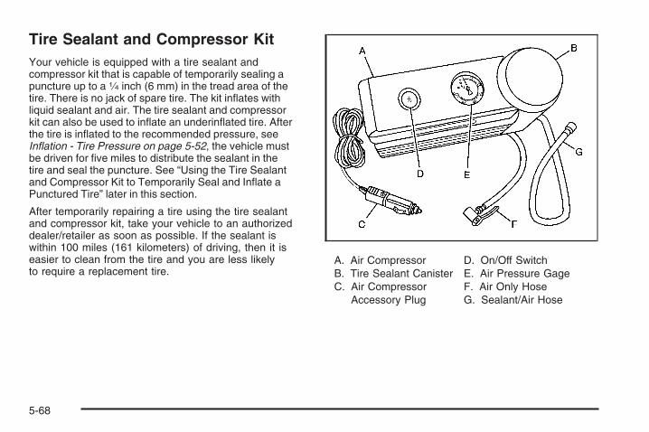
Tire Sealant and Compressor KitYour vehicle is equipped with a tire sealant andcompressor kit that is capable of temporarily sealing apuncture up to a 1⁄4 inch (6 mm) in the tread area of thetire. There is no jack of spare tire. The kit inflates withliquid sealant and air. The tire sealant and compressorkit can also be used to inflate an underinflated tire. Afterthe tire is inflated to the recommended pressure, seeInflation - Tire Pressure on page 5-52, the vehicle mustbe driven for five miles to distribute the sealant in thetire and seal the puncture. See “Using the Tire Sealantand Compressor Kit to Temporarily Seal and Inflate aPunctured Tire” later in this section.
After temporarily repairing a tire using the tire sealantand compressor kit, take your vehicle to an authorizeddealer/retailer as soon as possible. If the sealant iswithin 100 miles (161 kilometers) of driving, then it iseasier to clean from the tire and you are less likelyto require a replacement tire.
A. Air CompressorB. Tire Sealant CanisterC. Air Compressor
Accessory Plug
D. On/Off SwitchE. Air Pressure GageF. Air Only HoseG. Sealant/Air Hose
5-68

Accessing the Tire Sealant andCompressor KitTo access the tire sealant and compressor kit:
1. Open the liftgate. See Liftgate on page 2-9 for moreinformation
2. Lift the forward floor panel of the load floor cargoorganizer.
3. Remove the forward floor panel of the load floorcargo organizer and place it in the vehicle while youare removing the tire sealant and compressor kit.
5-69

4. Open the floor cargo organizer locks, located onthe top left and right corners of the organizer,by pushing inward on them.
5. Remove the load floor cargo organizer.
6. Remove the foam retainer bolt (B) holding down thefoam container.
7. Remove the foam container (C).
8. Remove the sealant and compressor kit (A) from itsfoam container.
5-70

Tire SealantRead and follow the safe handling instructions on theinstructional label adhered to the sealant canister.
Check the tire sealant expiration date on the sealantcanister. The sealant canister should be replaced beforeits expiration date. Replacement canisters are availableat your local dealer/retailer. See “Removal andInstallation of Sealant Canister” later in this section.
The sealant can temporarily seal a puncture up to1⁄4 inch (6 mm) in the tread area of the tire. The sealantcannot seal sidewall damage, large punctures, or a tirethat has become unseated from the wheel. See RoadsideAssistance Program on page 7-6.
The sealant can only be used to seal one tire.After usage, the tire sealant canister and sealant/airhose assembly must be replaced at a dealer/retailer.See “Removal and Installation of Sealant Canister”later in this section.
Using the Tire Sealant and CompressorKit to Temporarily Seal and Inflate aPunctured TireFollow the directions closely for correct sealant usage.
1. Do a safety check before proceeding. See If a TireGoes Flat on page 5-67.
2. Inspect the punctured tire.The sealant can temporarily seal a puncture upto 1⁄4 inch (6 mm) in the tread area of the tire.
5-71

The sealant cannot seal sidewall damage, largepunctures, or a tire that has become unseated fromthe wheel. See Roadside Assistance Program onpage 7-6.Do not remove any objects that have penetratedthe tire.
3. Place the tire sealant and compressor kit on theground and unwrap the sealant/air hose (G) fromthe side of the compressor.
4. Remove the valve stem cap from the flat tire byturning it counterclockwise.
5. Attach the sealant/air hose (G) onto the tire valvestem. Turn it clockwise until it is tight.Make sure the sealant and compressor kit on/offswitch (D) is in the O (off) position.
6. Remove the air compressor accessory plug (C)from the unit.
7. Plug the air compressor accessory plug (C) into anaccessory power outlet in the vehicle. See AccessoryPower Outlet(s) on page 3-17 for more information.Do not slam door or close window on thecompressor accessory plug cord.
{CAUTION:
Idling the engine in a closed-in place or withthe climate control system off can causedeadly carbon monoxide (CO). See EngineExhaust on page 2-29.
8. Start the vehicle. See Starting the Engine(Automatic Engine Start/Stop) on page 2-18for more information. The vehicle must berunning while using the air compressor.
{CAUTION:
Overinflation could cause the tire to rupture,and you or others could be injured. Be sure toread the inflator instructions, and inflate thetire to its recommended pressure. Do notexceed 36 psi (248 kPa).
5-72

9. Push the On/Off switch (D) to the I (on) position.The tire sealant and compressor kit will injectsealant and air into the tire.The pressure gage (E) will initially show a highpressure while the compressor pushes the sealantinto the tire. Once the sealant is completelydispersed into the tire, the pressure will quickly dropand start to rise again as the tire inflates with air only.
10. Inflate the tire to the recommended inflationpressure using the air pressure gage (E) on the topof the unit. The recommended inflation pressurecan be found on the Tire and Loading Informationlabel. See Inflation - Tire Pressure on page 5-52.The pressure gage reading is slightly high while thecompressor is on. Turn the compressor off to getan accurate reading. The compressor may be turnedon and off until the correct pressure is reached.
Notice: If the recommended pressure cannot bereached after 15 minutes, the vehicle should notbe driven farther. Damage to the tire is severe andthe sealant will not be effective. Remove the aircompressor plug from the accessory power outletand unscrew the inflating hose from the tirevalve. See Roadside Assistance Program onpage 7-6 for more information.
11. Turn the compressor off by pushing the On/Offswitch (D) to the O (off) position.Steps 12 through 20 must be done immediatelyafter Step 11.The tire is not sealed and will continue to leakair until the vehicle is driven and the sealantis distributed in the tire.Be careful while handling the tire sealant andcompressor kit as they could be hot after usage.
12. Unplug the air compressor accessory plug (C) fromthe accessory power outlet in the vehicle.
13. Disconnect the sealant/air hose (G) from the tirevalve stem by turning it counterclockwise andreplace the tire valve stem cap.
14. Wrap the sealant/air hose (G) around the aircompressor channel to stow it in its original location.
15. Stow the air compressor accessory plug (C) backin the air compressor. To do this, wrap the aircompressor accessory plug, snap in the plug, andthen push in the bottom and then the top of thewrapped air compressor accessory plug.
5-73

16. If the flat tire wasable to inflate to therecommended inflationpressure, removethe maximum speedlabel from the sealantcanister (B).
17. Place it in a highly visible location such as theinside of the upper left corner of the windshieldor to the face of the radio/clock.The maximum speed label reminds you to drivecautiously and not to exceed 55 mph (90 km/h) untilyou have the damaged tire inspected and repaired.
{CAUTION:
Storing the tire sealant and compressorkit or other equipment in the passengercompartment of the vehicle could cause injury.In a sudden stop or collision, loose equipmentcould strike someone. Store the tire sealantand compressor kit in its original location.
18. Return the equipment to its original storage locationin your vehicle.
19. Immediately drive the vehicle 5 miles (8 km) todistribute the sealant evenly in the tire.
5-74

20. Stop at a safe location and check the tire pressure,refer to Steps 1 through 8 under “Using the TireSealant and Compressor Kit without Sealantto Inflate an Underinflated Tire (Not Punctured)”later in this section.If the tire pressure has fallen more then 10 psi(68 kPa), below the recommended inflation pressure,stop driving the vehicle. The tire is too severelydamaged and the tire sealant and compressor kitcannot seal the tire. See Roadside AssistanceProgram on page 7-6 for more information.If the tire pressure has not dropped more than10 psi (68 kPa) from the recommended inflationpressure, you can inflate the tire back up tothe recommended inflation pressure.
21. Wipe off any sealant from the wheel, tire andvehicle.
22. Dispose of the sealant canister (B) and sealant/airhose (G) assembly at a local dealer/retailer or inaccordance with your local state codes andpractices.
23. After temporarily sealing a tire with the tiresealant and compressor kit, take your vehicleto an authorized dealer/retailer to have the tireinspected and repaired or replaced.
Using the Air Compressor withoutSealant to Inflate an Underinflated Tire(Not Punctured)To use the air compressor to inflate a tire with air onlyand not sealant:
1. Unlock the air only hose (F) from the sealantcanister (B) by pulling up on the lever.
2. Pull the air only hose (F) from the sealantcanister (B).
3. Remove the tire valve stem cap by turning itcounterclockwise.
5-75

4. Push the air only hose (F) onto the tire valve stemand push the lever down to secure in place.
5. Remove the air compressor accessory plug (C)from the unit.
6. Plug the air compressor accessory plug into anaccessory power outlet in the vehicle. See AccessoryPower Outlet(s) on page 3-17 for more information.Do not slam the door or close the window on thecompressor accessory plug cord.
{CAUTION:
Idling the engine in a closed-in place or withthe climate control system off can causedeadly carbon monoxide (CO). See EngineExhaust on page 2-29.
7. Start the vehicle. See Starting the Engine(Automatic Engine Start/Stop) on page 2-18.The vehicle must be running while using theair compressor.
{CAUTION:
Overinflation could cause the tire to rupture,and you or others could be injured. Be sure toread the inflator instructions, and inflate thetire to its recommended pressure. Do notexceed 36 psi (248 kPa).
8. Push the On/Off switch (D) to the I (on) position.The tire sealant and compressor kit will inflate thetire with air only.
9. Inflate the tire to the recommended inflationpressure using the air pressure gage (E) on thetop of the unit. See Inflation - Tire Pressureon page 5-52.The pressure gage reading is slightly high while thecompressor is on. Turn the compressor off to getan accurate pressure reading. The compressor maybe turned on and off until the correct pressure isreached.
10. Turn off the air compressor by pushing the On/Offswitch (D) to the O (off) position.Be careful while handling the tire sealant andcompressor kit as they could be hot after usage.
5-76

11. Unplug the air compressor accessory plug from theaccessory power outlet in the vehicle.
12. Unlock the air only hose (F) from the tire valve stemby pulling the lever up.
13. Disconnect the air only hose (F) from the tire valvestem and replace the tire valve stem cap.
14. Wrap the air only hose (F) around the side of theair compressor channel to stow it back in itsoriginal location.
15. Stow the air compressor accessory plug back in theair compressor. To do this, wrap the air compressoraccessory plug, snap in the plug, and then pushin the bottom and then the top of the wrappedair compressor accessory plug.
16. Return the equipment to its original storage locationof your vehicle.
{CAUTION:
Storing the tire sealant and compressorkit or other equipment in the passengercompartment of the vehicle could cause injury.In a sudden stop or collision, loose equipmentcould strike someone. Store the tire sealantand compressor kit in its original location.
5-77

Removal and Installation of the SealantCanisterTo remove the sealant canister, do the following:
1. Unlock the air only hose from the sealant canisterby pulling the lever up.
2. Unwrap the sealant/air hose from the compressor.
3. Turn the sealant canister so the inflator filling hoseis aligned with the slot in the compressor.
4. Lift the sealant canister from the compressor andreplace with a new sealant canister. See yourdealer/retailer for more information.
5-78

To install a new sealant canister, do the following:
1. Align the sealant/air hose with the slot in the aircompressor.
2. Push the sealant canister down and turn itclockwise.
3. Wrap the sealant/air hose around the aircompressor channel to stow it in its original location.
4. Push the air only hose onto the sealant canister inletand push the lever down.
Appearance Care
Interior CleaningYour vehicle’s interior will continue to look its best if it iscleaned often. Although not always visible, dust and dirtcan accumulate on your upholstery. Dirt can damagecarpet, fabric, leather, and plastic surfaces. Regularvacuuming is recommended to remove particles fromyour upholstery. It is important to keep your upholsteryfrom becoming and remaining heavily soiled. Soils shouldbe removed as quickly as possible. Your vehicle’s interiormay experience extremes of heat that could cause stainsto set rapidly.
Lighter colored interiors may require more frequentcleaning. Use care because newspapers and garmentsthat transfer color to your home furnishings may alsotransfer color to your vehicle’s interior.
When cleaning your vehicle’s interior, only use cleanersspecifically designed for the surfaces being cleaned.Permanent damage may result from using cleaners onsurfaces for which they were not intended. Use glasscleaner only on glass. Remove any accidental over-sprayfrom other surfaces immediately. To prevent over-spray,apply cleaner directly to the cleaning cloth.
Notice: If you use abrasive cleaners when cleaningglass surfaces on your vehicle, you could scratchthe glass and/or cause damage to the rear windowdefogger. When cleaning the glass on yourvehicle, use only a soft cloth and glass cleaner.
Many cleaners contain solvents that may becomeconcentrated in your vehicle’s breathing space.Before using cleaners, read and adhere to all safetyinstructions on the label. While cleaning your vehicle’sinterior, maintain adequate ventilation by openingyour vehicle’s doors and windows.
Dust may be removed from small buttons and knobsusing a small brush with soft bristles.
5-79

Your dealer/retailer has a product for cleaning yourvehicle’s glass. Should it become necessary, you canalso obtain a product from your dealer/retailer to removeodors from your vehicle’s upholstery.
Do not clean your vehicle using:
• A knife or any other sharp object to remove a soilfrom any interior surface.
• A stiff brush. It can cause damage to your vehicle’sinterior surfaces.
• Heavy pressure or aggressive rubbing with acleaning cloth. Use of heavy pressure can damageyour interior and does not improve the effectivenessof soil removal.
• Laundry detergents or dishwashing soaps withdegreasers can leave residue that streaks andattracts dirt. For liquid cleaners, about 20 dropsper gallon (3.78 L) of water is a good guide.Use only mild, neutral-pH soaps.
• Too much cleaner that saturates the upholstery.
• Organic solvents such as naptha, alcohol, etc. thatcan damage your vehicle’s interior.
Fabric/CarpetUse a vacuum cleaner with a soft brush attachmentfrequently to remove dust and loose dirt. A canistervacuum with a beater bar in the nozzle may onlybe used on floor carpet and carpeted floor mats.For any soil, always try to remove it first with plainwater or club soda. Before cleaning, gently remove asmuch of the soil as possible using one of the followingtechniques:
• For liquids: gently blot the remaining soil with apaper towel. Allow the soil to absorb into thepaper towel until no more can be removed.
• For solid dry soils: remove as much as possibleand then vacuum.
To clean:1. Saturate a lint-free, clean white cloth with water or
club soda.2. Wring the cloth to remove excess moisture.3. Start on the outside edge of the soil and gently rub
toward the center. Continue cleaning, using a cleanarea of the cloth each time it becomes soiled.
4. Continue to gently rub the soiled area until thecleaning cloth remains clean.
5. If the soil is not completely removed, use a mildsoap solution and repeat the cleaning processthat was used with plain water.
5-80

If any of the soil remains, a commercial fabric cleaneror spot lifter may be necessary. When a commercialupholstery cleaner or spot lifter is to be used, test a smallhidden area for colorfastness first. If the locally cleanedarea gives any impression that a ring formation mayresult, clean the entire surface.
After the cleaning process has been completed, a papertowel can be used to blot excess moisture from thefabric or carpet.
Instrument Panel, Vinyl, and OtherPlastic SurfacesA soft cloth dampened with water may be used toremove dust. If a more thorough cleaning is necessary,a clean soft cloth dampened with a mild soap solution canbe used to gently remove dust and dirt. Never use spotlifters or removers on plastic surfaces. Many commercialcleaners and coatings that are sold to preserve andprotect soft plastic surfaces may permanently changethe appearance and feel of your interior and are notrecommended. Do not use silicone or wax-basedproducts, or those containing organic solvents toclean your vehicle’s interior because they can alterthe appearance by increasing the gloss in a non-uniformmanner.
Some commercial products may increase gloss onyour instrument panel. The increase in gloss may causeannoying reflections in the windshield and even make itdifficult to see through the windshield under certainconditions.
Care of Safety BeltsKeep belts clean and dry.
{CAUTION:
Do not bleach or dye safety belts. If you do,it may severely weaken them. In a crash,they might not be able to provide adequateprotection. Clean safety belts only with mildsoap and lukewarm water.
5-81

WeatherstripsSilicone grease on weatherstrips will make them lastlonger, seal better, and not stick or squeak. Applysilicone grease with a clean cloth. During very cold,damp weather frequent application may be required.See Recommended Fluids and Lubricants on page 6-12.
Washing Your VehicleThe best way to preserve your vehicle’s finish is to keepit clean by washing it often.
Notice: Certain cleaners contain chemicals that candamage the emblems or nameplates on your vehicle.Check the cleaning product label. If it states that itshould not be used on plastic parts, do not use it onyour vehicle or damage may occur and it would notbe covered by the warranty.
Do not wash the vehicle in direct sunlight. Use a carwashing soap. Do not use cleaning agents that arepetroleum based or that contain acid or abrasives, asthey can damage the paint, metal or plastic on yourvehicle. Approved cleaning products can be obtained
from your dealer/retailer. See Vehicle Care/AppearanceMaterials on page 5-86. Follow all manufacturers’directions regarding correct product usage, necessarysafety precautions and appropriate disposal of anyvehicle care product.
Rinse the vehicle well, before washing and after toremove all cleaning agents completely. If they areallowed to dry on the surface, they could stain.
Dry the finish with a soft, clean chamois or an all-cottontowel to avoid surface scratches and water spotting
High pressure car washes may cause water to enter thevehicle. Avoid using high pressure washes closer than12 inches (30 cm) to the surface of the vehicle. Use ofpower washers exceeding 1,200 psi (8 274 kPa) canresult in damage or removal of paint and decals.
Cleaning Exterior Lamps/LensesUse only lukewarm or cold water, a soft cloth and acar washing soap to clean exterior lamps and lenses.Follow instructions under Washing Your Vehicle onpage 5-82.
5-82

Finish CareOccasional waxing or mild polishing of your vehicle byhand may be necessary to remove residue from thepaint finish. You can get approved cleaning productsfrom your dealer/retailer. See Vehicle Care/AppearanceMaterials on page 5-86.
If your vehicle has a basecoat/clearcoat paint finish,the clearcoat gives more depth and gloss to the coloredbasecoat. Always use waxes and polishes that arenon-abrasive and made for a basecoat/clearcoatpaint finish.
Notice: Machine compounding or aggressivepolishing on a basecoat/clearcoat paint finishmay damage it. Use only non-abrasive waxes andpolishes that are made for a basecoat/clearcoatpaint finish on your vehicle.
Foreign materials such as calcium chloride and othersalts, ice melting agents, road oil and tar, tree sap, birddroppings, chemicals from industrial chimneys, etc., candamage your vehicle’s finish if they remain on paintedsurfaces. Wash the vehicle as soon as possible. Ifnecessary, use non-abrasive cleaners that are markedsafe for painted surfaces to remove foreign matter.
Exterior painted surfaces are subject to aging, weatherand chemical fallout that can take their toll over aperiod of years. You can help to keep the paint finishlooking new by keeping your vehicle garaged or coveredwhenever possible.
Protecting Exterior Bright Metal PartsBright metal parts should be cleaned regularly to keeptheir luster. Washing with water is all that is usuallyneeded. However, you may use chrome polish onchrome or stainless steel trim, if necessary.
Use special care with aluminum trim. To avoid damagingprotective trim, never use auto or chrome polish,steam or caustic soap to clean aluminum. A coating ofwax, rubbed to high polish, is recommended for allbright metal parts.
5-83

Windshield and Wiper BladesClean the outside of the windshield with glass cleaner.
Clean the rubber blades using a lint free cloth orpaper towel soaked with windshield washer fluid ora mild detergent. Wash the windshield thoroughly whencleaning the blades. Bugs, road grime, sap, and abuildup of vehicle wash/wax treatments may causewiper streaking. Replace the wiper blades if they areworn or damaged.
Wipers can be damaged by:
• Extreme dusty conditions
• Sand and salt
• Heat and sun
• Snow and ice, without proper removal
Aluminum WheelsNotice: Chrome wheels and other chrome trim maybe damaged if you do not wash your vehicle afterdriving on roads that have been sprayed withmagnesium, calcium or sodium chloride. Thesechlorides are used on roads for conditions such asice and dust. Always wash your vehicle’s chromewith soap and water after exposure.
Notice: If you use strong soaps, chemicals,abrasive polishes, cleaners, brushes, or cleanersthat contain acid on aluminum or chrome-platedwheels, you could damage the surface of thewheel(s). The repairs would not be covered byyour warranty. Use only approved cleaners onaluminum or chrome-plated wheels.
Keep the wheels clean using a soft clean cloth with mildsoap and water. Rinse with clean water. After rinsingthoroughly, dry with a soft clean towel. A wax may thenbe applied.
5-84

Notice: Using chrome polish on aluminum wheelscould damage the wheels. The repairs would notbe covered by your warranty. Use chrome polishon chrome wheels only.
The surface of these wheels is similar to the paintedsurface of the vehicle. Do not use strong soaps,chemicals, abrasive polishes, abrasive cleaners,cleaners with acid, or abrasive cleaning brusheson them because the surface could be damaged.Do not use chrome polish on aluminum wheels.
Notice: If you drive your vehicle through anautomatic car wash that has silicone carbide tirecleaning brushes, you could damage the aluminumor chrome-plated wheels. The repairs would notbe covered by your warranty. Never drive a vehicleequipped with aluminum or chrome-plated wheelsthrough an automatic car wash that uses siliconecarbide tire cleaning brushes.
TiresTo clean the tires, use a stiff brush with tire cleaner.
Notice: Using petroleum-based tire dressingproducts on your vehicle may damage the paintfinish and/or tires. When applying a tire dressing,always wipe off any overspray from all paintedsurfaces on your vehicle.
Sheet Metal DamageIf the vehicle is damaged and requires sheet metalrepair or replacement, make sure the body repair shopapplies anti-corrosion material to parts repaired orreplaced to restore corrosion protection.
Original manufacturer replacement parts will provide thecorrosion protection while maintaining the warranty.
Finish DamageAny stone chips, fractures or deep scratches in thefinish should be repaired right away. Bare metalwill corrode quickly and may develop into majorrepair expense.
Minor chips and scratches can be repaired with touch-upmaterials available from your dealer/retailer. Largerareas of finish damage can be corrected in yourdealer’s/retailer’s body and paint shop.
5-85

Underbody MaintenanceChemicals used for ice and snow removal and dustcontrol can collect on the underbody. If these arenot removed, corrosion and rust can develop on theunderbody parts such as fuel lines, frame, floor pan,and exhaust system even though they have corrosionprotection.
At least every spring, flush these materials from theunderbody with plain water. Clean any areas where mudand debris can collect. Dirt packed in close areas ofthe frame should be loosened before being flushed.Your dealer/retailer or an underbody car washingsystem can do this for you.
Chemical Paint SpottingSome weather and atmospheric conditions can create achemical fallout. Airborne pollutants can fall upon andattack painted surfaces on your vehicle. This damagecan take two forms: blotchy, ring-shaped discolorations,and small, irregular dark spots etched into the paintsurface.
Although no defect in the paint job causes this, wewill repair, at no charge to the owner, the surfacesof new vehicles damaged by this fallout condition within12 months or 12,000 miles (20 000 km) of purchase,whichever occurs first.
Vehicle Care/Appearance Materials
Description Usage
Polishing ClothWax-Treated
Interior and exteriorpolishing cloth.
Tar and Road OilRemover
Removes tar, road oil,and asphalt.
Chrome Cleaner andPolish
Use on chrome orstainless steel.
White Sidewall TireCleaner
Removes soil and blackmarks from whitewalls.
Vinyl Cleaner Cleans vinyl.
Glass Cleaner Removes dirt, grime,smoke, and fingerprints.
Chrome and Wire WheelCleaner
Removes dirt and grimefrom chrome wheels andwire wheel covers.
Finish Enhancer
Removes dust,fingerprints, and surfacecontaminants. Spray onwipe off.
5-86

Description Usage
Swirl Remover PolishRemoves swirl marks, finescratches, and other lightsurface contamination.
Cleaner Wax Removes light scratchesand protects finish.
Foaming Tire Shine LowGloss
Cleans, shines, andprotects tires. No wipingnecessary.
Wash Wax Concentrate
Medium foamingshampoo. Cleansand lightly waxes.Biodegradable andphosphate free.
Spot LifterRemoves spots and stainsfrom carpets, vinyl, andcloth upholstery.
Odor EliminatorOdorless spray odoreliminator used on fabrics,vinyl, leather, and carpet.
Vehicle Identification
Vehicle Identification Number (VIN)
This is the legal identifier for your vehicle. It appears ona plate in the front corner of the instrument panel, onthe driver side. It can be seen through the windshieldfrom outside the vehicle. The VIN also appears onthe Certification/Tire and Service Parts labels andthe certificates of title and registration.
Engine IdentificationThe eighth character in the VIN is the engine code. Thiscode helps identify the vehicle’s engine, specifications,and replacement parts. See “Engine Specifications”under Capacities and Specifications on page 5-98for your vehicle’s engine code.
5-87
Service Parts Identification LabelThis label is on the inside of the glove box.It is very helpful if you ever need to order parts.The label has the following information:
• Vehicle Identification Number (VIN)
• Model designation
• Paint information
• Production options and special equipment
Do not remove this label from the vehicle.
Electrical System
Intermediate Voltage Devices andWiring
{CAUTION:
Exposure to intermediate voltage can causeshock and burns. The intermediate voltagesystems in your vehicle can only be servicedby technicians with special training.
Intermediate voltage devices are identified bylabels. Do not remove, open, take apart, ormodify these devices. Intermediate voltagecable or wiring has blue covering. Do notprobe, tamper with, cut, or modify intermediatevoltage cable or wiring.
5-88
Add-On Electrical EquipmentNotice: Do not add anything electrical to yourvehicle unless you check with your dealer/retailerfirst. Some electrical equipment can damageyour vehicle and the damage would not be coveredby your warranty. Some add-on electrical equipmentcan keep other components from working as theyshould.
Add-on equipment can drain your vehicle’s battery, evenif your vehicle is not operating.
Your vehicle has an airbag system. Before attempting toadd anything electrical to your vehicle, see ServicingYour Airbag-Equipped Vehicle on page 1-68.
Windshield Wiper FusesThe windshield wiper motor is protected by a circuitbreaker and a fuse. If the motor overheats due to heavysnow, etc., the wiper will stop until the motor cools.If the overload is caused by some electrical problem,have it fixed.
Power Windows and Other PowerOptionsCircuit breakers in the fuse block protect the powerwindows and other power accessories. When the currentload is too heavy, the circuit breaker opens and closes,protecting the circuit until the problem is fixed orgoes away.
5-89

Fuses and Circuit BreakersThe wiring circuits in your vehicle are protected fromshort circuits by fuses. This greatly reduces the chanceof circuit overload and fire caused by electricalproblems.
There are three fuse blocks - the main underhood fuseblock, the auxiliary hybrid underhood fuse block andthe instrument panel fuse block.
To identify and check fuses and relays, refer to theFuse Usage Chart on the inside surface of thefuse panel door.
Instrument Panel Fuse BlockThe instrument panel fuse block is located on thepassenger side of the lower console.
Pull the latch of the fuse box cover straight back toaccess the fuses.
5-90
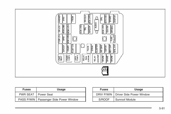
Fuses Usage
PWR SEAT Power Seat
PASS P/WIN Passenger Side Power Window
Fuses Usage
DRIV P/WIN Driver Side Power Window
S/ROOF Sunroof Module
5-91

Fuses Usage
CIGAR Cigarette Lighter
ECM/TCM Engine Control Module (ECM)/Transmission Control Module (TCM)
FSCM Fuel Storage Control Module
ISRVM Inner Side Rearview Mirror)
Cluster Instrument Panel Cluster
AIR BAG Airbag System
OSRVM Outer Side Rearview Mirror
KEY CAP Key Capture Solenoid
WHL S/W Steering Wheel Switch
F/DR LCK Front Driver Door Lock
APO2 Accessory Power Outlet 2
BCM (VB3) Body Control Module (BCM) (VB3)
DR LCK Door Lock
Fuses Usage
BCM (VB6) Body Control Module (VB6)
BCM (VB4) Body Control Module (VB4)
BCM (VB5) Body Control Module (VB5)
TRL Trailer
AIRCON Air Conditioner
AUDIO Audio
BCM (VB7) Body Control Module (VB7)
IGN SW Ignition Switch
AIR BAG Air Bag System
WASHER Washer Pump
APO1 Accessory Power Outlet 1
FSCM Fuel Storage Control Module
RR CLR Rear Closure
5-92
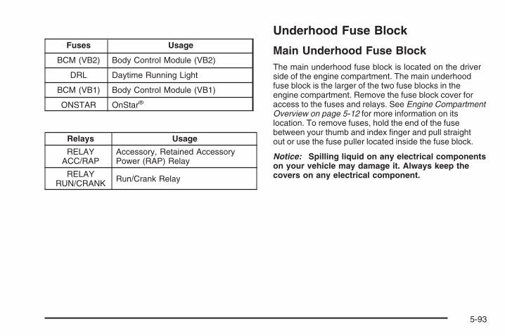
Fuses Usage
BCM (VB2) Body Control Module (VB2)
DRL Daytime Running Light
BCM (VB1) Body Control Module (VB1)
ONSTAR OnStar®
Relays Usage
RELAYACC/RAP
Accessory, Retained AccessoryPower (RAP) Relay
RELAYRUN/CRANK Run/Crank Relay
Underhood Fuse Block
Main Underhood Fuse BlockThe main underhood fuse block is located on the driverside of the engine compartment. The main underhoodfuse block is the larger of the two fuse blocks in theengine compartment. Remove the fuse block cover foraccess to the fuses and relays. See Engine CompartmentOverview on page 5-12 for more information on itslocation. To remove fuses, hold the end of the fusebetween your thumb and index finger and pull straightout or use the fuse puller located inside the fuse block.
Notice: Spilling liquid on any electrical componentson your vehicle may damage it. Always keep thecovers on any electrical component.
5-93

Fuses Usage
ENG 1 Engine 1
ENG 2 Engine 2
Fuses Usage
ECM Engine Control Module
ENG 3 Engine 3
5-94

Fuses Usage
A/C COMP Air Conditioning Compressor
MAINEngine Control Module/CAM,Emissions, Injectors,Electronic Throttle Control
FUEL Fuel Pump
AWD Not Used
ABS Anti-lock Brake SystemModule (ABS)
STOP Stoplamp
HEATING MAT Heating Mat
HORN Horn
WIPER Windshield Wiper
SUNROOF* Sunroof (Option)
ANTI-THEFT* Theft Deterrent System (Option)
POWERSEAT* Power Seat (Option)
Fuses Usage
HDLP LO LH Left Headlamp Low-Beam
HDLP LO RH Right Headlamp Low-Beam
PKLP LH Left Parking Lamp
FRT FOG Front Fog Lamps
H/L HI H/L High
BLANK Not Used
HDLPWASHER Headlamp Washer
TCM Transmission Control Module
T/PKLP L H Left Turn Signal and Parking Lamp
SPARE Spare
SPARE Spare
SPARE Spare
SPARE Spare
5-95

Relays Usage
FAN AUXRELAY Cooling Fan Auxiliary Relay
FUEL RELAY Fuel Pump Relay
WIPER SPEEDRELAY Windshield Wiper Speed Relay
DEFOGRELAY Defogger Relay
HI/LO RELAY High/Low Relay
H/L WASHERRELAY Washer Relay
MAIN RELAYEngine Control Module/CAM,Emissions, Injectors, ElectronicThrottle Control Relay
FAN MAINRELAY Cooling Fan Main Relay
Relays Usage
FANCONTROL
RELAYCooling Fan Control Relay
RUN RELAY Run Relay
PARK LPRELAY Parking Lamp Relay
STARTERRELAY Starter Relay
A/C COMPRELAY Air Conditioning Compressor Relay
HORN RELAY Horn Relay
WIPER RELAY Windshield Wiper Relay
FRT FOGRELAY Front Fog Lamp Relay
H/L HI RELAY H/L High Relay
5-96

Hybrid Underhood Fuse BlockThe Hybrid Underhood Fuse Block is located on thepassenger side of the engine compartment. It is thesmaller of the two fuse blocks in the engine compartment.
Fuses UsageHYBRIDPUMPS Hybrid Pumps
HILL HOLDVLVS Hill Hold Valves
AUXTRANSPUMP Auxiliary Transmission Pump
Relays UsageHILL HOLD
VLVS Hill Hold Valves
AUXTRANSPUMP Auxiliary Transmission Pump
5-97

Capacities and Specifications
ApplicationCapacities
English Metric
Air Conditioning Refrigerant R134a
For the air conditioning system refrigerant chargeamount, see the refrigerant caution label located
under the hood. See your retailer for moreinformation.
Cooling System 9.5 qt 9.0 L
Engine Oil with Filter 5.0 qt 4.7 L
Fuel Tank 18.0 gal 68.1 L
Transmission (Bottom Pan Removal) 6.9 qt 6.5 L
Wheel Nut Torque 100 ft lb 140 Y
All capacities are approximate. When adding, be sure to fill to the approximate level, as recommended in thismanual. Recheck fluid level after filling.
Engine SpecificationsEngine VIN Code Transmission Spark Plug Gap
2.4L L4 Z Automatic 0.040 inches (1.01 mm)
5-98

Maintenance Schedule ......................................6-2Introduction ...................................................6-2Maintenance Requirements ..............................6-2Your Vehicle and the Environment ....................6-2Using the Maintenance Schedule ......................6-2Scheduled Maintenance ...................................6-4Additional Required Services ............................6-6Maintenance Footnotes ...................................6-7
Owner Checks and Services ............................6-8At Each Fuel Fill ............................................6-8At Least Once a Month ...................................6-9At Least Once a Year .....................................6-9Recommended Fluids and Lubricants ...............6-12Maintenance Replacement Parts .....................6-13Engine Drive Belt Routing ..............................6-14Maintenance Record .....................................6-14
Section 6 Maintenance Schedule
6-1

Maintenance Schedule
IntroductionImportant: Keep engine oil at the proper level andchange as recommended.
Maintenance RequirementsNotice: Maintenance intervals, checks, inspections,replacement parts, and recommended fluids andlubricants as prescribed in this manual arenecessary to keep your vehicle in good workingcondition. Any damage caused by failure to followscheduled maintenance might not be coveredby warranty.
Your Vehicle and the EnvironmentProper vehicle maintenance not only helps to keep yourvehicle in good working condition, but also helps theenvironment. All recommended maintenance isimportant. Improper vehicle maintenance can evenaffect the quality of the air we breathe. Improper fluidlevels or the wrong tire inflation can increase the level ofemissions from your vehicle. To help protect ourenvironment, and to keep your vehicle in good condition,be sure to maintain your vehicle properly.
Using the Maintenance ScheduleWe want to help you keep your vehicle in good workingcondition. But we do not know exactly how you willdrive it. You might drive very short distances only a fewtimes a week. Or you might drive long distances allthe time in very hot, dusty weather. You might use yourvehicle in making deliveries. Or you might drive it towork, to do errands, or in many other ways.
Because of all the different ways people use theirvehicles, maintenance needs vary. You might need morefrequent checks and replacements. So please readthe following and note how you drive. If you have anyquestions on how to keep your vehicle in good condition,see your dealer/retailer.
This schedule is for vehicles that:
• carry passengers and cargo within recommendedlimits. You will find these limits on the Tire andLoading Information label. See Loading YourVehicle on page 4-22.
• are driven on reasonable road surfaces within legaldriving limits.
• use the recommended fuel. See Gasoline Octaneon page 5-6.
6-2

The services in Scheduled Maintenance on page 6-4should be performed when indicated. See AdditionalRequired Services on page 6-6 and MaintenanceFootnotes on page 6-7 for further information.
{CAUTION:
Performing maintenance work on a vehicle canbe dangerous. In trying to do some jobs, youcan be seriously injured. Do your ownmaintenance work only if you have therequired know-how and the proper tools andequipment for the job. If you have any doubt,see your dealer/retailer to have a qualifiedtechnician do the work. See Doing Your OwnService Work on page 5-4.
Some maintenance services can be complex. So,unless you are technically qualified and have thenecessary equipment, you should have yourdealer/retailer do these jobs.
When you go to your dealer/retailer for your serviceneeds, you will know that trained and supported servicetechnicians will perform the work using genuine parts.
If you want to purchase service information, see ServicePublications Ordering Information on page 7-14.
Owner Checks and Services on page 6-8 tells you whatshould be checked, when to check it, and what youcan easily do to help keep your vehicle in goodcondition.
The proper replacement parts, fluids, and lubricants touse are listed in Recommended Fluids and Lubricantson page 6-12 and Maintenance Replacement Partson page 6-13. When your vehicle is serviced, make surethese are used. All parts should be replaced and allnecessary repairs done before you or anyone elsedrives the vehicle. We recommend the use of genuineparts from your dealer/retailer.
6-3

Scheduled MaintenanceWhen the Change Engine Oil light comes on, it meansthat service is required for your vehicle. Have yourvehicle serviced as soon as possible within the next 600miles (1 000 km). It is possible that, if you are drivingunder the best conditions, the engine oil life system maynot indicate that vehicle service is necessary for overa year. However, your engine oil and filter must bechanged at least once a year and at this time the systemmust be reset. Your dealer/retailer has trained servicetechnicians who will perform this work using genuineparts and reset the system.
If the engine oil life system is ever reset accidentally,you must service your vehicle within 3,000 miles(5 000 km) since your last service. Remember to resetthe oil life system whenever the oil is changed. SeeEngine Oil Life System on page 5-16 for information onthe Engine Oil Life System and resetting the system.
When the Change Engine Oil light appears, certainservices, checks, and inspections are required. Requiredservices are described in the following for“Maintenance I” and “Maintenance II.” Generally, it isrecommended that your first service be Maintenance I,your second service be Maintenance II, and that youalternate Maintenance I and Maintenance II thereafter.However, in some cases, Maintenance II may berequired more often.
Maintenance I — Use Maintenance I if the ChangeEngine Oil light comes on within 10 months sincethe vehicle was purchased or Maintenance II wasperformed.
Maintenance II — Use Maintenance II if the previousservice performed was Maintenance I. Always useMaintenance II whenever the light comes on 10 monthsor more since the last service or if the light has notcome on at all for one year.
6-4

Scheduled MaintenanceService Maintenance I Maintenance II
Change engine oil and filter. See Engine Oil on page 5-13. Reset oil lifesystem. See Engine Oil Life System on page 5-16. An Emission ControlService.
• •
Visually check for any leaks or damage. See footnote (j). • •Inspect engine air cleaner filter. If necessary, replace filter. See EngineAir Cleaner/Filter on page 5-18. See footnote (l). •
Rotate tires and check inflation pressures and wear. See Tire Inspectionand Rotation on page 5-58 and “Tire Wear Inspection” in At Least Oncea Month on page 6-9.
• •
Inspect brake system. See footnote (a). • •Check engine coolant and windshield washer fluid levels andadd fluid as needed. • •
Perform any needed additional services. See “Additional RequiredServices” in this section. • •
Inspect suspension and steering components. See footnote (b). •Inspect engine cooling system. See footnote (c). •Inspect wiper blades. See footnote (d). •Inspect restraint system components. See footnote (e). •Lubricate body components. See footnote (f). •Replace passenger compartment air filter. See footnote (k). •Inspect throttle system. See footnote (g). •
6-5

Additional Required ServicesThe following services should be performed at the first maintenance service (I or II) after the indicated miles(kilometers) shown for each item.
Additional Required Services
Service and Miles (Kilometers) 25,000(40 000)
50,000(80 000)
75,000(120 000)
100,000(160 000)
125,000(200 000)
150,000(240 000)
Inspect fuel system for damageor leaks. • • • • • •
Inspect exhaust system for loose ordamaged components. • • • • • •
Replace engine air cleaner filter. SeeEngine Air Cleaner/Filter on page 5-18. • • •
Change automatic transmission fluid(severe service). See footnote (h). • • •
Change automatic transmission fluid(normal service). •
Replace spark plugs. An EmissionControl Service. •
Engine cooling system service(or every five years, whichever occursfirst). An Emission Control Service.See footnote (i).
•
Inspect engine accessory drive belt.An Emission Control Service.See footnote (m).
•
6-6

Maintenance Footnotes(a) Visually inspect brake lines and hoses for properhook-up, binding, leaks, cracks, chafing, etc. Inspectdisc brake pads for wear and rotors for surfacecondition. Inspect other brake parts, including calipers,parking brake, etc.
(b) Visually inspect front and rear suspension andsteering system for damaged, loose, or missing parts orsigns of wear.
(c) Visually inspect hoses and have them replaced if theyare cracked, swollen, or deteriorated. Inspect all pipes,fittings, and clamps; replace with genuine parts asneeded. To help ensure proper operation, a pressure testof the cooling system and pressure cap and cleaning theoutside of the radiator and air conditioning condenser isrecommended at least once a year.
(d) Inspect wiper blades for wear, cracking, orcontamination. Clean the windshield and wiper blades, ifcontaminated. Replace wiper blades that are worn ordamaged. See Windshield Wiper Blade Replacement onpage 5-46 and Windshield and Wiper Blades onpage 5-84 for more information.
(e) Make sure the safety belt reminder light and safetybelt assemblies are working properly. Look for anyother loose or damaged safety belt system parts. If yousee anything that might keep a safety belt systemfrom doing its job, have it repaired. Have any torn orfrayed safety belts replaced. Also see Checkingthe Restraint Systems on page 1-70.
(f) Lubricate all key lock cylinders, door hinges andlatches, hood hinges and latches, glove box hinges,sunroof (if equipped), and any folding seat hardware.More frequent lubrication may be required whenexposed to a corrosive environment. Applying siliconegrease on weatherstrips with a clean cloth will makethem last longer, seal better, and not stick or squeak.
(g) Check system for interference or binding andfor damaged or missing parts. Replace parts as needed.Replace any components that have high effort orexcessive wear.
(h) Severe service is when the vehicle is mainly drivenunder one or more of these conditions:
− In heavy city traffic where the outside temperatureregularly reaches 90°F (32°C) or higher.
− In hilly or mountainous terrain.− When doing frequent trailer towing.− Uses such as found in taxi, police, or delivery
service.
6-7

(i) Drain, flush, and refill cooling system. This servicecan be complex; you should have your dealer/retailerperform this service. See Engine Coolant on page 5-20for what to use. Inspect hoses. Clean radiator,condenser, pressure cap, and filler neck. Pressure testthe cooling system and pressure cap.
(j) A fluid loss in any vehicle system could indicate aproblem. Have the system inspected and repaired andthe fluid level checked. Add fluid if needed.
(k) Or every 12 months, whichever occurs first. If youdrive regularly under dusty conditions, the filter mayrequire replacement more often.
(l) If you drive regularly under dusty conditions, inspectthe filter at each engine oil change.
(m) Visually inspect belt for fraying, excessive cracks, orobvious damage. Replace belt if necessary.
Owner Checks and ServicesThese owner checks and services should be performedat the intervals specified to help ensure the safety,dependability, and emission control performance of yourvehicle. Your dealer/retailer can assist you with thesechecks and services.
Be sure any necessary repairs are completed at once.Whenever any fluids or lubricants are added to yourvehicle, make sure they are the proper ones, as shownin Recommended Fluids and Lubricants on page 6-12.
At Each Fuel FillIt is important to perform these underhood checks ateach fuel fill.
Engine Oil Level Check
Notice: It is important to check the engine oilregularly and keep it at the proper level. Failure tokeep the engine oil at the proper level can causedamage to the engine not covered by your warranty.
Check the engine oil level and add the proper oil ifnecessary. See Engine Oil on page 5-13.
6-8

Engine Coolant Level CheckCheck the engine coolant level and add DEX-COOL®
coolant mixture if necessary. See Engine Coolanton page 5-20.
Windshield Washer Fluid Level CheckCheck the windshield washer fluid level in the windshieldwasher fluid reservoir and add the proper fluid ifnecessary.
At Least Once a Month
Tire Inspection and Inflation CheckInspect your vehicle’s tires for wear and make sure theyare inflated to the correct pressures. See Inflation -Tire Pressure on page 5-52.
At Least Once a Year
Starter Switch Check
{CAUTION:
When you are doing this inspection, thevehicle could move suddenly. If the vehiclemoves, you or others could be injured.
1. Before you start, be sure you have enough roomaround the vehicle.
2. Firmly apply both the parking brake and the regularbrake. See Parking Brake on page 2-26.Do not use the accelerator pedal, and be ready toturn off the engine immediately if it starts.
3. Try to start the engine in each gear. The vehicleshould start only in PARK (P) or NEUTRAL (N). Ifthe vehicle starts in any other position, contact yourdealer/retailer for service.
6-9

Automatic Transmission Shift LockControl System Check
{CAUTION:
When you are doing this inspection, thevehicle could move suddenly. If the vehiclemoves, you or others could be injured.
1. Before you start, be sure you have enough roomaround the vehicle. It should be parked on a levelsurface.
2. Firmly apply the parking brake. See Parking Brakeon page 2-26.Be ready to apply the regular brake immediately ifthe vehicle begins to move.
3. With the engine off, turn the ignition to ON/RUN,but do not start the engine. Without applying theregular brake, try to move the shift lever outof PARK (P) with normal effort. If the shift levermoves out of PARK (P), contact your dealer/retailerfor service.
Ignition Transmission Lock CheckWhile parked, and with the parking brake set, try to turnthe ignition to LOCK/OFF in each shift lever position.
• The ignition should turn to LOCK/OFF onlywhen the shift lever is in PARK (P).
• The ignition key should come out only inLOCK/OFF.
Contact your dealer/retailer if service is required.
6-10

Parking Brake and AutomaticTransmission Park (P) MechanismCheck
{CAUTION:
When you are doing this check, your vehiclecould begin to move. You or others could beinjured and property could be damaged. Makesure there is room in front of your vehicle incase it begins to roll. Be ready to apply theregular brake at once should the vehicle beginto move.
Park on a fairly steep hill, with the vehicle facingdownhill. Keeping your foot on the regular brake, set theparking brake.
• To check the parking brake’s holding ability: Withthe engine running and the transmission inNEUTRAL (N), slowly remove foot pressure fromthe regular brake pedal. Do this until the vehicle isheld by the parking brake only.
• To check the PARK (P) mechanism’s holdingability: With the engine running, shift to PARK (P).Then release the parking brake followed by theregular brake.
Contact your dealer/retailer if service is required.
Underbody Flushing ServiceAt least every spring, use plain water to flush anycorrosive materials from the underbody. Take care toclean thoroughly any areas where mud and other debriscan collect.
Tire Sealant and Compressor KitCheck the sealant expiration date printed on theinstruction label of the Tire Sealant and CompressorKit (if equipped) at least once a year. See yourdealer/retailer for a replacement canister.
6-11
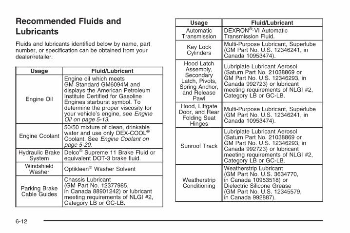
Recommended Fluids andLubricantsFluids and lubricants identified below by name, partnumber, or specification can be obtained from yourdealer/retailer.
Usage Fluid/Lubricant
Engine Oil
Engine oil which meetsGM Standard GM6094M anddisplays the American PetroleumInstitute Certified for GasolineEngines starburst symbol. Todetermine the proper viscosity foryour vehicle’s engine, see EngineOil on page 5-13.
Engine Coolant
50/50 mixture of clean, drinkablewater and use only DEX-COOL®
Coolant. See Engine Coolant onpage 5-20.
Hydraulic BrakeSystem
Delco® Supreme 11 Brake Fluid orequivalent DOT-3 brake fluid.
WindshieldWasher Optikleen® Washer Solvent
Parking BrakeCable Guides
Chassis Lubricant(GM Part No. 12377985,in Canada 88901242) or lubricantmeeting requirements of NLGI #2,Category LB or GC-LB.
Usage Fluid/LubricantAutomatic
TransmissionDEXRON®-VI AutomaticTransmission Fluid.
Key LockCylinders
Multi-Purpose Lubricant, Superlube(GM Part No. U.S. 12346241, inCanada 10953474).
Hood LatchAssembly,Secondary
Latch, Pivots,Spring Anchor,and Release
Pawl
Lubriplate Lubricant Aerosol(Saturn Part No. 21038869 orGM Part No. U.S. 12346293, inCanada 992723) or lubricantmeeting requirements of NLGI #2,Category LB or GC-LB.
Hood, LiftgateDoor, and Rear
Folding SeatHinges
Multi-Purpose Lubricant, Superlube(GM Part No. U.S. 12346241, inCanada 10953474).
Sunroof Track
Lubriplate Lubricant Aerosol(Saturn Part No. 21038869 orGM Part No. U.S. 12346293, inCanada 992723) or lubricantmeeting requirements of NLGI #2,Category LB or GC-LB.
WeatherstripConditioning
Weatherstrip Lubricant(GM Part No. U.S. 3634770,in Canada 10953518) orDielectric Silicone Grease(GM Part No. U.S. 12345579,in Canada 992887).
6-12

Maintenance Replacement PartsReplacement parts identified below by name, part number, or specification can be obtained from your retailer.
Part Saturn Part Number ACDelco Part NumberEngine Air Cleaner/Filter 96815102 —Engine Oil Filter 12605566 PF457GPassenger Compartment Air Filter Element 19130294 —Spark Plugs 1258004 41-103Wiper Blades
Driver’s Side – 24 inches (60.0 cm) 96830172 —Passenger’s Side – 16 inches (40.0 cm) 96830174 —Rear – 12.0 inches (30.0 cm) 96624648 —
6-13
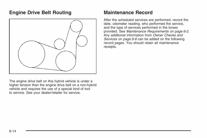
Engine Drive Belt Routing
The engine drive belt on this hybrid vehicle is under ahigher tension than the engine drive belt on a non-hybridvehicle and requires the use of a special kind of toolto service. See your dealer/retailer for service.
Maintenance RecordAfter the scheduled services are performed, record thedate, odometer reading, who performed the service,and the type of services performed in the boxesprovided. See Maintenance Requirements on page 6-2.Any additional information from Owner Checks andServices on page 6-8 can be added on the followingrecord pages. You should retain all maintenancereceipts.
6-14

Maintenance Record
Date OdometerReading Serviced By Maintenance I or
Maintenance II Services Performed
6-15

Maintenance Record (cont’d)
Date OdometerReading Serviced By Maintenance I or
Maintenance II Services Performed
6-16

Maintenance Record (cont’d)
Date OdometerReading Serviced By Maintenance I or
Maintenance II Services Performed
6-17

Maintenance Record (cont’d)
Date OdometerReading Serviced By Maintenance I or
Maintenance II Services Performed
6-18

Customer Assistance and Information ...............7-2Customer Satisfaction Procedure ......................7-2Online Owner Center ......................................7-4Customer Assistance for
Text Telephone (TTY) Users .........................7-4Customer Assistance Offices ............................7-5GM Mobility Reimbursement Program ................7-5Roadside Assistance Program ..........................7-6Scheduling Service Appointments .....................7-8Courtesy Transportation ...................................7-8Collision Damage Repair ................................7-10
Reporting Safety Defects ................................7-13Reporting Safety Defects to the
United States Government ..........................7-13Reporting Safety Defects to the
Canadian Government ................................7-13Reporting Safety Defects to Saturn ..................7-13Service Publications Ordering Information .........7-14
Vehicle Data Recording and Privacy ................7-15Event Data Recorders ...................................7-15OnStar® ......................................................7-16Navigation System ........................................7-16Radio Frequency Identification (RFID) ..............7-16
Section 7 Customer Assistance Information
7-1

Customer Assistance andInformationCustomer Satisfaction ProcedureYour satisfaction and goodwill are important to yourretailer and to Saturn. Together we are committed toproviding our customers with unparalleled service,before, during, and after the purchase of a Saturn vehicle,for total customer satisfaction. We call this the SaturnDifference. Normally, any concerns with the salestransaction or the operation of the vehicle are resolved bythe retailer’s sales or service departments. If, for anyreason, your ownership experience falls below yourexpectations, we suggest you take the following action:
STEP ONE: Contact the Retail Customer AssistanceLiaison. Any member of the retail management team hasthe authority and the desire to resolve your concerns.Normally, concerns can be quickly resolved at this level.
STEP TWO: Should you need additional assistance, inthe U.S., contact the Saturn Customer Assistance Centerby calling 1-800-553-6000. In Canada, call the SaturnCustomer Communication Centre at 1-800-263-1999. ASaturn Customer Assistance Center team member willhandle your call and assist in providing product andwarranty information, the nearest retailer location,roadside assistance, brochures, literature and discussany concerns you may have.
We encourage you to call the toll-free number in order togive your inquiry prompt attention. Please have thefollowing information available to give the CustomerAssistance Representative:• Vehicle Identification Number (VIN). This 17-digit
number can be found on the vehicle registration ortitle, on the upper driver side corner of the instrumentpanel, or on your roadside assistance key card.
• The name of your selling and servicing retail facility.• Vehicle delivery date and present mileage.• Your daytime and evening phone numbers.
When contacting Saturn, please remember that yourconcern will likely be resolved at a retailer’s facility. Thatis why we suggest you follow Step One first.
STEP THREE (U.S. Owners): Both Saturn and itsretailers are committed to making sure you arecompletely satisfied with your Saturn vehicle. However, ifyou continue to remain unsatisfied after following theprocedure outlined in Steps One and Two, Saturn and itsretailers offer the additional assistance of a neutral partythrough our voluntary participation in a mediation/arbitration program called Better Business Bureau (BBB)Auto Line.
The BBB Auto Line Program is an out-of-court programadministered by the Council of Better Business Bureausto settle automotive disputes regarding vehicle repairs orthe interpretation of the New Vehicle Limited Warranty.This program is available at no cost to you, our customer.
7-2

Although you may be required to resort to this informaldispute resolution program prior to filing a court action,use of the program is free of charge and your case isgenerally heard within 40 days. If you do not agree withthe decision given in your case, you can reject it andproceed with any other venue for relief available to you.
Contact the BBB Auto Line Program by using the toll-freetelephone number or by writing them at the followingaddress:
BBB Auto Line ProgramCouncil of Better Business Bureaus, Inc.4200 Wilson BoulevardSuite 800Arlington, VA 22203-1838
Telephone: 1-800-955-5100This program is available in all 50 states and the Districtof Columbia. Eligibility is limited by vehicle age,mileage and other factors. Saturn Corporation reservesthe right to change eligibility limitations and/ordiscontinue its participation in this program.STEP THREE (Canadian Owners):
General Motors Participation in theMediation/Arbitration ProgramIn the event that you do not feel your concerns have beenaddressed after following the procedure outlined in Steps1 and 2, General Motors of Canada Limited hascommitted to binding arbitration of owner disputesinvolving factory-related vehicle service claims.
The program provides for the review of the facts involvedby an impartial third party arbiter, and may include aninformal hearing before the arbiter. The program isdesigned so that the entire dispute settlement process,from the time you file your complaint to the final decision,should be completed in approximately 70 days. Webelieve our impartial program offers advantages overcourts in most jurisdictions because it is informal, quick,and free of charge.
For further information concerning eligibility in theCanadian Motor Vehicle Arbitration Plan (CAMVAP), calltoll-free 1-800-207-0685. Alternatively, you may callthe Saturn Customer Communication Centre,1-800-263-1999, or you may write to:
Mediation/Arbitration Programc/o Customer Communication CentreGeneral Motors of Canada LimitedMail Code: CA1-163-0051908 Colonel Sam DriveOshawa, Ontario L1H 8P7
Telephone: 1-800-955-5100Your inquiry should be accompanied by the VehicleIdentification Number (VIN).
7-3

Online Owner Center(United States only)This is a resource for your Saturn ownership needs.Specific vehicle information can be found in one place.The Online Owner Center allows you to:
• Get e-mail service reminders.
• Access information about your specific vehicle,including tips and videos and an electronicversion of this owner manual.
• Keep track of your vehicle’s service history andmaintenance schedule.
• Find Saturn retailers for service nationwide.
• Receive special promotions and privileges onlyavailable to members.
Refer to www.saturn.com on the web for updatedinformation and to register your vehicle.
My GM Canada (Canada only)My GM Canada is a password-protected section ofgmcanada.com where you can save information onGM vehicles, get personalized offers, and use handytools and forms with greater ease.
Here are a few of the valuable tools and services youwill have access to:
− My Showroom: Find and save information onvehicles and current offers in your area.
− My Dealers/Retailers: Save details such asaddress and phone number for each of yourpreferred GM Dealers or Retailers.
− My Driveway: Receive service reminders andhelpful advice on owning and maintainingyour vehicle.
− My Preferences: Manage your profile, subscribe toE-News and use tools and forms with greater ease.
To sign up, visit the My GM Canada section withinwww.gmcanada.com.
Customer Assistance for TextTelephone (TTY) UsersTo assist owners who have hearing difficulties, Saturnhas installed special TDD (Telecommunication Devicesfor the Deaf) equipment in its Saturn CustomerAssistance Center.
Any hearing or speech-impaired customer whohas access to a TDD or to a conventional TextTelephone (TTY) can communicate with Saturn bydialing 1-800-TDD-6000. TTY users in Canadamay dial 1-800-263-3830.
7-4

Customer Assistance OfficesSaturn encourages customers to call the toll-freenumber for assistance. If a customer wishes to write toSaturn, the letter should be addressed to:
Saturn Customer Assistance Center100 Saturn ParkwayMail Code 371-999-S24Spring Hill, TN 37174-1500
1-800-553-60001-800-833-6000 (For Text Telephonedevices (TTYs))Roadside Assistance: 1-800-553-6000
In Canada, write to:
Saturn Customer Communication CentreGeneral Motors of Canada Ltd.CA1-163-0051908 Colonel Sam DriveOshawa, Ontario L1H 8P7
www.gmcanada.com1-800-263-19991-800-263-3830 (For Text Telephonedevices (TTYs))Roadside Assistance: 1-800-268-6800
GM Mobility ReimbursementProgram
This program, available to qualified applicants, canreimburse you up to $1,000 toward eligible aftermarketdriver or passenger adaptive equipment you mayrequire for your vehicle such as hand controls,wheelchair/scooter lifts, etc.
The offer is available for a limited period of timefrom the date of vehicle purchase/lease.
For more details, or to determine your vehicle’seligibility, visit your Saturn retailer or call the SaturnCustomer Assistance Center at 1-800-553-6000.Text telephone (TTY) users, call 1-800-833-6000.
In Canada, customers may call the SaturnCustomer Communication Centre at 1-800-263-1999.TTY users in Canada may call 1-800-263-3830.
7-5

Roadside Assistance ProgramFor vehicles purchased in the U.S., call 1-800-553-6000;(Text Telephone (TTY): 1-800-889-2438).
For vehicles purchased in Canada, call 1-800-268-6800.
Service is available 24 hours a day, 365 days a year.
As the owner of a new Saturn vehicle, you areautomatically enrolled in the Saturn RoadsideAssistance Program.
Who is Covered?Roadside Assistance coverage is for the vehicleoperator, regardless of ownership. In Canada, a persondriving this vehicle without the consent of the owneris not eligible for coverage.
Services ProvidedThe following services are provided in the U.S. andCanada up to 5 years/100,000 miles (160 000 km),whichever comes first, and, in Canada only, upto a maximum of $100.
• Fuel Delivery: Delivery of enough fuel for thevehicle to get to the nearest service station(approximately $5 Canada). In Canada, service toprovide diesel may be restricted. For safety reasons,propane and other alternative fuels are notprovided through this service.
• Lock-Out Service: Lock-out service is covered atno charge if you are unable to gain entry into yourvehicle. A remote unlock may be available ifyou have an active OnStar® subscription. To ensuresecurity, the driver must present personalidentification before lock-out service is provided. InCanada, the vehicle registration is also required.
• Emergency Tow From a Public Roadway orHighway: Tow to the nearest Saturn retailer forwarranty service or in the event of a vehicle-disablingcrash. Winch-out assistance is provided when thevehicle is mired in sand, mud, or snow.
• Flat Tire Change: Installation of a spare tire in goodcondition, when equipped and properly inflated, iscovered at no charge. The customer is responsiblefor the repair or replacement of the tire if not coveredby a warrantable failure.
• Jump Start: A battery jump start is covered at nocharge if the vehicle does not start.
• Trip Routing Service (Canada Only): Uponrequest, Roadside Assistance will send you detailed,computer personalized maps, highlighting yourchoice of either the most direct route or the mostscenic route to your destination, anywhere in NorthAmerica, along with helpful travel informationpertaining to your trip.
Please allow three weeks before your planneddeparture date. Trip routing requests are limited tosix per calendar year.
7-6

• Trip Interruption Benefits and Assistance(Canada Only): In the event of a warranty relatedvehicle disablement, while en route and over250 kilometres from the original point of departure,you might qualify for trip interruption expenseassistance. This assistance covers reasonablereimbursement of up to a maximum of $500(Canadian) for (A) meals (maximum of $50/day), (B)lodging (maximum of $100/night), and (C) alternateground transportation (maximum of $40/day). Thisbenefit is to assist you with some of the unplannedexpense you may incur while waiting for your vehicleto be repaired.
Pre-authorization, original detailed receipts, and acopy of the repair order are required.Once authorization has been given, your advisor willhelp you make any necessary arrangements andexplain how to claim for trip interruption expenseassistance.
• Alternative Service (Canada Only): There could betimes when Roadside Assistance cannot providetimely assistance. Your advisor may authorize you tosecure local emergency road service, and you will bereimbursed up to $100 upon submission of theoriginal receipt to Roadside Assistance.
In many instances, mechanical failures may be covered.However, any cost for parts and labor for non-warrantyrepairs are the responsibility of the driver.
Saturn and General Motors of Canada Limited reservethe right to limit services or reimbursement to anowner or driver when, in their sole discretion, the claimsbecome excessive in frequency or type of occurrence.
Calling for AssistanceFor prompt and efficient assistance when calling, pleaseprovide the following to the Roadside AssistanceRepresentatives:
• Your name, home address, and home telephonenumber
• Telephone number of your location
• Location of the vehicle
• Model, year, color, and license plate number of thevehicle
• Odometer reading, Vehicle Identification Number(VIN) and delivery date of the vehicle
• Description of the problem
7-7

Towing and Road Service ExclusionsSpecifically excluded from Roadside Assistancecoverage are towing or services for vehicles operated ona non-public roadway or highway, fines, impound towingcaused by a violation of local, Municipal, State, Provincialor Federal law, and mounting, dismounting or changing ofsnow tires, chains, or other traction devices.
Roadside Assistance is not part of or included in thecoverage provided by the New Vehicle Limited Warranty.Saturn and General Motors of Canada Limited reservethe right to make any changes or discontinue theRoadside Assistance program at any time withoutnotification.
Scheduling Service AppointmentsWhen your vehicle requires warranty service, contactyour dealer/retailer and request an appointment.By scheduling a service appointment and advising yourservice consultant of your transportation needs, yourdealer/retailer can help minimize your inconvenience.
If your vehicle cannot be scheduled into the servicedepartment immediately, keep driving it until it can bescheduled for service, unless, of course, the problem issafety-related. If it is, please call your dealership/retailer,let them know this, and ask for instructions.
If the dealer/retailer requests that you simply drop thevehicle off for service, you are urged to do so as early inthe work day as possible to allow for the same day repair.
Courtesy TransportationTo enhance your ownership experience, we and ourparticipating retailers are proud to offer CourtesyTransportation, a customer support program for vehicleswith the Bumper to Bumper (Base Warranty Coverageperiod in Canada) and extended powertrain warrantyin both the U.S. and Canada.
Several courtesy transportation options are available toassist in reducing your inconvenience when warrantyrepairs are required.
Courtesy Transportation is not a part of the New VehicleLimited Warranty. A separate booklet entitled “Warrantyand Owner Assistance Information” furnished witheach new vehicle provides detailed warranty coverageinformation.
7-8

Transportation OptionsWarranty service can generally be completed while youwait. However, if you are unable to wait, Saturn helpsto minimize your inconvenience by providing severaltransportation options. Depending on the circumstances,your retailer can offer you one of the following:
Shuttle ServiceShuttle service is the preferred means of offeringCourtesy Transportation. Retailers may provide you withshuttle service to get you to your destination withminimal interruption of your daily schedule. This includesone-way or round trip shuttle service within reasonabletime and distance parameters of the retailer’s area.
Public Transportation or FuelReimbursementIf your vehicle requires overnight warranty repairs, andpublic transportation is used instead of the retailer’sshuttle service, the expense must be supportedby original receipts and can only be up to the maximumamount allowed by Saturn for shuttle service. Inaddition, for U.S. customers, should you arrangetransportation through a friend or relative, limitedreimbursement for reasonable fuel expenses may beavailable. Claim amounts should reflect actual costs andbe supported by original receipts. See your retailer forinformation regarding the allowance amounts forreimbursement of fuel or other transportation costs.
Courtesy Rental VehicleYour retailer may arrange to provide you with a courtesyrental vehicle or reimburse you for a rental vehiclethat you obtain if your vehicle is kept for an overnightwarranty repair. Rental reimbursement will be limitedand must be supported by original receipts. Thisrequires that you sign and complete a rental agreementand meet state/provincial, local, and rental vehicleprovider requirements. Requirements vary and mayinclude minimum age requirements, insurance coverage,credit card, etc. You are responsible for fuel usagecharges and may also be responsible for taxes, levies,usage fees, excessive mileage, or rental usagebeyond the completion of the repair.
It may not be possible to provide a like-vehicle as acourtesy rental.
Additional Program InformationAll program options, such as shuttle service, may not beavailable at every retailer. Please contact your retailerfor specific information about availability. All CourtesyTransportation arrangements will be administeredby appropriate retailer personnel.
Saturn reserves the right to unilaterally modify, changeor discontinue Courtesy Transportation at any timeand to resolve all questions of claim eligibility pursuantto the terms and conditions described herein at itssole discretion.
7-9

Collision Damage RepairIf your vehicle is involved in a collision and it isdamaged, have the damage repaired by a qualifiedtechnician using the proper equipment and qualityreplacement parts. Poorly performed collision repairsdiminish your vehicle’s resale value, and safetyperformance can be compromised in subsequentcollisions.
Collision PartsGenuine GM Collision parts are new parts made with thesame materials and construction methods as the partswith which your vehicle was originally built. Genuine GMCollision parts are your best choice to ensure that yourvehicle’s designed appearance, durability, and safety arepreserved. The use of Genuine GM parts can helpmaintain your GM New Vehicle Warranty.
Recycled original equipment parts may also be used forrepair. These parts are typically removed from vehiclesthat were total losses in prior crashes. In most cases,the parts being recycled are from undamaged sectionsof the vehicle. A recycled original equipment GMpart, may be an acceptable choice to maintain yourvehicle’s originally designed appearance and safetyperformance, however, the history of these parts is notknown. Such parts are not covered by your GM NewVehicle Limited Warranty, and any related failuresare not covered by that warranty.
Aftermarket collision parts are also available. These aremade by companies other than GM and may not havebeen tested for your vehicle. As a result, these parts mayfit poorly, exhibit premature durability/corrosion problems,and may not perform properly in subsequent collisions.Aftermarket parts are not covered by your GM NewVehicle Limited Warranty, and any vehicle failure relatedto such parts are not covered by that warranty.
Repair FacilityWe recommend that you choose a collision repairfacility that meets your needs before you ever needcollision repairs. Your dealer/retailer may have acollision repair center with GM-trained technicians andstate of the art equipment, or be able to recommenda collision repair center that has GM-trained techniciansand comparable equipment.
Insuring Your VehicleProtect your investment in your GM vehicle withcomprehensive and collision insurance coverage. Thereare significant differences in the quality of coverageafforded by various insurance policy terms. Manyinsurance policies provide reduced protection to your GMvehicle by limiting compensation for damage repairs byusing aftermarket collision parts. Some insurancecompanies will not specify aftermarket collision parts.
7-10

When purchasing insurance, we recommend that youassure your vehicle will be repaired with GM originalequipment collision parts. If such insurance coverage isnot available from your current insurance carrier,consider switching to another insurance carrier.
If your vehicle is leased, the leasing company mayrequire you to have insurance that assures repairs withGenuine GM Original Equipment Manufacturer (OEM)parts or Genuine Manufacturer replacement parts. Readyour lease carefully, as you may be charged at theend of your lease for poor quality repairs.
If a Crash OccursHere is what to do if you are involved in a crash.
• Check to make sure that you are all right. If you areuninjured, make sure that no one else in yourvehicle, or the other vehicle, is injured.
• If there has been an injury, call emergency servicesfor help. Do not leave the scene of a crash until allmatters have been taken care of. Move yourvehicle only if its position puts you in danger or youare instructed to move it by a police officer.
• Give only the necessary and requested informationto police and other parties involved in the crash.Do not discuss your personal condition, mentalframe of mind, or anything unrelated to the crash.This will help guard against post-crash legal action.
• If you need roadside assistance, call GM RoadsideAssistance. See Roadside Assistance Program onpage 7-6 for more information.
• If your vehicle cannot be driven, know where thetowing service will be taking it. Get a card fromthe tow truck operator or write down the driver’sname, the service’s name, and the phone number.
• Remove any valuables from your vehicle before it istowed away. Make sure this includes your insuranceinformation and registration if you keep theseitems in your vehicle.
• Gather the important information you will need fromthe other driver. Things like name, address, phonenumber, driver’s license number, vehicle licenseplate, vehicle make, model and model year, VehicleIdentification Number (VIN), insurance companyand policy number, and a general description of thedamage to the other vehicle.
• If possible, call your insurance company from thescene of the crash. They will walk you throughthe information they will need. If they ask fora police report, phone or go to the policedepartment headquarters the next day and you canget a copy of the report for a nominal fee. Insome states/provinces with “no fault” insurancelaws, a report may not be necessary. This isespecially true if there are no injuries and bothvehicles are driveable.
7-11

• Choose a reputable collision repair facility for yourvehicle. Whether you select a dealer/retailer or aprivate collision repair facility to fix the damage,make sure you are comfortable with them.Remember, you will have to feel comfortable withtheir work for a long time.
• Once you have an estimate, read it carefully andmake sure you understand what work will beperformed on your vehicle. If you have a question,ask for an explanation. Reputable shops welcomethis opportunity.
Managing the Vehicle Damage RepairProcessIn the event that your vehicle requires damage repairs,GM recommends that you take an active role in itsrepair. If you have a pre-determined repair facility ofchoice, take your vehicle there, or have it towed there.Specify to the facility that any required replacementcollision parts be original equipment parts, either newGenuine GM parts or recycled original GM parts.Remember, recycled parts will not be covered by yourGM vehicle warranty.
Insurance pays the bill for the repair, but you must livewith the repair. Depending on your policy limits, yourinsurance company may initially value the repair usingaftermarket parts. Discuss this with your repairprofessional, and insist on Genuine GM parts.Remember if your vehicle is leased you may beobligated to have the vehicle repaired with Genuine GMparts, even if your insurance coverage does not paythe full cost.
If another party’s insurance company is paying for therepairs, you are not obligated to accept a repairvaluation based on that insurance company’s collisionpolicy repair limits, as you have no contractual limits withthat company. In such cases, you can have control ofthe repair and parts choices as long as cost stays withinreasonable limits.
7-12

Reporting Safety Defects
Reporting Safety Defects to theUnited States GovernmentIf you believe that your vehicle has a defect whichcould cause a crash or could cause injury ordeath, you should immediately inform the NationalHighway Traffic Safety Administration (NHTSA),in addition to notifying Saturn Corporation.
If NHTSA receives similar complaints, it couldopen an investigation, and if it finds that a safetydefect exists in a group of vehicles, it couldorder a recall and remedy campaign. However,NHTSA cannot become involved in individualproblems between you, your retailer or SaturnCorporation.
To contact NHTSA, call the Vehicle Safety Hotlinetoll-free at 1-888-327-4236 (TTY: 1-800-424-9153);go to http://www.safercar.gov; or write to:
Administrator, NHTSA400 Seventh Street, SW.Washington D.C., 20590
You can also obtain other information about motorvehicle safety from http://www.safercar.gov.
Reporting Safety Defects to theCanadian GovernmentIf you live in Canada, and you believe that your vehiclehas a safety defect, notify Transport Canadaimmediately, in addition to notifying General Motors ofCanada Limited. Call them at 1-800-333-0510 or write to:
Transport CanadaRoad Safety Branch2780 Sheffield RoadOttawa, Ontario K1B 3V9
Reporting Safety Defects to SaturnIn addition to notifying NHTSA (or Transport Canada) ina situation like this, please notify Saturn.
Call 1-800-553-6000, or write:
Saturn Corporation100 Saturn ParkwayMail Drop 371-999-S24Spring Hill, TN 37174-1500
In Canada, call 1-800-263-1999, or write:
Saturn Customer Communication CentreGeneral Motors of Canada LimitedCA1-163-0051908 Colonel Sam DriveOshawa, Ontario L1H 8P7
7-13
Service Publications OrderingInformation
Service ManualsA variety of publications are available to you. Saturnservice manuals are written for trained technicians, andin some cases, specialized tools and equipment arenecessary to complete certain repairs. However,the manuals are available to owners who either havethe training, or wish to gain a greater understanding ofthe technical aspect of their Saturn.
For additional publications information or to orderpublications in the United States, call toll free1-800-2-SATURN or visit www.saturn-publications.comto order on-line.
In Canada, Saturn service manuals are available bycalling toll free 1-800-551-4123.
Owner PublicationsInformation on how to obtain product bulletins and asdescribed below is applicable only in the fifty U.S. statesand the District of Columbia, and only for cars and lighttrucks with a Gross Vehicle Weight Rating (GVWR) lessthan 10,000 pounds (4 536 kg). Copies of individualbulletins are also at your participating Saturn retailer.You can ask to see them.
In Canada, information relating to product servicebulletins can be obtained by contacting yourSaturn retailer.
Service BulletinsSaturn regularly sends its retailers useful servicebulletins about Saturn products. Saturn monitors productperformance in the field. We then prepare bulletins forservicing our products better. You can get thesebulletins, too.
Bulletins cover various subjects. Some pertain to theproper use and care of your vehicle. Some describecostly repairs. Others describe inexpensive repairswhich, if done on time with the latest parts, may avoidfuture costly repairs.
Some bulletins tell a technician how to repair a new orunexpected condition. Others describe a quickerway to fix your vehicle. They can help a technicianservice your vehicle better.
Most bulletins apply to conditions affecting a smallnumber of vehicles. Your Saturn retailer or a qualifiedtechnician may have to determine if a specificbulletin applies to your vehicle. To order Saturn bulletins,call Saturn Publications at 1-800-2-SATURN or visitwww.saturn-publications.com to order online.
7-14

Vehicle Data Recording andPrivacyYour Saturn vehicle has a number of sophisticatedcomputers that record information about the vehicle’sperformance and how it is driven. For example,your vehicle uses computer modules to monitor andcontrol engine and transmission performance, to monitorthe conditions for airbag deployment and deployairbags in a crash and, if so equipped, to provideantilock braking to help the driver control the vehicle.These modules may store data to help yourdealer/retailer technician service your vehicle. Somemodules may also store data about how you operate thevehicle, such as rate of fuel consumption or averagespeed. These modules may also retain the owner’spersonal preferences, such as radio pre-sets, seatpositions, and temperature settings.
Event Data RecordersThis vehicle has an Event Data Recorder (EDR). Themain purpose of an EDR is to record, in certain crash ornear crash-like situations, such as an airbag deploymentor hitting a road obstacle, data that will assist inunderstanding how a vehicle’s systems performed. TheEDR is designed to record data related to vehicledynamics and safety systems for a short period of time,typically 30 seconds or less. The EDR in this vehicleis designed to record such data as:
• How various systems in your vehicle were operating
• Whether or not the driver and passenger safetybelts were buckled/fastened
• How far, if at all, the driver was pressing theaccelerator and/or brake pedal
• How fast the vehicle was traveling
This data can help provide a better understanding of thecircumstances in which crashes and injuries occur.Important: EDR data is recorded by your vehicle onlyif a non-trivial crash situation occurs; no data isrecorded by the EDR under normal driving conditionsand no personal data (e.g., name, gender, age,and crash location) is recorded. However, other parties,such as law enforcement, could combine the EDRdata with the type of personally identifying data routinelyacquired during a crash investigation.
7-15

To read data recorded by an EDR, special equipment isrequired, and access to the vehicle or the EDR isneeded. In addition to the vehicle manufacturer, otherparties, such as law enforcement, that have the specialequipment, can read the information if they haveaccess to the vehicle or the EDR.
Saturn will not access this data or share it with othersexcept: with the consent of the vehicle owner or, ifthe vehicle is leased, with the consent of the lessee; inresponse to an official request of police or similargovernment office; as part of Saturn’s defense oflitigation through the discovery process; or, as requiredby law. Data that Saturn collects or receives mayalso be used for Saturn research needs or may be madeavailable to others for research purposes, where aneed is shown and the data is not tied to a specificvehicle or vehicle owner.
OnStar®
If your vehicle has OnStar and you subscribe to theOnStar services, please refer to the OnStar Terms andConditions for information on data collection anduse. See also OnStar® System on page 2-33 in thismanual for more information.
Navigation SystemIf your vehicle has a navigation system, use of thesystem may result in the storage of destinations,addresses, telephone numbers, and other tripinformation. Refer to the navigation system operatingmanual for information on stored data and for deletioninstructions.
Radio Frequency Identification(RFID)RFID technology is used in some vehicles for functionssuch as tire pressure monitoring and ignition systemsecurity, as well as in connection with conveniencessuch as key fobs for remote door locking/unlocking andstarting, and in-vehicle transmitters for garage dooropeners. RFID technology in Saturn vehicles does notuse or record personal information or link with any otherSaturn system containing personal information.
7-16

AAbout Driving Your Vehicle ................................... iiiAccessories and Modifications ............................ 5-3Adding Equipment to Your Airbag-Equipped
Vehicle ....................................................... 1-68Additives, Fuel ................................................. 5-7Add-On Electrical Equipment ............................ 5-89Air Cleaner/Filter, Engine ................................. 5-18Air Conditioning .............................................. 3-18Airbag
Passenger Status Indicator ........................... 3-30Readiness Light .......................................... 3-29
Airbag System ................................................ 1-53What Will You See After an Airbag Inflates? ........ 1-62When Should an Airbag Inflate? .................... 1-59Where Are the Airbags? ............................... 1-56
Airbag SystemsAdding Equipment to Your Airbag-Equipped
Vehicle ................................................... 1-68How Does an Airbag Restrain? ...................... 1-61Passenger Sensing System ........................... 1-63Servicing Your Airbag-Equipped Vehicle .......... 1-68What Makes an Airbag Inflate? ...................... 1-61
Antenna, Fixed Mast ....................................... 3-77Antenna, XM™ Satellite Radio Antenna System ..... 3-77Antilock Brake System (ABS) ............................. 4-6
Anti-lock Brake, System Warning Light ............... 3-33Appearance Care
Aluminum Wheels ........................................ 5-84Care of Safety Belts .................................... 5-81Chemical Paint Spotting ............................... 5-86Cleaning Exterior Lamps/Lenses .................... 5-82Fabric/Carpet .............................................. 5-80Finish Care ................................................. 5-83Finish Damage ............................................ 5-85Instrument Panel, Vinyl, and Other Plastic
Surfaces ................................................. 5-81Interior Cleaning .......................................... 5-79Sheet Metal Damage ................................... 5-85Tires .......................................................... 5-85Underbody Maintenance ............................... 5-86Vehicle Care/Appearance Materials ................ 5-86Washing Your Vehicle ................................... 5-82Weatherstrips .............................................. 5-82Windshield and Wiper Blades ........................ 5-84
Appointments, Scheduling Service ....................... 7-8Audio System ................................................. 3-59
Audio Steering Wheel Controls ...................... 3-76Fixed Mast Antenna ..................................... 3-77Radio Reception .......................................... 3-76Setting the Clock ......................................... 3-60XM™ Satellite Radio Antenna System ............ 3-77
1

Audio System(s) ............................................. 3-62Auto Stop Mode ............................................. 3-42Automatic Climate Control System ..................... 3-18Automatic Headlamp System ............................ 3-15Automatic Transmission
Fluid .......................................................... 5-20Operation ................................................... 2-23
BBattery .......................................................... 5-33
Run-Down Protection ................................... 3-17Brake
Emergencies ................................................ 4-6Brakes .......................................................... 5-30
Regenerative Braking ................................... 2-26System Warning Light .................................. 3-32
Braking ........................................................... 4-5Braking in Emergencies ..................................... 4-6Break-In, New Vehicle ..................................... 2-16Bulb Replacement ........................................... 5-41
Front Turn Signal and Parking Lamps ............. 5-43Halogen Bulbs ............................................ 5-41Headlamp Aiming ........................................ 5-39Headlamps ................................................. 5-42License Plate Lamps .................................... 5-45
Bulb Replacement (cont.)Replacement Bulbs ...................................... 5-45Taillamps, Turn Signal, Stoplamps and
Back-up Lamps ........................................ 5-44Buying New Tires ........................................... 5-60
CCalibration ..................................................... 3-48California Fuel .................................................. 5-6California Perchlorate Materials Requirements ....... 5-4California Proposition 65 Warning ....................... 5-4Canadian Owners ................................................ iiCapacities and Specifications ............................ 5-98Carbon Monoxide ........................... 2-29, 4-17, 4-31Care of
Safety Belts ................................................ 5-81Cargo Cover .................................................. 2-43Cargo Management System ............................. 2-44Cargo Tie Downs ............................................ 2-43CD, MP3 ....................................................... 3-70Center Console Storage Area ........................... 2-42Chains, Tire ................................................... 5-66Charge/Assist Gage ........................................ 3-43Charging System Light .................................... 3-32Check
Engine Light ............................................... 3-36
2

Checking Things Under the Hood ...................... 5-10Chemical Paint Spotting ................................... 5-86Child Restraints
Child Restraint Systems ............................... 1-37Infants and Young Children ........................... 1-34Lower Anchors and Tethers for Children .......... 1-41Older Children ............................................. 1-31Securing a Child Restraint in a
Rear Seat Position ................................... 1-47Securing a Child Restraint in the
Right Front Seat Position .......................... 1-49Where to Put the Restraint ........................... 1-39
CleaningAluminum Wheels ........................................ 5-84Exterior Lamps/Lenses ................................. 5-82Fabric/Carpet .............................................. 5-80Finish Care ................................................. 5-83Instrument Panel, Vinyl, and Other Plastic
Surfaces ................................................. 5-81Interior ....................................................... 5-79Tires .......................................................... 5-85Underbody Maintenance ............................... 5-86Washing Your Vehicle ................................... 5-82Weatherstrips .............................................. 5-82Windshield and Wiper Blades ........................ 5-84
Climate Control SystemAir Filter, Passenger Compartment ................. 3-23Automatic ................................................... 3-18Outlet Adjustment ........................................ 3-23
Clock, Setting ................................................. 3-60Collision Damage Repair .................................. 7-10Compass ....................................................... 3-48Compressor Kit, Tire Sealant ............................ 5-68Content Theft-Deterrent .................................... 2-13Control of a Vehicle .......................................... 4-5Convenience Net ............................................ 2-43Coolant
Engine Temperature Warning Light ................. 3-35Heater, Engine ............................................ 2-22Surge Tank Pressure Cap ............................. 5-23
Cooling System .............................................. 5-25Cruise Control ................................................ 3-11Cruise Control Light ........................................ 3-40Cupholders .................................................... 2-42Customer Assistance Information
Courtesy Transportation .................................. 7-8Customer Assistance for Text
Telephone (TTY) Users ............................... 7-4Customer Assistance Offices ........................... 7-5Customer Satisfaction Procedure ..................... 7-2
3

Customer Assistance Information (cont.)GM Mobility Reimbursement Program ............... 7-5Reporting Safety Defects to Saturn ................ 7-13Reporting Safety Defects to the
Canadian Government .............................. 7-13Reporting Safety Defects to the
United States Government ......................... 7-13Roadside Assistance Program ......................... 7-6Service Publications Ordering Information ........ 7-14
DDaytime Running Lamps .................................. 3-15Defensive Driving ............................................. 4-3Delayed Locking ............................................... 2-7DIC Compass ................................................. 3-48Diesel
Running Out of Fuel .................................... 2-30Disc, MP3 ...................................................... 3-70Doing Your Own Service Work ........................... 5-4Dome Lamp ................................................... 3-16Door
Delayed Locking ........................................... 2-7Locks .......................................................... 2-7Power Door Locks ......................................... 2-7Rear Door Security Locks ............................... 2-8
DriverSeat Height Adjuster ...................................... 1-5
Driver Behavior ................................................ 4-2Driver Information Center (DIC) ......................... 3-44
DIC Operation and Displays .......................... 3-44DIC Warnings and Messages ........................ 3-50
DrivingAt Night ..................................................... 4-14Before a Long Trip ...................................... 4-16Defensive ..................................................... 4-3Drunken ....................................................... 4-4Environment ................................................. 4-2Highway Hypnosis ....................................... 4-16Hill and Mountain Roads .............................. 4-16In Rain and on Wet Roads ........................... 4-14Rocking Your Vehicle to Get it Out ................. 4-22Winter ........................................................ 4-17
EEDR ............................................................. 7-15Electrical System
Add-On Equipment ...................................... 5-89Fuses and Circuit Breakers ........................... 5-90Instrument Panel Fuse Block ......................... 5-90Power Windows and Other Power Options ...... 5-89
4

Electrical System (cont.)Underhood Fuse Block ................................. 5-93Windshield Wiper Fuses ............................... 5-89
Electronic ImmobilizerPASS-Key® III ............................................. 2-14
Electronic Immobilizer OperationPASS-Key® III+ ........................................... 2-15
Electronic Stability Program ................................ 4-8Engine
Air Cleaner/Filter ......................................... 5-18Change Engine Oil Light ............................... 3-39Check and Service Engine Soon Light ............ 3-36Coolant ...................................................... 5-20Coolant Heater ............................................ 2-22Coolant Temperature Warning Light ................ 3-35Drive Belt Routing ....................................... 6-14Engine Compartment Overview ...................... 5-12Exhaust ..................................................... 2-29Oil ............................................................. 5-13Oil Life System ........................................... 5-16Overheating ................................................ 5-23Starting ...................................................... 2-18
Entry Lighting ................................................. 3-16Event Data Recorders ..................................... 7-15Extender, Safety Belt ....................................... 1-30Exterior Lamps ............................................... 3-14
FFilter
Engine Air Cleaner ...................................... 5-18Finish Damage ............................................... 5-85Fixed Mast Antenna ........................................ 3-77Flashers, Hazard Warning .................................. 3-6Flash-to-Pass ................................................... 3-8Flat Tire ........................................................ 5-67Fluid
Automatic Transmission ................................ 5-20Windshield Washer ...................................... 5-29
Folding Rear Seat ........................................... 1-10Folding Seatback, Passenger ............................. 1-9Fuel ............................................................... 5-5
Additives ...................................................... 5-7California Fuel .............................................. 5-6Filling a Portable Fuel Container .................... 5-10Filling the Tank ............................................. 5-8Fuels in Foreign Countries .............................. 5-7Gage ......................................................... 3-41Gasoline Octane ........................................... 5-6Gasoline Specifications .................................. 5-6Low Warning Light ....................................... 3-42Running Out of ........................................... 2-30
Fuel Economy Light ........................................ 3-43
5

FusesFuses and Circuit Breakers ........................... 5-90Instrument Panel Fuse Block ......................... 5-90Underhood Fuse Block ................................. 5-93Windshield Wiper ......................................... 5-89
GGage
Fuel .......................................................... 3-41Speedometer .............................................. 3-27Tachometer ................................................. 3-27
Gage, Charge/Assist ........................................ 3-43Garage Door Opener ....................................... 2-36Gasoline
Octane ........................................................ 5-6Specifications ............................................... 5-6
Glove Box ..................................................... 2-41GM Mobility Reimbursement Program .................. 7-5
HHazard Warning Flashers ................................... 3-6Head Restraints ............................................... 1-2Headlamp
Aiming ....................................................... 5-39
Headlamps .................................................... 5-42Bulb Replacement ....................................... 5-41Daytime Running Lamps ............................... 3-15Exterior Lamps ............................................ 3-14Flash-to-Pass ............................................... 3-8Front Turn Signal and Parking Lamps ............. 5-43Halogen Bulbs ............................................ 5-41High/Low Beam Changer ................................ 3-8Wiper Activated ........................................... 3-14
Heated Seats ................................................... 1-6Heater ........................................................... 3-18Height Adjuster, Driver Seat ............................... 1-5Highbeam On Light ......................................... 3-40Highway Hypnosis ........................................... 4-16Hill and Mountain Roads .................................. 4-16Hood
Checking Things Under ................................ 5-10Release ..................................................... 5-11
Horn ............................................................... 3-6How to Wear Safety Belts Properly ................... 1-17
IIgnition Positions ............................................. 2-17Infants and Young Children, Restraints ............... 1-34Inflation - Tire Pressure ................................... 5-52Inflator Kit, Tire ............................................... 5-68
6

Instrument PanelBrightness .................................................. 3-16Cluster ....................................................... 3-26Overview ..................................................... 3-4Storage Area .............................................. 2-42
Intermediate Voltage Devices and Wiring ............ 5-88
JJump Starting ................................................. 5-34
KKeyless Entry System ....................................... 2-4Keys ............................................................... 2-3
LLabeling, Tire Sidewall ..................................... 5-48Lamps
Dome ........................................................ 3-16Reading ..................................................... 3-17
Lap-Shoulder Belt ........................................... 1-25LATCH System
Child Restraints ........................................... 1-41
License Plate Lamps ....................................... 5-45Liftgate
Carbon Monoxide .......................................... 2-9Light
Airbag Readiness ........................................ 3-29Anti-lock Brake System (ABS) Warning ........... 3-33Brake System Warning ................................. 3-32Change Engine Oil ...................................... 3-39Charging System ......................................... 3-32Cruise Control ............................................. 3-40Electronic Stabilitrak Program Indicator ........... 3-34Engine Coolant Temperature Warning ............. 3-35Fuel Economy ............................................. 3-43Highbeam On ............................................. 3-40Low Fuel Warning ....................................... 3-42Low Washer Fluid Warning ........................... 3-40Malfunction Indicator .................................... 3-36Oil Pressure ............................................... 3-38Passenger Airbag Status Indicator .................. 3-30Safety Belt Reminders .................................. 3-28Security ..................................................... 3-40TCS Warning Light ...................................... 3-34Tire Pressure .............................................. 3-35Traction Control System (TCS) Warning .......... 3-34
Light, Auto Stop Mode ..................................... 3-42Lighting
Entry ......................................................... 3-16
7
LightsExterior Lamps ............................................ 3-14Flash-to-Pass ............................................... 3-8High/Low Beam Changer ................................ 3-8
Loading Your Vehicle ....................................... 4-22Lockout Protection ............................................ 2-8Locks
Delayed Locking ........................................... 2-7Door ........................................................... 2-7Lockout Protection ......................................... 2-8Power Door .................................................. 2-7Rear Door Security Locks ............................... 2-8
Loss of Control ............................................... 4-12Low Fuel Warning Light ................................... 3-42Low Washer Fluid Warning Light ....................... 3-40Lumbar
Manual Controls ............................................ 1-6
MMaintenance Schedule
Additional Required Services ........................... 6-6At Each Fuel Fill ........................................... 6-8At Least Once a Month .................................. 6-9At Least Once a Year .................................... 6-9
Maintenance Schedule (cont.)Introduction .................................................. 6-2Maintenance Footnotes .................................. 6-7Maintenance Record .................................... 6-14Maintenance Replacement Parts .................... 6-13Maintenance Requirements ............................. 6-2Owner Checks and Services ........................... 6-8Recommended Fluids and Lubricants ............. 6-12Scheduled Maintenance ................................. 6-4Using .......................................................... 6-2Your Vehicle and the Environment ................... 6-2
Malfunction Indicator Light ................................ 3-36Manual Lumbar Controls .................................... 1-6Manual Reclining Seatbacks ............................... 1-7Manual Seats ................................................... 1-4Manual, Using .................................................... iiiMessage
DIC Warnings and Messages ........................ 3-50Mirrors
Automatic Dimming Rearview ........................ 2-31Manual Rearview ......................................... 2-31Outside Convex Mirror ................................. 2-32Outside Heated Mirrors ................................ 2-32Outside Power Mirrors .................................. 2-32
MP3 ............................................................. 3-70MyGMLink.com ................................................ 7-4
8

NNavigation System, Privacy .............................. 7-16New Vehicle Break-In ...................................... 2-16
OOdometer ...................................................... 3-27Odometer, Trip ............................................... 3-27Off-Road Recovery .......................................... 4-12Oil
Change Engine Oil Light ............................... 3-39Engine ....................................................... 5-13Pressure Light ............................................. 3-38
Oil, Engine Oil Life System .............................. 5-16Older Children, Restraints ................................ 1-31Online Owner Center ........................................ 7-4OnStar, Privacy .............................................. 7-16OnStar® System, see OnStar® Manual ............... 2-33Operation, Universal Home Remote System ........ 2-37Outlet Adjustment ............................................ 3-23Outlets
Accessory Power ......................................... 3-17
OutsideConvex Mirror ............................................. 2-32Heated Mirrors ............................................ 2-32Power Mirrors ............................................. 2-32
Owner Checks and Services .............................. 6-8Owners, Canadian ............................................... ii
PPaint, Damage ............................................... 5-85Park Brake .................................................... 2-26Park (P)
Shifting Into ................................................ 2-27Shifting Out of ............................................ 2-28
ParkingOver Things That Burn ................................. 2-29
Passenger Airbag Status Indicator ..................... 3-30Passenger Compartment Air Filter ..................... 3-23Passenger Sensing System .............................. 1-63Passing ......................................................... 4-12PASS-KEY® III Electronic Immobilizer ................ 2-14PASS-Key® III+ Electronic Immobilizer
Operation ................................................... 2-15Perchlorate Materials Requirements, California ....... 5-4
9

PowerDoor Locks .................................................. 2-7Electrical System ......................................... 5-89Retained Accessory (RAP) ............................ 2-18Seat ............................................................ 1-5Windows .................................................... 2-11
Privacy .......................................................... 7-15Event Data Recorders .................................. 7-15Navigation System ....................................... 7-16OnStar ....................................................... 7-16Radio Frequency Identification ....................... 7-16
RRadio Frequency Identification (RFID), Privacy ...... 7-16Radio(s) ........................................................ 3-62Radios
Reception ................................................... 3-76Setting the Clock ......................................... 3-60
Rainsense™ II Wipers ....................................... 3-9Reading Lamps .............................................. 3-17Rear Door Security Locks .................................. 2-8Rear Seat Armrest .......................................... 2-43Rear Windshield Washer/Wiper ......................... 3-11Rearview Mirror, Automatic Dimming .................. 2-31
Rearview Mirror, Manual .................................. 2-31Reclining Seatbacks, Manual .............................. 1-7Recommended Fluids and Lubricants ................. 6-12Recreational Vehicle Towing ............................. 4-28Regenerative Braking ...................................... 2-26Remote Keyless Entry (RKE) System .................. 2-4Remote Keyless Entry (RKE) System,
Operation ..................................................... 2-5Replacement Bulbs ......................................... 5-45Replacement Parts, Maintenance ...................... 6-13Reporting Safety Defects
Canadian Government .................................. 7-13Saturn ....................................................... 7-13United States Government ............................ 7-13
Restraint System CheckChecking the Restraint Systems .................... 1-70Replacing Restraint System Parts
After a Crash .......................................... 1-71Retained Accessory Power (RAP) ...................... 2-18Roadside
Assistance Program ....................................... 7-6Rocking Your Vehicle to Get it Out .................... 4-22Routing, Engine Drive Belt ............................... 6-14Running Out of Fuel ........................................ 2-30
10

SSafety Belt
Reminder Light ............................................ 3-28Safety Belts
Care of ...................................................... 5-81How to Wear Safety Belts Properly ................ 1-17Lap-Shoulder Belt ........................................ 1-25Safety Belt Extender .................................... 1-30Safety Belt Use During Pregnancy ................. 1-30Safety Belts Are for Everyone ....................... 1-12
Safety Warnings and Symbols .............................. iiiScheduled Maintenance ..................................... 6-4Seatback, Folding Passenger ............................. 1-9Seats
Driver Seat Height Adjuster ............................. 1-5Heated Seats ............................................... 1-6Manual Lumbar ............................................. 1-6Manual Reclining Seatbacks ........................... 1-7Passenger Folding Seatback ........................... 1-9Power Seat .................................................. 1-5Split Folding Rear Seat ................................ 1-10
Securing a Child RestraintRear Seat Position ...................................... 1-47Right Front Seat Position .............................. 1-49
Security Light ................................................. 3-40Service ........................................................... 5-3
Accessories and Modifications ......................... 5-3Adding Equipment to the Outside of Your
Vehicle ..................................................... 5-5California Perchlorate Materials Requirements ..... 5-4California Proposition 65 Warning .................... 5-4Doing Your Own Work ................................... 5-4Engine Soon Light ....................................... 3-36Publications Ordering Information ................... 7-14
Service, Scheduling Appointments ....................... 7-8Servicing Your Airbag-Equipped Vehicle .............. 1-68Setting the Clock ............................................ 3-60Sheet Metal Damage ....................................... 5-85Shifting Into Park (P) ....................................... 2-27Shifting Out of Park (P) ................................... 2-28Signals, Turn and Lane-Change .......................... 3-7Specifications, Capacities ................................. 5-98Speedometer .................................................. 3-27Split Folding Rear Seat .................................... 1-10Stabilitrak Program Indicator Light, Electronic ...... 3-34Starting the Engine ......................................... 2-18Steering .......................................................... 4-9Steering Wheel Controls, Audio ......................... 3-76Steering Wheel, Tilt Wheel ................................. 3-6
11

Storage AreasCargo Management System .......................... 2-44Center Console Storage Area ........................ 2-42Convenience Net ......................................... 2-43Cupholders ................................................. 2-42Glove Box .................................................. 2-41Instrument Panel Storage Area ...................... 2-42Rear Seat Armrest ....................................... 2-43Sunglasses Storage Compartment .................. 2-42
Stuck in Sand, Mud, Ice, or Snow ..................... 4-21Sun Visors ..................................................... 2-12Sunroof ......................................................... 2-44
TTachometer .................................................... 3-27Taillamps
Turn Signal, Stoplamps and Back-up Lamps ...... 5-44TCS Warning Light .......................................... 3-34Theft-Deterrent Systems ................................... 2-13
Content Theft-Deterrent ................................ 2-13PASS-Key® III Electronic Immobilizer .............. 2-14PASS-Key® III+ Electronic Immobilizer
Operation ................................................ 2-15Tilt Wheel ........................................................ 3-6
Time, Setting .................................................. 3-60Tire
Pressure Light ............................................. 3-35Tires ............................................................. 5-47
Aluminum Wheels, Cleaning .......................... 5-84Buying New Tires ........................................ 5-60Chains ....................................................... 5-66Cleaning .................................................... 5-85Different Size .............................................. 5-62If a Tire Goes Flat ....................................... 5-67Inflation - Tire Pressure ................................ 5-52Inspection and Rotation ................................ 5-58Pressure Monitor Operation ........................... 5-55Pressure Monitor System .............................. 5-54Tire Sealant and Compressor Kit ................... 5-68Tire Sidewall Labeling .................................. 5-48Tire Terminology and Definitions .................... 5-50Uniform Tire Quality Grading ......................... 5-62Wheel Alignment and Tire Balance ................. 5-64Wheel Replacement ..................................... 5-64When It Is Time for New Tires ...................... 5-59
TowingRecreational Vehicle ..................................... 4-28Towing a Trailer .......................................... 4-31Your Vehicle ............................................... 4-28
12

TractionControl System (TCS) .................................... 4-7Control System Warning Light ....................... 3-34
TransmissionFluid, Automatic ........................................... 5-20
Transmission Operation, Automatic .................... 2-23Trip Odometer ................................................ 3-27Turn and Lane-Change Signals .......................... 3-7Turn Signal/Multifunction Lever ........................... 3-7
UUniform Tire Quality Grading ............................ 5-62Universal Home Remote System ....................... 2-36
Operation ................................................... 2-37Using this Manual ............................................... iii
VVehicle
Control ........................................................ 4-5Damage Warnings ........................................... ivDesign ......................................................... 4-3Loading ...................................................... 4-22Symbols ......................................................... iv
Vehicle Data Recording and Privacy .................. 7-15Vehicle Identification
Number (VIN) ............................................. 5-87Service Parts Identification Label ................... 5-88
Ventilation Adjustment ...................................... 3-23Visors ........................................................... 2-12
WWarning Lights, Gages and Indicators ................ 3-25Warnings
DIC Warnings and Messages ........................ 3-50Hazard Warning Flashers ............................... 3-6Safety and Symbols ......................................... iiiVehicle Damage .............................................. iv
Washer Fluid, Low Warning Light ...................... 3-40Wheels
Alignment and Tire Balance .......................... 5-64Different Size .............................................. 5-62Replacement ............................................... 5-64
Where to Put the Restraint ............................... 1-39Windows ....................................................... 2-10
Power ........................................................ 2-11
13
WindshieldRainsense™ II Wipers ................................... 3-9Washer ...................................................... 3-10Washer Fluid .............................................. 5-29Wiper Blade Replacement ............................. 5-46Wiper Blades, Cleaning ................................ 5-84Wiper Fuses ............................................... 5-89Wipers ......................................................... 3-8
Windshield, Rear Washer/Wiper ........................ 3-11Winter Driving ................................................ 4-17Wiper Activated Headlamps .............................. 3-14
XXM Radio Messages ....................................... 3-75XM™ Satellite Radio Antenna System ................ 3-77
YYour Driving, the Road and Your Vehicle .............. 4-2Your Vehicle and the Environment ....................... 6-2
14