2005 seismic bracing system -...
TRANSCRIPT
2005 Seismic Bracing SystemSuperstrut Metal Framing
2
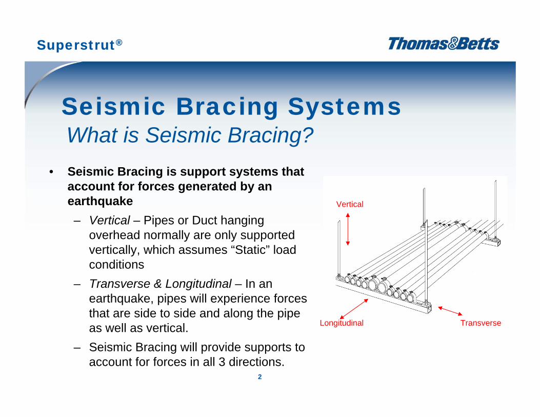
• Seismic Bracing is support systems that account for forces generated by an earthquake– Vertical – Pipes or Duct hanging
overhead normally are only supported vertically, which assumes “Static” load conditions
– Transverse & Longitudinal – In an earthquake, pipes will experience forces that are side to side and along the pipe as well as vertical.
– Seismic Bracing will provide supports to account for forces in all 3 directions.
Seismic Bracing SystemsWhat is Seismic Bracing?
Superstrut®
Vertical
Longitudinal Transverse
3
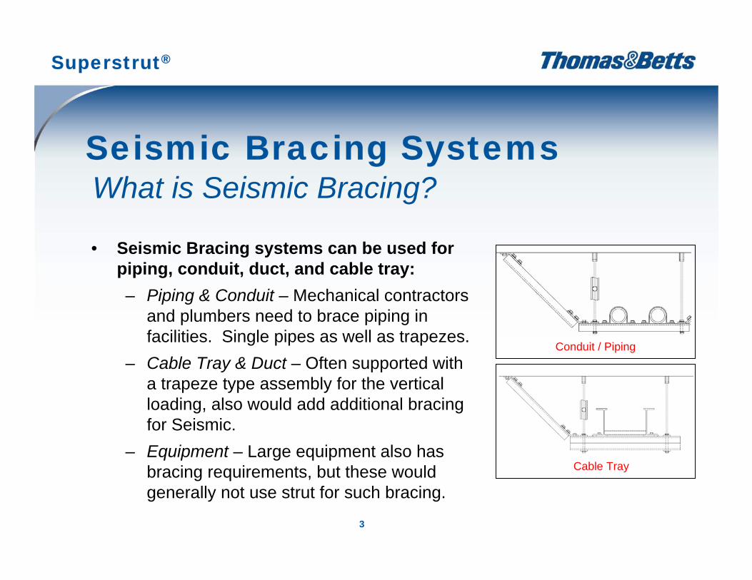
• Seismic Bracing systems can be used for piping, conduit, duct, and cable tray:– Piping & Conduit – Mechanical contractors
and plumbers need to brace piping in facilities. Single pipes as well as trapezes.
– Cable Tray & Duct – Often supported with a trapeze type assembly for the vertical loading, also would add additional bracing for Seismic.
– Equipment – Large equipment also has bracing requirements, but these would generally not use strut for such bracing.
Seismic Bracing SystemsWhat is Seismic Bracing?
Conduit / Piping
Cable Tray
Superstrut®
4
• Different Products that can be used to provide Seismic BracingIn addition to the vertical loading for the pipe or conduit, additional transverse and longitudinal braces are added using a variety of products:– Cable (low product cost, high labor cost)– Pipe (readily available for plumbers)– Strut (electricians and plumbers, low labor cost) T&B Recommends
• Strut is the most cost effective way to provide seismic bracing– The most common applications that would use strut are pipe and
conduit supports.– For such applications, strut is the most cost effective method:
More modular and adaptable than pipeLower labor cost than cable (cable must be attached from two directions to provide the same support as strut)
Seismic Bracing SystemsWhat is Seismic Bracing?
Superstrut®

5
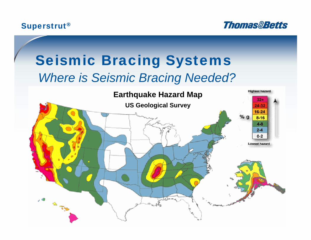
• Certain Geographies Have more Seismic Requirements– The states with areas coded Green, Yellow, or Red normally have building
requirements on the attached map– Enforcement in some states is spotty for Seismic Bracing requirements– Lack of knowledge by installer and inspectors limit use / enforcement of
Seismic Bracing
• Certain Types of Construction have more Seismic Requirements– Government facilities and Hospitals are the most rigid in enforcement of
Seismic requirements– Private Commercial Construction is the least rigid in enforcement of Seismic
requirements– Schools are generally more rigid in enforcement than private commercial
construction
Seismic Bracing SystemsWhere is Seismic Bracing Needed?
Superstrut®
6
Seismic Bracing Systems
Earthquake Hazard MapUS Geological Survey
Where is Seismic Bracing Needed?
Superstrut®
7
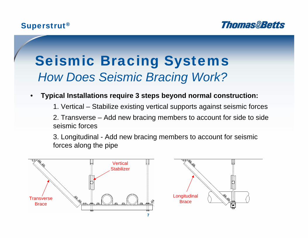
• Typical Installations require 3 steps beyond normal construction:1. Vertical – Stabilize existing vertical supports against seismic forces2. Transverse – Add new bracing members to account for side to side seismic forces3. Longitudinal - Add new bracing members to account for seismic forces along the pipe
Seismic Bracing SystemsHow Does Seismic Bracing Work?
Longitudinal Brace
Transverse Brace
Vertical Stabilizer
Superstrut®
8
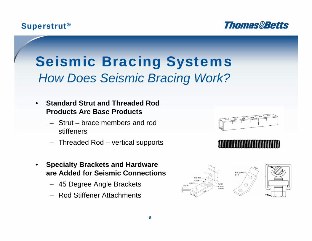
• Standard Strut and Threaded Rod Products Are Base Products– Strut – brace members and rod
stiffeners– Threaded Rod – vertical supports
• Specialty Brackets and Hardware are Added for Seismic Connections– 45 Degree Angle Brackets – Rod Stiffener Attachments
Seismic Bracing SystemsHow Does Seismic Bracing Work?
Superstrut®
9
• OSHPD approval only covers California– The Office of Statewide Health Planning and Development (OSHPD)
is a California agency providing the only pre-approval program in the country
– OSHPD requires the 2001 California Building Code (CBC) be used– Superstrut offers a Bulletin specific to these OSHPD requirements
(GM-????)
• Most States use the IBC– 44 US States utilize the International Building Code (IBC)– Provisions for load calculations and bracing differ between OSHPD
and IBC
Seismic Bracing SystemsWhat Approvals are Required?
Superstrut®
10
• T&B provides an IBC pre-approved system for non-California customers– Recalculating to IBC from OSHPD not required as with most OSHPD pre-
approved systems– Directly apply to your installation– Superstrut offers a Bulletin specific to these IBC requirements (GM-????)
• An Engineer’s Stamp is Normally Required – Most states require the “Engineer of Record” for a given project in a given
location to stamp the design as meeting the engineering requirements of the city / state.
– The Superstrut Seismic Bracing Bulletin provides an easy to use reference for the engineers and contractors to use in designing such systems.
Seismic Bracing SystemsWhat Approvals are Required?
Superstrut®
11
Seismic Bracing SystemsAssembly Design Method Example*
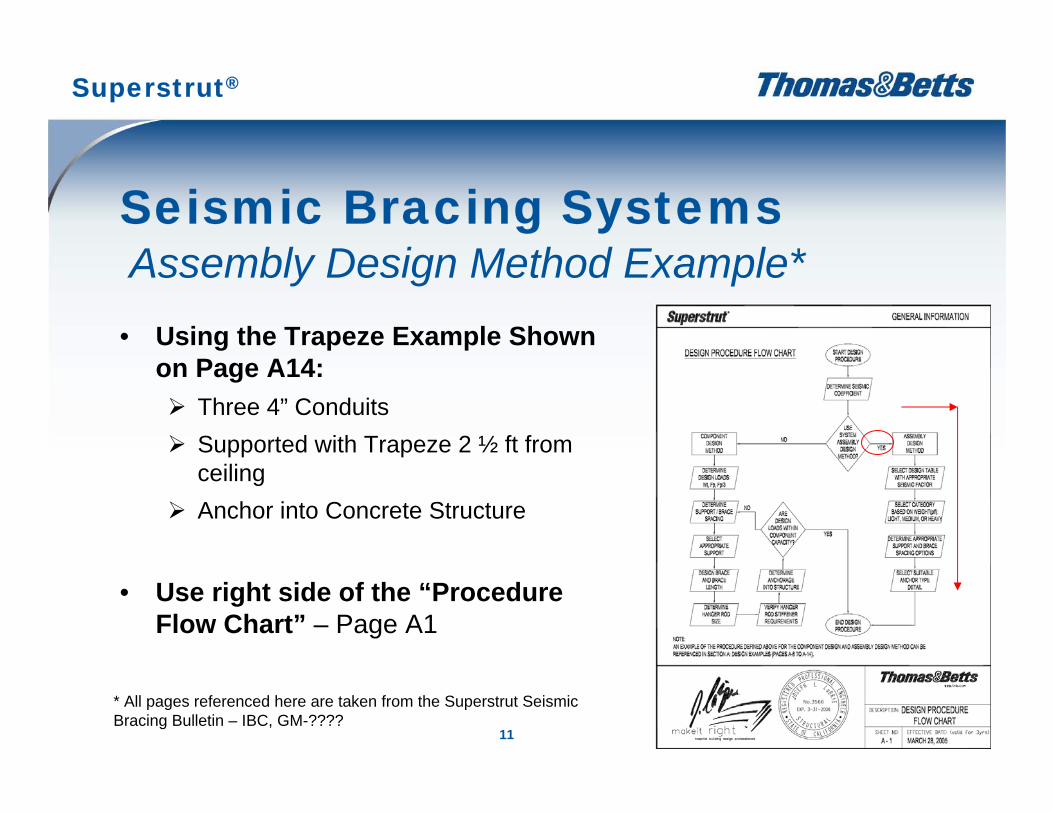
• Using the Trapeze Example Shown on Page A14:
Three 4” Conduits Supported with Trapeze 2 ½ ft from ceilingAnchor into Concrete Structure
• Use right side of the “Procedure Flow Chart” – Page A1
Superstrut®
* All pages referenced here are taken from the Superstrut Seismic Bracing Bulletin – IBC, GM-????
12
Seismic Bracing SystemsAssembly Design Method Example
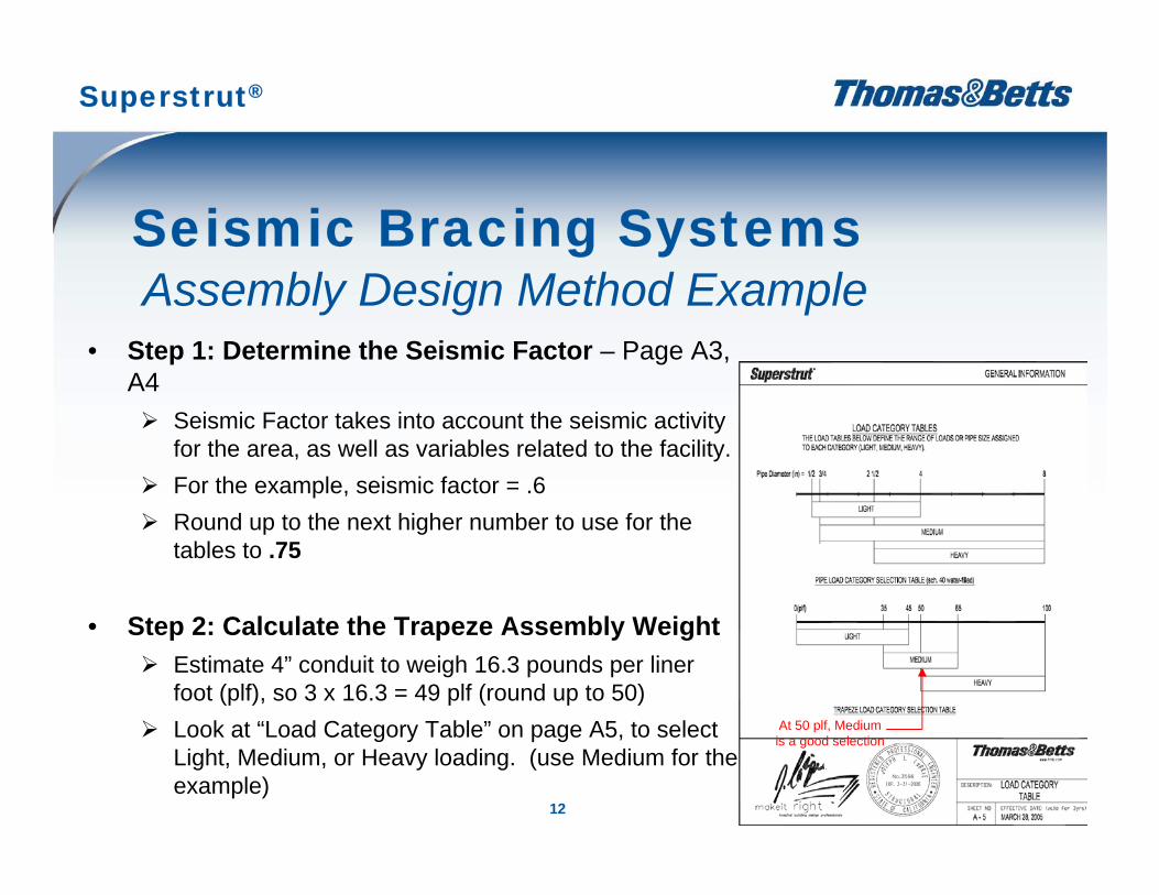
• Step 1: Determine the Seismic Factor – Page A3, A4
Seismic Factor takes into account the seismic activity for the area, as well as variables related to the facility.For the example, seismic factor = .6Round up to the next higher number to use for the tables to .75
• Step 2: Calculate the Trapeze Assembly WeightEstimate 4” conduit to weigh 16.3 pounds per liner foot (plf), so 3 x 16.3 = 49 plf (round up to 50)Look at “Load Category Table” on page A5, to select Light, Medium, or Heavy loading. (use Medium for the example)
At 50 plf, Medium is a good selection
Superstrut®
13
Seismic Bracing SystemsAssembly Design Method Example
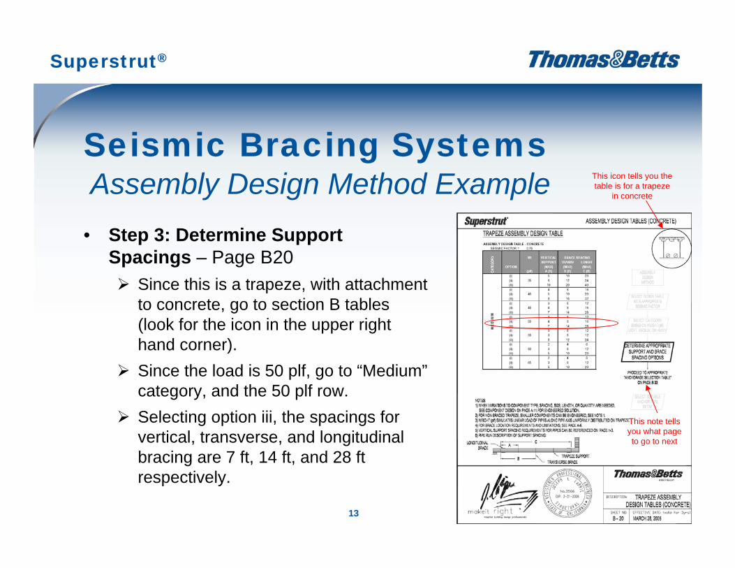
• Step 3: Determine Support Spacings – Page B20
Since this is a trapeze, with attachment to concrete, go to section B tables (look for the icon in the upper right hand corner).Since the load is 50 plf, go to “Medium”category, and the 50 plf row.Selecting option iii, the spacings for vertical, transverse, and longitudinal bracing are 7 ft, 14 ft, and 28 ft respectively.
This icon tells you the table is for a trapeze
in concrete
This note tells you what page to go to next
Superstrut®
14
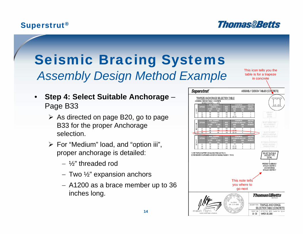
Seismic Bracing SystemsAssembly Design Method Example
• Step 4: Select Suitable Anchorage –Page B33
As directed on page B20, go to page B33 for the proper Anchorage selection.For “Medium” load, and “option iii”, proper anchorage is detailed:− ½” threaded rod− Two ½” expansion anchors− A1200 as a brace member up to 36
inches long.
This icon tells you the table is for a trapeze
in concrete
This note tells you where to
go next
Superstrut®
15
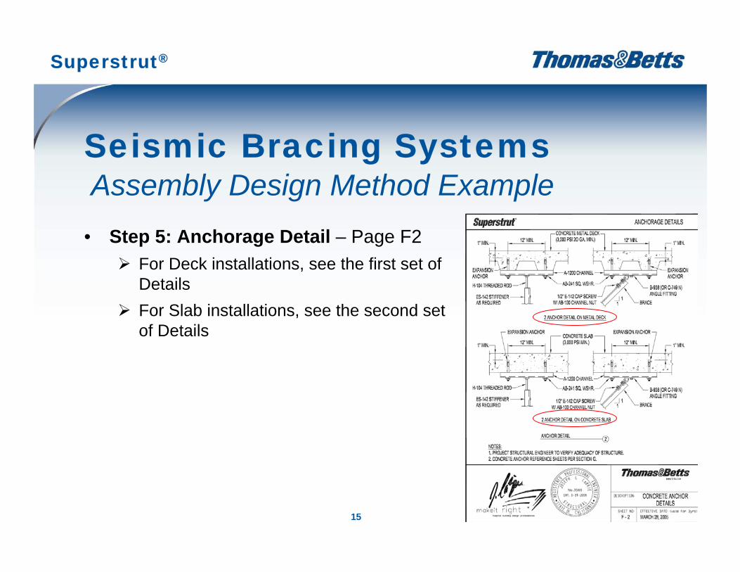
Seismic Bracing SystemsAssembly Design Method Example
• Step 5: Anchorage Detail – Page F2For Deck installations, see the first set of DetailsFor Slab installations, see the second set of Details
Superstrut®
16
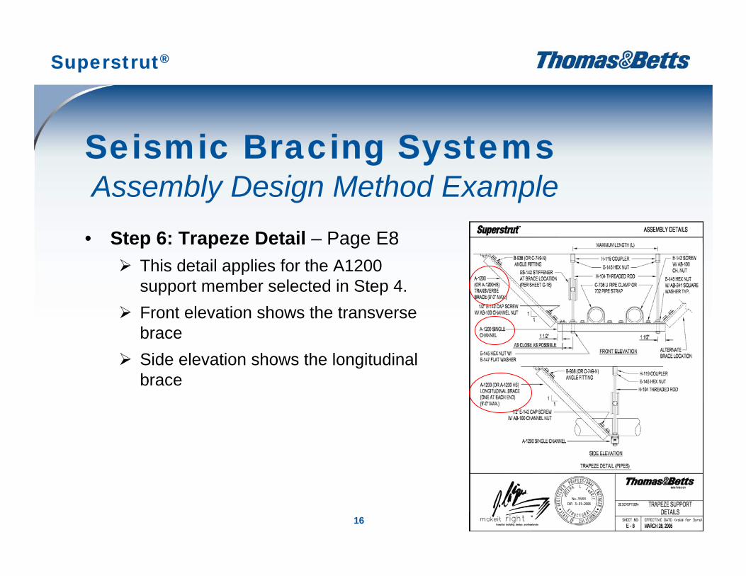
Seismic Bracing SystemsAssembly Design Method Example
• Step 6: Trapeze Detail – Page E8This detail applies for the A1200 support member selected in Step 4.Front elevation shows the transverse braceSide elevation shows the longitudinal brace
Superstrut®
17
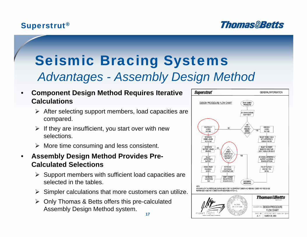
Seismic Bracing SystemsAdvantages - Assembly Design Method
• Component Design Method Requires Iterative Calculations
After selecting support members, load capacities are compared.If they are insufficient, you start over with new selections.More time consuming and less consistent.
• Assembly Design Method Provides Pre-Calculated Selections
Support members with sufficient load capacities are selected in the tables.Simpler calculations that more customers can utilize.Only Thomas & Betts offers this pre-calculated Assembly Design Method system.
Superstrut®
18
• The Superstrut Seismic Bracing System Uses Standard Products– A1200 strut– 702 straps– A100 strut nuts
• Detailed Product Specifications are Provided in Section G– Dimensions and load ratings– Covers all products in the system
Seismic Bracing SystemsThe Superstrut System
Superstrut®
19
• Superstrut Seismic Bracing Bulletin – IBC• Superstrut Seismic Bracing Bulletin – OSHPD• Superstrut Seismic Flyer• Superstrut Seismic Bracing CD• Superstrut Engineering Catalog• Website: www.tnb.com/superstrutseismic
Seismic Bracing SystemsSales Tools
Superstrut®