2004 explorer/mountaineer workshop manual page 1 of 30
TRANSCRIPT

Instrument Cluster (IC) Printable View (606 KB)
Refer to Wiring Diagrams Cell 60 for schematic and connector information.
Inspection and Verification
1. Verify the customer concern.
2. Visually inspect for obvious signs of mechanical or electrical damage.
Visual Inspection Chart
3. If an obvious cause for an observed or reported concern is found, correct the cause (if possible) before proceeding to the next step.
4. If the cause is not visually evident, connect the diagnostic tool to the data link connector and select the vehicle to be tested from the diagnostic tool menu. If the diagnostic tool does not communicate with the vehicle:
� check that the program card is correctly installed.
� check the connections to the vehicle.
� check the ignition switch position.
5. If the diagnostic tool still does not communicate with the vehicle, refer to the diagnostic tool operating manual.
6. Carry out the diagnostic tool data link test. If the diagnostic tool responds with:
� UBP or CAN circuit fault; all electronic control units no response/not equipped, refer to Section 418-00.
� No response/not equipped for the instrument cluster, GO to Pinpoint Test G. For the vehicle security module, refer to Section 418-00; for the anti-lock brake system (ABS), refer to Section 206-09; for the restraint control module (RCM), refer to Section 501-20B.
� System passed, retrieve and record the continuous diagnostic trouble codes (DTCs), erase the continuous DTCs, and carry out self-test diagnostics for the instrument cluster.
7. If the DTCs retrieved are related to the concern, go to the Instrument Cluster Diagnostic Trouble Code (DTC) Index or the Powertrain Control Module (PCM) Diagnostic Trouble Code (DTC) Index to continue diagnostics. For all other DTCs, refer to Section 418-00.
8. If no DTCs related to the concern are retrieved, GO to Symptom Chart to continue diagnostics.
Instrument Cluster Diagnostic Trouble Code (DTC) Index
SECTION 413-00: Information, Gauges and Warning Devices 2004 Explorer/Mountaineer Workshop Manual
DIAGNOSIS AND TESTING Procedure revision date: 02/18/2008
Special Tool(s)
73III Automotive Meter 105-R0057 or equivalent
Instrument Gauge System Tester 014-R1063 or equivalent
Worldwide Diagnostic System (WDS) 418–F224, New Generation STAR (NGS) Tester 418-F052, or equivalent diagnostic tool with appropriate adapter cable
Mechanical Electrical
� Engine oil level � Door adjustment � Engine coolant level � Fuel tank � Fuel evaporative system � Washer fluid level � Brake fluid level
� Battery junction box (BJB) fuse 15 (5A) � Central junction box (CJB) fuse(s):
� 15 (5A) � 21 (5A)
� Miniature bulb(s) � Circuitry � Instrument cluster
DTC Description Source Action
B1201 Fuel Sender Circuit Failure Instrument Cluster
GO to Pinpoint Test H.
B1204 Fuel Sender Circuit Short to Ground Instrument Cluster
GO to Pinpoint Test H.
B1205 Select/Reset Button Assembly Circuit Failure Instrument Cluster
CHECK select/reset button for binding and sticking. GO to Pinpoint Test AN.
B1209 Select/Reset Button Assembly Circuit Failure Instrument Cluster
CHECK select/reset button for binding and sticking. GO to Pinpoint Test AN.
B1255 Air Temperature External Sensor Circuit Open Instrument Cluster
GO to Pinpoint Test AE.
B1257 Air Temperature External Sensor Circuit Short to Ground
Instrument Cluster
GO to Pinpoint Test AE.
Page 1 of 302004 Explorer/Mountaineer Workshop Manual
6/3/2011http://www.fordtechservice.dealerconnection.com/pubs/content/~WS4N/~MUS~LEN/20/S4...

For a complete list of instrument cluster DTCs, refer to Section 418-00.
Powertrain Control Module (PCM) Diagnostic Trouble Code (DTC) Index
For a complete list of PCM DTCs, refer to the Powertrain Control/Emissions Diagnosis (PC/ED) manual.
Instrument Cluster Self-Diagnostic Mode
To enter the instrument cluster self diagnostic mode with the engine off, press and hold the odometer reset button (base cluster) or the message center reset button (message center cluster). Turn the key to the RUN position and hold until the display indicates tESt (base cluster) or TEST (message center cluster) usually within three to five seconds. Press the reset button once to advance through each stage of the self-test.
To exit the instrument cluster self-test mode, turn the ignition to the OFF position. If no DTCs related to the concern are retrieved, GO to Symptom Chart to continue diagnostics.
Instrument Cluster Self-Diagnostic Mode
B1317 Battery Voltage High Instrument Cluster
GO to Pinpoint Test I.
B1318 Battery Voltage Low Instrument Cluster
GO to Pinpoint Test I.
B1342 ECU is Defective Instrument Cluster
INSTALL a new instrument cluster. REFER to Instrument Cluster (IC) in this section. TEST the system for normal operation.
B1345 Heated Backlight Input Circuit Short to Ground Instrument Cluster
REFER to Section 501-00. TEST the system for normal operation.
B1352 Ignition Key-In Circuit Failure Instrument Cluster
GO to Pinpoint Test AV.
B1360 Ignition Run/Acc Circuit Open Instrument Cluster
GO to Pinpoint Test G.
B2143 NVM Memory Failure Instrument Cluster
GO to Pinpoint Test AE.
B2477 Module Configuration Failure Instrument Cluster
REFER to Section 418-00 to continue diagnosis on the module configuration.
B2499 Courtesy Lamp Output Failure Instrument Cluster
REFER to Section 417-02 to continue diagnosis of the courtesy lamps.
B2659 Courtesy Switch Fault Instrument Cluster
REFER to Section 417-02 to continue diagnosis of the courtesy lamps.
C1284 Engine Oil Pressure Switch Failure Instrument Cluster
GO to Pinpoint Test J.
U1900 CAN Communication Bus Fault Instrument Cluster
REFER to Section 418-00 to continue communication diagnosis.
U1950 UBP Communication Bus Fault Instrument Cluster
REFER to Section 418-00 to continue communication diagnosis.
U2013 Compass Module is Not Responding Instrument Cluster
REFER to Information And Message Center in this section.
DTC Description Source Action
P0457 Fuel Fill Cap Off PCM GO to Pinpoint Test P.
P0460 Fuel Level Sensor A Circuit PCM REFER to the Powertrain Control/Emissions Diagnosis (PC/ED) manual first. If sent here from the PC/ED manual, GO to Pinpoint Test H.
P0461 Fuel Level Sensor A Circuit Range/Performance PCM REFER to the Powertrain Control/Emissions Diagnosis (PC/ED) manual first. If sent here from the PC/ED manual, GO to Pinpoint Test H.
P0462 Fuel Level Sensor A Circuit Low PCM REFER to the Powertrain Control/Emissions Diagnosis (PC/ED) manual first. If sent here from the PC/ED manual, GO to Pinpoint Test H.
P0463 Fuel Level Sensor A Circuit High PCM REFER to the Powertrain Control/Emissions Diagnosis (PC/ED) manual first. If sent here from the PC/ED manual, GO to Pinpoint Test H.
Base cluster displayMessage center cluster
display Description
tESt TEST Initial entry display into self-test mode.
GAGE SWEEP GAUGES Carries out gauge sweep of all gauges, then displays the present gauge values. Also carries out the checksum test on ROM and EEPROM.
All segments illuminated All segments illuminated Illuminates all odometer segments.
bulb TEST TELLTALES Illuminates all micro-controlled lamps and LEDs.
— PART NUMBER, ####-10849-##
Displays alpha-numeric part number.
#### — Displays alpha-numeric part number prefix (first four digits).
#### — Suffix (last two digits of the part number are displayed as two byte hexadecimal number).
###### SERIAL NUMBER ###### Displays serial number in decimal.
i9nin# IGNITION KEY, # Displays key-in-ignition status.
r #### ROM LEVEL ####, CHKSUM ####
Returns to normal operation of all micro-controlled lamps and LEDs and displays hexadecimal value for read-only memory (ROM) level.
nr#### NVM LEVEL ##, CHKSUM Displays hexadecimal ROM level and type as stored in non-volatile memory (NVM).
Page 2 of 302004 Explorer/Mountaineer Workshop Manual
6/3/2011http://www.fordtechservice.dealerconnection.com/pubs/content/~WS4N/~MUS~LEN/20/S4...

Symptom Chart
####
EE ## — Displays hexadecimal value for EE level.
dt #### FINAL DATE, #### Displays hexadecimal coding of final manufacturing test date.
CF1-CF4 MODULE CONFIG, BYTE1-BYTE4=##
Displays hexadecimal of bytes 1-4 of module configuration settings.
dtc #### DIAG TROUBLE, CODE: #### Displays a 16-bit DTC in hexadecimal format. DTCs displayed are those detected in continuous operation, not during the self-test.
E ###.# VEHICLE SPEED, ###.# MPH Displays English speed value being input, speedometer will indicate present speed.
###.# VEHICLE SPEED, ###.# KPH Displays metric speed value being input, speedometer will indicate present speed.
t #### TACH VALUE, ####RPM Displays the tachometer value being input to the instrument cluster. Tachometer will indicate present rpm.
F ### FUEL LEVEL A/D, ### Displays present fuel level analog/digital ratio input in decimal. The instrument cluster will indicate present fuel level.
FP ### FUEL LEVEL %, ### Displays present fuel level percent status in decimal.
### C COOLANT TEMP, ### Displays last temperature gauge input value from CAN, temperature gauge will indicate present temperature.
odo### ODO CAN INPUT, ### Displays the odometer input received through CAN in decimal.
OIL### OIL PRESSURE, ### Displays the last analog/digital reading of the engine oil pressure switch contact resistance, oil gauge will indicate present level.
br # BRAKE FLUID AD, # Displays the brake fluid level received from the ABS module.
bAt ##.# BATTERY VOLTS, ##.# Displays present SBATT reading in 10th of volt.
— PWM DIM STEP, ## Displays dimming step in decimal.
rhO ### PWM DIM INPUT , ### Displays present hexadecimal pulse width modulation (PWM) dimming input.
Prnd## PRNDL, ## Displays hexadecimal value of PRNDL inputs packed into a single byte.
Par-# PARK BRAKE, # Displays input status of the park brake switch.
door1-# DOOR AJAR, # Displays input status of any door ajar input.
door2-# LIFTGATE AJAR, # Displays input status of liftgate ajar input.
Stbt-# SEATBELT, # Displays input status of safety belt switch.
— RUN/START, # RUN/START sense circuit check.
— RUN/ACC, # RUN/ACC sense circuit check.
CHE ## CHECK ENGINE, ### Displays 8 bit hexadecimal value of CAN malfunction indicator lamp (MIL) telltale command.
PA, Pb, PE, PG ## PORT A, B, E and J, ## Displays 8-bit hexadecimal value for the ports A, b, E and G (base clusters) or J (message center clusters) readings.
PP, PS, PT, PCAn, PAD0 and PAD1 ##
PORT H, IB, P, S and T, ## Displays 8-bit hexadecimal value for the ports P, S, T, CAn, AD0 and AD1 (base clusters) or H, IB, P, S, and T (message center clusters) in analog/digital readings.
AD00-AD17 ## PORT AD00-AD17 Displays 8-bit hexadecimal value for the ports AD00-AD17 in analog/digital readings.
Symptom Chart
Condition Possible Sources Action
� No communication with the anti-lock brake system (ABS) module
� Central junction box (CJB) fuse 22 (10A). � Circuitry. � Controller area network (CAN) circuits. � ABS module.
� REFER to Section 206-09 to continue communication diagnosis.
� No communication with the vehicle security module
� Central junction box (CJB) fuse 20 (5A). � Circuitry. � Universal asynchronous receiver-transmitter
(UART)-based protocol (UBP) communication network.
� Vehicle security module.
� REFER to Section 418-00 to continue communication diagnosis.
� No communication with the instrument cluster � Circuitry. � Controller area network (CAN) and/or universal
asynchronous receiver-transmitter (UART)-based protocol (UBP) circuits.
� Instrument cluster.
� GO to Pinpoint Test G.
� Incorrect fuel gauge indication � Circuitry. � Fuel level sensor. � Fuel pump module. � Fuel tank. � Instrument cluster.
� GO to Pinpoint Test H.
� Incorrect voltage gauge indication � Circuitry. � Charging system. � Powertrain control module (PCM). � Instrument cluster.
� GO to Pinpoint Test I.
� Incorrect oil pressure gauge indication � Circuitry. � Engine oil pressure switch. � Instrument cluster.
� GO to Pinpoint Test J.
� Incorrect temperature gauge indication � Circuitry. � Electronic coolant temperature (ECT) sensor. � Powertrain control module (PCM). � Instrument cluster.
� GO to Pinpoint Test K.
� The speedometer/odometer is inoperative � Circuitry. � Powertrain control module (PCM). � Instrument cluster.
� GO to Pinpoint Test L.
� The tachometer is inoperative � Circuitry. � Powertrain control module (PCM). � Instrument cluster.
� GO to Pinpoint Test M.
� The door ajar indicator is inoperative (chime is operative)/does not operate correctly
� Circuitry. � Instrument cluster. � Vehicle security module.
� GO to Pinpoint Test N.
Page 3 of 302004 Explorer/Mountaineer Workshop Manual
6/3/2011http://www.fordtechservice.dealerconnection.com/pubs/content/~WS4N/~MUS~LEN/20/S4...

Connector Circuit Reference
Engine Oil Pressure Switch C103
� The safety belt warning indicator is inoperative (chime is operative)/does not operate correctly
� Circuitry. � Restraint control module (RCM). � Safety belt switch (part of the driver belt buckle). � Instrument cluster.
� GO to Pinpoint Test O.
� Inaccurate speedometer reading � Instrument cluster. � Anti-lock brake system (ABS) module. � Tires.
� GO to Pinpoint Test L.
� The CHECK FUEL CAP indicator is never on � Powertrain control module (PCM). � Instrument cluster.
� GO to Pinpoint Test P.
� The CHECK FUEL CAP indicator is always on � Fuel evaporative system. � Powertrain control module (PCM).
� REFER to Powertrain Control/Emissions Diagnosis (PC/ED) manual to continue the diagnosis.
� The anti-lock brake system (ABS) warning indicator is never on
� Circuitry. � Instrument cluster. � Anti-lock brake system (ABS) module.
� GO to Pinpoint Test Q.
� The anti-lock brake system (ABS) warning indicator is always on
� Instrument cluster. � Anti-lock brake system (ABS) module.
� REFER to Section 206-09 to continue diagnosis.
� The brake warning indicator is never/always on � Circuitry. � Brake fluid level switch. � Parking brake switch. � Anti-lock brake system (ABS) module. � Instrument cluster.
� GO to Pinpoint Test R.
� The SERVICE ENGINE SOON indicator is never on
� Powertrain control module (PCM). � Instrument cluster.
� GO to Pinpoint Test S.
� The SERVICE ENGINE SOON indicator is always on
� Diagnostic trouble code (DTC) related concern(s). � REFER to Powertrain Control/Emissions Diagnosis (PC/ED) manual to continue diagnosis.
� The charging system warning indicator is never on
� Charging system. � Circuitry. � Powertrain control module (PCM). � Instrument cluster.
� GO to Pinpoint Test T.
� The charging system warning indicator is always on
� Circuitry. � Generator (charging system). � Powertrain control module (PCM). � Instrument cluster.
� REFER to Section 414-00 to continue diagnosis.
� The air bag indicator warning is never/always on
� Circuitry. � Restraint control module (RCM). � Instrument cluster.
� GO to Pinpoint Test U.
� The high beam indicator is never on � High beam indicator bulb. � Circuitry. � Instrument cluster.
� GO to Pinpoint Test V.
� The LH turn indicator is never on � LH turn indicator bulb. � Circuitry. � Instrument cluster.
� GO to Pinpoint Test W.
� The RH turn indicator is never on � RH turn indicator bulb. � Circuitry. � Instrument cluster.
� GO to Pinpoint Test X.
� The 4X4 HIGH/AWD LOCK range indicator is never/always on
� Circuitry. � Four-wheel drive module. � Instrument cluster.
� GO to Pinpoint Test Y.
� The 4X4 LOW range indicator is never/always on
� Circuitry. � Four-wheel drive module. � Instrument cluster.
� GO to Pinpoint Test Z.
� The speed control indicator is never/always on � Speed control indicator bulb. � Circuitry. � Speed control servo. � Powertrain control module (PCM). � Instrument cluster.
� GO to Pinpoint Test AA.
� The check gauge warning indicator is never/always on
� Circuitry. � Powertrain control module (PCM). � Instrument cluster.
� GO to Pinpoint Test AB.
� The O/D OFF indicator is never/always on � Circuitry. � Powertrain control module (PCM). � Instrument cluster.
� GO to Pinpoint Test AC.
� The traction control indicator is never/always on
� Anti-lock brake system/traction control/interactive vehicle dynamics (ABS/TC/IVD) module.
� Instrument cluster.
� GO to Pinpoint Test AD.
� The integrated circuit display is inoperative � Circuitry. � Instrument cluster.
� If the integrated circuit display is inoperative, GO to Pinpoint Test AE.
� If the temperature display is inoperative, GO to Pinpoint Test AE.
� If the compass is inoperative, GO to Pinpoint Test AL.
� The instrument cluster is inoperative � Circuitry. � Instrument cluster.
� GO to Pinpoint Test AF.
� The low tire warning indicator is never on � Circuitry. � Instrument cluster.
� GO to Pinpoint Test AG.
� The electronic throttle control indicator is never/always on
� Circuitry. � Powertrain control module (PCM). � Instrument cluster.
� GO to Pinpoint Test AH.
Page 4 of 302004 Explorer/Mountaineer Workshop Manual
6/3/2011http://www.fordtechservice.dealerconnection.com/pubs/content/~WS4N/~MUS~LEN/20/S4...
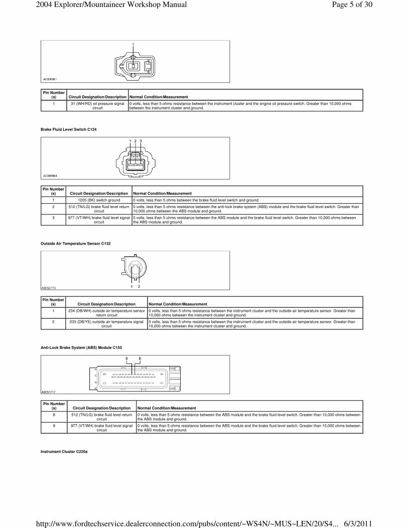
Brake Fluid Level Switch C124
Outside Air Temperature Sensor C132
Anti-Lock Brake System (ABS) Module C155
Instrument Cluster C220a
Pin Number(s) Circuit Designation/Description Normal Condition/Measurement
1 31 (WH/RD) oil pressure signal circuit
0 volts, less than 5 ohms resistance between the instrument cluster and the engine oil pressure switch. Greater than 10,000 ohms between the instrument cluster and ground.
Pin Number(s) Circuit Designation/Description Normal Condition/Measurement
1 1205 (BK) switch ground 0 volts, less than 5 ohms between the brake fluid level switch and ground.
2 512 (TN/LG) brake fluid level return circuit
0 volts, less than 5 ohms resistance between the anti-lock brake system (ABS) module and the brake fluid level switch. Greater than 10,000 ohms between the ABS module and ground.
3 977 (VT/WH) brake fluid level signal circuit
0 volts, less than 5 ohms resistance between the ABS module and the brake fluid level switch. Greater than 10,000 ohms between the ABS module and ground.
Pin Number(s) Circuit Designation/Description Normal Condition/Measurement
1 234 (DB/WH) outside air temperature sensor return circuit
0 volts, less than 5 ohms resistance between the instrument cluster and the outside air temperature sensor. Greater than 10,000 ohms between the instrument cluster and ground.
2 233 (DB/YE) outside air temperature signal circuit
0 volts, less than 5 ohms resistance between the instrument cluster and the outside air temperature sensor. Greater than 10,000 ohms between the instrument cluster and ground.
Pin Number(s) Circuit Designation/Description Normal Condition/Measurement
8 512 (TN/LG) brake fluid level return circuit
0 volts, less than 5 ohms resistance between the ABS module and the brake fluid level switch. Greater than 10,000 ohms between the ABS module and ground.
9 977 (VT/WH) brake fluid level signal circuit
0 volts, less than 5 ohms resistance between the ABS module and the brake fluid level switch. Greater than 10,000 ohms between the ABS module and ground.
Page 5 of 302004 Explorer/Mountaineer Workshop Manual
6/3/2011http://www.fordtechservice.dealerconnection.com/pubs/content/~WS4N/~MUS~LEN/20/S4...

Instrument Cluster C220b
Restraint Control Module (RCM) C310a
Pin Number(s) Circuit Designation/Description Normal Condition/Measurement
1 3049 (BK/LG) B+ keep alive power feed Greater than 10 volts with key ON or OFF. Less than 5 ohms between the instrument cluster and the battery junction box (BJB) and greater than 10,000 ohms between the instrument cluster and ground.
2 1203 (BK/LB) logic ground 0 volts, 5 ohms or less between the instrument cluster and ground.
3 81 (RD/LG) low washer fluid switched ground circuit
0 volts, 5 ohms or less between the instrument cluster and the low washer fluid switch. Greater than 10,000 ohms between the instrument cluster and ground.
7 489 (PK/BK) B+ power feed, hot in the START/RUN positions
Greater than 10 volts. Less than 5 ohms between the instrument cluster and the central junction box (CJB) and greater than 10,000 ohms between the instrument cluster and ground.
13 1390 (DB) safety belt warning indicator control circuit
0 volts, 5 ohms or less between the instrument cluster and the restraint control module. Greater than 10,000 ohms between the instrument cluster and ground.
14 162 (LG/RD) parking brake switch ground control circuit
0 volts, 5 ohms or less between the instrument cluster and the parking brake switch with the parking brake applied. Greater than 10,000 ohms between the instrument cluster and ground with the parking brake released.
16 1392 (LG/OG) RH turn indicator power input
0 volts with the turn indicator in the OFF position. Alternating voltage between 0 volts and 10 volts in the RH turn position. Less than 5 ohms between the instrument cluster and the multifunction switch. Greater than 10,000 ohms between the instrument cluster and ground.
Pin Number(s) Circuit Designation/Description Normal Condition/Measurement
1 1393 (LB/RD) LH turn indicator power input
0 volts with turn indicator in the OFF position. Alternating voltage between 0 volts and 10 volts in the LH turn position. Less than 5 ohms between the instrument cluster and the multifunction switch. Greater than 10,000 ohms between the instrument cluster and ground.
2 1357 (LB/YE) fuel level signal return 0 volts, 5 ohms or less between the instrument cluster and the fuel pump module. Greater than 10,000 ohms between the instrument cluster and ground.
3 608 (BK/YE) air bag warning indicator control circuit.
0 volts, 5 ohms or less between the instrument cluster and the restraint control module. Greater than 10,000 ohms between the instrument cluster and ground.
4 1356 (LG/VT) fuel level variable input signal
0 volts, 5 ohms or less between the instrument cluster and the fuel pump module. Greater than 10,000 ohms between the instrument cluster and ground.
5 31 (WH/RD) oil pressure control ground circuit
0 volts, 5 ohms or less between the instrument cluster and the engine oil pressure switch. Greater than 10,000 ohms between the instrument cluster and ground.
11 1205 (BK) bulb ground circuit 0 volts, less than 5 ohms between the instrument cluster and ground.
13 12 (LG/BK) high beam indicator power input
0 volts with high beams OFF and greater than 10 volts with the high beams in the ON position. Less than 5 ohms between the instrument cluster and the multifunction switch and greater than 10,000 ohms between the instrument cluster and ground.
14 233 (DB/YE) outside air temperature signal circuit
0 volts, less than 5 ohms between the instrument cluster and the outside air temperature sensor and greater than 10,000 ohms between the instrument cluster and ground.
18 295 (LB/PK) B+ power feed in the RUN/ACC position
Greater than 10 volts. Less than 5 ohms resistance between the instrument cluster and the CJB and greater than 10,000 ohms between the instrument cluster and ground.
19 234 (DB/WH) outside air temperature return circuit
0 volts, less than 5 ohms between the instrument cluster and the outside air temperature sensor and greater than 10,000 ohms between the instrument cluster and ground.
Pin Number(s) Circuit Designation/Description Normal Condition/Measurement
19 608 (BK/YE) air bag warning indicator control circuit.
0 volts, less than 5 ohms resistance between the instrument cluster and the air bag module. Greater than 10,000 ohms between the instrument cluster and ground.
22 1390 (DB) safety belt warning indicator control circuit
0 volts, 5 ohms or less between the instrument cluster and the restraint control module. Greater than 10,000 ohms between the instrument cluster and ground.
Page 6 of 302004 Explorer/Mountaineer Workshop Manual
6/3/2011http://www.fordtechservice.dealerconnection.com/pubs/content/~WS4N/~MUS~LEN/20/S4...

Fuel Pump Module C431
Fuel Pump Module C438
Parking Brake Switch C2015
Pinpoint Test G: No Communication With The Instrument Cluster
Normal Operation
Under normal operation the instrument cluster communicates interactively with other electronic modules using the CAN circuits and the UART-based protocol (UBP) communication network. CAN communication is accomplished through the use of an unshielded, twisted pair cable data bus line, circuits 3125 (TN/YE) and 3126 (TN/YE). UBP communication is accomplished through a single data bus line, circuit 693 (OG). For additional information about the communications network, refer to Section 418-00. With the key in the START/RUN position, the instrument cluster receives power from the CJB fuse 21 (5A), circuit 489 (PK/BK). When in the RUN/ACC position, power is received from the CJB fuse 15 (5A), circuit 295 (LB/PK). With the ignition in the OFF position, the instrument cluster receives its keep-alive power from the battery junction box (BJB) fuse 49 (15A), circuit 3049 (BK/LG). The instrument cluster grounding is accomplished through circuit 1203 (BK/LB) and the bulb grounding is accomplished through circuit 1205 (BK).
Possible Causes
� circuit 295 (LB/PK) open or shorted to ground
� circuit 489 (PK/BK) open or shorted to ground
� circuit 1203 (BK/LB) open or shorted to power
� circuit 1205 (BK) open or shorted to power
� circuit 3049 (BK/LG) open or shorted to ground
� instrument cluster
PINPOINT TEST G: NO COMMUNICATION WITH THE INSTRUMENT CLUSTER
Pin Number(s) Circuit Designation/Description Normal Condition/Measurement
2 640 (RD/YE) flex-fuel module B+ power
Greater than 10 volts, less than 5 ohm resistance between the instrument cluster and the fuel pump module. Greater than 10,000 ohms between the instrument cluster and ground.
4 1357 (LB/YE) fuel level signal return 0 volts, 5 ohms or less between the instrument cluster and the fuel pump module. Greater than 10,000 ohms between the instrument cluster and ground.
8 1356 (LG/VT) fuel level variable input signal
0 volts, variable resistance between the instrument cluster and ground from 15 ohms and 160 ohms depending on the position of the float arm with relation to the fuel level.
Pin Number(s) Circuit Designation/Description Normal Condition/Measurement
5 1357 (LB/YE) fuel level signal return 0 volts, 5 ohms or less between the instrument cluster and the fuel pump module. Greater than 10,000 ohms between the instrument cluster and ground.
8 1356 (LG/VT) fuel level variable input signal
0 volts, variable resistance between the instrument cluster and ground from 15 ohms and 160 ohms depending on the position of the float arm with relation to the fuel level.
Pin Number(s) Circuit Designation/Description Normal Condition/Measurement
1 162 (LG/RD) brake warning indicator, parking brake input circuit.
0 volts, less than 5 ohms resistance between the instrument cluster and the parking brake switch. Greater than 10,000 ohms between the instrument cluster and ground.
2 1205 (BK) brake switch ground. 0 volts, less than 5 ohms resistance between the parking brake switch and ground.
Test Step Result / Action to Take
Page 7 of 302004 Explorer/Mountaineer Workshop Manual
6/3/2011http://www.fordtechservice.dealerconnection.com/pubs/content/~WS4N/~MUS~LEN/20/S4...

Pinpoint Test H: Incorrect Fuel Gauge Indication
Normal Operation
The fuel level sender unit is hardwired to the instrument cluster between the signal circuit 1356 (LG/VT) and the return circuit 1357 (LB/YE), which is grounded internally within the instrument cluster. The instrument cluster monitors the resistance readings that are sent from the fuel pump module and commands the fuel gauge with a corresponding movement of the pointer. The instrument cluster sets DTC B1201 if circuit 1356 (LG/VT) is open or shorted to battery. Instrument cluster DTC B1204 is set if circuit 1356 (LG/VT) is shorted to ground.
Instrument Cluster (IC) DTC Chart
PCM DTCs
Possible Causes
� circuit 640 (RD/YE) open
� circuit 1356 (LG/VT) open, short to ground, or short to voltage
� circuit 1357 (LB/YE) open
� fuel tank
� fuel level sensor
� fuel pump module
� instrument cluster
PINPOINT TEST H: INCORRECT FUEL GAUGE INDICATION
NOTICE: Use the correct probe adapter(s) when making measurements. Failure to use the correct probe adapter(s) may damage the connector.
G1 CHECK THE INSTRUMENT CLUSTER POWER SUPPLY
� Ignition OFF. � Disconnect: Instrument Cluster C220a and C220b. � Ignition ON. � Using the following table, measure the voltage between the instrument cluster, harness side and ground.
� Are the voltages greater than 10 volts?
Connector/Pin Circuit
C220b-18 295 (LB/PK)
C220a-1 3049 (BK/LG)
C220a-7 489 (PK/BK)
Yes GO to G2. No REPAIR the circuit(s) in question. TEST the system for normal operation.
G2 CHECK INSTRUMENT CLUSTER GROUND CIRCUITS 1205 (BK) AND 1203 (BK/LB)
� Ignition OFF. � Measure the resistance between the instrument cluster C220b-11, circuit 1205 (BK), harness side and ground; and between the
instrument cluster C220a-2, circuit 1203 (BK/LB), harness side and ground.
� Are the resistances less than 5 ohms?
Yes REFER to Section 418-00 to continue communication diagnosis. No REPAIR the circuit(s) in question. TEST the system for normal operation.
DTC Fault Trigger Conditions
B1201 — Fuel Sender Circuit Failure
A continuous and on-demand DTC that sets if the instrument cluster detects an open or short to voltage for greater then 33 seconds on the fuel level input, circuit 1356 (LG/VT).
B1204 — Fuel Sender Circuit Short To Ground
A continuous and on-demand DTC that sets if the instrument cluster detects a short to ground for greater then 33 seconds on the fuel level input, circuit circuit 1356 (LG/VT) or if circuits 1356 (LG/VT) and 1357 (LB/YE) are shorted together.
DTC Description Fault Trigger Conditions
� P0460 — Fuel Level Sensor A Circuit Sets when the PCM determines the value of the fuel level input signal is stuck, that the fuel level input signal does not change or does not correspond with the calculated fuel usage.
� P0461 — Fuel Level Sensor A Circuit Range/Performance
Sets when the PCM determines the fuel level input signal repeatedly moves in and out of range, exceeding the minimum or maximum allowable calibrated parameters for a specified fuel fill percentage in the fuel tank.
� P0462 — Fuel Level Sensor A Circuit Low Sets in the PCM when the PCM detects a short to ground on the fuel pump module signal circuit based on the messaged input received from the instrument cluster.
� P0463 — Fuel Level Sensor A Circuit High Sets in the PCM when the PCM detects an open or a short to voltage on the fuel pump module signal circuit based on the messaged input received from the instrument cluster.
Test Step Result / Action to Take
H1 CARRY OUT THE INSTRUMENT CLUSTER FUEL GAUGE ACTIVE COMMAND USING THE DIAGNOSTIC TOOL
� Ignition ON. � Enter the following diagnostic mode on the scan tool: Instrument Cluster Active Command. � Select the instrument cluster fuel level control active command. Trigger, monitor, and scroll the fuel level at: 0% , 50%,
and 100%. � Does the fuel gauge display: below E with 0%, half with 50%, and full stop with 100%?
Yes GO to H2. No GO to H10.
Page 8 of 302004 Explorer/Mountaineer Workshop Manual
6/3/2011http://www.fordtechservice.dealerconnection.com/pubs/content/~WS4N/~MUS~LEN/20/S4...

H2 CHECK THE FUEL GAUGE OPERATION
� Ignition OFF. � NOTE: The fuse must be removed to reset the fuel gauge timers. Failure to complete this step may result in erroneous
test results. � Remove the battery junction box (BJB) fuse 15 (15A). Wait 1 minute and reinstall the fuse. � Disconnect: Fuel Pump Module Assembly C431 (4.0L) or C438 (4.6L). � Connect one lead of the Instrument Gauge System Tester to the fuel pump module assembly C431-8 (4.0L), or C438-8
(4.6L), circuit 1356 (LG/VT), harness side and the other lead to the fuel pump module assembly C431-4 (4.0L) or C438-5 (4.6L), circuit 1357 (LB/YE), harness side.
� Ignition ON. � Apply the brake and move the transmission shift lever from P (park) to D (drive). Wait 10 seconds, and move the
transmission shift lever back to P (park). Wait 30 seconds. Do not change the tool settings or the ignition switch position until 30 seconds have elapsed.
� Ignition OFF. � Set the tester to 160 ohms. � Ignition ON. � Apply the brake and move the transmission shift lever from P (park) to D (drive). Wait 10 seconds, and move the
transmission shift lever back to P (park). Wait 30 seconds. Do not change the tool settings or the ignition switch position until 30 seconds have elapsed.
� Ignition OFF. � Wait 30 seconds. Do not change the tool settings or the ignition switch position until 30 seconds have elapsed. � Set the tester to 15 ohms. � Ignition ON. � Apply the brake and move the transmission shift lever from P (park) to D (drive). Wait 10 seconds, and move the
transmission shift lever back to P (park). Wait 30 seconds. Do not change the tool settings or the ignition switch position until 30 seconds have elapsed.
� Observe the fuel gauge. The fuel gauge should read E (empty) or below. � Ignition OFF. � Wait 30 seconds. Do not change the tool settings or the ignition switch position until 30 seconds have elapsed. � Set the tester to 160 ohms. � Ignition ON. � NOTE: Wait 1 minute for the fuel gauge to respond. � Observe the fuel gauge. The fuel gauge should read F (full) or above. � Does the fuel gauge operate correctly?
Yes DISCONNECT the instrument gauge system tester. GO to H3 . No DISCONNECT the instrument gauge system tester. GO to H7 .
H3 CHECK THE FUEL TANK
� Check the fuel tank for any damage or deformation. � Is the fuel tank OK?
Yes If equipped with 4.0L engines, GO to H4 . If equipped with 4.6L engines, GO to H6 . No INSTALL a new fuel tank. REFER to Section 310-00. TEST the system for normal operation.
H4 CHECK CIRCUIT 640 (RD/YE) FOR VOLTAGE
� Ignition ON. � Measure the voltage between the fuel pump module assembly C431-2, circuit 640 (RD/YE), harness side and ground.
� Is the voltage greater than 10 volts?
Yes For vehicles built through 2/2004, GO to H6 . For vehicles built after 2/2004, GO to H5 . No REPAIR the circuit. TEST the system for normal operation.
H5 CHECK THE FUEL PUMP MODULE ASSEMBLY OPERATION
NOTE: The fuel level sender unit resistance will measure between approximately 7 ohms ± 2 ohm at the lower stop position and 138 ohms ± 4 ohm at the upper stop position.
� Remove the fuel pump module. Refer to Section 310-00. � Measure the resistance between the fuel level sensor input, component side, and the fuel level sensor output,
component side, while moving the float arm between the upper stop position and the lower stop position.
Yes INSTALL a new flex-fuel converter wire harness. TEST the system for normal operation. No GO to H6.
Page 9 of 302004 Explorer/Mountaineer Workshop Manual
6/3/2011http://www.fordtechservice.dealerconnection.com/pubs/content/~WS4N/~MUS~LEN/20/S4...

� Does the resistance fall within specifications?
H6 CHECK THE FUEL LEVEL SENSOR FOR CORRECT OPERATION
NOTE: The fuel level sensor resistance will measure between 7 ± 2 ohms at the lower stop position and 138 ± 4 ohms at the upper stop position on 4.0L engines. The fuel level sensor resistance will measure between 15 ± 2 ohms at the lower stop position and 160 ± 4 ohms at the upper stop position on 4.6L engines.
� NOTE: Disconnect the fuel level sensor input wire from the fuel level sensor for this measurement. � Measure the resistance between the fuel level gauge input and the fuel level sensor ground while moving the float arm
between the upper stop position and the lower stop position.
� Does the resistance fall within specifications?
Yes INSTALL a new fuel pump module. REFER to Section 310-00. TEST the system for normal operation. No INSTALL a new fuel level sensor. REFER to Section 310-00. TEST the system for normal operation.
H7 CHECK CIRCUIT 1357 (LB/YE) FOR AN OPEN
� Disconnect: Instrument Cluster C220b. � Measure the resistance between the instrument cluster C220b-2, circuit 1357 (LB/YE), harness side and the fuel pump
module assembly C431-4, circuit 1357 (LB/YE), harness side.
� Is the resistance less than 5 ohms?
Yes GO to H8. No REPAIR the circuit. TEST the system for normal operation.
H8 CHECK CIRCUITS 1356 (LG/VT) AND 1357 (LB/YE) FOR A SHORT TO VOLTAGE
� Ignition ON. � Measure the voltage between the instrument cluster C220b-4, circuit 1356 (LG/VT), harness side and ground; and
between the instrument cluster C220b-2, circuit 1357 (LG/VT), harness side and ground.
� Is any voltage present?
Yes REPAIR the circuit in question. TEST the system for normal operation. No GO to H9.
H9 CHECK CIRCUIT 1356 (LG/VT) FOR AN OPEN AND A SHORT TO GROUND
� Measure the resistance between the instrument cluster C220b-4, circuit 1356 (LG/VT), harness side and the fuel pump module assembly C431-8, circuit 1356 (LG/VT), harness side; and between the instrument cluster C220b-4, circuit 1356 (LG/VT), harness side and ground.
Yes GO to H10. No REPAIR the circuit. TEST the system for normal operation.
Page 10 of 302004 Explorer/Mountaineer Workshop Manual
6/3/2011http://www.fordtechservice.dealerconnection.com/pubs/content/~WS4N/~MUS~LEN/20/S4...

Pinpoint Test I: Incorrect Voltage Gauge Indication
Normal Operation
The instrument cluster uses voltage supplied on circuit 3049 (BK/LG) to determine the voltage gauge pointer position. The instrument cluster will set DTC B1317 if the battery voltage, when in the START/RUN position, exceeds 16.5 volts DC ± 0.5 volts DC. The instrument cluster will set DTC B1318 if battery voltage (when in the START/RUN position) drops below 9 volts DC ± 0.5 volts DC.
Possible Causes
� circuit 3049 (BK/LG) open or short to ground
� generator
� PCM
� instrument cluster
PINPOINT TEST I: INCORRECT VOLTAGE GAUGE INDICATION
Pinpoint Test J: Incorrect Oil Pressure Gauge Indication
Normal Operation
The engine oil pressure switch is a normally open switch. When the oil pressure is within normal ranges, the engine oil pressure switch closes and sends a ground signal to the instrument cluster through circuit 31 (WH/RD) and commands the oil pressure gauge to the normal or mid-range position. When the oil pressure is low the engine oil pressure switch opens, removing the ground signal, and the instrument cluster commands the oil pressure gauge to the L (low) position.
Possible Causes
� circuit 31 (WH/RD) open, short to ground or short to power
� engine oil pressure switch
� instrument cluster
PINPOINT TEST J: INCORRECT OIL PRESSURE GAUGE INDICATION
� Is the resistance less than 5 ohms between the instrument cluster and the fuel pump module assembly; and greater than 10,000 ohms between the instrument cluster and ground?
H10 CHECK FOR CORRECT INSTRUMENT CLUSTER OPERATION
� Disconnect all instrument cluster connectors. � Check for:
� corrosion � pushed-out pins
� Connect all instrument cluster connectors and make sure they seat correctly. � Operate the system and verify the concern is still present. � Is the concern still present?
Yes INSTALL a new instrument cluster. REFER to Instrument Cluster (IC) in this section. TEST the system for normal operation. No The system is operating correctly at this time. The concern may have been caused by a loose or corroded connector. TEST the system for normal operation.
Test Step Result / Action to Take
I1 RETRIEVE THE RECORDED DTCS FROM BOTH CONTINUOUS AND ON-DEMAND INSTRUMENT CLUSTER SELF-TESTS
� Use the recorded instrument cluster DTCs from the continuous and on-demand self-tests.
� Are any instrument cluster DTCs recorded?
Yes If instrument cluster DTC B1317 or B1318 is retrieved, REFER to Section 414-00. For all other instrument cluster DTCs, REFER to the Instrument Cluster Diagnostic Trouble Code (DTC) Index in this section. No GO to I2.
I2 CARRY OUT THE VOLTMETER ACTIVE COMMAND USING THE DIAGNOSTIC TOOL
� Connect the scan tool. � Ignition ON. � Enter the following diagnostic mode on the scan tool: Instrument Cluster
Active Command. � Select the instrument cluster voltmeter active command. � Trigger the voltmeter active command. Scroll in three increments 0%,
50% and 100%. � Did the voltmeter start at L (low) when at 0%, move to half at 50%
and H (high) at 100%?
Yes REPAIR the charging system. REFER to Section 414-00. No GO to I3.
I3 CHECK FOR CORRECT INSTRUMENT CLUSTER OPERATION
� Disconnect all instrument cluster connectors. � Check for:
� corrosion � pushed-out pins
� Connect all instrument cluster connectors and make sure they seat correctly.
� Operate the system and verify the concern is still present. � Is the concern still present?
Yes INSTALL a new instrument cluster. REFER to Instrument Cluster (IC) in this section. TEST the system for normal operation. No The system is operating correctly at this time. Concern may have been caused by a loose or corroded connector. CLEAR the DTCs. TEST the system for normal operation.
Test Step Result / Action to Take
J1 RETRIEVE THE RECORDED DTCS FROM BOTH CONTINUOUS AND ON-DEMAND INSTRUMENT CLUSTER SELF-TESTS
� Use the recorded instrument cluster DTCs from the continuous and on-demand self-tests. � Are any instrument cluster DTCs recorded?
Yes If instrument cluster DTC C1284 is retrieved, INSTALL a new engine oil pressure switch. TEST the system for normal operation.
Page 11 of 302004 Explorer/Mountaineer Workshop Manual
6/3/2011http://www.fordtechservice.dealerconnection.com/pubs/content/~WS4N/~MUS~LEN/20/S4...

Pinpoint Test K: Incorrect Temperature Gauge Indication
Normal Operation
The PCM utilizes the engine coolant temperature (ECT) sensor to measure the engine coolant temperature through circuit 354 (LG/RD). The PCM provides the engine coolant temperature data to the instrument cluster over the CAN, circuits 3125 (RD/YE) and 3126 (TN/YE).
Possible Causes
� circuit 354 (LG/RD) open, short to ground or short to power
� ECT sensor
� PCM
� instrument cluster
For all other instrument cluster DTCs, REFER to the Instrument Cluster Diagnostic Trouble Code (DTC) Index in this section. No GO to J2.
J2 CARRY OUT THE OIL PRESSURE GAUGE POINTER POSITION ACTIVE COMMAND USING THE DIAGNOSTIC TOOL
� Connect the scan tool. � Ignition ON. � Enter the following diagnostic mode on the scan tool: Instrument Cluster Active Command. � Select the instrument cluster oil pressure gauge pointer position active command. Trigger the oil pressure gauge
pointer position active command ON then OFF again. � Did the engine oil pressure gauge read mid-range when selected ON and L (low) when selected OFF?
Yes GO to J3. No GO to J6.
J3 CHECK THE ENGINE OIL PRESSURE
� Carry out the engine oil pressure test. Refer to Section 303-00. � Is the oil pressure within specification?
Yes GO to J4. No REPAIR the engine oil pressure. REFER to Section 303-00.
J4 CHECK CIRCUIT 31 (WH/RD) FOR AN OPEN OR SHORT TO GROUND
� Ignition OFF. � Disconnect: Instrument Cluster C220b. � Disconnect: Engine Oil Pressure Switch C103. � Measure the resistance between the instrument cluster C220b-5, circuit 31 (WH/RD), harness side and the engine
oil pressure switch C103-1, circuit 31 (WH/RD), harness side; and between the instrument cluster C220b-5, circuit 31 (WH/RD), harness side and ground.
� Is the resistance less than 5 ohms between the instrument cluster and the engine oil pressure switch; and
greater than 10,000 ohms between the instrument cluster and ground?
Yes GO to J5. No REPAIR the circuit. TEST the system for normal operation.
J5 CHECK CIRCUIT 31 (WH/RD) FOR SHORT TO POWER
� Ignition ON. � Measure the voltage between the instrument cluster C220b-5, circuit 31 (WH/RD), harness side and ground.
� Is any voltage indicated?
Yes REPAIR the circuit. TEST the system for normal operation. No INSTALL a new engine oil pressure switch. TEST the system for normal operation.
J6 CHECK FOR CORRECT INSTRUMENT CLUSTER OPERATION
� Disconnect all instrument cluster connectors. � Check for:
� corrosion � pushed-out pins
� Connect all instrument cluster connectors and make sure they seat correctly. � Operate the system and verify the concern is still present. � Is the concern still present?
Yes INSTALL a new instrument cluster. REFER to Instrument Cluster (IC) in this section. TEST the system for normal operation. No The system is operating correctly at this time. Concern may have been caused by a loose or corroded connector. CLEAR the DTCs. TEST the system for normal operation.
Page 12 of 302004 Explorer/Mountaineer Workshop Manual
6/3/2011http://www.fordtechservice.dealerconnection.com/pubs/content/~WS4N/~MUS~LEN/20/S4...

PINPOINT TEST K: INCORRECT TEMPERATURE GAUGE INDICATION
Pinpoint Test L: The Speedometer/Odometer Is Inoperative
Normal Operation
Vehicle speed information is sent to the instrument cluster by the PCM over the CAN, circuits 3125 (RD/YE) and 3126 (TN/YE). The instrument cluster will set DTC U1123 if it fails to receive the odometer rolling count data from the PCM over the CAN circuits. The instrument cluster will set DTC U1041 if the instrument cluster fails to receive speed input data from the PCM over the CAN network.
Possible Causes
� PCM
� instrument cluster
PINPOINT TEST L: THE SPEEDOMETER/ODOMETER IS INOPERATIVE
Test Step Result / Action to Take
K1 RETRIEVE THE RECORDED DTCS FROM BOTH CONTINUOUS AND ON-DEMAND INSTRUMENT CLUSTER SELF-TESTS
� Use the recorded instrument cluster DTCs from the continuous and on-demand self-tests.
� Are any instrument cluster DTCs recorded?
Yes If instrument cluster DTC U1073 is retrieved, REFER to Powertrain Control/Emissions Diagnosis (PC/ED) manual to continue diagnosis. For all other instrument cluster DTCs, REFER to the Instrument Cluster Diagnostic Trouble Code (DTC) Index in this section. No GO to K2.
K2 CARRY OUT THE COOLANT TEMPERATURE GAUGE ACTIVE COMMAND USING THE DIAGNOSTIC TOOL
� Connect the scan tool. � Ignition ON. � Enter the following diagnostic mode on the scan tool: Instrument Cluster
Active Command. � Select the instrument cluster engine coolant active command. � Trigger the engine coolant active command. Scroll in three increments: 0%,
50% and 100%. � Did the temperature gauge start at cold when at 0%, move to half at
50% and full hot at 100%?
Yes REFER to Powertrain Control/Emissions Diagnosis (PC/ED) manual to continue diagnosis. No GO to K3.
K3 CHECK FOR CORRECT INSTRUMENT CLUSTER OPERATION
� Disconnect all instrument cluster connectors. � Check for:
� corrosion � pushed-out pins
� Connect all instrument cluster connectors and make sure they seat correctly. � Operate the system and verify the concern is still present. � Is the concern still present?
Yes INSTALL a new instrument cluster. REFER to Instrument Cluster (IC) in this section. TEST the system for normal operation. No The system is operating correctly at this time. Concern may have been caused by a loose or corroded connector. CLEAR the DTCs. REPEAT the self-test.
Test Step Result / Action to Take
L1 RETRIEVE THE RECORDED DTCS FROM BOTH CONTINUOUS AND ON-DEMAND INSTRUMENT CLUSTER SELF-TESTS
� Use the recorded instrument cluster DTCs from the continuous and on-demand self-tests.
� Are any instrument cluster DTCs recorded?
Yes If instrument cluster U1123 is retrieved, REFER to Powertrain Control/Emissions Diagnosis (PC/ED) manual to continue diagnosis. If instrument cluster U1041 is retrieved, REFER toSection 418-00 to continue diagnosis. For all other instrument cluster DTCs, REFER to the Instrument Cluster Diagnostic Trouble Code (DTC) Index in this section. No For an inoperative speedometer, GO to L2 . For an inoperative odometer, GO to L3 .
L2 CARRY OUT THE SPEEDOMETER ACTIVE COMMAND USING THE DIAGNOSTIC TOOL
� Connect the scan tool. � Ignition ON. � Enter the following diagnostic mode on the scan tool: Instrument Cluster
Active Command. � Select the instrument cluster speedometer active command. � Select the instrument cluster speedometer active command. Trigger the
speedometer on and off. � Does the speedometer begin at 0 km/h (0 mph), move to 193 km/h (120
mph) then return to 0 km/h (0 mph)?
Yes REFER to Powertrain Control/Emissions Diagnosis (PC/ED) manual to continue diagnosis. No GO to L4.
L3 MONITOR THE INTEGRATED CIRCUIT DISPLAYS
� Ignition ON. � Monitor the compass, air temperature and message center functions of the
integrated circuit display. � Do the compass, air temperature or message center displays operate
correctly?
Yes GO to L4. No GO to Pinpoint Test AE.
L4 CHECK FOR CORRECT INSTRUMENT CLUSTER OPERATION
� Disconnect all instrument cluster connectors. � Check for:
� corrosion � pushed-out pins
� Connect all instrument cluster connectors and make sure they seat correctly. � Operate the system and verify the concern is still present.
Yes INSTALL a new instrument cluster. REFER to Instrument Cluster (IC) in this section. TEST the system for normal operation. No The system is operating correctly at this time. Concern may have been caused by a loose or
Page 13 of 302004 Explorer/Mountaineer Workshop Manual
6/3/2011http://www.fordtechservice.dealerconnection.com/pubs/content/~WS4N/~MUS~LEN/20/S4...
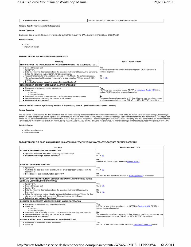
Pinpoint Test M: The Tachometer Is Inoperative
Normal Operation
Engine rpm data is provided to the instrument cluster by the PCM through the CAN, circuits 3125 (RD/YE) and 3126 (TN/YE).
Possible Causes
� PCM
� instrument cluster
PINPOINT TEST M: THE TACHOMETER IS INOPERATIVE
Pinpoint Test N: The Door Ajar Warning Indicator Is Inoperative (Chime Is Operative)/Does Not Operate Correctly
Normal Operation
The instrument cluster receives the door ajar status from the vehicle security module over the UBP communication network, circuit 693 (OG). When any of the doors are ajar, the door ajar switch will close, completing a ground signal to the vehicle security module. The vehicle security module receives the door ajar status from the hardwired door ajar switches. The liftgate ajar switch input is hardwired to the vehicle security module in series through circuit 700 (WH/VT) and the liftgate glass ajar switch, circuit 1351 (TN). The door ajar switches are hardwired to the vehicle security module through circuit 761 (GY/RD) (RF), 760 (PK/LB) (RR), 759 (LG/YE) (LR), and 765 (YE/BK) (LF). All of the door ajar switches are grounded through circuit 1205 (BK).
Possible Causes
� vehicle security module
� instrument cluster
PINPOINT TEST N: THE DOOR AJAR WARNING INDICATOR IS INOPERATIVE (CHIME IS OPERATIVE)/DOES NOT OPERATE CORRECTLY
� Is the concern still present? corroded connector. CLEAR the DTCs. REPEAT the self-test.
Test Step Result / Action to Take
M1 CARRY OUT THE TACHOMETER ACTIVE COMMAND USING THE DIAGNOSTIC TOOL
� Connect the scan tool. � Ignition ON. � Enter the following diagnostic mode on the scan tool: Instrument Cluster Active Command. � Select the instrument cluster tachometer active command. � Trigger the tachometer and scroll in increments of 10%. Monitor the tachometer gauge.
The tachometer should increase in increments of approximately 700 rpm for each 10% change.
� Does the tachometer gauge increase within specifications?
Yes REFER to Powertrain Control/Emissions Diagnosis (PC/ED) manual to continue diagnosis. No GO to M2.
M2 CHECK FOR CORRECT INSTRUMENT CLUSTER OPERATION
� Disconnect all instrument cluster connectors. � Check for:
� corrosion � pushed-out pins
� Connect all instrument cluster connectors and make sure they seat correctly. � Operate the system and verify the concern is still present. � Is the concern still present?
Yes INSTALL a new instrument cluster. REFER to Instrument Cluster (IC) in this section. TEST the system for normal operation. No The system is operating correctly at this time. Concern may have been caused by a loose or corroded connector. CLEAR the DTCs. REPEAT the self-test.
Test Step Result / Action to Take
N1 CHECK THE INTERIOR LAMPS OPERATION
� Open and close each door while monitoring the interior lamps. � Do the interior lamps operate correctly?
Yes GO to N2. No REPAIR the interior lamps. REFER to Section 417-02.
N2 VERIFY THE CHIME FUNCTION
� Ignition ON. � Verify that the door ajar chime sounds with the driver door open and stops with the
door closed. � Does the door ajar chime function correctly?
Yes GO to N3. No REPAIR the door ajar chime. REFER to Warning Devices in this section.
N3 CARRY OUT THE INSTRUMENT CLUSTER INDICATOR LAMP CONTROL ACTIVE COMMAND USING THE DIAGNOSTIC TOOL
� Ignition OFF. � Connect the scan tool. � Ignition ON. � Enter the following diagnostic mode on the scan tool: Instrument Cluster Active
Command. � Select the instrument cluster indicator lamp control active command. Trigger the door
ajar warning indicator active command. Observe the door ajar indicator. � Is the door ajar indicator illuminated?
Yes GO to N4. No GO to N5.
N4 CHECK FOR CORRECT VEHICLE SECURITY MODULE OPERATION
� Disconnect all vehicle security module connectors. � Check for:
� corrosion � pushed-out pins
� Connect all vehicle security module connectors and make sure they seat correctly. � Operate the system and verify the concern is still present. � Is the concern still present?
Yes INSTALL a new vehicle security module. REFER to Section 418-00. TEST the system for normal operation. No The system is operating correctly at this time. Concern may have been caused by a loose or corroded connector. CLEAR the DTCs. REPEAT the self-test.
N5 CHECK FOR CORRECT INSTRUMENT CLUSTER OPERATION
� Disconnect all instrument cluster connectors. � Check for:
Yes INSTALL a new instrument cluster. REFER to Instrument Cluster (IC) in this
Page 14 of 302004 Explorer/Mountaineer Workshop Manual
6/3/2011http://www.fordtechservice.dealerconnection.com/pubs/content/~WS4N/~MUS~LEN/20/S4...

Pinpoint Test O: The Safety Belt Warning Indicator Is Inoperative (Chime Is Operative)/Does Not Operate Correctly
Normal Operation
The safety belt warning indicator is controlled by the instrument cluster based upon the safety belt status received from the RCM. When the safety belt is unbuckled, the safety belt switch closes, providing a ground signal to the RCM through circuit 85 (BN/LB). When the safety belt is buckled, the safety belt switch opens, removing the ground path to the RCM. The RCM, monitoring the safety belt status, provides a ground to the instrument cluster through circuit 1390 (DB) when the safety belt switch is closed (unbuckled).
Possible Causes
� circuit 1390 (DB) open, short to ground or short to power
� RCM
� instrument cluster
PINPOINT TEST O: THE SAFETY BELT WARNING INDICATOR IS INOPERATIVE (CHIME IS OPERATIVE)/DOES NOT OPERATE CORRECTLY
� corrosion � pushed-out pins
� Connect all instrument cluster connectors and make sure they seat correctly. � Operate the system and verify the concern is still present. � Is the concern still present?
section. TEST the system for normal operation. No The system is operating correctly at this time. Concern may have been caused by a loose or corroded connector. CLEAR the DTCs. REPEAT the self-test.
Test Step Result / Action to Take
O1 CHECK THE SAFETY BELT WARNING INDICATOR OPERATION
� Deactivate the restraint control supplemental air bag system. Refer to Section 501-20B. � Ignition OFF. � Disconnect: RCM C310a. � Connect a fused (10A) jumper wire between the RCM C310a-22, circuit 1390 (DB), harness side and ground.
� Observe the safety belt warning indicator with the jumper wire connected and disconnected. � Ignition ON. � Does the safety belt warning indicator lamp illuminate with the jumper wire connected and turn off when
disconnected?
Yes GO to O5. No GO to O2.
O2 CHECK CIRCUIT 1390 (DB) FOR AN OPEN OR SHORT TO GROUND
� Ignition OFF. � Disconnect: Instrument Cluster C220a. � Measure the resistance between the instrument cluster C220a-13, circuit 1390 (DB), harness side and the restraint
control module C310a-22, circuit 1390 (DB), harness side; and between the instrument cluster C220a-13, circuit 1390 (DB), harness side and ground.
� Is the resistance less than 5 ohms between the instrument cluster and the restraint control module; and
greater than 10,000 ohms between the instrument cluster and ground?
Yes GO to O3. No REPAIR the circuit. TEST the system for normal operation.
O3 CHECK CIRCUIT 1390 (DB) FOR A SHORT TO POWER
� Ignition ON. � Measure the voltage between the instrument cluster C220a-13, circuit 1390 (DB), harness side and ground.
� Is any voltage present?
Yes REPAIR the circuit. TEST the system for normal operation. No GO to O4.
O4 CHECK FOR CORRECT INSTRUMENT CLUSTER OPERATION
� Disconnect all instrument cluster connectors. Yes
Page 15 of 302004 Explorer/Mountaineer Workshop Manual
6/3/2011http://www.fordtechservice.dealerconnection.com/pubs/content/~WS4N/~MUS~LEN/20/S4...

Pinpoint Test P: The Check Fuel Cap Indicator Is Never On
Normal Operation
The PCM monitors the fuel tank evaporative system for significant leaks that occur following refueling of the vehicle. If a fuel tank pressure change greater than a minus 23.7 kPa (7 inHg) of vacuum within 30 seconds after refueling has occurred, or there is excessive purge (fuel vapor) flow greater than 454 g (0.06 lb) per minute, the PCM will set DTC P0457 and send a message to the instrument cluster over the CAN communication network, circuits 3125 (RD/YE) and 3126 (TN/YE), to turn on the CHECK FUEL CAP indicator.
Possible Causes
� fuel tank evaporative system
� PCM
� instrument cluster
PINPOINT TEST P: THE CHECK FUEL CAP INDICATOR IS NEVER ON
Pinpoint Test Q: The Anti-Lock Brake System (ABS) Warning Indicator Is Never On
Normal Operation
ABS data is transmitted to the instrument cluster through the CAN, circuits 3125 (RD/YE) and 3126 (TN/YE).
Possible Causes
� ABS module
� instrument cluster
PINPOINT TEST Q: THE ANTI-LOCK BRAKE SYSTEM (ABS) WARNING INDICATOR IS NEVER ON
� Check for: � corrosion � pushed-out pins
� Connect all instrument cluster connectors and make sure they seat correctly. � Operate the system and verify the concern is still present. � Is the concern still present?
INSTALL a new instrument cluster. REFER to Instrument Cluster (IC) in this section. TEST the system for normal operation. No The system is operating correctly at this time. Concern may have been caused by a loose or corroded connector. CLEAR the DTCs. TEST the system for normal operation.
O5 CHECK FOR CORRECT RCM OPERATION
� Disconnect all RCM connectors. � Check for:
� corrosion � pushed-out pins
� Connect all RCM connectors and make sure they seat correctly. � Operate the system and verify the concern is still present. � Is the concern still present?
Yes INSTALL a new RCM. REFER to Section 501-20B. TEST the system for normal operation. No The system is operating correctly at this time. Concern may have been caused by a loose or corroded connector. CLEAR the DTCs. TEST the system for normal operation.
Test Step Result / Action to Take
P1 RETRIEVE AND RECORD DTCS FROM BOTH CONTINUOUS AND ON-DEMAND SELF-TESTS—PCM
� Connect the scan tool. � Ignition ON. � Enter the following diagnostic mode on the scan tool: Instrument Cluster
Continuous DTCs. � Retrieve and document the continuous DTCs. � Is DTC P0457 present?
Yes REFER to the Powertrain Control/Emissions Diagnosis (PC/ED) manual to continue diagnosis of DTC P0457. No GO to P2.
P2 CARRY OUT THE INSTRUMENT CLUSTER INDICATOR LAMP CONTROL ACTIVE COMMAND USING THE DIAGNOSTIC TOOL
� Enter the following diagnostic mode on the scan tool: Instrument Cluster Active Command.
� Select the instrument cluster indicator lamp control active command. Trigger the check cap indicator active command. Observe the CHECK FUEL CAP indicator.
� Is the CHECK FUEL CAP indicator illuminated?
Yes REFER to Powertrain Control/Emissions Diagnosis (PC/ED) manual to continue diagnosis. No GO to P3.
P3 CHECK FOR CORRECT INSTRUMENT CLUSTER OPERATION
� Disconnect all instrument cluster connectors. � Check for:
� corrosion � pushed-out pins
� Connect all instrument cluster connectors and make sure they seat correctly. � Operate the system and verify the concern is still present. � Is the concern still present?
Yes INSTALL a new instrument cluster. REFER to Instrument Cluster (IC) in this section. TEST the system for normal operation. No The system is operating correctly at this time. Concern may have been caused by a loose or corroded connector. CLEAR the DTCs. TEST the system for normal operation.
Test Step Result / Action to Take
Q1 CARRY OUT THE INSTRUMENT CLUSTER INDICATOR LAMP CONTROL ACTIVE COMMAND USING THE DIAGNOSTIC TOOL
� Connect the scan tool. � Ignition ON. � Enter the following diagnostic mode on the scan tool: Instrument Cluster Active
Command. � Select the instrument cluster indicator lamp control active command. Trigger the ABS
indicator active command. Observe the ABS warning indicator. � Is the ABS warning indicator illuminated?
Yes REFER to Section 206-09 to continue the diagnosis. No GO to Q2.
Page 16 of 302004 Explorer/Mountaineer Workshop Manual
6/3/2011http://www.fordtechservice.dealerconnection.com/pubs/content/~WS4N/~MUS~LEN/20/S4...

Pinpoint Test R: The Brake Warning Indicator Is Never/Always On
Normal Operation
The instrument cluster utilizes two separate strategies to operate the brake warning indicator. When the parking brake is applied, circuit 162 (LG/RD) to the instrument cluster is grounded by the parking brake switch through circuit 1203 (BK/LB). The instrument cluster receives the ground signal and turns on the brake warning indicator. When the brake fluid level is low or a base brake system concern is detected, the ABS module sends a signal to the instrument cluster over the CAN using circuits 3125 (RD/YE) and 3126 (TN/YE), to turn on the brake system warning indicator.
Possible Causes
� circuit 162 (LG/RD) open or shorted to power
� circuit 512 (TN/LG) short to ground
� circuit 977 (VT/WH) short to ground
� circuit 1203 (BK/LB) open
� circuit 1205 (BK) open
� parking brake switch
� brake fluid level switch
� ABS module
� instrument cluster
PINPOINT TEST R: THE BRAKE WARNING INDICATOR IS NEVER/ALWAYS ON
Q2 CHECK FOR CORRECT INSTRUMENT CLUSTER OPERATION
� Disconnect all instrument cluster connectors. � Check for:
� corrosion � pushed-out pins
� Connect all instrument cluster connectors and make sure they seat correctly. � Operate the system and verify the concern is still present. � Is the concern still present?
Yes INSTALL a new instrument cluster. REFER to Instrument Cluster (IC) in this section. TEST the system for normal operation. No The system is operating correctly at this time. Concern may have been caused by a loose or corroded connector. CLEAR the DTCs. REPEAT the self-test.
Test Step Result / Action to Take
R1 CARRY OUT THE INSTRUMENT CLUSTER INDICATOR LAMP CONTROL ACTIVE COMMAND USING THE DIAGNOSTIC TOOL
� Connect the scan tool. � Ignition ON. � Enter the following diagnostic mode on the scan tool: Instrument Cluster Active Command. � Select the instrument cluster indicator lamp control active command. Trigger the brake lamp active command on then off.
Observe the brake warning indicator. � Does the brake warning indicator illuminate when commanded on and turn off when commanded off?
Yes GO to R2. No GO to R11.
R2 CHECK THE ABS MODULE OPERATION
� Disconnect: Brake Fluid Level Switch C124. � Ignition ON. � Observe the brake warning indicator. � Ignition OFF. � Connect a fused (10A) jumper wire between the brake fluid level switch C124-3, circuit 977 (VT/WH), harness side and
ground.
� Ignition ON. � Observe the brake warning indicator. � Does the brake warning indicator illuminate with the brake fluid level switch disconnected and turn off when the
jumper wire is in place?
Yes GO to R3. No GO to R5.
R3 CHECK THE BRAKE FLUID LEVEL SWITCH
NOTE: Verify that the brake fluid level is full.
� Measure the resistances between the brake fluid level switch C124-1, circuit 1205 (BK), component side and the brake fluid level switch C124-3, circuit 977 (VT/WH), component side; and between the brake fluid level switch C124-2, circuit 512 (TN/LG), component side and the brake fluid level switch C124-3, circuit 977 (VT/WH), component side.
� Is the resistance greater than 10,000 ohms between the brake fluid level switch pin 1 and the brake fluid level switch
pin 3; and less than 5 ohms between the brake fluid level switch pin 2 and the brake fluid level switch pin 3?
Yes GO to R4. No INSTALL a new brake fluid level switch. TEST the system for normal operation.
R4 CHECK CIRCUIT 1205 (BK) FOR AN OPEN
Page 17 of 302004 Explorer/Mountaineer Workshop Manual
6/3/2011http://www.fordtechservice.dealerconnection.com/pubs/content/~WS4N/~MUS~LEN/20/S4...

� Measure the resistance between the brake fluid level switch C124-1, circuit 1205 (BK), harness side and ground.
� Is the resistance less than 5 ohms?
Yes GO to R7. No REPAIR the circuit. TEST the system for normal operation.
R5 CHECK CIRCUIT 977 (VT/WH) AND CIRCUIT 512 (TN/LG) FOR AN OPEN
� Ignition OFF. � Disconnect: ABS Module C155. � Measure the resistance between the ABS module C155-8, circuit 512 (TN/LG), harness side and the brake fluid level switch
C124-2, circuit 512 (TN/LG), harness side; and between the ABS module C155-9, circuit 977 (VT/WH), harness side and the brake fluid level switch C124-3, circuit 977 (VT/WH), harness side.
� Are the resistances less than 5 ohms?
Yes GO to R6. No REPAIR the circuit(s) in question. TEST the system for normal operation.
R6 CHECK CIRCUIT 977 (VT/WH) AND CIRCUIT 512 (TN/LG) FOR SHORT TO GROUND
� Measure the resistance between the ABS module C155-8, circuit 512 (TN/LG), harness side and ground; and between the ABS module C155-9, circuit 977 (VT/WH), harness side and ground.
� Are the resistances greater than 10,000 ohms?
Yes GO to R10. No REPAIR the circuit(s) in question. TEST the system for normal operation.
R7 CHECK THE PARKING BRAKE SWITCH
� Ignition OFF. � Disconnect: Parking Brake Switch C2015. � Measure the resistance between the parking brake switch C2015-1, circuit 162 (LG/RD), component side and the parking
brake switch C2015-2, circuit 1205 (BK), component side while engaging the parking brake.
� Is the resistance less than 5 ohms with the parking brake engaged and greater than 10,000 ohms with the parking
brake fully disengaged?
Yes GO to R8. No INSTALL a new parking brake switch. REFER to Section 206-00. TEST the system for normal operation.
R8 CHECK CIRCUIT 162 (LG/RD) FOR AN OPEN OR SHORT TO GROUND
� Ignition OFF. � Disconnect: Instrument Cluster C220a. � Disconnect: Daytime Running Lamp (DRL) Module C1030 (if equipped). � Measure the resistance between the instrument cluster C220a-14, circuit 162 (LG/RD), harness side and the parking brake
switch C2015-1, circuit 162 (LG/RD), harness side; and between the instrument cluster C220a-14, circuit 162 (LG/RD), harness side and ground.
Yes GO to R9. No REPAIR the circuit. TEST the system for normal operation.
Page 18 of 302004 Explorer/Mountaineer Workshop Manual
6/3/2011http://www.fordtechservice.dealerconnection.com/pubs/content/~WS4N/~MUS~LEN/20/S4...

Pinpoint Test S: The Service Engine Soon Indicator Is Never On
Normal Operation
The malfunction indicator lamp (MIL) is controlled by the instrument cluster utilizing data sent from the PCM over the CAN, using circuits 3125 (RD/YE) and 3126 (TN/YE).
Possible Causes
� PCM
� instrument cluster
PINPOINT TEST S: THE SERVICE ENGINE SOON INDICATOR IS NEVER ON
Pinpoint Test T: The Charging System Warning Indicator Is Never On
� Is the resistance less than 5 ohms between the instrument cluster and the parking brake switch; and greater than
10,000 ohms between the instrument cluster and ground?
R9 CHECK CIRCUIT 1203 (BK) FOR OPEN
� Measure the resistance between the parking brake switch C2015-2, circuit 1205 (BK), harness side and ground.
� Is the resistance less than 5 ohms?
Yes GO to R11. No REPAIR the circuit. TEST the system for normal operation.
R10 CHECK FOR CORRECT ABS MODULE OPERATION
� Disconnect all ABS module connectors. � Check for:
� corrosion � pushed-out pins
� Correct all ABS module connectors and make sure they seat correctly. � Operate the system and verify that the concern is still present. � Is the concern still present?
Yes INSTALL a new ABS module. REFER to Section 206-09. TEST the system for normal operation. No The system is operating correctly at this time. Concern may have been caused by a loose or corroded connector. TEST the system for normal operation.
R11 CHECK FOR CORRECT INSTRUMENT CLUSTER OPERATION
� Disconnect all instrument cluster connectors. � Check for:
� corrosion � pushed-out pins
� Correct all instrument cluster connectors and make sure they seat correctly. � Operate the system and verify that the concern is still present. � Is the concern still present?
Yes INSTALL a new instrument cluster. REFER to Instrument Cluster (IC) in this section. TEST the system for normal operation. No The system is operating correctly at this time. Concern may have been caused by a loose or corroded connector. TEST the system for normal operation.
Test Step Result / Action to Take
S1 CARRY OUT THE INSTRUMENT CLUSTER INDICATOR LAMP CONTROL ACTIVE COMMAND USING THE DIAGNOSTIC TOOL
� Connect the scan tool. � Ignition ON. � Enter the following diagnostic mode on the scan tool: Instrument Cluster Active Command. � Select the instrument cluster indicator lamp control active command. Trigger the service
engine malfunction indicator lamp (MIL) active command. Observe the SERVICE ENGINE SOON indicator.
� Is the SERVICE ENGINE SOON indicator illuminating?
Yes REFER to Powertrain Control/Emissions Diagnosis (PC/ED) manual to continue diagnosis. No GO to S2.
S2 CHECK FOR CORRECT INSTRUMENT CLUSTER OPERATION
� Disconnect all instrument cluster connectors. � Check for:
� corrosion � pushed-out pins
� Connect all instrument cluster connectors and make sure they seat correctly. � Operate the system and verify the concern is still present. � Is the concern still present?
Yes INSTALL a new instrument cluster. REFER to Instrument Cluster (IC) in this section. TEST the system for normal operation. No The system is operating correctly at this time. Concern may have been caused by a loose or corroded connector. CLEAR the DTCs. REPEAT the self-test.
Page 19 of 302004 Explorer/Mountaineer Workshop Manual
6/3/2011http://www.fordtechservice.dealerconnection.com/pubs/content/~WS4N/~MUS~LEN/20/S4...

Normal Operation
The charging system warning indicator is controlled by the instrument cluster based upon data received from the PCM over the CAN, using circuits 3125 (RD/YE) and 3126 (TN/YE). The instrument cluster will set DTC B1317 if the battery voltage, when in the START/RUN position, exceeds 16.5 volts DC ± 0.5 volts DC. The instrument cluster will set DTC B1318 if battery voltage, when in the START/RUN position, drops below 9 volts DC ± 0.5 volts DC.
Possible Causes
� charging system
� PCM
� instrument cluster
PINPOINT TEST T: THE CHARGING SYSTEM WARNING INDICATOR IS NEVER ON
Pinpoint Test U: The Air Bag Warning Indicator Is Never/Always On
Normal Operation
The instrument cluster air bag warning indicator is powered through the instrument cluster in the START/RUN position. The instrument cluster monitors the control circuit 608 (BK/YE) and provides a ground for the air bag indicator based upon the air bag signal received from the RCM. The instrument cluster will turn on the air bag warning indicator when it receives an open (no ground) from the RCM on control circuit 608 (BK/YE). The instrument cluster will turn off the air bag warning indicator if it receives a ground signal from the RCM on control circuit 608 (BK/YE).
Possible Causes
� circuit 608 (BK/YE) open or shorted to ground
� RCM
� instrument cluster
PINPOINT TEST U: THE AIR BAG WARNING INDICATOR IS NEVER/ALWAYS ON
Test Step Result / Action to Take
T1 CARRY OUT THE INSTRUMENT CLUSTER INDICATOR LAMP CONTROL ACTIVE COMMAND USING THE DIAGNOSTIC TOOL
� Connect the scan tool. � Ignition ON. � Enter the following diagnostic mode on the scan tool: Instrument Cluster Active
Command. � Select the instrument cluster indicator lamp active command. Trigger the charging
system warning indicator active command. Observe the charging system warning indicator.
� Is the charging system warning indicator illuminating?
Yes REFER to Powertrain Control/Emissions Diagnosis (PC/ED) manual to continue diagnosis. No GO to T2.
T2 CHECK FOR CORRECT INSTRUMENT CLUSTER OPERATION
� Disconnect all instrument cluster connectors. � Check for:
� corrosion � pushed-out pins
� Connect all instrument cluster connectors and make sure they seat correctly. � Operate the system and verify the concern is still present. � Is the concern still present?
Yes INSTALL a new instrument cluster. REFER to Instrument Cluster (IC) in this section. TEST the system for normal operation. No The system is operating correctly at this time. Concern may have been caused by a loose or corroded connector. CLEAR the DTCs. REPEAT the self-test.
Test Step Result / Action to Take
U1 CARRY OUT THE INSTRUMENT CLUSTER WARNING LAMPS AND CHIME ACTIVE COMMAND USING THE DIAGNOSTIC TOOL
� Connect the scan tool. � Ignition ON. � Enter the following diagnostic mode on the scan tool: Instrument Cluster Active Command. � Select the instrument cluster warning lamps and chime active command. Trigger the all lamps active
command ON then OFF. Observe the air bag warning indicator. � Does the air bag warning indicator turn on when commanded on and turn off when
commanded off?
Yes If the air bag indicator is never on, GO to U2 . If the air bag indicator is always on, GO to U4 . No GO to U6.
U2 CHECK CIRCUIT 608 (BK/YE)
� Deactivate the restraint control supplemental air bag system. Refer to Section 501-20B. � Ignition OFF. � Disconnect: RCM C310a. � Connect a fused (10A) jumper wire between the RCM C310a-19, circuit 608 (BK/YE), harness side
and ground.
� Ignition ON. � Does the air bag indicator lamp illuminate?
Yes GO to U7. No GO to U3.
U3 CHECK CIRCUIT 608 (BK/YE) FOR AN OPEN
� Ignition OFF. Yes GO to U6.
Page 20 of 302004 Explorer/Mountaineer Workshop Manual
6/3/2011http://www.fordtechservice.dealerconnection.com/pubs/content/~WS4N/~MUS~LEN/20/S4...

Pinpoint Test V: The High Beam Indicator Is Never On
Normal Operation
The high beam indicator bulb is powered through circuit 12 (LG/BK) when the multifunction switch is placed in the high beam position. The high beam indicator bulb is grounded through the instrument cluster bulb ground circuit 1205 (BK).
Possible Causes
� circuit 12 (LG/BK) open
� circuit 697 (BN) open
� circuit 1205 (BK) open
� multifunction switch
� instrument cluster
PINPOINT TEST V: THE HIGH BEAM INDICATOR IS NEVER ON
� Disconnect: Instrument Cluster C220b. � Measure the resistance between the instrument cluster C220b-3, circuit 608 (BK/YE), harness side
and the restraint control module C310a-19, circuit 608 (BK/YE), harness side.
� Is the resistance less than 5 ohms?
No REPAIR the circuit. TEST the system for normal operation.
U4 ISOLATE THE RCM
� Ignition OFF. � Deactivate the restraint control supplemental air bag system. Refer to Section 501-20B. � Disconnect: RCM C310a. � Observe the air bag warning indicator. � Ignition ON. � Does the air bag warning indicator illuminate?
Yes GO to U5. No REPAIR the supplemental restraint system. REFER to Section 501-20B.
U5 CHECK CIRCUIT 608 (BK/YE) FOR SHORT TO GROUND
� Ignition OFF. � Disconnect: Instrument Cluster C220b. � Measure the resistance between the instrument cluster C220b-3, circuit 608 (BK/YE), harness side
and ground.
� Is the resistance greater than 10,000 ohms?
Yes GO to U6. No REPAIR the circuit. TEST the system for normal operation.
U6 CHECK FOR CORRECT INSTRUMENT CLUSTER OPERATION
� Disconnect all instrument cluster connectors. � Check for:
� corrosion � pushed-out pins
� Connect all instrument cluster connectors and make sure they seat correctly. � Operate the system and verify the concern is still present. � Is the concern still present?
Yes INSTALL a new instrument cluster. REFER to Instrument Cluster (IC) in this section. TEST the system for normal operation. No The system is operating correctly at this time. Concern may have been caused by a loose or corroded connector. CLEAR the DTCs. REPEAT the self-test.
U7 CHECK FOR CORRECT RESTRAINT CONTROL MODULE (RCM) OPERATION
� Disconnect all RCM connectors. � Check for:
� corrosion � pushed-out pins
� Connect all RCM connectors and make sure they seat correctly. � Operate the system and verify the concern is still present. � Is the concern still present?
Yes INSTALL a new RCM. REFER to Section 501-20B. TEST the system for normal operation. No The system is operating correctly at this time. Concern may have been caused by a loose or corroded connector. CLEAR the DTCs. REPEAT the self-test.
Test Step Result / Action to Take
V1 VERIFY HIGH BEAM OPERATION
� Verify the high beam headlamps operation. � Do the high beam headlamps operate correctly?
Yes GO to V2. No REPAIR the high beams. REFER to Section 417-01.
Page 21 of 302004 Explorer/Mountaineer Workshop Manual
6/3/2011http://www.fordtechservice.dealerconnection.com/pubs/content/~WS4N/~MUS~LEN/20/S4...

Pinpoint Test W: The LH Turn Indicator Is Never On
Normal Operation
The LH turn indicator bulb is powered through circuit 1393 (LB/RD) when the multifunction switch is placed in the LH turn signal position. The LH turn indicator bulb is grounded through the instrument cluster bulb ground circuit 1205 (BK).
Possible Causes
� circuit 1393 (LB/RD) open
� circuit 1205 (BK) open
� multifunction switch
� instrument cluster
PINPOINT TEST W: THE LH TURN INDICATOR IS NEVER ON
V2 CHECK CIRCUITS 697 (BN) AND 12 (LG/BK) FOR AN OPEN
� Disconnect: Instrument Cluster C220b. � NOTE: Headlamps must be on for this test. � Place the multifunction switch in the high beam position. � Measure the voltage between the instrument cluster C220b-13, circuit 12 (LG/BK),
harness side and ground.
� Is the voltage greater than 10 volts?
Yes GO to V3. No REPAIR the circuit(s) in question. TEST the system for normal operation.
V3 CHECK CIRCUIT 1205 (BK) FOR AN OPEN
� Measure the resistance between the instrument cluster C220b-11, circuit 1205 (BK), harness side and ground.
� Is the resistance less than 5 ohms?
Yes GO to V4. No REPAIR the circuit. TEST the system for normal operation.
V4 CHECK FOR CORRECT INSTRUMENT CLUSTER OPERATION
� Disconnect all instrument cluster connectors. � Check for:
� corrosion � pushed-out pins
� Connect all instrument cluster connectors and make sure they seat correctly. � Operate the system and verify the concern is still present. � Is the concern still present?
Yes INSTALL a new instrument cluster. REFER to Instrument Cluster (IC) in this section. TEST the system for normal operation. No The system is operating correctly at this time. Concern may have been caused by a loose or corroded connector. CLEAR the DTCs. REPEAT the self-test.
Test Step Result / Action to Take
W1 VERIFY TURN SIGNAL OPERATION
� Verify the turn signal operation. � Do the turn signals operate correctly?
Yes GO to W2. No REPAIR the turn signals. REFER to Section 417-01.
W2 CHECK CIRCUIT 1393 (LB/RD) FOR VOLTAGE
� Disconnect: Instrument Cluster C220b. � Ignition ON. � Place the multifunction switch in the LH turn signal position. � Measure the voltage between the instrument cluster C220b-1, circuit 1393 (LB/RD),
harness side and ground.
Yes GO to W3. No REPAIR the circuit. TEST the system for normal operation.
Page 22 of 302004 Explorer/Mountaineer Workshop Manual
6/3/2011http://www.fordtechservice.dealerconnection.com/pubs/content/~WS4N/~MUS~LEN/20/S4...

Pinpoint Test X: The RH Turn Indicator Is Never On
Normal Operation
The RH turn indicator bulb is powered through circuit 1392 (LG/OG) when the multifunction switch is placed in the RH turn signal position. The RH turn indicator bulb is grounded through the instrument cluster bulb ground circuit 1205 (BK).
Possible Causes
� circuit 1205 (BK) open
� circuit 1392 (LG/OG) open
� multifunction switch
� instrument cluster
PINPOINT TEST X: THE RH TURN INDICATOR IS NEVER ON
� Does the voltage fluctuate between 0 and greater than 10 volts?
W3 CHECK CIRCUIT 1205 (BK) FOR AN OPEN
� Ignition OFF. � Disconnect: Instrument Cluster C220a. � Measure the resistance between the instrument cluster C220b-11, circuit 1205 (BK),
harness side and ground.
� Is the resistance less than 5 ohms?
Yes GO to W4. No REPAIR the circuit. TEST the system for normal operation.
W4 CHECK FOR CORRECT INSTRUMENT CLUSTER OPERATION
� Disconnect all instrument cluster connectors. � Check for:
� corrosion � pushed-out pins
� Connect all instrument cluster connectors and make sure they seat correctly. � Operate the system and verify the concern is still present. � Is the concern still present?
Yes INSTALL a new instrument cluster. REFER to Instrument Cluster (IC) in this section. TEST the system for normal operation. No The system is operating correctly at this time. Concern may have been caused by a loose or corroded connector. CLEAR the DTCs. REPEAT the self-test.
Test Step Result / Action to Take
X1 VERIFY THE TURN SIGNAL OPERATION
� Verify the turn signal operation. � Do the turn signals operate correctly?
Yes GO to X2. No REPAIR the turn signals. REFER to Section 417-01.
X2 CHECK CIRCUIT 1392 (LG/OG) FOR VOLTAGE
� Disconnect: Instrument Cluster C220a. � Ignition ON. � Place the multifunction switch in the RH turn signal position. � Measure the voltage between the instrument cluster C220a-16, circuit 1392
(LG/OG), harness side and ground.
� Does the voltage fluctuate between 0 and greater than 10 volts?
Yes GO to X3. No REPAIR the circuit. TEST the system for normal operation.
X3 CHECK CIRCUIT 1205 (BK) FOR AN OPEN
Page 23 of 302004 Explorer/Mountaineer Workshop Manual
6/3/2011http://www.fordtechservice.dealerconnection.com/pubs/content/~WS4N/~MUS~LEN/20/S4...

Pinpoint Test Y: The 4X4 HIGH/AWD LOCK Indicator Is Never/Always On
Normal Operation
The 4X4 high/AWD indicator status is transmitted to the instrument cluster from the four-wheel drive control module through the CAN circuits. For additional information on the CAN circuits, refer to Section 418-00.
Possible Causes
� four-wheel drive module
� instrument cluster
PINPOINT TEST Y: THE 4X4 HIGH/AWD LOCK INDICATOR IS NEVER/ALWAYS ON
Pinpoint Test Z: The 4X4 LOW Indicator Is Never/Always On
Normal Operation
The 4X4 low indicator status is transmitted to the instrument cluster from the four-wheel drive control module through the CAN circuits. For additional information on the CAN circuits, refer to Section 418-00.
Possible Causes
� four-wheel drive module
� Ignition OFF. � Disconnect: Instrument Cluster C220a. � Measure the resistance between the instrument cluster C220b-11, circuit 1205 (BK),
harness side and ground.
� Is the resistance less than 5 ohms?
Yes GO to X4. No REPAIR the circuit. TEST the system for normal operation.
X4 CHECK FOR CORRECT INSTRUMENT CLUSTER OPERATION
� Disconnect all instrument cluster connectors. � Check for:
� corrosion � pushed-out pins
� Connect all instrument cluster connectors and make sure they seat correctly. � Operate the system and verify the concern is still present. � Is the concern still present?
Yes INSTALL a new instrument cluster. REFER to Instrument Cluster (IC) in this section. TEST the system for normal operation. No The system is operating correctly at this time. Concern may have been caused by a loose or corroded connector. CLEAR the DTCs. REPEAT the self-test.
Test Step Result / Action to Take
Y1 VERIFY THE FOUR-WHEEL DRIVE OPERATION
� Test drive the vehicle and verify that the vehicle is in two-wheel drive when the 4x4 HIGH or AWD (if equipped) is switched off and that the four-wheel drive high operates when switched to the 4x4 HIGH or AWD (if equipped) range.
� Does the 4x4 HIGH or AWD (if equipped) range operate correctly?
Yes GO to Y2. No REPAIR the four-wheel drive. REFER to Section 308-07.
Y2 CARRY OUT THE INSTRUMENT CLUSTER FOUR-WHEEL DRIVE TRANSFER CASE CONTROL ACTIVE COMMAND USING THE DIAGNOSTIC TOOL
� Ignition OFF. � Connect the scan tool. � Ignition ON. � Enter the following diagnostic mode on the scan tool: Instrument Cluster Active Command. � Select the instrument cluster four-wheel drive transfer case control active command. Trigger the
four-wheel drive high active command ON and OFF. Observe the 4x4 HIGH or AWD LOCK (if equipped) indicator.
� Does the 4x4 HIGH or AWD LOCK (if equipped) indicator illuminate when commanded on and turn off when commanded off?
Yes GO to Y3. No GO to Y4.
Y3 CHECK FOR CORRECT FOUR-WHEEL DRIVE MODULE OPERATION
� Disconnect all four-wheel drive module connectors. � Check for:
� corrosion � pushed-out pins
� Connect all four-wheel drive module connectors and make sure they seat correctly. � Operate the system and verify the concern is still present. � Is the concern still present?
Yes INSTALL a new four-wheel drive module. REFER to Section 308-07. TEST the system for normal operation. No The system is operating correctly at this time. Concern may have been caused by a loose or corroded connector. CLEAR the DTCs. TEST the system for normal operation.
Y4 CHECK FOR CORRECT INSTRUMENT CLUSTER OPERATION
� Disconnect all instrument cluster connectors. � Check for:
� corrosion � pushed-out pins
� Connect all instrument cluster connectors and make sure they seat correctly. � Operate the system and verify the concern is still present. � Is the concern still present?
Yes INSTALL a new instrument cluster. REFER to Instrument Cluster (IC) in this section. TEST the system for normal operation. No The system is operating correctly at this time. Concern may have been caused by a loose or corroded connector. CLEAR the DTCs. TEST the system for normal operation.
Page 24 of 302004 Explorer/Mountaineer Workshop Manual
6/3/2011http://www.fordtechservice.dealerconnection.com/pubs/content/~WS4N/~MUS~LEN/20/S4...

� instrument cluster
PINPOINT TEST Z: THE 4X4 LOW INDICATOR IS NEVER/ALWAYS ON
Pinpoint Test AA: The Speed Control Indicator Is Never/Always On
Normal Operation
The speed control status information is sent to the instrument cluster from the PCM over the CAN, using circuits 3125 (RD/YE) and 3126 (TN/YE).
Possible Causes
� PCM
� instrument cluster
PINPOINT TEST AA: THE SPEED CONTROL INDICATOR IS NEVER/ALWAYS ON
Test Step Result / Action to Take
Z1 VERIFY THE FOUR-WHEEL DRIVE OPERATION
� Test drive the vehicle and verify that the vehicle is in two-wheel drive when the 4x4 LOW is switched off and that the four-wheel drive low operates when switched to the 4x4 LOW range.
� Does the 4x4 LOW range operate correctly?
Yes GO to Z2. No REPAIR the four-wheel drive. REFER to Section 308-07.
Z2 CARRY OUT THE INSTRUMENT CLUSTER FOUR-WHEEL DRIVE TRANSFER CASE CONTROL ACTIVE COMMAND USING THE DIAGNOSTIC TOOL
� Ignition OFF. � Connect the scan tool. � Ignition ON. � Enter the following diagnostic mode on the scan tool: Instrument Cluster Active
Command. � Select the instrument cluster four-wheel drive transfer case control active command.
Trigger the four-wheel drive low active command ON and OFF. Observe the 4x4 LOW indicator.
� Does the 4x4 LOW indicator illuminate when commanded on and turn off when commanded off?
Yes GO to Z3. No GO to Z4.
Z3 CHECK FOR CORRECT FOUR-WHEEL DRIVE MODULE OPERATION
� Disconnect all four-wheel drive module connectors. � Check for:
� corrosion � pushed-out pins
� Connect all four-wheel drive module connectors and make sure they seat correctly. � Operate the system and verify the concern is still present. � Is the concern still present?
Yes INSTALL a new four-wheel drive module. REFER to Section 308-07. TEST the system for normal operation. No The system is operating correctly at this time. Concern may have been caused by a loose or corroded connector. CLEAR the DTCs. TEST the system for normal operation.
Z4 CHECK FOR CORRECT INSTRUMENT CLUSTER OPERATION
� Disconnect all instrument cluster connectors. � Check for:
� corrosion � pushed-out pins
� Connect all instrument cluster connectors and make sure they seat correctly. � Operate the system and verify the concern is still present. � Is the concern still present?
Yes INSTALL a new instrument cluster. REFER to Instrument Cluster (IC) in this section. TEST the system for normal operation. No The system is operating correctly at this time. Concern may have been caused by a loose or corroded connector. CLEAR the DTCs. TEST the system for normal operation.
Test Step Result / Action to Take
AA1 CHECK THE SPEED CONTROL OPERATION
� Test drive the vehicle and operate the speed control. � Does the speed control operate correctly?
Yes GO to AA2. No REPAIR the speed control. REFER to Section 310-03.
AA2 CARRY OUT THE INSTRUMENT CLUSTER SELF-TEST
� Ignition ON. � Carry out the instrument cluster self-test and observe the speed control
indicator. Refer to the Instrument Cluster Self-Test Mode in this section. � Does the speed control indicator illuminate during the self-test mode and
turn off when not in the self-test mode?
Yes GO to AA3. No GO to AA4.
AA3 CHECK FOR CORRECT PCM OPERATION
� Disconnect all PCM connectors. � Check for:
� corrosion � pushed-out pins
� Connect all PCM connectors and make sure they seat correctly. � Operate the system and verify the concern is still present. � Is the concern still present?
Yes INSTALL a new PCM. REFER to Section 303-04A (4.0L) or Section 303-04B (4.6L). TEST the system for normal operation. No The system is operating correctly at this time. Concern may have been caused by a loose or corroded connector. CLEAR the DTCs. TEST the system for normal operation.
AA4 CHECK FOR CORRECT INSTRUMENT CLUSTER OPERATION
� Disconnect all instrument cluster connectors. � Check for:
� corrosion � pushed-out pins
� Connect all instrument cluster connectors and make sure they seat correctly. � Operate the system and verify the concern is still present. � Is the concern still present?
Yes INSTALL a new instrument cluster. REFER to Instrument Cluster (IC) in this section. TEST the system for normal operation. No The system is operating correctly at this time. Concern may have been caused by a loose or corroded connector. CLEAR the DTCs. TEST the system for normal operation.
Page 25 of 302004 Explorer/Mountaineer Workshop Manual
6/3/2011http://www.fordtechservice.dealerconnection.com/pubs/content/~WS4N/~MUS~LEN/20/S4...

Pinpoint Test AB: The Check Gauge Warning Indicator Is Never/Always On
Normal Operation
The check gauge warning indicator status information is transmitted to the instrument cluster over the CAN, using circuits 3125 (RD/YE) and 3126 (TN/YE). The PCM will send a signal to the instrument cluster to turn on the check gauge warning indicator if the engine oil pressure drops below approximately 42 kPa (6 psi), the engine temperature exceeds approximately 118° C (244° F), or if the fuel level drops below approximately 15 percent of fuel system capacity (base cluster only).
Possible Causes
� PCM
� instrument cluster
PINPOINT TEST AB: THE CHECK GAUGE WARNING INDICATOR IS NEVER/ALWAYS ON
Pinpoint Test AC: The O/D OFF Indicator Is Never/Always On
Normal Operation
The overdrive (O/D) off function is controlled by the O/D off switch located on the shifter assembly. When the transmission is placed in the O/D off position, the O/D off switch provides a ground to the PCM through circuit 224 (TN/WH). The O/D off status is then transmitted to the instrument cluster from the PCM over the CAN, using circuits 3125 (RD/YE) and 3126 (TN/YE). For additional information about the overdrive function, refer to Section 307-01.
Possible Causes
� PCM
� instrument cluster
PINPOINT TEST AC: THE O/D OFF INDICATOR IS NEVER/ALWAYS ON
Pinpoint Test AD: The Traction Control Indicator Is Never/Always On
Normal Operation
The instrument cluster receives the traction control status from the anti-lock brake system/traction control/integrated vehicle dynamics (ABS/TC/IVD) module through the CAN, using circuits 3125 (RD/YE) and 3126 (TN/YE).
Possible Causes
Test Step Result / Action to Take
AB1 CARRY OUT THE INSTRUMENT CLUSTER INDICATOR LAMP CONTROL ACTIVE COMMAND USING THE DIAGNOSTIC TOOL
� Ignition OFF. � Connect the scan tool. � Ignition ON. � Enter the following diagnostic mode on the scan tool: Instrument Cluster Active Command. � Select the instrument cluster indicator lamp control active command. Trigger the check
gauges indicator active command ON then OFF. Observe the check gauge indicator. � Does the check gauge indicator turn on when commanded on and turn off when
commanded off?
Yes GO to AB2. No GO to AB3.
AB2 CHECK THE GAUGES
� Start the engine. � Verify the fuel gauge, voltmeter and the oil pressure gauge operation. � Are the gauges operating correctly?
Yes GO to AB3. No GO to Symptom Chart.
AB3 CHECK FOR CORRECT INSTRUMENT CLUSTER OPERATION
� Disconnect all instrument cluster connectors. � Check for:
� corrosion � pushed-out pins
� Connect all instrument cluster connectors and make sure they seat correctly. � Operate the system and verify the concern is still present. � Is the concern still present?
Yes INSTALL a new instrument cluster. REFER to Instrument Cluster (IC) in this section. TEST the system for normal operation. No The system is operating correctly at this time. Concern may have been caused by a loose or corroded connector. CLEAR the DTCs. REPEAT the self-test.
Test Step Result / Action to Take
AC1 CARRY OUT THE INSTRUMENT CLUSTER WARNING LAMPS AND CHIME ACTIVE COMMAND USING THE DIAGNOSTIC TOOL
� Connect the scan tool. � Ignition ON. � Enter the following diagnostic mode on the scan tool: Instrument Cluster Active
Command. � Select the instrument cluster warning lamps and chime active command. Trigger the
all warning lamps active command ON and then OFF. Observe the O/D OFF indicator.
� Does the O/D OFF indicator illuminate when commanded on and turn off when commanded off?
Yes REFER to Powertrain Control/Emissions Diagnosis (PC/ED) manual to continue the diagnosis. No GO to AC2.
AC2 CHECK FOR CORRECT INSTRUMENT CLUSTER OPERATION
� Disconnect all instrument cluster connectors. � Check for:
� corrosion � pushed-out pins
� Connect all instrument cluster connectors and make sure they seat correctly. � Operate the system and verify the concern is still present. � Is the concern still present?
Yes INSTALL a new instrument cluster. REFER to Instrument Cluster (IC) in this section. TEST the system for normal operation. No The system is operating correctly at this time. Concern may have been caused by a loose or corroded connector. CLEAR the DTCs. TEST the system for normal operation.
Page 26 of 302004 Explorer/Mountaineer Workshop Manual
6/3/2011http://www.fordtechservice.dealerconnection.com/pubs/content/~WS4N/~MUS~LEN/20/S4...

� ABS/TC/IVD module
� instrument cluster
PINPOINT TEST AD: THE TRACTION CONTROL INDICATOR IS ALWAYS/NEVER ON
Pinpoint Test AE: The Integrated Circuit Display Is Inoperative
Normal Operation
The integrated circuit display contains the odometer, trip odometer, outside air temperature and compass display on base clusters and the message center display on message center clusters. The compass module is hardwired to the instrument cluster through circuits 702 (WH/BK) and 703 (WH/OG), the outside air temperature sensor is hardwired to the instrument cluster through circuits 233 (DB/YE) and 234 (DB/WH). The odometer and trip odometer information is transmitted from the powertrain control module (PCM) through the CAN circuits to the instrument cluster. For additional information on the message center, refer to Information And Message Center in this section.
Possible Causes
� 233 (DB/YE) open or short to ground
� 234 (DB/WH) open or short to ground
� outside air temperature sensor
� instrument cluster
PINPOINT TEST AE: THE INTEGRATED CIRCUIT DISPLAY IS INOPERATIVE
Test Step Result / Action to Take
AD1 CARRY OUT THE INSTRUMENT CLUSTER INDICATOR LAMP ACTIVE COMMAND USING THE DIAGNOSTIC TOOL
� Ignition ON. � Enter the following diagnostic mode on the scan tool: Instrument Cluster Active
Command. � Select the instrument cluster indicator lamp active command. Trigger the traction assist
active indicator lamp active command ON and then OFF. Observe the traction control indicator.
� Does the traction control indicator illuminate when commanded on and turn off when commanded off?
Yes REFER to Section 206-09 to continue the diagnosis. No GO to AD2.
AD2 CHECK FOR CORRECT INSTRUMENT CLUSTER OPERATION
� Disconnect all instrument cluster connectors. � Check for:
� corrosion � pushed-out pins
� Connect all instrument cluster connectors and make sure they seat correctly. � Operate the system and verify the concern is still present. � Is the concern still present?
Yes INSTALL a new instrument cluster. REFER to Instrument Cluster (IC) in this section. TEST the system for normal operation. No The system is operating correctly at this time. Concern may have been caused by a loose or corroded connector. CLEAR the DTCs. TEST the system for normal operation.
Test Step Result / Action to Take
AE1 RETRIEVE AND RECORD DTCS FROM BOTH CONTINUOUS AND ON-DEMAND SELF-TESTS—INSTRUMENT CLUSTER
� Connect the scan tool. � Ignition ON. � Enter the following diagnostic mode on the scan tool: Instrument Cluster Continuous DTCs. � Retrieve and document the continuous DTCs. � Are DTCs B1255, B1257, B2143 or U2013 retrieved?
Yes If DTC B2143 is present, GO to AE7 . If DTC B1255 or B1257 are present, GO to AE4 . No If DTC U2013 is present, GO to AE2 .
AE2 VERIFY THE INTEGRATED CIRCUIT DISPLAY OPERATION
� Ignition ON. � Monitor the compass, air temperature and odometer/trip odometer functions of the integrated circuit display. � Does the integrated circuit display operate correctly?
Yes The system is operating correctly at this time. No If the compass is inoperative, GO to Pinpoint Test AL. If the odometer/trip odometer are inoperative, GO to AE3 . For base clusters, if the air temperature display is inoperative, GO to AE4 .
AE3 VERIFY THE SPEEDOMETER OPERATION
� Operate the vehicle and verify the speedometer operation. � Does the speedometer operate correctly?
Yes GO to AE4. No GO to Pinpoint Test K.
AE4 CHECK THE AMBIENT AIR TEMPERATURE SENSOR FUNCTION
� Disconnect: Ambient Air Temperature Sensor C132. � Measure the resistance between the ambient air temperature sensor C132-1, circuit 234 (DB/WH), component side
and the ambient air temperature sensor C132-2, circuit 233 (DB/YE), component side at ambient temperature of 18°-29°C (65°-85°F).
Yes GO to AE5. No INSTALL a new ambient air temperature sensor. TEST the system for normal operation.
Page 27 of 302004 Explorer/Mountaineer Workshop Manual
6/3/2011http://www.fordtechservice.dealerconnection.com/pubs/content/~WS4N/~MUS~LEN/20/S4...
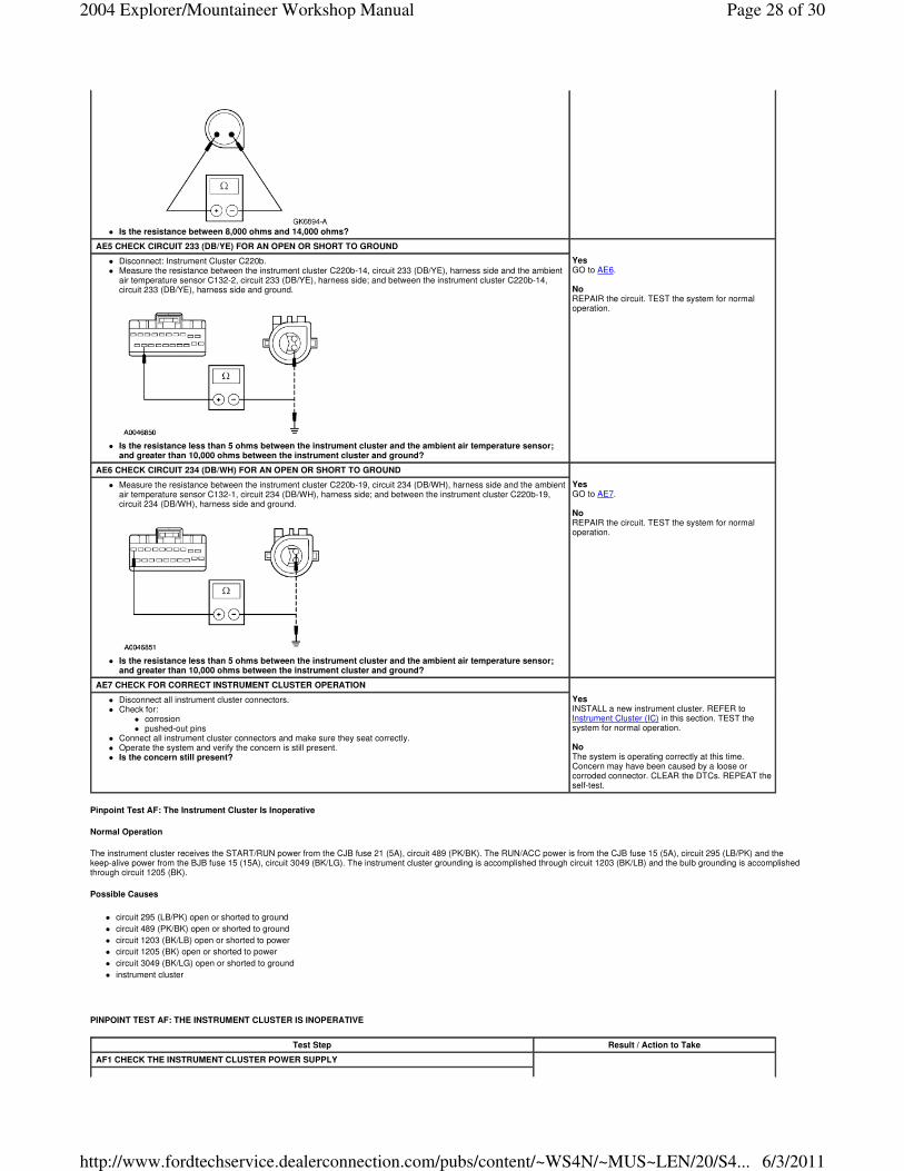
Pinpoint Test AF: The Instrument Cluster Is Inoperative
Normal Operation
The instrument cluster receives the START/RUN power from the CJB fuse 21 (5A), circuit 489 (PK/BK). The RUN/ACC power is from the CJB fuse 15 (5A), circuit 295 (LB/PK) and the keep-alive power from the BJB fuse 15 (15A), circuit 3049 (BK/LG). The instrument cluster grounding is accomplished through circuit 1203 (BK/LB) and the bulb grounding is accomplished through circuit 1205 (BK).
Possible Causes
� circuit 295 (LB/PK) open or shorted to ground
� circuit 489 (PK/BK) open or shorted to ground
� circuit 1203 (BK/LB) open or shorted to power
� circuit 1205 (BK) open or shorted to power
� circuit 3049 (BK/LG) open or shorted to ground
� instrument cluster
PINPOINT TEST AF: THE INSTRUMENT CLUSTER IS INOPERATIVE
� Is the resistance between 8,000 ohms and 14,000 ohms?
AE5 CHECK CIRCUIT 233 (DB/YE) FOR AN OPEN OR SHORT TO GROUND
� Disconnect: Instrument Cluster C220b. � Measure the resistance between the instrument cluster C220b-14, circuit 233 (DB/YE), harness side and the ambient
air temperature sensor C132-2, circuit 233 (DB/YE), harness side; and between the instrument cluster C220b-14, circuit 233 (DB/YE), harness side and ground.
� Is the resistance less than 5 ohms between the instrument cluster and the ambient air temperature sensor;
and greater than 10,000 ohms between the instrument cluster and ground?
Yes GO to AE6. No REPAIR the circuit. TEST the system for normal operation.
AE6 CHECK CIRCUIT 234 (DB/WH) FOR AN OPEN OR SHORT TO GROUND
� Measure the resistance between the instrument cluster C220b-19, circuit 234 (DB/WH), harness side and the ambient air temperature sensor C132-1, circuit 234 (DB/WH), harness side; and between the instrument cluster C220b-19, circuit 234 (DB/WH), harness side and ground.
� Is the resistance less than 5 ohms between the instrument cluster and the ambient air temperature sensor;
and greater than 10,000 ohms between the instrument cluster and ground?
Yes GO to AE7. No REPAIR the circuit. TEST the system for normal operation.
AE7 CHECK FOR CORRECT INSTRUMENT CLUSTER OPERATION
� Disconnect all instrument cluster connectors. � Check for:
� corrosion � pushed-out pins
� Connect all instrument cluster connectors and make sure they seat correctly. � Operate the system and verify the concern is still present. � Is the concern still present?
Yes INSTALL a new instrument cluster. REFER to Instrument Cluster (IC) in this section. TEST the system for normal operation. No The system is operating correctly at this time. Concern may have been caused by a loose or corroded connector. CLEAR the DTCs. REPEAT the self-test.
Test Step Result / Action to Take
AF1 CHECK THE INSTRUMENT CLUSTER POWER SUPPLY
Page 28 of 302004 Explorer/Mountaineer Workshop Manual
6/3/2011http://www.fordtechservice.dealerconnection.com/pubs/content/~WS4N/~MUS~LEN/20/S4...

Pinpoint Test AG: The Low Tire Warning Indicator is Never On
Normal Operation
The tire pressure monitoring system module requires an operating voltage in a range between 10 and 17 volts. Voltage is supplied by circuit 1050 (LG/VT) (ignition feed) and circuit 1003 (GY/YE) (B+ voltage at all times). Ground is provided through circuit 1205 (BK).
Possible Causes
� circuit 1050 (LG/VT)
� circuit 1003 (GY/YE)
� circuit 1205 (BK)
� tire pressure monitoring system module
� instrument cluster
� Ignition OFF. � Disconnect: Instrument Cluster C220a and C220b. � Ignition ON. � Using the following table, measure the voltage between the instrument cluster, harness side and ground.
� Are the voltages greater than 10 volts?
Connector/Pin Circuit
C220b-18 295 (LB/PK)
C220a-1 3049 (BK/LG)
Yes GO to AF2. No REPAIR the circuit(s) in question. TEST the system for normal operation.
AF2 CHECK THE INSTRUMENT CLUSTER POWER SUPPLY
� Ignition ON. � Measure the voltage between the instrument cluster C220a-7, circuit 489 (PK/BK), harness side and ground.
� Is the voltage greater than 10 volts?
Yes GO to AF3. No REPAIR the circuit(s) in question. TEST the system for normal operation.
AF3 CHECK INSTRUMENT CLUSTER GROUND CIRCUITS 1205 (BK) AND 1203 (BK/LB)
� Ignition OFF. � Measure the resistance between the instrument cluster C220b-11, circuit 1205 (BK), harness side and
ground; and between the instrument cluster C220a-2, circuit 1203 (BK/LB), harness side and ground.
� Are the resistances less than 5 ohms?
Yes GO to AF4. No REPAIR the circuit(s) in question. TEST the system for normal operation.
AF4 CHECK FOR CORRECT INSTRUMENT CLUSTER OPERATION
� Disconnect all instrument cluster connectors. � Check for:
� corrosion � pushed-out pins
� Connect all instrument cluster connectors and make sure they seat correctly. � Operate the system and verify the concern is still present. � Is the concern still present?
Yes INSTALL a new instrument cluster. REFER to Instrument Cluster (IC) in this section. TEST the system for normal operation. No The system is operating correctly at this time. Concern may have been caused by a loose or corroded connector. CLEAR the DTCs. REPEAT the self-test.
Page 29 of 302004 Explorer/Mountaineer Workshop Manual
6/3/2011http://www.fordtechservice.dealerconnection.com/pubs/content/~WS4N/~MUS~LEN/20/S4...

PINPOINT TEST AG: THE LOW TIRE WARNING INDICATOR IS NEVER ON
Pinpoint Test AH: The Electronic Throttle Control Indicator is Never On
Normal Operation
The instrument cluster receives the electronic throttle control status from the powertrain control module (PCM) over the CAN, using circuits 3125 (RD/YE) and 3126 (TN/YE). When a system concern is detected, the PCM sends the instrument cluster a command signal to turn the electronic throttle control indicator ON.
Possible Causes
� PCM
� instrument cluster
PINPOINT TEST AH: THE ELECTRONIC THROTTLE CONTROL INDICATOR IS NEVER ON
Test Step Result / Action to Take
AG1 CARRY OUT THE INSTRUMENT CLUSTER INDICATOR LAMP CONTROL ACTIVE COMMAND USING THE DIAGNOSTIC TOOL
� Ignition OFF. � Connect the scan tool. � Ignition ON. � Enter the following diagnostic mode on the diagnostic tool: Instrument Cluster Active
Command. � Select the instrument cluster warning lamps and chime active command. Trigger the all
lamps active command ON then OFF. Observe the low tire warning indicator. � Does the low tire warning indicator turn on when commanded on and turn off when
commanded off?
Yes REFER to Section 204-00 to continue diagnosis of the low tire warning system. No GO to AG2.
AG2 CHECK FOR CORRECT INSTRUMENT CLUSTER OPERATION
� Disconnect all instrument cluster connectors. � Check for:
� corrosion � pushed-out pins
� Connect all instrument cluster connectors and make sure they seat correctly. � Operate the system and verify the concern is still present. � Is the concern still present?
Yes INSTALL a new instrument cluster. REFER to Instrument Cluster (IC) in this section. TEST the system for normal operation. No The system is operating correctly at this time. Concern may have been caused by a loose or corroded connector. CLEAR the DTCs. REPEAT the self-test.
Test Step Result / Action to Take
AH1 CARRY OUT THE INSTRUMENT CLUSTER INDICATOR LAMP CONTROL ACTIVE COMMAND USING THE DIAGNOSTIC TOOL
� Ignition OFF. � Connect the scan tool. � Ignition ON. � Enter the following diagnostic mode on the diagnostic tool: Instrument Cluster Active
Command. � Select the instrument cluster warning lamps and chime active command. Trigger the all
lamps active command ON then OFF. Observe the electronic throttle control warning indicator.
� Does the electronic throttle control warning indicator turn on when commanded on and turn off when commanded off?
Yes REFER to the Powertrain Control/Emissions Diagnosis (PC/ED) manual to continue diagnosis of the electronic throttle control. No GO to AH2.
AH2 CHECK FOR CORRECT INSTRUMENT CLUSTER OPERATION
� Disconnect all instrument cluster connectors. � Check for:
� corrosion � pushed-out pins
� Connect all instrument cluster connectors and make sure they seat correctly. � Operate the system and verify the concern is still present. � Is the concern still present?
Yes INSTALL a new instrument cluster. REFER to Instrument Cluster (IC) in this section. TEST the system for normal operation. No The system is operating correctly at this time. Concern may have been caused by a loose or corroded connector. CLEAR the DTCs. REPEAT the self-test.
Page 30 of 302004 Explorer/Mountaineer Workshop Manual
6/3/2011http://www.fordtechservice.dealerconnection.com/pubs/content/~WS4N/~MUS~LEN/20/S4...